


 Loading...
RealScan 7883
Installation and Owner
Guide
12623
497-0424789 Release F April 2004
Information Products
RSD-Atlanta

NCR RealScan 7883 Installation and Owner Guide
The program products described in this book are licensed products of NCR Corporation. It is the policy of NCR to improve products as new technology, components, software, and firmware become available. Therefore, NCR reserves the right to change specifications without prior notice. All features, functions, and operations described herein may not be marketed by NCR in all parts of the world. Therefore, before using this document, consult your NCR representative or NCR office for information that is applicable and current.
Copyright © 2003 by NCR Corporation
Contents
Contents ........................................................................................................................................ |
2 |
Revision Record ........................................................................................................................... |
4 |
Obtaining Additional Information ............................................................................................ |
5 |
Obtaining Technical Assistance ................................................................................................. |
5 |
NCR RealScan 7883 Mountings ................................................................................................. |
6 |
Installation Instructions .............................................................................................................. |
7 |
Step 1 - Installing Power Supply and Interface Cables........................................................... |
8 |
Connecting the Cables to an NCR RealScan 7883 ........................................................ |
8 |
Auxiliary RS-232 Port ................................................................................................. |
11 |
Special Installations ..................................................................................................... |
12 |
Step 2 - Setting Program Parameters and Verifying Host Connection............................... |
15 |
Turning on the RealScan 7883..................................................................................... |
15 |
Flash Latest Firmware – 7883-1200 ............................................................................ |
15 |
Programming the RealScan 7883................................................................................. |
15 |
Programming Defaults................................................................................................. |
16 |
Programming for USB Connection.............................................................................. |
18 |
Reduced Space Symbology ......................................................................................... |
19 |
Making Other Program Changes ................................................................................. |
20 |
Scan Sample Tags........................................................................................................ |
21 |
Determining Label Quality .......................................................................................... |
22 |
Step 3 - Setting RealScan 7883 Scan Zone ............................................................................... |
23 |
Horizontal - Pass-by Scanning..................................................................................... |
24 |
Vertical - Pass-by Scanning......................................................................................... |
24 |
Vertical - Presentation Scanning from Top.................................................................. |
25 |
Vertical - Presentation Scanning from Bottom ............................................................ |
25 |
Step 4 - Mounting the RealScan 7883 ...................................................................................... |
26 |
Rubber Feet.................................................................................................................. |
26 |
Plastic Top Plate .......................................................................................................... |
26 |
Vertical Mounting Bracket .......................................................................................... |
28 |
Checkstand Cutout....................................................................................................... |
29 |
Checkpoint Cable......................................................................................................... |
29 |
Cable Clamps............................................................................................................... |
29 |
Operating the Scanner............................................................................................................... |
30 |
Cleaning the Scanner................................................................................................................. |
31 |
Correcting Scanner Problems................................................................................................... |
32 |
Interface Information................................................................................................................. |
34 |
Interface Connector...................................................................................................... |
34 |
Most Common Interface Cables .................................................................................. |
34 |
Communications Protocol............................................................................................ |
35 |
Programming Worksheet ............................................................................................. |
35 |
Checkstand Hole – RealScan 7883 Horizontal Mount................................................. |
36 |
Checkstand Hole – RealScan 7883 Flat Mount ........................................................... |
37 |
Ventilation Requirements ............................................................................................ |
37 |
Electrical Wiring.......................................................................................................... |
38 |
NCR RealScan 7883, METTLER TOLEDO® Scale, & Sensormatic ScanMaxTMHS........... |
39 |
2 of 75 |
04/04 |
497-0424789 Release F |

NCR RealScan 7883 Installation and Owner Guide |
|
NCR Components........................................................................................................ |
39 |
METTLER TOLEDO Components............................................................................. |
40 |
Sensormatic Components ............................................................................................ |
40 |
System Construction.................................................................................................... |
41 |
Configuring the Scale .................................................................................................. |
42 |
Installing the Scanner................................................................................................... |
43 |
Connecting Sensormatic Components ......................................................................... |
44 |
Routing the Cables....................................................................................................... |
45 |
Completing the Installation.......................................................................................... |
46 |
Calibrating the METTLER TOLEDO® Scale.............................................................. |
47 |
Sensormatic Deactivation Indicators ........................................................................... |
49 |
Sensormatic Programmable Functions......................................................................... |
49 |
Troubleshooting........................................................................................................... |
50 |
Programming Worksheets........................................................................................................ |
52 |
ASCII Code Chart ...................................................................................................................... |
60 |
Regulatory Information ............................................................................................................ |
61 |
Federal Communications Commission (FCC) Radio Frequency Interference |
|
Statement ..................................................................................................................... |
61 |
Voluntary Control Council for Interference (VCCI) Radio Frequency Interference |
|
Statement ..................................................................................................................... |
61 |
Canadian Department of Communications Radio Frequency Interference Statement. 61 |
|
Identification Labels .................................................................................................... |
61 |
CE Mark Applicability................................................................................................. |
62 |
Declaration of Conformity........................................................................................... |
63 |
Laser Safety................................................................................................................................. |
64 |
Laser Safety Label ....................................................................................................... |
64 |
Laser Module Label..................................................................................................... |
64 |
Laser Power ................................................................................................................. |
65 |
Programming Tags .................................................................................................................... |
66 |
Volume Adjustment..................................................................................................... |
66 |
Reset ............................................................................................................................ |
66 |
Default ......................................................................................................................... |
66 |
Programming Mode ..................................................................................................... |
67 |
End............................................................................................................................... |
67 |
Save and Reset............................................................................................................. |
67 |
Abort............................................................................................................................ |
68 |
Diagnostic Mode.......................................................................................................... |
68 |
RS-232 Temporary Service Mode ............................................................................... |
68 |
Mode 1......................................................................................................................... |
69 |
Mode 2......................................................................................................................... |
69 |
Reset Tallies................................................................................................................. |
69 |
Firmware Flashing ....................................................................................................... |
70 |
Hex 0............................................................................................................................ |
70 |
Hex 1............................................................................................................................ |
70 |
Hex 2............................................................................................................................ |
71 |
Hex 3............................................................................................................................ |
71 |
Hex 4............................................................................................................................ |
71 |
Hex 5............................................................................................................................ |
72 |
Hex 6............................................................................................................................ |
72 |
Hex 7............................................................................................................................ |
72 |
Hex 8............................................................................................................................ |
73 |
Hex 9............................................................................................................................ |
73 |
Hex A........................................................................................................................... |
73 |
Hex B........................................................................................................................... |
74 |
Hex C........................................................................................................................... |
74 |
Hex D........................................................................................................................... |
74 |
497-0424789 Release F |
04/04 |
3 of 75 |

NCR RealScan 7883 Installation and Owner Guide
Hex E ........................................................................................................................... |
75 |
Hex F ........................................................................................................................... |
75 |
Revision Record
Date |
Pages |
Issue |
Remarks |
02-02 |
All |
A |
First printing. |
07-02 |
All |
B |
Updated to match latest units. |
09-02 |
All |
C |
Added USB Interface. |
|
|
|
Updated to match latest units. |
10-02 |
59-72 |
D |
Added Programming Tags. |
09-03 |
All |
E |
Added 7883-1200 information. |
|
|
|
Updated to match latest units. |
04-04 |
All |
F |
Updated Auxiliary Port and USB |
|
|
|
Programming information |
4 of 75 |
04/04 |
497-0424789 Release F |

|
|
NCR RealScan 7883 Installation and Owner Guide |
|
Obtaining Additional Information |
|
||
|
|
Other Information Products |
|
|
Order Number |
Title |
|
|
B005-0000-1436 |
NCR RealScan 7883 User Guide |
|
|
B005-0000-1437 |
NCR RealScan 7883 Repair Guide |
|
|
BST0-2121-74 |
NCR Scanner Programming Tags |
|
|
BD20-1074-A |
NCR Scanner/Scale Interface Programmer’s Guide |
|
|
|
How To Obtain Information Products |
|
|
Web Sites |
|
|
•http://inforetail.AtlantaGA.NCR. • IP136695@exchange.DaytonOH.ncr.COM
COM (NCR only) |
(US area) |
•http://www.info.NCR.COM • M0500005@exchange.UnitedKingdom.NCR.
|
(Anyone) |
COM (International) |
Online Order |
Mail Order |
|
• Connect System (NCR only) |
||
Phone Order |
• NCR Corporation IPP-Dayton |
|
1529 Brown St. |
||
• |
800-543-2010 (US area) |
IPP EMD-2 |
• |
622-3727 (VOICEplus) |
Dayton, OH 45479 |
• |
44-181-242-5350 (International) |
USA |
|
|
• NCR Corporation |
Fax Order |
915 High Road |
|
• |
937-445-6245 (US area) |
North Finchley |
• 44 (0) 20 8 242 5355 (International) |
London N12 0HN United Kingdom |
|
|
|
|
Obtaining Technical Assistance
Technical assistance is available as follows.
•Technical assistance in the United States: 1-800-262-7782
•Technical assistance in other countries: call your local NCR office
•To order parts: 1-800-438-7830
Note: If you find any defective parts during installation of a new scanner, contact the Customer Satisfaction Hotline at one of the following.
•In the United States, call: 1-800-528-8658 (USA)
•In all other countries call: your local NCR office
•E-mail: CustomerSat.Retail@NCR.com
497-0424789 Release F |
04/04 |
5 of 75 |
NCR RealScan 7883 Installation and Owner Guide
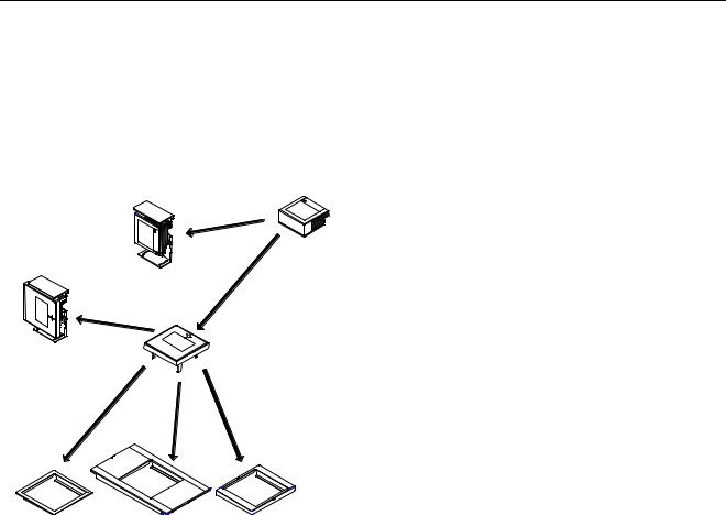
NCR RealScan 7883 Mountings
The NCR RealScan 7883 Scanner is a small, compact laser scanner available in two models. The RealScan 7883-1000 has many of the same features found in larger scanners. The RealScan 7883-1200 has the same capabilities as the 7883-1000; however, it uses the new Super ASIC technology. The RealScan 7883 can be mounted horizontally in a checkstand or vertically above the checkstand. Various mounts are available for the RealScan 7883.
Scanner
|
Vertical Mount |
|
Vertical Mount |
Top Plate |
|
(Horizontal Mount) |
||
With Top Plate |
||
|
Horizontal Mount |
Horizontal Mount |
Horizontal Mount |
Flat Plate Adapter |
7820 Adapter |
7852 Adapter |
18681
6 of 75 |
04/04 |
497-0424789 Release F |

NCR RealScan 7883 Installation and Owner Guide
Installation Instructions
When installing a RealScan 7883, it is recommended that you first mount the Power Supply and run all the cables. After connecting the unit to the host terminal, make any necessary programming changes and scan some good tags to verify that the scanner is communicating with the host terminal. After verifying that everything is working correctly, mount the unit in the checkstand. If the RealScan 7883 does not work properly, refer to the problem correcting section in this document:
Correcting Scanner Problems.
The following flowchart shows the sequence of installation steps. Detailed descriptions of each step follow.
Step 1 |
|
Installing Power Supply and |
|
|
|
|
|||
|
Interface Cables |
|
||
|
|
|
||
|
|
|
|
|
|
|
|
|
|
Step 2 |
|
Setting Program Parameters and |
|
|
|
Verifying Host Connection |
|
||
|
|
|
||
|
|
|
|
|
Step 3 |
|
|
|
|
|
Setting the Scan Zone |
|
||
|
|
|
|
|
Step 4 |
|
|
|
|
|
Mounting the RealScan 7883 |
|
||
|
|
|
|
|
19762
497-0424789 Release F |
04/04 |
7 of 75 |
NCR RealScan 7883 Installation and Owner Guide
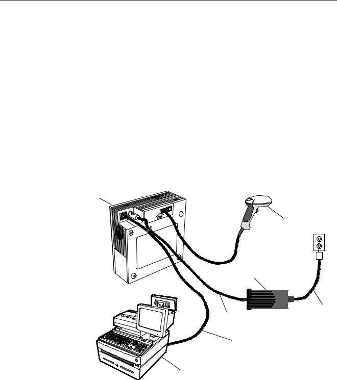
Step 1 - Installing Power Supply and Interface Cables
Connecting the Cables to an NCR RealScan 7883
The NCR RealScan 7883 is powered through an external Power Supply. An interface cable connects the RealScan 7883 to the host terminal. Two RS-232 peripheral ports are provided for connecting other devices such as an NCR 7837 HandHeld Scanner.
Note: If you are using a Keyboard Wedge cable, it must be plugged directly into the PS/2 port on the PC.
Standard Interface Connection
1.Install the Interface Cable between the RealScan 7883 and the host terminal.
2.Install the Power Supply. Locate it in the checkstand at least 10 inches (25.4 cm) from the RealScan 7883 installed position. Be sure to locate the Power Supply where spilled liquids cannot fall onto it.
3.Fasten a Tie-Wrap around the Power Cable and the Interface Cable to help secure the Power Cable.
RealScan 7883
CD
RealScan 7837
Power Supply
Power Cable
Power Cable
Interface Cable
Host Terminal
19767
8 of 75 |
04/04 |
497-0424789 Release F |
NCR RealScan 7883 Installation and Owner Guide
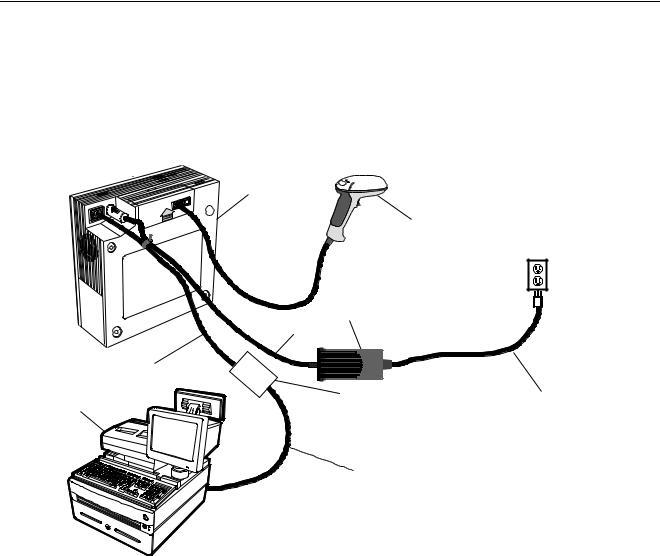
7883-1000 USB Interface Connection
Connecting a RealScan 7883-1000 Scanner to a USB port on a host terminal requires a special cable. One end of the Dongle Adapter Cable connects to the host terminal. The other end has an Interface Box that contains a printed circuit board with all the necessary circuitry. The host terminal supplies power for this circuitry. An Interface cable connects the scanner to this box. A Power Supply connected to the scanner is required for all configurations.
Interface Cable
Host Terminal
RealScan 7883
CD
RealScan 7837
Power Supply |
Power Cable |
Interface Box |
Power Cord |
|
Dongle Adapter Cable
19406
497-0424789 Release F |
04/04 |
9 of 75 |
NCR RealScan 7883 Installation and Owner Guide
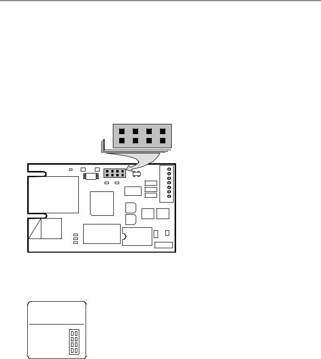
J3 in the Interface Box on the end of the Dongle Adapter Cable contains a shunt that must be correctly installed for the host terminal. The cable is shipped from the factory with a shunt on pins 3 and 4. The following four positions are available.
•Pins 1 & 2 – Wedge
•Pins 3 & 4 – IBM
•Pins 5 & 6 – RS-232
•Pins 7 & 8 – HID
The cover on the Interface Box latches together along one side. Carefully pry open the latched edge to open the Interface Box. Check the shunt position on J3 and change as needed. Close the Interface Box cover.
|
|
|
|
|
J3 |
|
|
|
|
W |
I |
R |
H |
|
|
1 |
|
|
|
7 |
|
|
2 |
|
|
|
8 |
C1 |
R4 |
R5 |
J3 |
|
|
|
|
|
U1 |
|
|
U4 |
|
|
|
|
|
|
|
|
|
|
R6 |
R7 |
|
C6 |
J5 |
|
|
U6 |
C5 |
|
||
|
|
|
|
|
||
J2 |
|
|
|
C4 |
|
|
|
|
|
|
|
||
|
|
U2 |
|
C3 |
|
|
|
|
|
|
U5 |
U7 |
|
|
|
|
|
C2 |
||
|
|
|
|
|
|
|
J1 |
|
|
|
|
C7 |
C8 |
R3 |
|
Y1 |
|
U3 |
|
|
R2 |
|
|
|
J4 |
||
|
|
|
|
|
||
R1 |
|
|
|
|
|
|
|
|
|
|
|
|
19573 |
The following label is attached to the outside of the Interface Box. It identifies the various interface settings.
J3 is set at the factory for IBM; move the shunt for other interfaces.
Shunt
Position Interface
1 to 2 |
Wedge |
3J |
3 to 4 |
IBM |
|
5 to 6 |
RS 232 |
|
7 to 8 |
HID |
|
H R I W 7 1 8 2
20001
7883-1200 USB Interface Connection
Connecting a RealScan 7883-1200 Scanner to a USB port on a host terminal requires a USB cable. No additional hardware is required. There are two cables available.
10 of 75 |
04/04 |
497-0424789 Release F |
NCR RealScan 7883 Installation and Owner Guide
For connecting to IBM and NCR terminals a latching or USB Plus Power cable should be used.
1416-C895-0050 - Cable - USB IBM, Latching
For connecting to PC’s, non-NCR/IBM terminals and NCR terminals without the USB Plus Power connector use cable below.
1416-C896-0050 - Cable-USB. Detachable
Auxiliary RS-232 Port
The NCR RealScan 7883 includes two Auxiliary RS-232 Peripheral Ports. The purpose of this feature is to permit other peripheral devices to connect to the host terminal through the RealScan 7883. This eliminates the need of the host terminal having additional RS-232 ports.
A typical use of this feature is to connect a hand-held scanner for scanning items too large to place on the checkstand. It also can provide a connection for some security tag deactivation systems.
Special programming is required for each peripheral device using a peripheral port. The connector is wired as follows.
|
Auxiliary RS-232 Port |
Pin Number |
Signal Name |
1 |
+5 Vdc |
2 |
NC |
3 |
GND |
4 |
TXD |
5 |
RXD |
6 |
+ 12 Vdc |
7 |
CTS |
8 |
RTS |
9 |
Frame |
10 |
Frame |
NCR RealScan 7835/7836
•1416-C313-0040 – Interface Cable
•1416-C397-0010 – Extension Cable
When a RealScan 7836 is attached to a RealScan 7883, the 7836 requires the following programming.
•Reset to serial (default values) – Label ZA
•Enable code ID (default values) – Label FB
NCR RealScan 7837
•1416-C445-0025 – Interface Cable
•1416-C397-0010 – Extension Cable
NCR RealScan 7832
•7832-K102-V001 - 7832 to RS-232 DB9 Female Serial Cable (POS H/W handshake)
•7832-K101-V001 - 7832 DB9 Male to RJ45 Cable adapter (78XX scanners)
NCR RealScan 7892
•1416-C695-0005 – RS-232 Daisy Chain Cable
•1416-C546-0030 – NCR 7892 Interface Cable
497-0424789 Release F |
04/04 |
11 of 75 |

NCR RealScan 7883 Installation and Owner Guide
Special Installations
RS-232 Peripherals
The RealScan 7883 includes two auxiliary RS-232 ports. This permits other peripheral devices to connect to the host terminal through the RealScan 7883, eliminating the need of the host terminal having additional RS-232 ports. Programming of the ports is required. The various sequences and the action taken is given below for handheld scanners. All options should be programmed because the scanner could have been previously programmed for a different option.
Programming the RealScan 7883
Program Mode
4 0 1 |
Enables Hand Held port |
** Port Selection **
4 |
0 |
2 |
Enables right hand port (Sensormatic) |
4 |
0 |
3 |
Enables left hand port (Scale, closest to arrow/PS connection) |
** 7883 Good Tone with auxiliary input **
4 0 4 |
Disables 7883 Tone with each scanned input |
4 0 5 |
Enables 7883 Tone with each scanned input |
** Scanner selection ** |
|
4 0 6 |
7835/7836/7837, programming information provided |
4 0 7 |
Symbol LS4000, must be programmed properly |
5 5 1 |
Enables port for 7832 format, programming information provided |
Save & Reset |
|
A typical use of this feature is to connect a hand-held scanner for scanning items too large to place on the checkstand. The 7892 may be programmed for compatibility with either the 7837 or 7832.
Additional Information
NCR RealScan 7892 Bi-Modal Presentation Scanner User Guide, 5005-0000-1182
NCR RealScan 7832 Operator’s Guide, 497-0434255
NCR RealScan 7837 Imaging Scanner User’s Guide, 497-0427357
RealScan 7892 Bi-Modal Presentation Scanner
You can connect a RealScan 7892 Bi-Modal Presentation Scanner to either Auxiliary RS-232 Port on
12 of 75 |
04/04 |
497-0424789 Release F |

NCR RealScan 7883 Installation and Owner Guide
the RealScan 7883.
Programming the RealScan 7892
Set the RealScan 7892 communication parameters to match the requirements of the RealScan 7883 auxiliary port. 7892 Programming requirements are provided below:
From standard RS-232 protocol
2 0 |
5 4 |
1 5 |
9600 baud, parity none, 1 stop, 8 data, RTS high wait CTS |
1 6 |
D |
|
Program label identifiers |
4 0 |
6 1 |
|
C39 – ‘a’ |
5 0 |
6 6 |
|
C128 – ‘f’ |
6 0 |
6 2 |
|
Interleaved 2 of 5 – ‘b’ |
End |
|
|
Label Identifier programming completed |
2 3 |
1 0 |
D |
CR (0DH) terminating byte |
(2 3 C 1 0 A |
LF (0AH) terminating byte (CR LF) Include for 7837 format; skip for 7832 format) |
||
Save & Reset |
|
||
You may also consult the Product Information / Features and Options / Auxiliary RS-232 Port. For a chart showing the auxiliary port requirements refer to the NCR 7892 Bi-Modal Presentation Scanner User Guide for information about programming the RealScan 7892.
RealScan 7832 Programming
Scan the tags listed below from the 7832 Operator’s Guide in order to program the 7832 for communicating with a 7883. NCR Factory Default
Disable ACK
Select Handshake Input
RealScan 7837 Programming
Program the RealScan 7837 according to the following chart. Refer to the RealScan 7837 User's Guide for more specific information.
Scan barcodes in order. If a triple beep is emitted from the scanner (7837), start over with the top barcode.
497-0424789 Release F |
04/04 |
13 of 75 |

NCR RealScan 7883 Installation and Owner Guide
FACTORY DEFAULT
1.
RS232, 7 DATA, 1 STOP, SPACE PARITY
2.
Prefixes / Code 39 - a, Code 128 - f, Code I 2of 5 - b
3.


Default Data Format
1.
UPC-A Prefix A
2.
UPC-E Prefix E
3.
EAN 13 Prefix F
4.
EAN 8 Prefix FF
5.
14 of 75 |
04/04 |
497-0424789 Release F |

NCR RealScan 7883 Installation and Owner Guide
Step 2 - Setting Program Parameters and Verifying Host
Connection
Now you need to turn on the NCR RealScan 7883. First load new firmware if needed then make any necessary program changes. Next scan a few tags to verify that the RealScan 7883 is communicating with the host terminal.
Note: The NCR 7883-1000 firmware cannot be flash. Only the NCR 7883-1200 firmware can be flash.
Turning on the RealScan 7883
The RealScan 7883 does not have an On/Off switch. Use the circuit breaker switch in the checkstand that supplies power to the unit as the On/Off switch. Put this switch in the On position.
Flash Latest Firmware – 7883-1200
Note: Firmware Flashing – Firmware flashing is only available on NCR RealScan scanners that have a Super ASIC Digital Board. The Super ASIC Digital Board models all have a 2 in the second digit of the model number. For example: 7872-x2xx, 7875-x2xx, 7876-x2xx, 7883-x2xx. Older NCR Scanners have firmware chips that cannot be updated by flashing. These chips must be replaced to change the firmware.
Although the latest firmware is loaded when the RealScan 7883-1200 is manufactured, newer firmware can be released after the unit is manufactured but before it is installed. NCR recommends that you check the number of the firmware in the RealScan 7883-1200 and compare it with the latest firmware available on www.NCR.com.
To identify the firmware already in the scanner, scan the Diagnostic Mode, Hex 4, & Hex A programming tags. These must be the first tags scanned after applying power to the unit. The RealScan 7883 gives a voice message containing the 497-xxxxxxx number of its firmware. Compare this number with the number of the firmware file on www.NCR.com.
Perform the firmware flashing procedure if the 497-xxxxxxx number of the firmware file on www.NCR.com is higher than what is already loaded in the RealScan 7883. Refer to the NCR RealScan 7883 User Guide for firmware flashing procedures.
Programming the RealScan 7883
Caution: Some host terminals can corrupt the RealScan 7883 program if they are running and are connected to the RealScan 7883 while you are making program changes. Either turn off the host terminal or disconnect the interface cable before scanning any programming tags.
497-0424789 Release F |
04/04 |
15 of 75 |

NCR RealScan 7883 Installation and Owner Guide
Programming Defaults
Scanning the Default programming tag sets most program parameters to the default programmed at the factory. The original defined default values are shown in the chart below. However, some parameters do not have default values so they are not changed, they stay as they are programmed.
01 Communications Protocol |
|
|
Protocol |
|
No default value – remains as programmed |
|
|
|
11 Good Read Tone |
|
|
Tone On/Off |
|
On |
Tone Frequency |
|
Choice 6 of 8 Levels |
Tone Length |
|
Choice 3 of 16 Levels |
Tone Volume |
|
Choice 4 of 8 Levels |
Not-On-File Volume |
|
Choice 2 of 8 Levels |
|
|
|
12 Timers |
|
|
Lockout Time |
|
900 Milliseconds |
Restart Lockout Timer |
|
Off |
Active Time |
|
15 Minutes |
|
|
|
13 Bar Codes – 1 |
|
|
UPC/EAN |
|
Enable |
Extend UPC-A To EAN-13 |
|
Disable |
Extend UPC-E To UPC-A |
|
Disable |
Periodical Codes |
Disable |
|
Periodical Code Extension |
|
2-Digit & 5-Digit |
Send Data |
Data As Decoded |
|
|
|
|
14 Bar Codes – 2 |
|
|
Code 39 |
|
Disable |
Minimum Characters Allowed |
8 |
|
Full ASCII |
Disable |
|
Check Digit Present |
|
Disable |
Transmit Check Digit |
|
Disable |
Allow 1- or 2-Character Tags |
|
Disable |
|
|
|
15 Bar Codes – 3 |
|
|
Interleaved 2 of 5 |
Disable |
|
Bar Code Length |
|
Range Check |
Value 1 |
08 |
|
Value 2 |
16 |
|
Check Digit Present |
|
Disable |
Transmit Check Digit |
|
Disable |
|
|
|
17 Bar Codes – 4 |
|
|
Code 128 |
Disable |
|
Minimum Data Characters |
3 |
|
UCC 128 |
|
Disable |
|
|
|
16 of 75 |
04/04 |
497-0424789 Release F |

NCR RealScan 7883 Installation and Owner Guide
18 Bar Codes – 5 |
|
|
|
|
|
|
|
RSS Enable |
|
|
Disable |
|
|
|
|
Scans Required On RSS 14 |
|
1 |
|
|
|
|
|
Scans Required On RSS E |
|
1 |
|
|
|
|
|
UCC1128 Emulation Mode |
|
Normal Mode |
|
|
|
||
16 Label Identifiers |
|
|
|
|
|
|
|
Identifier Type |
|
|
Default Prefix |
|
|
|
|
Common Byte 1 |
|
|
5D |
|
|
|
|
Common Byte 2 |
|
|
42 |
|
|
|
|
Bar Code Type |
|
|
No Default value – remains as programmed |
||||
|
UPC-A UPC-E |
EAN-8 |
EAN-13 |
Code 39 |
Code 128 I 2 of 5 |
||
Common Byte |
0 |
0 |
0 |
0 |
2 |
2 |
2 |
Unique Identifier |
41 Hex |
45 Hex |
46 Hex |
46 Hex |
31 Hex |
33 Hex |
32 Hex |
20 RS-232 Parameters – 1 |
|
|
|
|
|
|
|
Baud Rate |
|
|
9600 |
|
|
|
|
Parity |
|
|
Odd |
|
|
|
|
Stop Bits & Character Length |
|
1 Stop Bit, 7-Bit Character |
|
|
|||
Handshake |
|
|
RTS High Wait For CTS |
|
|
||
|
|
|
|
|
|
|
|
21 RS-232 Parameters – 2 |
|
|
|
|
|
|
|
BCC Options |
|
|
Enable if Scale installed |
|
|
||
Interface Control |
|
|
None |
|
|
|
|
Check Digit |
|
|
Enable UPC-A, Enable EAN-8, |
|
|||
|
|
|
Enable EAN-13, Disable UPC-E |
|
|||
|
|
|
|
|
|
|
|
22 RS-232 Prefix Byte |
|
|
|
|
|
|
|
Prefix Byte |
|
|
Disable |
|
|
|
|
ASCII Code |
|
|
02 |
|
|
|
|
|
|
|
|
|
|
|
|
23 RS-232 Terminator Byte |
|
|
|
|
|
|
|
Terminator Byte |
|
|
Enable |
|
|
|
|
ASCII Code |
|
|
03 |
|
|
|
|
|
|
|
|
|
|
|
|
24 RS-232 Communications Options |
|
|
|
|
|
|
|
Message Delay |
|
|
10 Milliseconds |
|
|
|
|
Scanner or Scanner/Scale Format |
Enable if Scale installed |
|
|
||||
Normal Or Eavesdrop Mode |
|
Normal Mode |
|
|
|
||
|
|
|
|
|
|
|
|
32 Miscellaneous Parameters |
|
|
|
|
|
|
|
IBM Tone Control |
|
|
Enable |
|
|
|
|
IBM Rexmit Control |
|
|
3 Times |
|
|
|
|
Enable / Disable Voice Messages |
None |
|
|
|
|
||
IBM Tag Data Format |
|
Hex |
|
|
|
|
|
|
|
|
|
|
|
|
|
497-0424789 Release F |
04/04 |
17 of 75 |

NCR RealScan 7883 Installation and Owner Guide
Programming for USB Connection
The RealScan 7883 Scanner must be properly programmed for USB. Programming and cabling depends on whether the unit is a 7883-1000 or 7883-1200. The 7883-1000 uses the USB Dongle connection to the host terminal while the 78831200 uses a straight through cable. The programming also depends on the type of host terminal being used.
RS-232 Communications
The 7883-1000 communicates with the USB dongle using RS-232. Therefore, the 7883-1000 uses standard RS-232 communications (1 0 5). The RealScan 7883-1200 Scanner outputs USB and uses a cable which connects directly to the terminal. It must be programmed for NCR/232USB. Other parameters may be set as required by the host terminal. Set the required program parameters by scanning the following sequence of programming tags. These must be the first tags scanned after supplying power to the unit.
7883-1000
1.Default – sets all parameters to standard default values.
2.Programming Mode – puts scanner in base programming state.
3.Hex 1, Hex 0, Hex 5 – sets the required RS-232 programming parameters.
•RS-232 communications protocol
•9600 baud
•Odd parity
•1 stop bit, 7-bit character
4.Change any other parameters as required by the host terminal.
5.Save and Reset – saves the program just entered and resets the scanner.
7883-1200
1.Default – sets all parameters to standard default values.
2.Programming Mode – puts scanner in base programming state.
3.Hex 1, Hex 0, Hex E, Hex 0 – sets the required NCR/232 USB programming parameters.
4.Change any other parameters as required by the host terminal.
5.Save and Reset – saves the program just entered and resets the scanner.
The host terminal software may now be configured to use the communication port assigned by the IO Networks driver in the terminal when the connection is made to USB. Note that it is required to obtain the IO Networks software which is available from the NCR website.
IBM Communications
The host terminal should assign the port and associate the scanner with the application when the USB connection is made. When programming a RealScan 7883 for IBM USB communications, all parameters are set to the standard default values, and the communications protocol is set to IBM USB. This is accomplished by scanning the following sequence of programming tags. These must be the first tags scanned after supplying power to the unit. Note that both the 7883-1000 and 7883-1200 use the same programming sequences. However, the 7883-1000 must use a USB dongle, while the 78831200 uses a USB cable. The jumper in the USB Dongle for 7883-1000 scanners must also be jumpered for IBM (See figure above).
7883-1000 and 7883-1200
1.Default - sets all parameters to standard default values.
2.Programming Mode tag - puts scanner in base programming state.
18 of 75 |
04/04 |
497-0424789 Release F |
NCR RealScan 7883 Installation and Owner Guide
3.Hex 1, Hex 0, Hex D - sets the communication protocol to IBM USB.
4.Hex 4, Hex 8, Hex 5 – turns off configuration message processing.
5.Change any other parameters as required by the host terminal.
6.Save and Reset – saves the parameters just entered and resets the RealScan 7883 Scanner
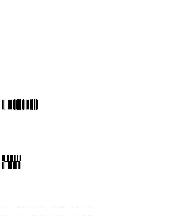
Reduced Space Symbology
Reduced Space Symbology (RSS) permits more data to be recorded in a smaller physical space. This is accomplished by encoding the data in large symbol characters rather than encoding each data character separately. Also, no quiet zone is required around the symbols. The RealScan 7883 can read four types of RSS bar codes.
RSS14
RSS-14 is a linear symbology that encodes 14 UCC/EAN digits. This structure provides four segments that can be scanned and decoded separately, then reconstructed. The total symbol contains 96 modules combined into 46 elements (bars and spaces).
0100012345678905
19254
RSS-14 Stacked
RSS-14 Stacked is a 2-row format. The bottom row is higher than the top row and the two are separated with a separator pattern. The stacked format is used when not enough linear space is available. A typical use is marking produce in a grocery store.
0100991234567899
19255
RSS Expanded
RSS Expanded is a variable length linear symbology. It can encode 74 numeric or 41 alpha characters. RSS Expanded can be scanned and decoded in up to 22 segments and then reconstructed.
|
|
|
|
|
|
|
|
|
|
|
|
|
|
|
|
|
|
|
|
|
|
|
|
|
|
|
|
|
|
|
|
|
|
|
|
|
|
|
|
|
|
|
|
|
|
|
|
|
9987 6543 2101 2345 6789 8888 |
19256 |
|||||||||||||||||||||||||||||||||||||||||||||||
RSS Expanded Stacked
RSS Expanded Stacked is similar to RSS-14 Stacked except it uses the RSS Expanded format for creating the symbol.
497-0424789 Release F |
04/04 |
19 of 75 |

NCR RealScan 7883 Installation and Owner Guide
0192 1234 5698 7457 3202 0000 9939 0200 296
19257
Enabling RSS
1.Turn on the circuit breaker to the RealScan 7883.
2.Enable the Reduced Space Symbology feature by scanning the following sequence of programming tags. These must be the first tags scanned after applying power to the unit.
•Programming Mode - Puts the RealScan 7883 in the Programming Mode.
•Hex 1, Hex 8, Hex A, Hex 3.
•Save and Reset - Saves the parameter setting.
Disabling RSS
1.Turn on the circuit breaker to the RealScan 7883.
2.Enable the Reduced Space Symbology feature by scanning the following sequence of programming tags. These must be the first tags scanned after applying power to the unit.
•Programming Mode - Puts the RealScan 7883 in the Programming Mode.
•Hex 1, Hex 8, Hex A, Hex 0.
•Save and Reset - Saves the parameter setting.
Making Other Program Changes
If you still need to make program changes after setting the communication parameters, you can enter information directly from the Programming Worksheets. The Programming Worksheets, located at the back of this book, identify all the available program parameters. Each worksheet relates to a specific programming mode. Most programming options have defaults, identified by a heavy box, that are determined at the factory. Scanning the Default tag as the first tag after applying power to the RealScan 7883 sets the parameters to these values.
Changing the RealScan 7883 program is accomplished by scanning the proper sequence of programming tags, which are included with the unit. Following are three major steps for making program changes.
1.Enter the Base Programming State by scanning the Programming Mode tag as the first tag after applying power to the RealScan 7883.
2.Select a Programming Worksheet and enter its parameter data by scanning the appropriate Hex tags.
3.Save the program by scanning the Save and Reset tag.
Note: In most instances the factory determined defaults are the correct parameter setting. However, if you do need to make changes, it is recommended that you first set all parameters to default values, then make any necessary changes to the appropriate parameters.
20 of 75 |
04/04 |
497-0424789 Release F |
NCR RealScan 7883 Installation and Owner Guide
Scan Sample Tags
Now you should scan some sample tags to verify that the RealScan 7883 is communicating with the host terminal. Following are four good tags that you can use. After verifying that the RealScan 7883 is communicating properly with the host terminal, continue with the installation.
Note: For maximum performance, full size labels must be used. The UPC Symbol Specification Manual gives the exact size requirements for UPC labels. If the bar height is less than specified, more precise presentation to the scanner is required, reducing productivity.
UPC-A
|
|
|
|
|
|
|
|
|
|
|
|
|
|
|
|
|
|
|
|
|
|
|
|
|
|
|
|
|
|
|
|
|
|
|
|
|
|
|
|
|
|
|
|
|
|
|
|
|
|
|
|
|
|
|
|
|
|
|
|
|
|
|
|
|
|
|
|
|
|
|
|
|
|
|
|
|
|
|
|
|
|
|
|
|
|
|
|
|
|
|
|
|
|
|
|
|
|
1 |
|
|
|
|
|
|
|
|
|
|
|
|
|
|
|
7 7 0 6 2 |
|
|
|
|
|
|
|
3 7 9 2 0 |
|
|
|
|
|
|
|
|
|
|
|
|
4 |
|||||||||||
|
|
|
|
|
|
|
|
|
|
|
|
|
|
|
|
|
|
|||||||||||||||||||||||||||||||
Code 39
1 |
7 |
7 |
0 |
6 |
2 |
3 |
7 |
9 |
2 |
0 |
Code 128
1 7 7 0 6 2 3 7 9 2 0
Interleaved 2 of 5
0 1 7 7 0 6 2 3 7 9 2 0
497-0424789 Release F |
04/04 |
21 of 75 |
NCR RealScan 7883 Installation and Owner Guide
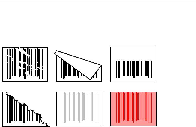
Determining Label Quality
Many labels in a typical retail environment are unreadable. The following illustration shows some of the common problems. Vendors and printers regularly supply products to the market with bar codes that are overprinted, underprinted, or truncated. Some labels have missing margins. Others may be printed around the corners of packages, or on media not likely to remain flat when picked up.
0 |
01234 5 6789 |
6 |
Bar Code Scratched
0 |
01234 5 6789 |
6 |
|
Bar Code Torn |
|
0 |
01234 5 67 89 |
6 |
Bar Code Folded
0 |
01234 5 6789 |
6 |
Poor Color Contrast
0 |
0 1 2 34 567 8 9 |
6 |
|
|
|
Bar Code Truncated
0 |
01234 5 678 9 |
6 |
Red Bar Code On
Red Background
R0026
The readability of a label depends on variables such as size, placement, color, paper type, ink viscosity, and package coatings. The middle of a printing run can yield erroneous labels due to the many variants involved. In particular, poor color contrast and marginal print quality can make a label hard to read.
UPC bar code requirements are identified in the UPC Symbol Specification Manual that is published by the Uniform Code Council, Inc. Contact the following for a copy of this document.
Uniform Code Council, Inc.
8163 Old Yankee Road, Suit J Dayton, OH 45458
Phone: 513-435-3870
Contact the following for information on Code 39 or "3 of 9" bar code labels.
AIM – USA
634 Alpha Dr.
Pittsburgh, PA 15238-2802
Phone: 412-963-8588
EAN bar code requirements are identified in General Specification for Article Symbol Marking, Copyright EAN-1977.
22 of 75 |
04/04 |
497-0424789 Release F |
NCR RealScan 7883 Installation and Owner Guide
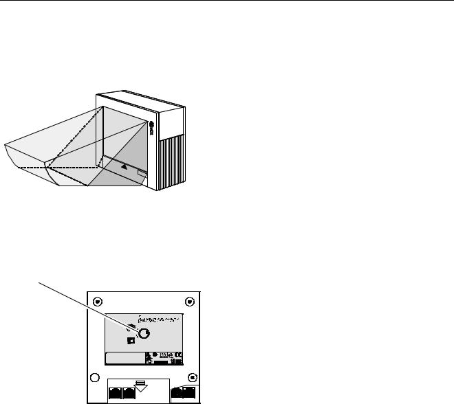
Step 3 - Setting RealScan 7883 Scan Zone
The scan zone on a NCR RealScan 7883 Scanner can be set to horizontal or vertical. Changing the scan zone changes the angle of the scan lines coming from the scanner.
Vertical |
Horizontal |
Scanning |
Scanning |
16011
You change the scan zone by turning the screw on the bottom of the cabinet. Be sure to turn the screw all the way in one direction or the other, do not leave it turned part way.
Scan Zone
Adjusting Screw
Complies with FDA radiation Performance standards 21 CFR Subchapter J.
NCR Corporation
Duluth, Ga. 30096
VCCI-1
This device complies with Part 15 of the FCC Rules. Operation is subject to the following two conditions: (1) This device may not cause harmful interference, and (2) this device must accept any interference received
including interference that may cause undesired operation.
 This apparatus does not exceed the Class A limits for Horizontal radio noise emissions set out in the Radio Interference
Regulations of Canada.
Vertical |
Le présent appareil ñ émet pas de bruits radioeléctriques |
|
depassant les limites de la Classe A prescrites dans le |
|
Reglement sur le brouillage radioeléctrique du Canada. |
|
One or more of the U.S. Patents listed below apply: |
4,868,375 4,797,551 4,851,667 4,235,018
4,272,675 4,282,426, 4,679,154 5,194,722
5,276,316 5,334,825 5,262,625 5,256,865
5,144,114 5,065,842 5,023,818 5,459,310
5,588,621 5,661,297 5,773,767 5,975,417
Class: 7883 |
Serial: |
I.T.E. |
Model: |
Made In: |
|
|
|
LISTED |
Date Manufactured: |
E152553 |
|
5/12/ -12VDC; 1.2/0.4/0.2A |
15W (max) |
|
20152
When selecting the scan zone, you must also consider how you are mounting the scanner, horizontally or vertically. This permits you to optimize the performance for your particular installation. Following are four common installations that identify the installation type and the scan zone setting. They are given in order of scanning efficiency with the first being the most efficient, and the last being the least.
497-0424789 Release F |
04/04 |
23 of 75 |
Loading...