


 Loading...
NCR EasyPoint 7401
Release 2.5
Hardware User's Guide
N CR
19797
B005-0000-1254
Issue H

The products described in this book are licensed products of NCR Corporation.
MicroTouch is a registered trademark of MicroTouch.
NCR and EasyPoint are registered trademarks of NCR Corporation. Novell and Netware are registered trademarks of Novell, Inc. Pentium is a registered trademark of Intel Corporation.
Power Mon II is a registered trademark of Systems Enhancement Corporation. Sound Blaster is a registered trademark of Creative Technology, Ltd. SoundFusion is a registered trademark of Cirrus Logic, Inc.
Microsoft, Windows, and Windows NT are registered trademarks of Microsoft Corporation.
Symantic and Ghost are registered trademarks of Symantec Corporation in the United States and other countries.
It is the policy of NCR Corporation (NCR) to improve products as new technology, components, software, and firmware become available. NCR, therefore, reserves the right to change specifications without prior notice.
All features, functions, and operations described herein may not be marketed by NCR in all parts of the world. In some instances, photographs are of equipment prototypes. Therefore, before using this document, consult with your NCR representative or NCR office for information that is applicable and current.
To maintain the quality of our publications, we need your comments on the accuracy, clarity, organization, and value of this book.
Address correspondence to:
Manager, Information Products
NCR Corporation
2651 Satellite Blvd.
Duluth, GA 30096
Copyright © 2002
By NCR Corporation
Dayton, Ohio U.S.A.
All Rights Reserved

i
Preface
Audience
This book is written for hardware installer/service personnel, system integrators, and field engineers.
Notice: This document is NCR proprietary information and is not to be disclosed or reproduced without consent.
Safety Warnings
Servicing
Caution: This product does not contain user serviceable parts. Servicing should only be performed by a qualified service technician.
Fuse Replacement
Caution: For continued protection against risk of fire, replace only with the same type and ratings of fuse.
Attention: Pour prévenir et vous protéger contre un risque de feu, remplacer la fusible avec une autre fusible de même type, seulement.
Power Supply Cord Used as Disconnect Means
Caution: The power supply cord is used as the main disconnect device. Ensure that the socket outlet is located/installed near the equipment and is easily accessible.
Attention: Le cordon d'alimentation est utilisé comme interrupteur général. La prise de courant doit être située ou installée å proximité du matériel et être facile d'accés.
Lithium Battery Warning
Caution: Danger of explosion if battery is incorrectly replaced. Replace only with the same or equivalent type as recommended by the manufacturer. Discard used batteries according to the manufacturer's instructions.

ii
Attention: Il y a danger d'explosion s'il y a remplacement incorrect de la batterie. Remplacer uniquement avec une batterie du même type ou d'un type recommandé par le constructeur. Mettre au rébut les batteries usagées conformément aux instructions du fabricant.
Battery Disposal (Switzerland)
Refer to Annex 4.10 of SR814.013 for battery disposal.
IT Power System
This product is suitable for connection to an IT power system with a phase-to-phase voltage not exceeding 240 V.
Peripheral Usage
This terminal should only be used with peripheral devices that are certified by the appropriate safety agency for the country of installation (UL, CSA, TUV, VDE) or those which are recommended by NCR Corporation.
Caution: DO NOT connect or disconnect a printer, keyboard, or any other terminal-powered peripheral while the terminal is powered on. Doing so may result in peripheral or system damage.
System Weight Considerations
Warning: The NCR 7401-1xxx and 7401-2xxx terminals must be mounted securely to prevent a hazard. They must be installed in accordance with local building codes. The post or wall on which the unit is mounted should be able to withstand four times the weight of the unit, which is approximately 20 lbs. (9 kg). The NCR 7401-4xxx is a desk-top unit that has an assembled weight of approximately 90 lbs. (40.8 kg).
Environmental Consciousness
NCR is demonstrating its concern for the environment by designing an intelligent power management system into this terminal that operates efficiently whether the system is in a stand-alone or network environment.

iii
Grounding Instructions
In the event of a malfunction or breakdown, grounding provides a path of least resistance for electric current to reduce the risk of electric shock. This product is equipped with an electric cord having an equipment-grounding conductor and a grounding plug. The plug must be plugged into a matching outlet that is properly installed and grounded in accordance with all local codes and ordinances. Do not modify the plug provided – if it will not fit the outlet, have the proper outlet installed by a qualified electrician. Improper connection of the equipment-grounding conductor can result in a risk of electric shock. The conductor with insulation having an outer surface that is green with or without yellow stripes is the equipment-grounding conductor. If repair or replacement of the electric cord or plug is necessary, do not connect the equipment-grounding conductor to a live terminal. Check with a qualified electrician or service personnel if the grounding instructions are not completely understood, or if in doubt as to whether the product is properly grounded.
Use only 3-wire extension cords that have 3-prong grounding plugs and 3-pole receptacles that accept the product’s plug. Repair or replace damaged or worn cords immediately.
References
•NCR EasyPoint 7401 Hardware Service Guide (B005-0000-1341)
•NCR EasyPoint 7401 Site Preparation Guide (B005-0000-1255)
•NCR EasyPoint 7401 Interface Guide (B005-0000-01405)
•NCR EasyPoint 7401 ATX 38 Printer User’s Manual
(B005-0000-1454)
•NCR EasyPoint 7401/7454 Retail Terminal Parts Identification Manual
(B005-0000-1072)
•NCR FitClient Software User's Guide (B005-0000-1235)
•NCR EasyPoint 7401 Migration Guide (B005-0000-1500)
•NCR Retail Platform Software Terminal Utilities Guide
(B005-0000-1503)

iv
Table of Contents
Chapter 1: 7401-2xxx and 3xxx Product Overview |
|
Introduction .................................................................. |
1-1 |
Serial Number/Model Number Label........................ |
1-2 |
Fixed-Angle Mount Label...................................... |
1-2 |
Tilt-Mount Label .................................................... |
1-3 |
Hardware Modules ...................................................... |
1-4 |
Base Unit ................................................................. |
1-4 |
Hardware Options ................................................. |
1-5 |
Terminal Components not Supported.............. |
1-7 |
System Configuration Diagram................................... |
1-8 |
Kit Configuration Diagram.......................................... |
1-9 |
Hardware Module Descriptions................................ |
1-10 |
Processor Board.................................................... |
1-10 |
Processor/Chip Set .......................................... |
1-10 |
Video Subsystem.............................................. |
1-11 |
Ethernet 10/100Base-T LAN |
|
Communications.............................................. |
1-12 |
Wireless LAN Communications ..................... |
1-13 |
Universal Serial Bus......................................... |
1-14 |
Serial Ports........................................................ |
1-14 |
Hardware Monitor........................................... |
1-15 |
PCI Expansion Header .................................... |
1-15 |
IDE Header....................................................... |
1-15 |
Audio ................................................................ |
1-16 |
Magnetic Stripe Reader ................................... |
1-16 |
Touch Screen Controller .................................. |
1-16 |
Processor Board Connectors ........................... |
1-17 |
NCR Retail Specific Hardware........................ |
1-18 |

v
Board BIOS ....................................................... |
1-22 |
Operator Display.................................................. |
1-26 |
LCD Adapter Board......................................... |
1-26 |
LCD Backlight Inverter Module ..................... |
1-26 |
Touch Screen .................................................... |
1-27 |
Features ....................................................................... |
1-28 |
Magnetic Stripe Reader........................................ |
1-28 |
Printer Options..................................................... |
1-29 |
7401-K590 Self-Service Printer ........................ |
1-29 |
7401-K580 Self-Service Printer |
|
(Discontinued).................................................. |
1-30 |
7158 Printer....................................................... |
1-31 |
7167 Printer....................................................... |
1-31 |
7194 Printer....................................................... |
1-32 |
7197 Printer....................................................... |
1-32 |
Other Integrated Devices and Indicators ........... |
1-33 |
Hard Disk Drive............................................... |
1-33 |
Reset Switch...................................................... |
1-33 |
Internal Speaker ............................................... |
1-33 |
POS Connector Board ...................................... |
1-34 |
Motion Sensor .................................................. |
1-34 |
Power/Status LED........................................... |
1-35 |
Power OK LED................................................. |
1-35 |
LAN Status LEDs ............................................. |
1-35 |
Power Supply ................................................... |
1-36 |
Uninterruptible Power System (Optional)..... |
1-36 |
Integrated Scanner Module (Optional)........... |
1-36 |
Integrated Speaker Module (Optional) .......... |
1-37 |
Compact Flash (Optional) ............................... |
1-37 |
USB RS-232 Port Server ................................... |
1-37 |
Integrated CD-ROM Drive (Tilt Mount |
|
Model)............................................................... |
1-38 |

vi
Additional Connectors (Pentium III Board)....... |
1-39 |
Compatibility .............................................................. |
1-40 |
LAN Communications......................................... |
1-40 |
Application Programmability ............................. |
1-40 |
Operating System Information............................ |
1-40 |
Migration..................................................................... |
1-41 |
Retail Applications............................................... |
1-41 |
Retail Peripherals ................................................. |
1-41 |
Retail Systems....................................................... |
1-42 |
Platform ............................................................ |
1-42 |
Networks .......................................................... |
1-42 |
Platform Load................................................... |
1-42 |
Chapter 2: 7401-4xxx Product Overview |
|
Introduction .................................................................. |
2-1 |
Serial Number/Model Number Label........................ |
2-2 |
Hardware Modules ...................................................... |
2-3 |
Base Unit ................................................................. |
2-3 |
Hardware Options ................................................. |
2-4 |
Terminal Components not Supported.............. |
2-5 |
System Configuration Diagram................................... |
2-6 |
Hardware Module Descriptions.................................. |
2-7 |
Processor Board...................................................... |
2-7 |
Processor/Chip Set ............................................ |
2-7 |
Video Subsystem................................................ |
2-8 |
Ethernet 10/100Base-T LAN |
|
Communications................................................ |
2-8 |
Wireless LAN Communications ....................... |
2-9 |
Universal Serial Bus......................................... |
2-10 |
Serial Ports........................................................ |
2-11 |
Hardware Monitor........................................... |
2-12 |
PCI Expansion Header .................................... |
2-12 |

vii
IDE Header....................................................... |
2-12 |
Audio ................................................................ |
2-12 |
Magnetic Stripe Reader ................................... |
2-13 |
Touch Screen Controller .................................. |
2-13 |
Processor Board Connectors ........................... |
2-13 |
NCR Retail Specific Hardware........................ |
2-14 |
Board BIOS ....................................................... |
2-17 |
Operator Display.................................................. |
2-21 |
LCD Adapter Board......................................... |
2-21 |
LCD Backlight Inverter Module ..................... |
2-21 |
Touch Screen .................................................... |
2-22 |
Features ....................................................................... |
2-23 |
Secure Cabinet with Integrated Speakers........... |
2-23 |
Ruggedized Keyboard with Trackball................ |
2-23 |
Pin Pad .................................................................. |
2-24 |
Motorized Card Reader ....................................... |
2-24 |
Magnetic Stripe Reader........................................ |
2-25 |
Full Page Printer................................................... |
2-25 |
Other Integrated Devices and Indicators ........... |
2-26 |
Hard Disk Drive............................................... |
2-26 |
Integrated CD-ROM ........................................ |
2-26 |
Reset Switch...................................................... |
2-26 |
Compact Flash.................................................. |
2-27 |
Internal Speaker ............................................... |
2-27 |
POS Connector Board ...................................... |
2-27 |
USB Camera...................................................... |
2-27 |
Motion Sensor .................................................. |
2-28 |
Power/Status LED........................................... |
2-28 |
Power OK LED................................................. |
2-29 |
LAN Status LEDs ............................................. |
2-29 |
Power Supply ................................................... |
2-29 |

viii
Motorized Card Reader Power Supply .......... |
2-30 |
Full Page Printer Power Supply...................... |
2-30 |
Integrated Speakers ......................................... |
2-30 |
EasyPoint 45 Pedestal ...................................... |
2-31 |
Chapter 3: 7401-2xxx and 3xxx Hardware Installation |
|
Introduction .................................................................. |
3-1 |
Installation Summary............................................. |
3-1 |
Installation Restrictions................................................ |
3-2 |
Connecting the Cables.................................................. |
3-3 |
Fixed-Angle Mount (F504)..................................... |
3-3 |
Fixed-Angle Mount (F503)..................................... |
3-5 |
Cable Routing..................................................... |
3-7 |
Cable Connector Identification ......................... |
3-9 |
Tilt Mount............................................................. |
3-10 |
Cable Routing................................................... |
3-11 |
Cable Connector Identification ....................... |
3-12 |
Installing Peripherals ................................................. |
3-13 |
Installing a Transaction Printer........................... |
3-13 |
RS-232 Installation ........................................... |
3-13 |
USB Installation................................................ |
3-14 |
7401-K590 Self-Service Printer ........................ |
3-15 |
Installing a Cash Drawer ..................................... |
3-16 |
Installing a Second Cash Drawer.................... |
3-17 |
Installing PC Cards .............................................. |
3-18 |
Mounting a Fixed-Angle Mount Terminal............... |
3-21 |
7401-K522 Pedestal Mount .................................. |
3-22 |
7401-K521 Wall Mount ........................................ |
3-23 |
7401-K521 Wall Mount with 7401-K530 Pole |
|
Brackets................................................................. |
3-25 |
Installing a K501 Tilt Mount Terminal...................... |
3-32 |
7401-K533 Wall Mount ........................................ |
3-33 |
ix
Wall Mounting a 7401-K502 Core Module ............... |
3-34 |
7401-9212 LCD No-Cabinet (12.1-inch)..................... |
3-36 |
Installation Guidelines......................................... |
3-37 |
Mounting Specification Illustrations .................. |
3-38 |
7401-9512 LCD No-Cabinet (15-inch)........................ |
3-39 |
Installation Guidelines......................................... |
3-39 |
Mounting Specification Illustrations .................. |
3-40 |
4055 Uninterruptible Power System (UPS) .............. |
3-42 |
Installing the UPS................................................. |
3-42 |
Installing the Power Mon II Software.............. |
3-43 |
Configuring the Power Mon II Software......... |
3-43 |
Finalizing the Installation .......................................... |
3-44 |
Completing the OS Installation (Win2000) .... |
3-44 |
Completing the OS Installation (WinXPe) ..... |
3-44 |
Completing the OS Installation (WinNT)....... |
3-45 |
Completing the OS Installation (Win98) - |
|
(Discontinued).................................................. |
3-45 |
Setting Auto-Logon (WinNT Terminal).................... |
3-47 |
Installing a Serial Mouse............................................ |
3-52 |
Calibrating the Touch Screen .................................... |
3-53 |
Calibration Using MicroTouch (Windows)........ |
3-53 |
Calibration Using Microcal (DOS) ...................... |
3-55 |
Calibration From the BIOS .................................. |
3-56 |
Summary .......................................................... |
3-57 |
Out-of-Box Failures.............................................. |
3-57 |
Chapter 4: 7401-4xxx Hardware Installation |
|
Introduction .................................................................. |
4-1 |
Installation Summary............................................. |
4-1 |
U.K. Keyboard Configuration ............................... |
4-1 |
Windows 2000 .................................................... |
4-1 |

x
Windows XPe ..................................................... |
4-2 |
Windows NT ...................................................... |
4-3 |
Installation Restrictions................................................ |
4-4 |
Connecting the Cables.................................................. |
4-5 |
Cable Routing..................................................... |
4-5 |
Cable Connector Identification ......................... |
4-5 |
Installing Peripherals ................................................... |
4-6 |
Installing the Angled Magnetic Stripe Reader |
|
(MSR)....................................................................... |
4-6 |
Installing Country Keyboards............................... |
4-8 |
Using the Full Page Printer........................................ |
4-13 |
Loading the Paper ................................................ |
4-13 |
Removing Paper from the Printer Feed Rolls .... |
4-14 |
Removing Power from the Printer...................... |
4-14 |
Using the Printer Test and Display Panel .......... |
4-15 |
Display LED Indicators ................................... |
4-15 |
Panel Switches.................................................. |
4-16 |
Full Page Printer Diagnostics and Setup ............ |
4-17 |
Installing a 7401-4xxx on a Table Top Mount .......... |
4-18 |
Mounting Procedures .......................................... |
4-18 |
Accessing the Mounting Screws ..................... |
4-19 |
Installing a 7401-4xxx on the EasyPoint 45 Pedestal 4-21
4055 Uninterruptible Power System (UPS) .............. |
4-22 |
Installing the UPS................................................. |
4-22 |
Installing the Power Mon II Software.............. |
4-23 |
Configuring the Power Mon II Software......... |
4-23 |
Finalizing the Installation .......................................... |
4-24 |
Completing the OS Installation (Win2000) .... |
4-24 |
Completing the OS Installation (WinXPe) ..... |
4-24 |
Completing the OS Installation (WinNT)....... |
4-25 |
Completing the OS Installation (Win98) - |
|
(Discontinued).................................................. |
4-25 |

xi
Calibrating the Touch Screen .................................... |
4-27 |
Calibration Using MicroTouch (Windows)........ |
4-27 |
Calibration Using Microcal (DOS) ...................... |
4-29 |
Calibration from the BIOS ................................... |
4-30 |
Summary .......................................................... |
4-31 |
Out-of-Box Failures.............................................. |
4-31 |
Chapter 5: Setup |
|
Introduction .................................................................. |
5-1 |
Entering Setup without a Keyboard ..................... |
5-1 |
Entering Setup Using a Keyboard......................... |
5-2 |
How to Select Menu Options ................................ |
5-2 |
Setting the Date and Time ..................................... |
5-3 |
Setting Passwords .................................................. |
5-3 |
Configuring a Hard Drive ..................................... |
5-4 |
Setting Memory Cache........................................... |
5-4 |
Setting Memory Shadow ....................................... |
5-5 |
Setting Boot Options .............................................. |
5-5 |
Allocating Interrupts.............................................. |
5-5 |
Restoring Factory Settings..................................... |
5-6 |
BIOS Default CMOS Values (7401- |
|
22xx/35xx/45xx BIOS Version 2.2.1.x)................. |
5-7 |
Main Values........................................................ |
5-7 |
Advanced Values ............................................... |
5-8 |
Security Values................................................. |
5-13 |
Power Values.................................................... |
5-13 |
Boot Values....................................................... |
5-13 |
Exit Values........................................................ |
5-14 |
Interrupts (7401-22xx/35xx/45xx BIOS |
|
Version 2.2.1.x) ..................................................... |
5-14 |
Memory Map (7401-22xx/35xx/45xx BIOS |
|
Version 2.2.1.x) ..................................................... |
5-16 |

xii
BIOS Default CMOS Values (7401-26xx/46xx |
|
BIOS Version 2.3.x.x)............................................ |
5-17 |
Main Values...................................................... |
5-17 |
Advanced Values ............................................. |
5-18 |
Security Values................................................. |
5-23 |
Power Values.................................................... |
5-23 |
Boot Values....................................................... |
5-23 |
Exit Values........................................................ |
5-24 |
Interrupts (7401-26xx/46xx BIOS |
|
Version 2.3.x.x) ..................................................... |
5-24 |
Memory Map (7401-26xx/46xx BIOS |
|
Version 2.3.x.x) ..................................................... |
5-26 |
BIOS Default CMOS Values (7401-21xx/31xx |
|
BIOS Version 1.5.0.4 - Discontinued).................. |
5-27 |
Main Values...................................................... |
5-27 |
Advanced Values ............................................. |
5-29 |
I/O Device Configuration ............................... |
5-29 |
PCI Configuration............................................ |
5-29 |
Interrupts (7401-21xx/31xx BIOS |
|
Version 1.5.0.4 - Discontinued) ........................... |
5-30 |
Memory Map (7401-21xx/31xx BIOS |
|
Version 1.5.0.4 - Discontinued) ........................... |
5-31 |
Chapter 6: Operating System Recovery |
|
Introduction .................................................................. |
6-1 |
Prerequisites ........................................................... |
6-1 |
Updating Procedures ............................................. |
6-3 |
Completing the OS Installation (Win2000) ...... |
6-5 |
Completing the OS Installation (WinXPe) ....... |
6-5 |
Completing the OS Installation (WinNT)......... |
6-6 |
Completing the OS Installation (Win98) – |
|
(Discontinued).................................................... |
6-6 |
Gold Disk Contents ...................................................... |
6-8 |

xiii
Microsoft Operating System License |
|
Agreements............................................................. |
6-8 |
Operating System Restrictions .............................. |
6-9 |
Standby and Hibernate Mode Restriction........ |
6-9 |
NCR 7401-22xx/25xx/32xx/35xx Win2000 |
|
Operating System Recovery Software (Version |
6-9 |
02.03.00.01).............................................................. |
|
NCR 7401-26xx/46xx Win2000 Operating |
|
System Recovery Software |
6-11 |
(Version 02.05.00.02) ............................................. |
|
NCR 7401-45xx Win2000 Operating System |
|
Recovery Software (Version 02.04.00.02)............ |
6-14 |
NCR 7401-22xx/25xx/32xx/35xx WinXPe |
|
Operating System Recovery Software |
6-16 |
(Version 02.05.00.01) ............................................. |
|
NCR 7401-26xx/46xx WinXPe Operating |
|
System Recovery Software |
6-18 |
(Version 02.05.00.01) ............................................. |
|
NCR 7401-/22xx/25xx/26xx/32xx/35xx NT |
|
Operating System Recovery Software |
6-20 |
(Version 02.05.00.02) ............................................. |
|
NCR 7401-21xx/31xx NT Operating System |
|
Recovery Software (Version 01.04.01.00)............. |
6-22 |
NCR 7401-4xxx NT Operating System Recovery |
|
Software (Version 02.05.00.02)............................. |
6-24 |
NCR 7401-22xx/25xx/32xx/35xx Win98 |
|
Operating System Recovery Software |
6-26 |
(Version 02.03.00.01) ............................................. |
|
NCR 7401-21xx/31xx Win98 Operating System |
|
Recovery Software (Version 01.01.00.00)............. |
6-28 |
OS Recovery from a Larger Disk Image ................... |
6-29 |

xiv
Chapter 7: BIOS Updating Procedures |
|
Introduction .................................................................. |
7-1 |
Prerequisites ........................................................... |
7-1 |
Updating Procedures ............................................. |
7-2 |
BIOS Crisis Recovery ................................................... |
7-5 |
Recovery Procedures ............................................. |
7-6 |
Cable/Connector Pin-Out Information ...................... |
7-9 |
Chapter 8: NCR 7401/7890 or 7892 Scanner Differences |
|
Introduction .................................................................. |
8-1 |
Starting the 7401 Scanner Motor and Laser.......... |
8-2 |
Programming the 7401 Scanner Using |
|
Programming Tags................................................. |
8-3 |
Programming the 7401 Scanner Through the |
|
RS-232 Interface...................................................... |
8-4 |
7401 Scanner Default Settings ............................... |
8-5 |
Appendix A: Cables |
|
7401 Cables ............................................................ |
A-1 |
Appendix B: Feature Kits |
|
7401 Kits.................................................................. |
B-1 |
Index

xv
Revision Record
Issue |
Date |
Remarks |
|
|
|
A |
Aug 00 |
First issue (separated 7401 and 7454 sections out of |
|
|
B005-0000-1069) |
|
|
|
B |
Feb 01 |
Updated to Release 2.2 |
|
|
Removed hardware service information from this |
|
|
document which was previously called the 7401 |
|
|
Web Kiosk Hardware Installation and Service Guide |
|
|
(B005-0000-1254) and renamed it the 7401 Web Kiosk |
|
|
Hardware User's Guide (B005-0000-1254). The |
|
|
hardware service information was placed in a new |
|
|
document, the 7401 Web Kiosk Hardware Service |
|
|
Guide (B005-0000-1341). |
CJune 01 Updated to Release 2.3
DSept 01 Updated BIOS screens. Added PC Card
installation.
EDec 01 Additional updates for Release 2.3
FMay 02 Updated to Release 2.4.
Changed Web Kiosk to EasyPoint 7401.
Added EasyPoint 7401-45xx terminal
F |
Aug 02 |
Add EasyPoint 45 Pedestal |
|
|
|
G |
Sep 02 |
Add Country Keyboards to 7401-45xx |
|
|
|
H |
Dec 02 |
Updated to Release 2.5 |
|
|
Added 7401-26xx and 7401-46xx models |
|
|
Changed 7401-45xx references to 7401-4xxx |
|
|
|

xvi
xvii
Radio Frequency Interference Statements
Federal Communications Commission (FCC)
Information to User
This equipment has been tested and found to comply with the limits for a Class A digital device, pursuant to Part 15 of FCC Rules. These limits are designed to provide reasonable protection against harmful interference when the equipment is operated in a commercial environment. This equipment generates, uses, and can radiate radio frequency energy and, if not installed and used in accordance with the instruction manual, may cause harmful interference to radio communications. Operation of this equipment in a residential area is likely to cause interference in which case the user will be required to correct the interference at his own expense.
NCR is not responsible for any radio or television interference caused by unauthorized modification of this equipment or the substitution or attachment of connecting cables and equipment other than those specified by NCR. The correction of interference caused by such unauthorized modification, substitution or attachment will be the responsibility of the user. The user is cautioned that changes or modifications not expressly approved by NCR may void the user's authority to operate the equipment.
Canadian Department of Communications
This Class A digital apparatus complies with Canadian ICES-003.
This digital apparatus does not exceed the Class A limits for radio noise emissions from digital apparatus set out in the Radio Interference Regulations of the Canadian Department of Communications.
Cet appareil numérique de la classe A est conforme à la norme NMB-003 du Canada.
Le présent appareil numérique n'émet pas de bruits radioélectriques dépassant les limites applicables aux appareils numériques de la classe A prescrites dans le règlement sur le brouillage radioélectriques édicté par le ministrère des Communications du Canada.
Voluntary Control Council for Interference (VCCI)

xviii
International Radio Frequency Interference Statement
Warning: This is a Class A product. In a domestic environment this product may cause radio interference in which case the user may be required to take adequate measures.
xix
IEC & EN Laser Product Label
CAUTION: Laser |
|
|
|
This laser module |
|
|
|||
radiation when |
|
|
|
does not comply |
open and interlock |
|
|
|
with 21CFR1040. |
defeated. |
|
|
|
USE ONLY AS A |
DO NOT STARE |
|
|
|
Component. |
INTO BEAM. |
|
|
|
|
|
|
|
|
|
|
|
|
|
|
(Label is attached to laser module inside the cabinet.)
Class IIa Laser Product. |
Appareil à Laser de classe IIa |
Class IIa Producto Laser. Tratè |
Avoid Long-term Viewing |
Eviter Toute Exposition Prolongèe |
De no ver directamente èl Rayo |
of Direct Laser Light. |
de la vue à la lumiè re laser directe. |
Laser por mucho tiempò. |
IEC & EN 60825-1 CLASS 1 LASER PRODUCT
17325
Laser Power
The NCR 7401 Scanner is not intended for long-term viewing of direct laser light. However, the unit is safe if used as intended. This scanner meets the following laser/LED power requirements.
•Class IIa CDRH (Center for Devices and Radiological Health)
•Class IIa Laser—Avoid long-term viewing of direct laser light
•Class 1 EN60-825 (Europäische Norm)
Following is the radiant energy of the laser/LED light as applied to each of the specified requirements.
Accessible Emission Limit (CDRH Calculation) |
0.99 Milliwatts |
Accessible Emission Limit EN60 825-1:1994+AII:1996 |
0.81 Milliwatts |
Caution: Use of controls or adjustments or performance of procedures other than specified herein may result in hazardous radiation exposure.

xx
Declaration of Conformity
Manufacturer's Name |
NCR Corporation |
|
|
Manufacturer's Address |
NCR Corporation |
|
Retail Solutions Division – Atlanta |
|
2651 Satellite Boulevard |
|
Duluth, GA 30096-5810 |
|
|
Type of Equipment |
Information Technology Equipment |
|
|
Model Number |
Class 7401-2xxx and 7401-3xxx |
|
|
Electrical Ratings (Input) |
100-120 V/200-240 V, 2.0 A/1.0 A, 50-60 Hz |
|
|
NCR Corporation, 1700 South Patterson Boulevard, Dayton, OH 45459, USA, declares that the equipment specified above conforms to the referenced EU Directives and Harmonized Standards.
EU Directive |
Harmonized Standard(s) |
89/336/EEC (EMC) |
EN 55022 |
|
EN 55024 |
|
EN61003-2 |
|
EN61003-3 |
73/23/EEC (Low Voltage) EN 60 950: A1 + A2 + A3 + A4 + All
NCR Corporation
Retail Solutions Division — Atlanta
2651 Satellite Boulevard
Duluth, GA 30096-5810
European Contact:
International IP Counsel
206 Marylebone Road
London, NW1 6LY, England

xxi
Declaration of Conformity
Manufacturer’s Name |
NCR Corporation |
|
|
Manufacturer’s Address |
NCR Corporation |
|
Retail Solutions Division – Atlanta |
|
2651 Satellite Boulevard |
|
Duluth, GA 30096-5810 |
|
|
Type of Equipment |
Information Technology Equipment |
|
|
Model Number |
Class 7401-4xxx |
|
|
Electrical Ratings (Input) |
100 - 240 V, 5.0 A, 50-60 Hz |
|
|
NCR Corporation, 1700 South Patterson Boulevard, Dayton, OH 45459, USA, declares that the equipment specified above conforms to the referenced EU Directives and Harmonized Standards.
EU Directive |
Harmonized Standard(s) |
89/336/EEC (EMC) |
EN 55022 |
|
EN 55024 |
|
EN61003-2 |
|
EN61003-3 |
|
|
73/23/EEC (Low Voltage) |
EN 60 950: A1 + A2 + A3 + A4 + All |
|
|
NCR Corporation
Retail Solutions Division — Atlanta
2651 Satellite Boulevard
Duluth, GA 30096-5810
European Contact:
International IP Counsel
206 Marylebone Road
London, NW1 6LY, England

xxii
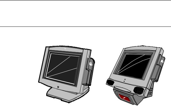
Chapter 1: 7401-2xxx and 3xxx Product Overview
NCR
Tilt Mount |
Fixed-Angle Mount |
18289 |
Introduction
The NCR EasyPoint 7401 is an interactive touch screen terminal with retail functionality that supports a variety of kiosk and self-service applications. The 7401 is housed in an integrated, compact cabinet and can be tilt mounted, fixed-angle mounted or flush mounted.
The major hardware features of the 7401 are a 12.1-inch or 15-inch flat panel display with touch screen input and LAN connectivity, plus optional magnetic stripe reader, infrared reader, scanner, stereo audio, self service printer and wireless LAN. It also supports custom kiosk environments.
The 7401 is Internet/Intranet ready. System loading occurs from a network server, and software and data content are delivered from a server through standard Internet protocols.

1-2 Chapter 1: 7401-2xxx and 3xxx Product Overview
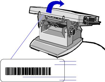
Serial Number/Model Number Label
The unit's serial number, model number, tracer number, and date of manufacture are included on a label on the back of the Core Module. Refer to following sections for additional information.
Note: The serial number is repeated on the non-MSR side of the Core Module.
Fixed-Angle Mount Label
To view the label:
•For non-hinged mounts, remove the Core Module from the mount.
•For hinged mounts, the Core Module does not have to be removed.
NCR |
7401-3000-8000 |
|
|
|
|
Class/Model |
||||||||||||||||||||||||||
|
|
|
|
Serial Number |
||||||||||||||||||||||||||||
|
|
|
|
50-12345678 |
|
|
|
|
|
|||||||||||||||||||||||
|
|
|
|
|
|
|
|
|
||||||||||||||||||||||||
|
|
|
|
|
|
|
|
|
|
|
|
|
|
|
|
|
|
|
|
|
|
|
|
|
|
Mfg |
|
|
|
|
Date Manufactured |
|
|
|
|
|
|
|
|
|
|
|
|
|
|
|
|
|
|
|
|
|
|
|
|
|
|
|
|
|
|
|
|||
Date: |
11/15/01 |
|
|
|
|
|
|
|
|
|
|
|
|
|
|
|
|
|
|
|
|
|
|
|
||||||||
|
|
|
|
|
|
|
|
|
|
|
|
|
|
|
|
|
|
|
|
|
|
|
||||||||||
F000,F005,F024,F031,F050,F101,F200,F422,F503 |
|
|
|
|
Feature Number(s) |
|||||||||||||||||||||||||||
|
|
|
|
|||||||||||||||||||||||||||||
19476
Chapter 1: 7401-2xxx and 3xxx Product Overview |
1-3 |
Tilt-Mount Label
To view the label, tilt the Core Module and remove the cable cover.
NCR |
7401-2000-8000 |
Class/Model |
|
50-12345678 |
Serial Number |
|
Mfg |
|
Date: |
11/15/01 |
Date Manufactured |
F000,F005,F024,F031,F050,F101,F200,F422,F503 |
Feature Number(s) |
|
|
|
19477 |

1-4 Chapter 1: 7401-2xxx and 3xxx Product Overview
Hardware Modules
Base Unit
•Processor Board
−Pentium III/Celeron processor
−SVGA chipset (12-inch monitor)
−XGA chipset (15-inch monitor)
−MPEGII chipset
−1 MB Flash BIOS (not CMOS)
−Four RS-232 ports (two optionally powered)
−10/100BaseT Ethernet LAN chipset, Wake-on-LAN support, and RJ-45 port
−PC Audio with an internal mono speaker
−SoundBlaster 16 compatible audio chipset
−Two USB type A ports
−PS/2 keyboard port
−External VGA display port
−Dual display support
−External stereo speaker port
−Internal PS/2 mouse (dedicated to the touch screen)
−One SODIMM (Small Outline DIMM) RAM socket
−64 MB memory on board
−IDE support for a hard disk, a CD ROM, and an optional Compact Flash disk in place of the hard disk
Chapter 1: 7401-2xxx and 3xxx Product Overview |
1-5 |
•POS Connector Board
−Cash drawer port (supports two drawers via a Y-cable)
−Internal parallel port (dedicated to the optional customer display)
−Microphone
•12.1-inch Operator Display – active capacitive touch LCD
•15-inch Operator Display – active LCD with capacitive or resistive touch
•2.5-inch low or high capacity hard disk
•Integrated Motion Sensor, capable of waking up the terminal from a low power state
•Integrated Power Supply
•Reset switch which can be used to recover from a lock-up condition
•3-meter Ethernet cable
•U.S. power cord
Hardware Options
•Intel Pentium III Processor
•Integrated 3-track ISO MSR
•Integrated Scanner Module
•Integrated Stereo Module
•Integrated CD-ROM
•Integrated Infrared Sensor
•PCMCIA (for wireless LAN)
•Mounting options: Table-top, Pedestal, Pole, Wall, Tilt/Swivel
•256 MB Compact Flash
•64/128/256 MB memory

1-6 Chapter 1: 7401-2xxx and 3xxx Product Overview
•Cash drawers
−2113 Cash Drawer (modular)
−2189 Cash Drawer (modular)
−2260 Cash Drawer (modular)
−Dual cash drawer cable
•Printers:
−7158 Thermal Receipt/Impact Printer
−7167 Thermal Receipt/Impact Printer
−7194 Thermal Receipt Printer
−7197 Thermal Receipt Printer
−Remote printer cables
−Signal extenders for remote printers
•7401-K590 Self-Service Printer
•7401-K580 Self-Service Printer (Discontinued)
•PC keyboard
−Keyboard Shelf
•USB RS-232 Port Server
−USB Serial Converter
•4055 Uninterruptible Power System (UPS)
Loading...