

Page 1
KIT INSTRUCTIONS
X-Series Integrated Keypad
7702-K149/K349
Issue D
Page 2

The product described in this document is a licensed product of NCR Corporation.
NCR is a registered trademark of NCR Corporation. NCR RealPOS is a trademark of NCR Corporation in the United States
and/or other countries. Other product names mentioned in this publication may be trademarks or registered trademarks of their
respective companies and are hereby acknowledged.
The terms HDMI and HDMI High-Definition Multimedia Interface, and the HDMI Logo are trademarks or registered trademarks
of HDMI Licensing LLC in the United States and other countries.
Where creation of derivative works, modifications or copies of this NCR copyrighted documentation is permitted under the terms
and conditions of an agreement you have with NCR, NCR's copyright notice must be included.
It is the policy of NCR Corporation (NCR) to improve products as new technology, components, software, and firmware become
available. NCR, therefore, reserves the right to change specifications without prior notice.
All features, functions, and operations described herein may not be marketed by NCR in all parts of the world. In some instances,
photographs are of equipment prototypes. Therefore, before using this document, consult with your NCR representative or NCR
office for information that is applicable and current.
To maintain the quality of our publications, we need your comments on the accuracy, clarity, organization, and value of this book.
Please use the link below to send your comments.
EMail: FD230036@ncr.com
Copyright © 2015–2018
By NCR Corporation
Atlanta, GA U.S.A.
All Rights Reserved
Revision Record
Issue Date Remarks
A May 2015 First Issue
B May 2017 Added Keypad Driver section
C June 2017 Added Keypad/Keyboard Remap Utility
D Aug 2018 Added K349 keytip dimensions
Page 3
X-Series Integrated Keypad
This kit provides an Integrated Keypad for the following 15" Displays:
• RealPOS XR7 (7702) POS
• RealPOSXR7 Plus (7703) POS
• RealPOS 5968 X-Series Display
Note: 7702-K349 includes these keytips and lenses:
• 1x1 "00" Key, Black (Qty. 1)
• 1x2 "0" Key, Black (Qty. 1)
• 1x1 Keytip Lens (Qty. 1)
• 1x1.5 Keytip Lens (Qty. 11)
• 2x1.5 Keytip Lens (Qty. 1)
K349 Keytip Dimensions
Keytip Top Size (mm) Label size (mm)
Keytip
Height Width
1x1 13.89 13.89 1.4 13.59 13.59 1.4
1x1.5 13.89 23.39 1.4 13.59 23.09 1.4
1x2 13.89 32.94 1.4 13.59 32.64 1.4
2x1.5 32.94 23.39 1.4 32.64 23.09 1.4
Corner
Radius
Height Width
Corner
Radius
Note: The label sizes (height and width) allow 0.15 mm space from label edge to keytip
edge on opposite edges.
Page 4
2 X-Series Integrated Keypad
Installation Procedure
XR7/XR7 Plus POS
1. Lay the terminal face down on a flat surface, using a protective foam/cloth.
2. Remove the Base Stand and Rear Cover assembly.
a. Loosen the captive screws (2) that secure the Rear Cover to the chassis.
b. Pivot the assembly as shown to remove it.
Page 5

X-Series Integrated Keypad 3
3. Remove the Display Collar (9 screws).
4. Remove the Blank Plate (left side of terminal, right side is for MSR) from the Display
Collar. The plate is connected to the Display Collar with a strong adhesive. Use care
when removing it to not damage the Display Collar.
Page 6

4 X-Series Integrated Keypad
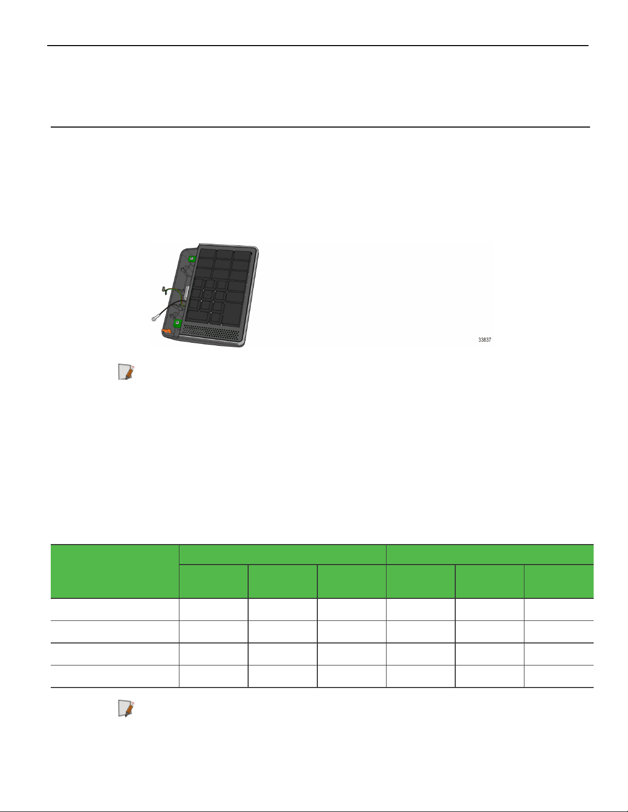
5. Install the Keypad onto the Display Collar (2 screws).
6. Route the KeypadCable through the Cable Guide on the Display Collar.
Note: Limit the amount of cable from the Cable Guide to 2.5" for the RealPOS XR7.
Page 7

X-Series Integrated Keypad 5
7. Reinstall the Display Collar on the terminal.
8. Connect the Keypad Cable and Ground Wire to the Motherboard.
Caution: Pull up and down on the cable at the Cable Guide to make sure they are
not pinched under the Display Collar.
9. Replace the Base Stand and Rear Cover assembly on the terminal.
Page 8

6 X-Series Integrated Keypad
X-Series Displays
1. Lay the terminal face down on a flat surface.
Caution: Always use a soft material (cloth, foam) to protect the display screen
when placing the terminal face down.
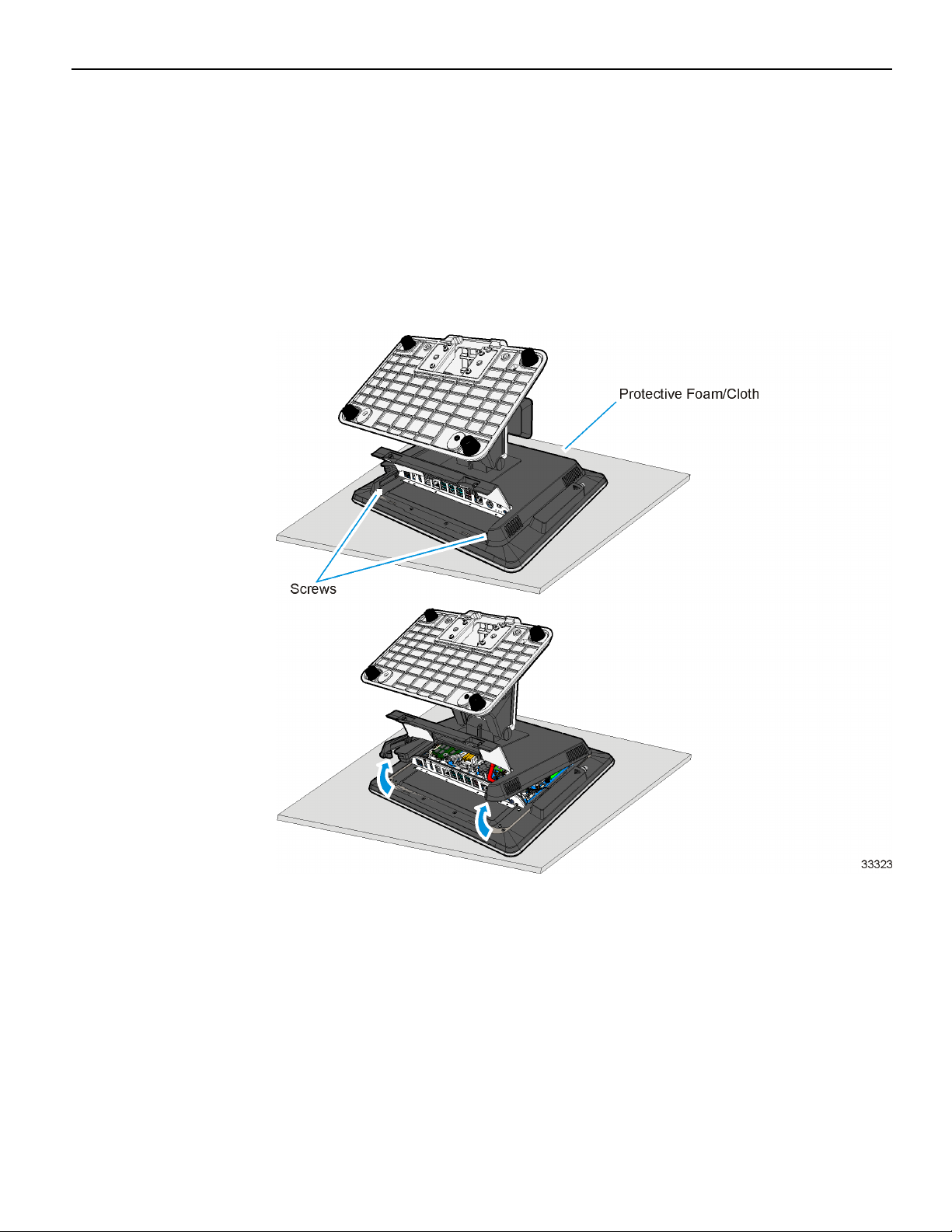
2. Remove the screws (4) that secure the Mount to the display.
Page 9

X-Series Integrated Keypad 7
3. Remove the Rear Cover screws (2).
4. Pivot the Rear Cover as shown to remove it.
5. Remove the Display Collar (9 screws).
Page 10

8 X-Series Integrated Keypad
6. Remove the Blank Plate (left side of terminal, right side is for MSR) from the Display
Collar. The plate is connected to the Display Collar with a strong adhesive. Use care
when removing it to not damage the Display Collar.
7. Install the Keypad onto the Display Collar (2 screws).
8. Route the KeypadCable through the Cable Guide on the Display Collar.
Page 11

X-Series Integrated Keypad 9
9. Reinstall the Display Collar on the terminal.
10. Connect the Keypad USB Cable to the PCB.
11. Connect the Keypad Ground Wire under the PCB mounting screw.
12. Replace the Base Stand and Rear Cover assembly on the display.
Page 12

10 X-Series Integrated Keypad
Keypad Driver
The NCRUSBUtilities package for the Keypad module is located in the following
location:
http://www5.ncr.com/support/support_drivers_
patches.asp?Class=External/Terminals\7702XR7\Windows\F149Module\display
Refer to the Readme document for the driver installation instructions.
Keypad/Keyboard Remap Utility
The NCR POSKeyboard Remap Utility provides a graphical user interface for keyboard
remapping for 5932 Keyboards, and 5953, 5954, and X-Series Dynakeys. The utility is
located in the following location:
http://www5.ncr.com/support/support_drivers_
patches.asp?Class=External/NCRKeyboard\Remap\display
Prerequisite
Refer to the Readme document for the utility installation procedure.
Patch for SLEPOS 11 SP2/SP3
Before installing the NCRPOSKeyboardRemap utility on a SLEPOS 11 SP2/SP3 platform,
ensure the following are installed:
• Retail Platform Software for Linux(RPSL)
• RPSCOMM 463 Patch
Installing the RPSCOMM 463 Patch
1. Untar the RPSCOMM_463_Patch.tar in command line as tar xvf RPSCOMM_
463_Patch.tar
2. Run the script as sh RPSCOMM_463_Patch.sh
Installing the NCRPOSKeyboardRemap
1. Run the app run script as sh NCRPOSKeyboardRemap.sh
 Loading...