

Page 1
NCR 7454 Retail Terminal
Release 2.2
Site Preparation Guide
N
C
R
B005-0000-1257
Issue C
Page 2

The product described in this book is a licensed product of NCR Corporation.
NCR is a registered trademark of NCR C orp oration.
NCR RealPOS, NCR R ealScan, and NCR EasyPoi nt are ei the r regist ere d t rademarks or trademarks of NCR
Corporation in the United States and /or other countries.
It is the policy of NCR Corporation (NCR) to improve products as new technology, components, software,
and firmware become available. NCR, therefore, reserves the right to change specifications without prior
notice.
All features, functions, and o perat ions described herein may not be marketed by NCR in all parts of the
world. In some instance s, photographs are of e q uipment prototypes. T h er efore, bef ore us ing this document,
consult with your NCR representative or NCR office for information that is applicable and current.
To maintain the quality of our publications, we need your comments on the accuracy, clarity, organization,
and value of this book.
Address correspondence to:
Manager, Information P roducts
NCR Corporation
2651 Satellite Blvd.
Duluth, GA 30096
Copyright © 2002
By NCR Corporati on
Dayton , Ohio U. S . A.
All Rights Reserved
Page 3

Preface
Safety Warnings
7454 Retail Terminal Sit e Preparation i
This is a cont ra ctua l do cu m ent . It contains import a n t warn in gs and
confers im p o rtant lega l rig hts and obligations . Y ou ar e advised to read
it carefully.
It is the respo ns ibility of the cust omer to ass u re th a t all installation
prepar at io ns a re com plete and in complia n ce wit h NCR sp e cifica t ions
and requirem e n ts and a ll app lica ble n a tio n a l, s t a t e, o r local code s,
regulatio n s, and laws.
Servicing
Caution: This product does not contain user serviceable parts.
Servicing s hould only be perform ed by a qu a lified service technician .
Fuse Replacement
Caution: For continued protection against risk of fire, replace only
with the same type and ratings of fuse.
Attention: Pour prévenir et vous protéger contre un risque de feu,
remplacer la fusible avec une autre fusible de même type, seulement.
Power Supply Cord Used as Disconnect Means
Caution: The power supply cord is used as the main disconnect
device. Ens u re tha t the socket outlet is locat e d/ ins t a lle d n e a r the
equipment and is easily a cce ssible.
Attention: Le cordon d'a lim e n ta t ion es t ut ilis é com m e interrup te u r
général. La pris e de co u ra n t doit êt re situé e ou inst a llée å prox imité du
matériel et être facile d'accés.
Page 4

ii 7454 Retail Terminal Sit e Preparation
Lithiu m Battery Warn i n g
Caution: Danger of exp losion if battery is in corre ctly replaced.
Replace only with the same or equivalent type as recommended by the
manufacturer. The battery is battery is recyclable. At the end of its
useful life , u n d e r various state and local la ws it may be illegal to
dispose of this battery into the municipal waste. Contact officials for
recycling options or proper disposal.
Attention: Il y a danger d' explosion s'il y a remp la cement incorrect de
la batterie. Remplacer uniquement avec une batterie du même type ou
d'un type recommandé par le constructeur. Mettre au rébut les
batteries us a g é es co n formé m e nt aux ins t ru ct ions du fabrica n t .
Battery D isposal (Switze rland)
Refer to Annex 4.10 of SR814.013 for battery disposal.
IT Power System
This product is su it able for co n n e ct ion t o an IT powe r sys t em wit h a
phase-to-phase voltage not exceeding 240 V.
Periphera l Usage
This terminal should only be used with peripheral devices that are
certified by th e ap p ro p ria t e sa fety agency for the country of ins t a llat ion
(UL, CSA, TUV, VDE) or those which are recommended by NCR
Corporation.
Caution: DO NOT connect or disconnect a printer, keyboard, or any
other terminal-powered peripheral while the terminal is powered on.
Doing so may res u lt in peripheral or system damage.
System Weight Considerations
Warning: The NCR 7454 terminal must be mounted securely to
prevent a hazard and must be installed in accordance with local
building codes. The wa ll on which the unit is mounted should be
able to withstand four times the we ight of the unit, which is
approximately 20 lbs. (9 kg).
Page 5

7454 Retail Terminal Sit e Preparation iii
Environmental Consciousness
NCR is demonstrating its concern for the environment by designing an
intelligen t p o we r man ag eme n t sys t em in t o th is te rminal that operates
efficiently whether the system is in a stand-alone or network
environment.
Grounding Instructions
In the event of a malfunction or breakdown, grounding provides a
path of least resistance for electric current to reduce the risk of electric
shock. This product is equipped with an electric cord having an
equipment-grounding conductor and a grounding plug. The plug must
be plugge d into a matching outlet t hat is p r ope rly installed and
ground ed in a cco rda n ce wit h all loca l co de s and ordinan ces. Do not
modify th e plug p ro vid e d – if it will n o t fit the outle t , h a v e the pr ope r
outlet installed by a qualified e le ctr ician. Im p r ope r co n n e ct ion of t h e
equipm ent -grounding con du ct o r can result in a risk of electric s h o ck .
The conductor with insulation having an outer surface that is green
with or without yellow stripes is the equipment-grounding conductor.
If repair or replacement of the electric cord or plug is necessary, do not
connect the equipment-grounding conductor to a live terminal. Check
with a qualified e lect rician or se rvice p e rs onn e l if the gro u n d ing
instruct io n s a re not co mpletely und ers to o d, o r if yo u are in doubt as to
whether the product is properly grounded.
Use only 3-wire extension cords that have 3-prong grounding plugs
and 3-pole receptacles that accept the product’s plug. Repair or replace
damaged or worn cords immediately.
Page 6

iv 7454 Retail Terminal Site Preparation
About this Book
This book prov id es site p r epar at ion information for t e rmin al
components. Peripheral component and AC wiring site preparation
information is NOT p ro vid ed in this bo ok. Th e associa t ed refe ren ce
documen ts ar e list e d in the "Related Site P r epa ra t ion Da t a" s ect io n .
This book contains the information necessary for the preparation of a
site that conforms to NCR specifications. It is very important that the
site complie s with the requirements specified in t h e docu ment because,
once the equipment has been installed, deficiencies in site preparation
or the problems caused by these deficiencies are much more difficult to
detect and correct. Further, failure to comply with these requirements
or to take proper steps to protect equipment against risks identified in
this document may cause serious damage to the equipment and to the
customer's business.
In addition to the need to comply with the requirements specified,
electrical wiring and mechanical systems must also comply with all
relevant cod e s, la ws, and regulation s.
It is importa n t th a t a cus t omer or his agent who is fully con v e rsa n t
with the special requirements of electronic equipment prepare the site.
The responsibilit y of ensurin g th a t th e sit e is pre p a re d in comp lia n ce
with this document remains with the customer.
For informa t ion an d guid a n ce pu rposes only, a list is pro v ide d, in
general terms, of those matters for which the customer is responsible.
This list is not in t ende d to be comprehensive , an d in no way mod ifie s ,
alters, or limit s the responsibility of the custom er for all aspects of
adequate site preparation.
NCR staff will be av a ilable t o a ns we r que st ion s re la tin g to the contents
of this do cum ent except where:
• A custome r has be en n ot ifie d t h a t a full or p a rt ial co ns u lt a n t service
is available a n d / or that NCR will be willing to underta ke a
prelimina ry or final site survey a n d
• The customer shall have entered into a formal contract with NCR
for provision o f the same.
Page 7

References
7454 Retail Terminal Sit e Preparation v
No comment, suggestion, or advice offered or not offered about
preparation of the site, nor any inspection of the site, whether before of
after preparation, is to be taken as approval of the location of the site
and equipment or its preparat ion. NCR will not be liable in respect to
any comment, suggestion, or advice given by its staff or in respect to
any failure to give advice.
Finally , only the cust ome r ca n kn ow the full extent o f dam ag e th at m ay
be caused to his business by reason of failure of the equipment which is
to be installed. For this reason, it is the cus to m e r's responsibility to
ascertain the extent of any possible damage to his existing or planned
business, and to effect full ins urance in for all event u a litie s.
• NCR 7454 Retail Terminal Hardware User’s Guide
(B005-0000-1256)
• NCR 7454 Retail Terminal Hardware Service Guide
(B005-0000-1342)
• NCR 7401 Web Kiosk/7454 Retail Terminal Parts Identification Manual
(B005-0000-1072)
Page 8

vi 7454 Retail Terminal Site Preparation
Page 9

Table of Contents
Introduction 1
Interpreting the Model Number..................................... 2
Related Site Preparation Data......................................... 3
Accessing Information Products.................................... 3
Customer Respo nsibilitie s 4
AC Store Wiring Requirements 5
LAN Communications 5
System Configuration Diagram 6
Physical Considerations 7
7454 Retail Terminal Sit e Preparation vii
Operating and Service Clearance Requirements...........8
Component Dimensions ................................................. 9
NCR 7454 (12.1 Inch)................................................. 9
NCR 7454 (15 Inch).................................................. 10
NCR 7454 (12.1 Inch) with PCMCIA ..................... 11
NCR 7454 (15 inch) with PCMCIA ........................ 11
NCR 7454 (12.1 Inch) w/K450 Integrated
Customer Display ................................................... 12
NCR 7454 (15 inch) w/K450 Integrated
Customer Display ................................................... 13
NCR 2183 Cash Drawer..........................................14
NCR 2189 Cash Drawer..........................................14
NCR 2113 Cash Drawer..........................................15
NCR 7158 Printer..................................................... 15
NCR 7166 Printer..................................................... 16
Page 10

viii 7454 Retail Terminal Sit e Preparation
NCR 7167 Thermal Receipt and Impact Slip
Printer....................................................................... 16
NCR 7194 Printer..................................................... 17
NCR 7196 Printer..................................................... 17
NCR 7197 Thermal Receipt Printer........................ 18
NCR 2214 Thermal Fiscal Printer........................... 18
NCR 5974 4x20 Remote Customer Display........... 19
NCR 5972-1000 2x20 Remote Customer Display. . 20
Integrated 5973 International VFD Customer
Display..................................................................... 21
5973 International VFD Customer Display........... 22
Remote 5973 International VFD Customer
Display..................................................................... 23
NCR 2336-K007 External CD-ROM Drive ............. 24
NCR 2336-K008 USB RS-232 Port Server............... 24
Component Weights ..................................................... 25
Ventilation Clearance.................................................... 26
Power Requirements..................................................... 27
7454 Power Consumption Matrix ................................ 28
Cable Routing Considerations...................................... 29
Considerations for Enclosed Installations................... 30
Thermal Test Points ................................................ 30
Service Access.......................................................... 30
Flush Wall Mount.......................................................... 31
Power Supply.......................................................... 32
Wall mount the Terminal Bracket.......................... 32
System Cables 33
Cable Illustrations ......................................................... 35
Dual Cas h Drawer, Y-cabl e.................................... 35
Ethernet, 10/100 Base-T.......................................... 35
USB, 1- or 4-Meter................................................... 36
Page 11

7454 Retail Terminal Sit e Preparation ix
Printer Interface Cables (RS-232) ........................... 37
Printer Power Cables .............................................. 38
NCR 5972-1000 Remote Customer Display and
Adapter Ca bles........................................................ 39
External CD-ROM Cable ........................................ 40
Power, AC................................................................ 41
Environmental Requirements 42
Barometric Pressure...................................................... 42
Temperature .................................................................. 42
Humidity........................................................................ 43
AC Power Line Transient Protection 1
Data Line Transient Protection....................................... 2
Page 12

x 7454 Retail Term i nal Sit e Preparation
Revisi on Re cor d
Issue Date Remarks
A Sep 00 First issue (Release 1.5)
B Feb 01 Updated to Release 2.0
C Dec 02 Updated to Release 2.2
Added 2214 printer
Page 13

7454 Retail Terminal Sit e Preparation xi
Radio Frequency Interference Statements
Federal Communications Commission (FCC)
Information to User
This equipment has been tested and found to comply with the limits for a Class A
digital device, pursuant to Part 15 of FCC Rules. These limits are designed to provide
reasonable protectio n against harmful interference when the equipment is operated in
a commercial environment. This equipment generates, uses, and can radiate radio
frequency energy and, if not installed and used in accordance with the instruction
manual, may cause harmful interference to radio communications. Operati on of this
equipment in a residential area is likely to cause interference in which case the user
will be required to correct the interference at his o wn expense.
NCR is not re sponsible for any radi o or t e le vision interference ca used by unaut horized
modification of this equipment or the substitution or attachment of connecting cables
and equipment other than those specified by NCR. The correction of interference
caused by such unauthorized m odi fication, substitution or attachment will be the
responsibility of the user. The user is cautio ned t hat changes or modifications not
expressly approved by NCR may void the user’s authority to operate the equipment.
Canadian Depar tment of Communications
This Class A digital apparatus c omplies with Canadian ICES-003.
This digital apparatus does not exceed the Class A limits for radio noise emissions
from digital apparatus set out in the Radio Interference Regulations of the Canadian
Department of Co m muni cat ion s .
Cet appareil numérique de la classe A est confor me à la nor me N MB-003 du Canada.
Le présent appareil numérique n'émet pas de bruits radioélectriques dépassant les
limites applicables aux apparei ls nu mériques de la classe A prescrites dans le
règlement sur le brouillage radioélectriques édicté par le ministrère des
Communicatio ns du Canada.
Page 14
xii 7454 Retail Terminal Site Preparation
Voluntary Control Council for Interference (VCCI)
International Radio Frequency Interference Statement
This is a Class A product. In a domestic environ me nt th is product may c ause radio
interference in which case the user may be required to take adequate measures.
Page 15

Declaration of Conformity
7454 Retail Terminal Sit e Preparation xiii
Manufacturer's Name
Manufacturer 's Address
NCR Corporation
NCR Corporation
Retail Solu t io n s Division – Atlan t a
2651 Satellite Boulevard
Duluth, GA 30096-5810
Type of Equipment
Model Number
Electrical Ratings (Input)
Informat io n Technology Equipmen t
Class 7454
100-120 V/200-240 V, 2.0 A/1.0 A, 50-60 Hz
NCR Corporation, 1700 South Patterson Boulevard, Dayton, OH 45459,
USA, declares that the equipment specified above conforms to the
referenced EU Directives and Harmonized Standards.
EU Directive Harmonized Standard(s)
89/336/EEC (EMC) EN 55022: 1987 (CISPR 22)
EN 50082-1, Part 1: 1992
IEC 801-2: 1984
IEC 801-3: 1984
IEC 801-4: 1988
73/23/EEC (Low Voltage) EN 60 950: 1992 +A1+A2:1993 +A3:1995
Director of Quality Assurance
NCR Corporation
Retail Solu t io n s Division — Atlan t a
2651 Satellite Boulevard
Duluth, GA 30096-5810
European Contact:
International IP Counsel
206 Marylebone Road
London, NW1 6LY, England
Page 16

xiv 7454 Retail Terminal Site Preparation
Page 17
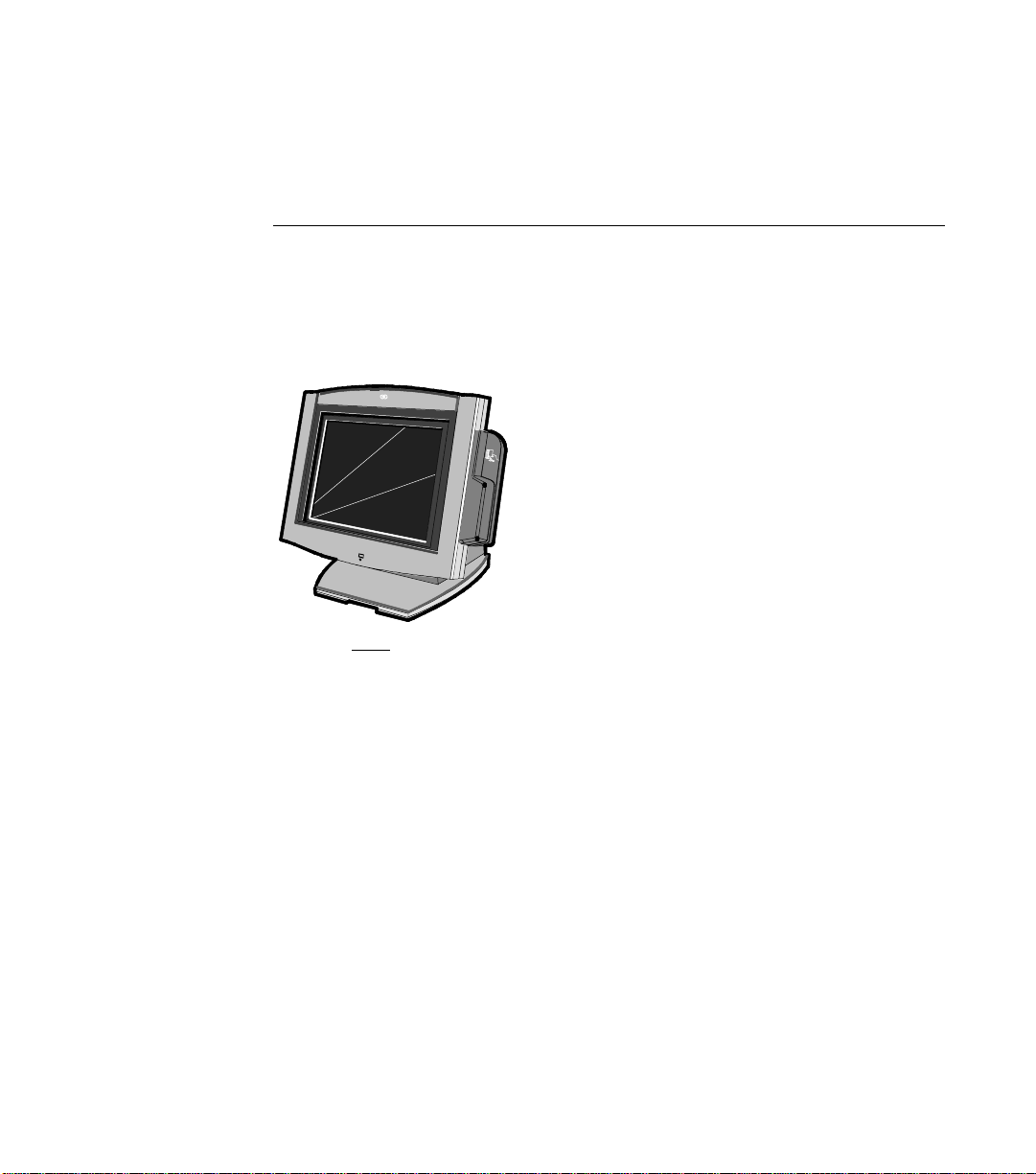
Introduction
Site Preparation
N
C
R
7454
18051
This docume n t pr ov ide s t h e information necess a r y to pre p a re a site to
NCR specificat ion s prior to installin g a terminal. The site mus t be
properly pre p a re d before t h e terminal is installed be ca u se sit e
prepar at io n de ficiencies may be d ifficu lt t o d e t ect and co rre ct a ft e r
installation.
The terminal consists of separate pieces that may be combined in a
variety of co n figurations. Cert ain combinatio ns a re mut u a lly e x clu sive.
You must determ ine the equipmen t that will a ctu a lly be installed
before proceeding with the site preparation.
Page 18

2 7454 Retail Terminal Site Preparation
Interpreting the Model Number
NCR Model 7454 22
XX
80
01
Language
Power Require d
Operating System
Processor
01 = International English
80 = 110 -240 VAC 50/60 Hz
00 = No OS
01 = Windows
03 = MS/DOS
04 = No meaning
Release 1
22 = Base Unit with 12.1" LCD
Release 2
32 = 12.1" Summa POS,
Celeron 600 MHz (G105)
Release 2.2
34 = 12.1" Summa POS,
Celeron 700 MHz (G105)
35 = 15" Summa POS,
Celeron 700 MHz (CG01)
36 = 12.1" Summa POS,
Celeron 700 MHz
37 = 12.1" Summa POS,
Celeron 600 MHz (G105)
(CG01)
18043
Page 19

Related Site Pr eparation Data
AC Power and Communications Wiring
Title Order Number
NCR Ethernet Communications Wiring Guide BST0-2118-82
NCR Terminal AC Power Wiring Guidelines BST0-2115-53
Peripherals
Title Order Number
NCR 7158 Thermal Receipt/Impact Printer B005-0000-1112
NCR 7161 Thermal Receipt Printer Owner's Guide B005-0000-1067
NCR 7166 Thermal Receipt/Impact Printer B005-0000-1002
NCR 7193 Thermal Receipt Printer Owner's Guide BD20-1439-A
NCR 7194 Thermal Receipt Printer Owner's Guide B005-0000-1094
7454 Retail Terminal Sit e Preparation 3
NCR 7196 Thermal Receipt Printer B005-0000-1170
NCR 5972 2x20 Customer Display User's Guide BD20-1372-A
Accessing Information Products
Electronic versions (PDF format) are available on the Web at the
following loca t ions:
• http:/ / in fo re t a il. AtlantaGA.NCR.COM (NCR only)
• http:// www.info.NCR .C OM (An y o n e )
Page 20

4 7454 Retail Terminal Site Preparation
Customer Responsibilities
Before the system can be installed, the customer must do or provide
the following :
• When required by NCR, provide the NCR Customer Services
representative with appropriate drawings that indicate:
− Location of the equipment
− Site wiring (power and communications, paths and leng ths)
− Location of other equipment that may generate electrical noise,
electromagnetic interference, or heat.
• Make building alterations necessary to meet wiring and other site
requirements
• Provide and install all co mm u nications cable s , wa ll jacks, specia l
connector s , a n d ass o cia t ed h a rd wa re
• Provide an d install necess a ry powe r distribution boxe s, conduits,
grounds, lightning protection devices, and associated hardware
• Make sure all applicable codes, re g u la t ions , a n d laws (in clu d in g,
but not limite d t o , e lect r ical, building , safety, and healt h ) a r e me t
• Provide and ins t all aux ilia ry power or other equipment as requ ired
• Provide storage or service areas as required
• Meet all system/unit environmental requirements
• Provide an d install floor coverings and environm e ntal systems that
limit or contro l static electricit y bu ild -u p and discharge
In general, keep the NCR equipment area free from dust, smoke, lint,
and othe r pa rt icles. Restrict sm okin g, eating, an d drin king around the
equipment. Avoid locating the equipment near other machines that
generate ink, carbon, and paper dust particles.
Finally , o n ly t h e cu s t om e r ca n kn o w the full extent of the damage that
may be caused to his business by reason of failure of the equipment
that is to be installed. For th is reas o n , it is the customer's resp ons ibilit y
to ascertain the extent of any such possible damage to his existing or
planned bus in ess, and to effect full insu rance for all eventua lit ie s.
Page 21

AC Store Wiring Requirements
The custome r must p rov ide su it able AC powe r for the ret a il te rmin a ls,
associated equipment, and devices. A dedicated unswitched power
line dedicat ed t o t h e NCR eq u ipm e n t installation is re commended.
Refer to the Workstation and Peripherals AC Wiring Guide (BSTO2115-53) for store AC wiring requirements. The AC outlet must be
installed n ea r the ret ail t e rm in a l and eas ily a cce ss ible t o the ope ra to r.
LAN Communications
The terminal supports Ethernet 10/100 Base local area network (LAN)
communication protocol. For Ethernet communications wiring
specification s , refer to the NCR Ethernet Wiring Guide (BST0-2118-82).
7454 Retail Terminal Sit e Preparation 5
Page 22

6 7454 Retail Terminal Site Preparation
System Configuration Diagram
7197
5972/5973
7194
2214
5974
7167
7196 7166 2010 Coin
2336-K008
7158
Note: 7158, 7167, 7194,
and 7197 a re avai labl e in
both RS-232 and USB.
7892
7837
RS232 (4)
2 Optional ly
Powered
USB
POS Connector Bd.
Customer Display
(Parallel)
Cash Dwr
Dispenser
Processor Board
PS/2 KBD
VGA
Ethernet
Audio
2336-K007
2260/2183/2189
2nd Cas h D rawer
(Y-Cable)
2113
18470b
Page 23

Physical Considerations
This section presents the followin g re t ail t e rmin al in fo rm a t ion:
• Operating and service clearance requirements
• Display mounting considerations
• Retail terminal and compo n ent dimensions
• Component weights
• Airflow requirements
• Power requirements
7454 Retail Terminal Sit e Preparation 7
Page 24

8 7454 Retail Terminal Site Preparation
Operating and Service Clearance Requi rements
Location Component Distance Reason
Above
2214 Printer 371 mm (14.6 in.) Clearance to raise printer cover
7158 Printer 305 mm (12 in.) Clearance to raise printer cover
7166 Printer 280 mm (11 in.) Clearance to raise printer cover
7167 Printer 305 mm (12 in.) Clearance to raise printer cover
7194 Printer 228 mm (9 in.) C learance to raise printer cover
7196 Printer 254 mm (10 in) Clearance to raise printer cover
7197 Printer 267 mm (10.5 in.) Clearance to raise printer cover
CRT Display s 50 mm (2 in.) Clearance for CR T t ilt
5972-1000 2 x 20 Display 25 mm (1 in.) Clearance for display tilt
All units 153 mm (6 in.) Service clearance
Left Side
Right Side
Front
Behind
7156 Printer 305 mm (12 in.) Clearance slip insertion
7167 Printer 305 mm (12 in.) Clearance slip insertion
All units 153 mm (6 in.) Service clearance
CRT Display 64 mm (2.5 in.) Clearance for CRT rotation
5972 2 x 20 Display 25 mm (1 in.) Clearance for display rotation
All units 202 mm (8 in.) Service clearance
7156 Printer 40 mm (1.5in.) Clearance to open printer door
Drawer unit 330 mm (13 in.) C learance to open drawer
CRT Display s 64 mm (2.5 in.) Clearance for CR T t ilt
All units 153 mm (6 in.) Service clearance
Page 25

Component Dimensions
NCR 7454 (12.1 Inch )
7454 Retail Terminal Sit e Preparation 9
400 mm
(16 in.)
370 mm
(14.5 i n.)
380 mm
(15.0 i n.)
360 mm
(14.0 i n.)
15970
Page 26

10 7454 Retail T erm i nal Site Preparat i on
NCR 7454 (15 Inch)
425 mm
(16.75 in.)
394 mm
(15.5 in.)
412 mm
(16.25 in.)
35 mm
(14.0 in.)
18134
Page 27

NCR 7454 (12.1 Inch ) w i th PCMCIA
401mm
(15.8 in.)
370 mm
(14.5 in.)
7454 Retail Terminal Sit e Preparation 11
40.7 mm
(1.6 in.)
NCR 7454 (15 inch) with PCMCIA
426 mm
(16.8 in.)
391 mm
(15.5 in.)
381 mm
(15.0 in.)
73.7 mm
(2.9 in.)
392 mm
(15.4 in.)
312 mm
(12.3 in.)
53.4 mm
(2.1 in.)
18200
14.3 mm
(0.6 in)
338 mm
(13.3 in.)
53.4 mm
(2.1 in)
18201
Page 28

12 7454 Retail T erm i nal Site Preparat i on
NCR 7454 (12.1 Inch ) w/K450 Integrated Cus tomer Display
400 mm
(16 in.)
480 mm
(19.0 in.)
366 mm
(14.3 in.)
16716
Page 29

7454 Retail Terminal Sit e Preparation 13
NCR 7454 (15 inch) w/ K450 Integrated Customer Display
425 mm
(18.75 in.)
394 mm
(15.5 in.)
480 mm
(19.0 in.)
366 mm
(14.3 in.)
16716a
Page 30

14 7454 Retail T erm i nal Site Preparat i on
NCR 2183 Cash Draw er
114 mm
(4.50 in.)
Operating and Service
Clearance for Drawer
455 mm
(17.9 in.)
450 mm
(17.7 in.)
263 mm
(10.4 in.)
18038a
NCR 2189 Cash Draw er
464 mm
(18.25 in.)
133 mm
(5.25 in.)
527 mm
(20.5 in.)
Operating and
Service Clearance
for Drawer
330 mm
(13 in.)
16676
Page 31

NCR 2113 Cash Draw er
400 mm
(15.75 in.)
96 mm
(3.75 in.)
450 mm
(17.75 in.)
7454 Retail Terminal Sit e Preparation 15
254 mm
(10 in.)
Operating and
Service Clearance
for Drawer
17310
NCR 7158 Prin ter
165 mm
(6.50 in.)
336 mm
(13.25 in)
305 mm
(12.00 in.)
229 mm
(9.00 in)
17307
Page 32

16 7454 Retail T erm i nal Site Preparat i on
NCR 7166 Prin ter
171 mm
(6.75 in.)
280 mm
(11.00 in.)
248 mm
(9.75 in.)
330 mm
(13.00 in.)
NCR 7167 Thermal Receipt and Impact Sli p Pri n ter
Top Cover Open
174 mm
(7.0 in.)
262 mm
(10.3 i n.)
316 mm
(12.5 i n.)
190 mm
(7.5 in.)
17308
296 mm
(11.7 i n.)
19711b
Page 33

NCR 7194 Prin ter
7454 Retail Terminal Sit e Preparation 17
85 mm
(3.30 in.)
157 mm
(6.20 in.)
NCR 7196 Prin ter
108 mm
(4.25 in.)
146 mm
(5.75 in.)
130 mm
(5.10 in.)
212 mm
(8.3 in.)
187 mm
(7.4 in.)
16492
254 mm
(10.00 in.)
140 m
(5.50 in.)
17306
Page 34

18 7454 Retail T erm i nal Site Preparat i on
NCR 7197 Thermal Receipt Printer
Top Cover Open
256 mm
(10.1 in.)
156 mm
(6.25 in.)
184 mm
(7.25 in.)
146 mm
(7.75 in.)
NCR 2214 Thermal F i scal Printer
175 mm
(6.9 in.)
278 mm
(11 in.)
371 mm
(14.6 in.)
210 mm
(8.3 in.)
19712c
18542
Page 35

NCR 5974 4x20 Remote Customer Display
7454 Retail Terminal Sit e Preparation 19
110 mm
(4.25 in.)
95 mm
(3.75 in.)
180 mm
(7 in.)
506 mm
(22.1 in.)
95 mm
(3.75 in.)
50 mm
(3.5 in.)
16673
Page 36

20 7454 Retail T erm i nal Site Preparat i on
NCR 5972-1000 2x20 Rem ote Customer Display
119 mm
(4.7 in.)
(3.75 in.)
262 mm
(10.3 in.)
30 mm
(1.2 in.)
506 mm
(22.1 in.)
95 mm
(3.75 in.)
1570895 mm
Page 37

7454 Retail Terminal Sit e Preparation 21
Integrated 5973 International VFD Customer Display
110 mm
(4.3 in.)
95 mm
(3.75 in.)
262 mm
(10.3 in.)
45 mm
(1.8 in.)
350 mm
(13.8 in.)
95 mm
(3.75 in.)
17236a
Page 38

22 7454 Retail T erm i nal Site Preparat i on
5973 International VFD Customer Display
110 mm
(4.3 in.)
95 mm
(3.75 in.)
262 mm
(10.3 in.)
45 mm
(1.8 in.)
556 mm
(21.9 in.)
95 mm
(3.75 in.)
17236
Page 39

7454 Retail Terminal Sit e Preparation 23
Remote 5973 International V F D Custom er Display
110 mm
(4.3 in.)
262 mm
(10.3 in.)
178 mm
(7.0 in.)
158 mm
(6.2 in.)
173 mm
(6.8 in.)
45 mm
(1.8 in.)
17237
Page 40

24 7454 Retail T erm i nal Site Preparat i on
NCR 2336-K007 Extern al CD-ROM Drive
155 mm
Note: Allow 75 mm (3 in.) clearance in the back of the NCR 2336-K007
External CD-ROM Drive for connector and cable clearance.
(6.1 in.)
218 mm
(8.6 in.)
23 mm
(0.9 in.)
16951
NCR 2336-K008 USB RS-232 Port Server
183 mm
(7.2 in.)
111 mm
(4.4 in.)
26 mm
(1.0 in.)
16950
Page 41

Component Weights
The following table shows the weight of the 7454 retail terminal
components.
Retail Terminal Component kg lbs.
2189 Cash Drawer 9.5 20.9
7454-K005 Cash Drawer 11.4 25.15
7454-K453 Remote Customer Display 0.7 1.5
5972-1000 Remote Customer Display 0.7 1.5
7156 Multifunction Printer 4.1 9.1
7158 Receipt/Impact Printer 4.8 10.5
7166 Receipt/Impact Printer 5.6 12.3
7454 Retail Terminal Sit e Preparation 25
7167 Thermal Receipt & Impact Slip Printer
7194 Thermal Receipt Printer 1.3 2.8
7196 Thermal Receipt Printer 1.8 3.4
7197 Thermal Receipt Printer 1.53 3.4
2214 Thermal Fiscal Printer 3.6 7.9
2336-K007 External CD-ROM Drive 0.6 1.3
2336-K008 USB RS-232 Port Server 0.3 0.6
4.5 10
Page 42

26 7454 Retail T erm i nal Site Preparat i on
Minimu m Ve rt ic a l
Minimum Horizontal
Ventilation Clearance
The following illu stration shows t h e minimum clea ra n ces for proper
cooling.
25 mm
(1 in.)
76 mm
(3 in.)
16418
Page 43

Power Requirements
Core module contain a three-wire, single-phase, selectable 120/240 volt
AC, 85 Watt power supply. The supply powers the retail terminal,
scanner, VFD display, keyboard, USB interface, cash drawer,
integrated speakers, and PCMCIA cards.
The following t a bles show operating sp e cificat ion s for the power
supply.
Maximum Input Power Specifications
Voltage Ranges 90 - 136 VAC 198 - 257 VAC
Frequency 50/60 Hz 50/60 Hz
Current (A) 2.5 1.25
Power (W) 85 85
Power Factor (typical) 0.48 0.38
7454 Retail Terminal Sit e Preparation 27
120 Volt 240 Volt
Typical Power Requirements
7454 Configuration Retail Terminal Condition Amps Watts
120 Volt
12.1” LCD
600 MHz PIII
Soft OFF (Sleep Mode) 0.33 39.6
Idle (Power On) 0.51 61.2
Active, during scanning 0.55 66
240 Volt
12.1” LCD
600 MHz PIII
Soft OFF (Sleep Mode) 0.17 39.6
Idle (Power On) 0.26 61.2
Active, during scanning 0.28 66
Page 44

28 7454 Retail T erm i nal Site Preparat i on
7454 Power Co ns um pt io n Matr i x
The following table is provided as a reference of the power
consumption of the peripherals available on the 7454
Note: A ll power data listed in table belo w is ra t ed in ampera g e.
Item Description 3.3VDC 5.0VDC 12VDC Requires external power source
Power Supply (8 5 Watts 49 7-041550 3)
Summa POS Moth erb oard with CPU , & up
to 128MB M em ory
Personality Board - 7454
Power av ailable for Peripherals
4.10 7.80 2.70
2.00 3.00 0.04
0.20
2.10 4.60 2.66
LCDs: Samsung TFT (006-8603280 or
006-8604312) , or Sharp DSTN 006-8601845
MSR Modules
Touch Screen feature
Remote sp ea kers
Cash Draw er
(no more then one simul taneous op en ing)
Printers (always require brick)
2337-K002 Samp o 12. 1" c ol or LCD -
analog interface (497-0415562)
7452-K419 COMPAL 15" Color CRT
(497-0414127)
External CD-ROM Drive
(Parallel, 2336-K024, 497-0416287)
7880 Scanner/Scale
7872 Scanner/Scale
7875 Bi-Optic Scann er
7452-K891 CCD Hand Held Scanner (008-0221512)
Safety - Contingency
Power av ailable for Peripherals
Hard Disk Drive 2.5"
CD-ROM (TEAC, 24X) 006-8603220 C
Keyboards
Display 4x20 VFD Powered from Parallel Port
Display 4x20 VFD Powered fro m Serial Port
Display 4x20 VFD Int'l, Powered from
Parallel Port (008 -0 22 1541)
Display 2x20 VFD Powered fro m Serial Port
USB to 4 port RS-232
0.29 0.80
0.00 0.00 0.00
0.25
0.33
0.00 0.00 0.00
0.00 0.00 0.00
0.00 0.00 0.00
0.20 0.50 0.30
1.61 3.85 1.23
0.50
1.00
0.20
1.00
0.45
2.00
0.50
0.50
X
X
X
X
X
X
X
X
Page 45

7454 Retail Terminal Sit e Preparation 29
Item Description 3.3VDC 5.0VDC 12VDC Requires external power source
(2336-K008, 497-0413014)
USB to 2 port RS-232
(2336-K012, 497-0413710)
PCMCIA Controller
IRDA
5992 Signature capture device (497-0417590)
5945 Electronic Payment Device (497-0411818)
7837 Hand held Scanner
7892 Pres entation Sc ann er
7882 Scanner
0.40
0.50
0.50
0.80
0.50
0.30
0.50
0.60
Cable Rout in g Con si der at io ns
The Core Mo dule 's ca ble co n n e ct or s a re loca t e d on the un d er side of the
Core Module, under the Cable Cover. Cables can be routed out the
back of the Ta ble- To p Mount.
Cable Cover
Thumb Screw
15968
Page 46

30 7454 Retail T erm i nal Site Preparat i on
Considerations for Enclose d Installation s
Thermal Test Points
With the term in al ins t a lled in th e enclosure, verify that the temperature
does not exceed 45
o
C (115o F) in the operating environment. Thermal
test points are shown below:
Thermal Test Points
(Case over Hard Drive and Processor)
18055a
Note: For terminal servicing information refer to NCR 7454 Retail
Terminal Hardware Service Guide (B005-0000-1342).
Service Access
The enclos ure must provide acce ss to certain locat ions for service
purposes.
Page 47

Flush W all Mou nt
The 7454 can be mounted flush against a wall. The following shows
mounting configuration and brackets:
7454 Retail Terminal Sit e Preparation 31
Flush Mount w/Power Supply
Mounted on the Outside Wall
Flush Mount w/Power Sup pl y
Mounted on the Inside Wall
Note: Refer to the Cable Illustrations section for cable pass-through
hole sizes.
16683
Page 48

32 7454 Retail T erm i nal Site Preparat i on
Power Supply
152 mm
(6 in.)
102 mm
(4 in.)
57 mm
(2.25 in.)
17406
Wall mount the Terminal Bracket
Drill a hole in th e wall for t h e cables if you are mounting t he power
supply on the opposite side of the wall.
Flush Mounting Brack et
Cable Routing
Wall Plate
Cable Routing
(through wall)
16684
Page 49

7454 Retail Terminal Sit e Preparation 33
15.2 m/50 ft.
System Cables
Cable Type Cable Name NCR Part No. Corp. ID No. Approximate
Cable Length
Cash Drawer Dual Drawer, Y cable 497-0409394 1416-C372-0006 0.6 m/2 ft.
Communications Ethernet, 10/100Base-T
USB 497-0415949 1416-C528-0010 1 m/3.3 ft.
USB 497-0415950 1416-C528-0040 4 m/13 ft.
Displays Remote Customer Display
(Parallel)
Parallel I/ F Cable
(adapter cable)
Power U.S. – Straight 006-1009037 1416-C325-0030 3 m/10 ft.
U.S. – Twist-lock 250-0023191 1416-C419-0030 3 m/10 ft.
Intl. – straight 'bm' power 006-8601010 1416-C323-0030 3 m/10 ft.
Intl. 006-1012224 1416-C411-0030 3 m/10 ft.
SEV – straight 'bm' power 006-8601011 1416-C408-0030 3 m/10 ft.
UK – straight 'bm' power 006-8601012 1416-C321-0030 3 m/10 ft.
UK – Rectangular 006-8601012 1416-C409-0030 3 m/10 ft.
Austra lia – stra ig h t ' bm'
power
Japan – Power Cord (US
Style with T-Mark)
Japan – Twist-lo ck , straight
'bm' power
Printer Interface 7193/7194/7158 Printer 497-0408349 1416-C359-0007 0.7 m/2 ft..
497-0407943 1401-C266-0040 4 m/13 ft.
497-0409379 1416-C266-0152 15.2 m/50 ft.
7161 Printer 497-0407427 1416-C337-0010 1 m/ 3.3 ft.
497-0407429 1416-C337-0040 4 m/13 ft.
497-0407430 1416-C337-0152 15.2 m/50 ft.
497-0409379 1416-C266-0152
497-0008623
(Unshielded)
497-0405676 1416-C278-0040 4 m/13 ft.
497-0411000 1416-C472-0006 0.6 m/2 ft.
006-8601019 1416-C322-0030 3 m/10 ft.
006-8604879 1416-C608-0030 3 m/10 ft.
006-8601001 1416-C393-0030 3 m/10 ft.
Page 50

34 7454 Retail T erm i nal Site Preparat i on
Cable Type Cable Name NCR Part No. Corp. ID No.
Printer Extender
Drop Cabl e s
(7453-K641)
7193/7194 Printer 497-0411816 1416-C418-0040 4 m/13 ft.
Printer Power
7161/7166/7196
497-0411815 1416-C417-0040 4 m/13 ft.
Printer/Workstation
7193 Printers 497-0405937 1416-C286-0010 1 m/3.3 ft .
Approximate
Cable Length
Supply
7194 Printer 497-0405945 1416-C286-0040 4 m/13 ft.
Page 51

Cable Illustrations
Dual Cash Drawer, Y-cable
497-0409394
7454 Retail Terminal Sit e Preparation 35
Cash
DWR. #1
Cash
DWR. #2
16 mm
(0.625 in.)
Ethernet, 10/100 Base-T
Modular
8-Pin
Plug
19 mm
(.75 in.)
Access Hole Diameters
497-0008623
Access Hole Diam eters
19 mm
(.75 in.)
51 mm
(2.0 in.)
15808
Modular
8-Pin
Plug
16298
Page 52

36 7454 Retail T erm i nal Site Preparat i on
USB, 1- or 4-Meter
4
3
2
1
Type A
USB
P1
497-0415949 (1 meter)
1416-C528-0010
498-0415950 (4 meter)
1416-C528-0040
Access Hole Diameters
Type B
USB
2
P2
1
3
4
6.4 mm
(0.25 in.)
15 mm
(0.63 in.)
18433
Page 53

Printer Interface Cabl es (RS -232)
7161/7166/7196
9-pin
D-shell
Receptacle
497-0407427 - 1 m
497-0407429 - 4 m
497-04 07430 - 15 m
7454 Retail Terminal Sit e Preparation 37
25-pin
D-shell
Plug
Workstation
RS-232 Port
7193/7194/7158
Receptacle
Workstation
RS-232 Port
38 mm
(1.5 in.)
9-pin
D-shell
38 mm
(1.5 in.)
Access Hole Diameters
497-0408349 - 0 .7 m
497-0407943 - 4 m
497-0409379 - 1 5 m
Access Hole Diameters
Printer
63.5 mm
(2.5 in.)
13224
9-pin
D-shell
Receptacle
Printer
38 mm
(1.5 in.)
13223
Page 54

38 7454 Retail T erm i nal Site Preparat i on
16293
NCR 7161 Printer with 7454-K641 Cable Extender
Workstation
RS-232 Port
Workstation
RS-232 Port
9-pin
D-shell
Receptacle
25-pin
D-shell
Plug
7453K641
497-0411815 - 4m
1416-C417-0040
NCR 7193 Printer with 7454-K641 Cable Extender
9-pin
D-shell
Receptacle
497-0411815 - 4m
1416-C417-0040
25-pin
D-shell
Plug
7453K641
Printer Power Cables
25-pin
D-shell
Receptacle
25-pin
D-shell
Receptacle
497-0411816 - 4m
9-pin
D-shell
Plug
7161
Printer
497-0411815 - 4m
1416-C417-0040
16294
25-pin
D-shell
Plug
7193/
7194
Printer
1416-C418-0040
NCR 7193 Printer
6-pin
Mini-DIN
Connector
To
Printer
Integr ated Cable 497-0405937 - 1m
Remote Cable 497-0405945 - 4m
Access Hole Diameters
12.6 mm
(0.5 in.)
19 mm
(0.75 in.)
6-pin
Microfit
Receptacle
To 7453
Printer
Power
15398
Page 55

7454 Retail Terminal Sit e Preparation 39
NCR 5972-1000 Rem o te Customer Displ ay an d Ad ap ter Cab les
Parallel I/F Cable
497-0411000 - 0.6 M
To 7454
Cust. Display
Port
25-pin
D-Shell
Receptacle
57.1 mm
(2.25 in.)
497-0405676 - 4 M
1416-C278-0040
To Power
8-pin
Brick
Microfit
Receptacle
Access Hole Diameters
19 mm
(0.75 in.)
24-pin
Microfit
Receptacle
To
Customer
Display
25 mm
(1.0 in.)
16291
Page 56

40 7454 Retail T erm i nal Site Preparat i on
External CD-R OM Cable
25-pin
D-Shell
Receptacle
To CD-ROM
Parallel
Connector
57 mm
(2.25 in.)
External Parallel Cable
25-pin
D-Shell
Receptacle
497-0413011 - 0.6 M
1416-C464-0006
To CD-ROM
Power
SMK
Connector
2 mm Plug
Access Hole Diameters
12 mm
(0.5 in.)
497-0411000-0.6 M
1416-C472-0006
28-pin
Sub-Miniture
D-Plug
31 mm
(1.25 in.)
28-pin
Sub-Miniture
D-Plug
To 7454
Cust. Display
Port
16959
To CD-ROM
Parallel
Connector
57 mm
(2.25 in.)
Access Hole Diameters
Cust. Display
31 mm
(1.25 in.)
To 7454
Port
17390
Page 57

Automatic Change Dispenser Serial Cable
7454 Retail Terminal Sit e Preparation 41
P1
5
1
9
6
Power, AC
9-Pin
D-shell
Receptacle
006-1009037
Access Hole Diam eter
497-0404832
Workstation
45 mm
(1.75 in.)
25-pin
D-shell
Plug
P2
13
25
1
14
18056
15405
Page 58

42 7454 Retail T erm i nal Site Preparat i on
Environmental Requirements
Barometric Pressure
The 7454 Retail Terminal is designed to operate within the following
barometric p re ss u re con d itio ns :
• Maximum operating altitude: 3,000 m (9,843 ft.)
• Operating range of pressure: 105 kPa to 69 kPa (15.2 lb/in. to 10.0
lb/in.)
Temperature
The 7454 Retail Terminal is designed to operate over the temperature
ranges shown belo w. Continuous ope ra t ion m us t be av o ide d, h o wev e r,
at or near the temperature extremes, or in locations where temperature
changes exceed the temperature restrictions.
Temperature Parameter Restriction
Operating
Storage
Shipping
Dew Point
5oC to 45oC (41oF to 113oF), dry bulb
-10oC to 50oC (14oF to 122oF), three months
-40oC to 60oC (-40oF to 140oF), one week
26oC (79oF) maximum
Page 59

Humidity
7454 Retail Terminal Sit e Preparation 43
The 7454 Retail Terminal is designed to operate within the humidity
ranges shown belo w. Continuous ope ra t ion m us t be av o ide d, h o wev e r,
at or near th e hum idit y lim it s, or in locations wher e humidity changes
exceed the humidity restrictions. In no case should the 7454 Retail
Terminal be subjected to condensation.
Humidity Type Restriction
Relative 10% to 90%
Maximum change rate 10%/60 minutes
Storage 10% to 90% relative humidity, three months
Shipping 5% to 95% relative humidity, one week
Page 60

44 7454 Retail T erm i nal Site Preparat i on
Page 61

Appendix A: Transient Protection
AC Power Line Transient Protection
In the process of power distribution, transient electrical energy
(including , but not limited to, lig h t n ing s t rik es , in te rmittent short
circuits, and switching transients) can be introduced onto power lines.
Such transient energy can be very damaging to electronic hardware,
and can also cause data corrupt io n . Und e r t h es e circumstan ces, NCR
recommends the use of AC power transient suppressors. Such
protection devices are intended to guard against power line transients
that can result in hardware damage and various system or program
errors.
Improvement of any deficiencies in power quality is a customer
responsibilit y. Malfunct io n a n d/or co mp o n e n t failu re as a resu lt o f
power quality p r oble ms is not covered by the NC R Maint ena n ce
Agreement . NCR acce p ts no lia bility for any such occurren ce o r for it s
consequences.
When power transient suppression is required, the suppressors used
should me e t the following minimu m re q u irem e n t s:
• Dissipate energy to match the appropriate application categories as
defined by IEEE Standard 587.
• Be of the volta g e limit in g (clipping), or tracking filter t yp e. The
suppressor must not clamp the voltage to zero, and must selfrecover after the passage of the transi ent. The supp ressor may b e of
the hybrid type construction that makes use of various technologies
in order to meet speed and dissipation requirements.
• Upon failure, exh ibit a pos it iv e indication of its failure such as a
blown fuse or tripped breaker.
Page 62

A-2 A ppendi x A: Transient Protection
• Be listed by the accepted safety organization for the country
involved (UL , C S A, VDE, E TL, a n d so on) and th e ins t a llat io n must
conform to local, state, and national electrical codes and
regulations.
Data Line Transient Protection
The nature of the transient phenomenon may extend to the data
communication lines connected to this equipment. It is the
responsibilit y of the custome r t o install and connect a data lin e
transient suppression system to correct or prevent any deficiencies.
Such systems must meet the following minimum requirements:
• Be of the voltage limiting type and mus t self-re cov e r a ft er passage
of the transient.
• Insert less than 5 ohms resis tance a n d minimal inductive and
capacitive lo ad in g at the operat ing fre q uency for data lines, in
order to avoid signal degradation.
• Be insta lled in accord a n ce with all applicable loca l, state, and
national electrical codes and regulations.
Note: I n certain countries, NCR is able to supply both power and data
line transient suppress o rs a s well a s a com p re h ensive line of power
conditioning equipment. For application data, contact your NCR
Customer Services Division Representative.
Page 63

Page 64

Page 65

Index
—2—
2113 Cash Drawer, 15
2183 Cash Drawer, 14
2189 Cash Drawer, 14
2214 Thermal Fiscal P, 18
2336-K007 External CD-ROM
Drive, 24
2336-K008 USB RS-232 Port
Server, 24
7454 (12.1 Inch) with PCMCIA,
11
7454 (15 Inch), 10
7454 (15 inch) w/K450
Integra t e d Customer Display,
13
7454 (15 inch) with PCMCIA, 11
7454 Power Consumption
Matrix, 28
—A—
—5—
5972-1000 2x20 Remote
Customer Display, 20
5973 International VFD
Customer Display, 22
5974 4x20 Remote Customer
Display, 19
—7—
7158 Printer, 15
7166 Printer, 16
7167 Thermal Receipt and
Impact Slip Printer, 16
7194 Printer, 17
7196 Printer, 17
7454 (12.1 Inch), 9
7454 (12.1 Inch) w/K450
Integra t e d Customer Display,
12
AC Power Line Transient
Protection, 1
—B—
Barometric Pressure, 42
—C—
Cable Illu strations, 35
Cable Rou t ing Cons id er at io n s,
29
Clearance Requirements, 8
Commu n ica t io n s, 5
Component Weights, 25
Conside ra tio ns fo r Enclosed
Installations, 30
Custom e r Responsibilities , 4
Page 66

—D—
—O—
Data Line Transient Protection,
2
Dimensions, 9
—E—
Environmental Requirements,
42
Barometric Pressure, 42
Humidity, 43
Temperature, 42
—F—
Flush Wall Mount, 31
—H—
Humidity, 43
—I—
Integrated 5973 International
VFD Customer Display, 21
—M—
Model Number, 2
Operating Clearance
Requirements, 8
—P—
Power Requirements, 27
Power Supply, 32
—R—
Remote 5973 International VFD
Customer Display, 23
—S—
Service Clearance
Requirements, 8
System Cables, 33
System Configuration Diagram,
6
—T—
Thermal Test Points, 30
Transient Protection
AC Power Line, 1
Data Line, 2
—N—
NCR 7197 Thermal Receipt
Printer, 18
—V—
Ventilation Clearance, 26
—W—
Wiring Requirements, 5
Page 67

Page 68

B005-0000-1257 Dec 2002 Printed on recycle d paper
 Loading...