

Page 1

7403-K150
Biometrics Module
(Fingerprint Recognition)
Kit Instructions
Issue B
Page 2

A
May 2009
First issue
Revision Record
Issue Date Remarks
Page 3
Introduction
27625
Biometrics Module
27624
Biometrics Module
Screw, 4-40 x 0.625 Pan Hd
1
This kit provides an integrated U.are.U® Biometrics module for the 7403 terminal,
providing fingerprint recognition capabilities.
Kit Contents
Page 4
2
26124
Security Key
Front Base Cover
Installation Procedures
Caution: Static Electricity Discharge may permanently damage your system.
Discharge any static electricity build up in your body by touching your computer’s
case for a few seconds. Avoid any contact with internal parts and handle cards only
by their external edges.
1. Disconnect power to the terminal.
Caution: Disconnect the AC power cord before disassembling the terminal. The
ON/OFF switch does NOT remove power to the unit.
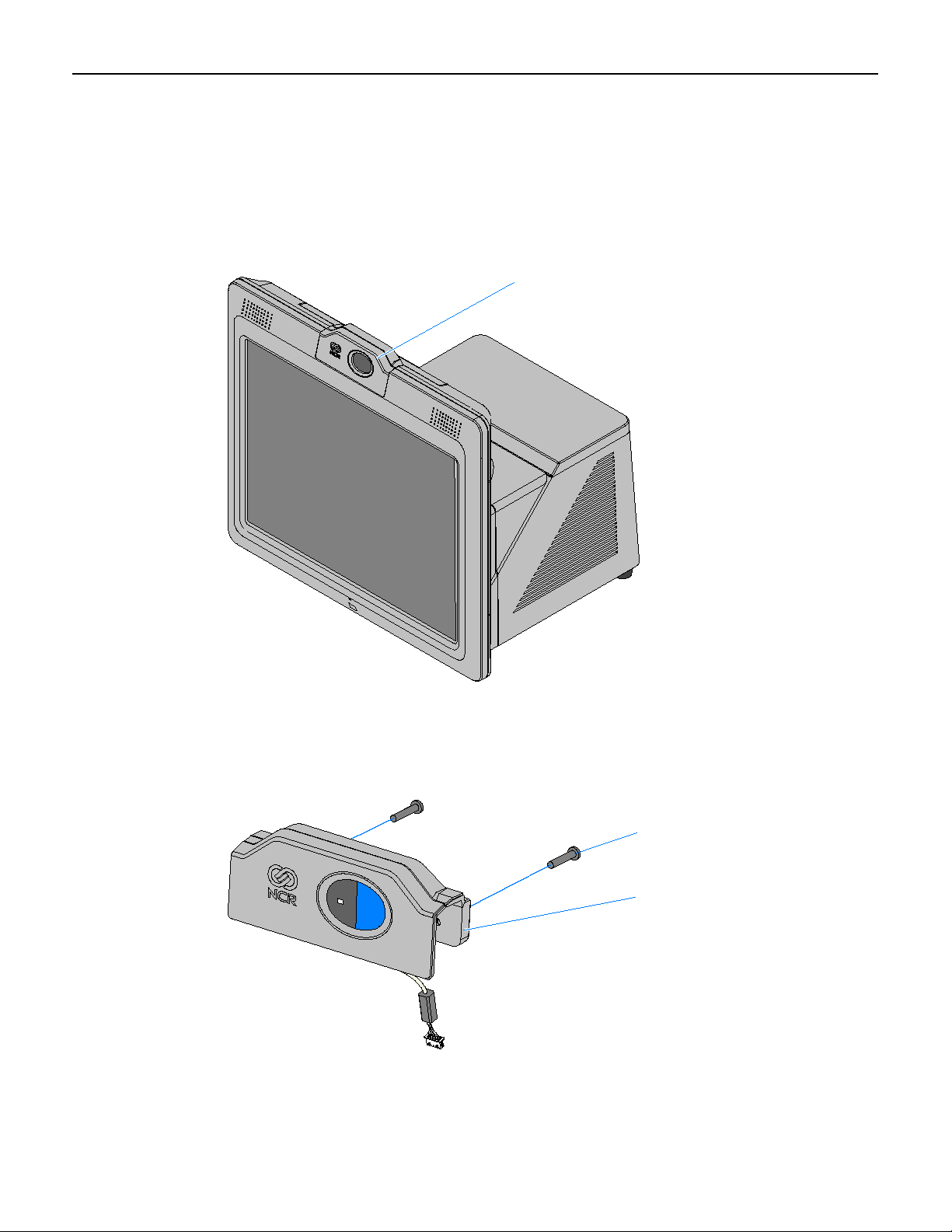
a. Remove the Front Cover.
b. Insert the Security Key and turn it 90 degrees clockwise.
Page 5
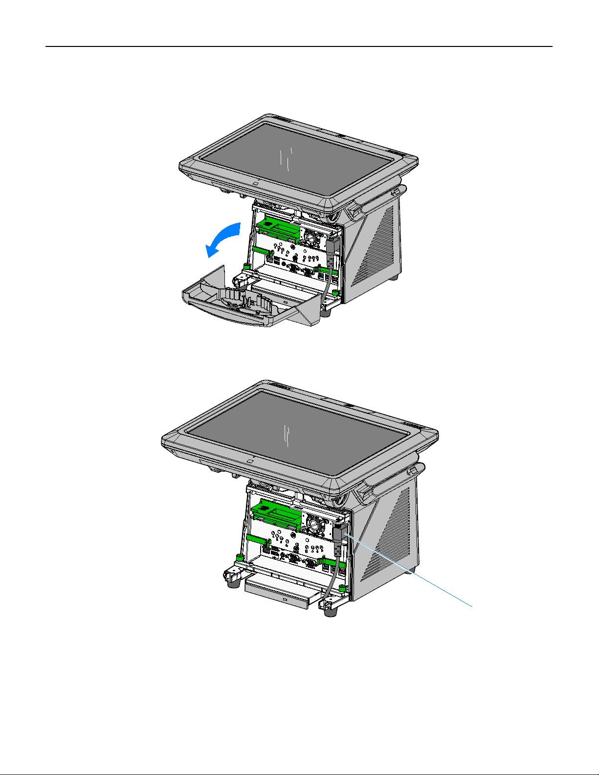
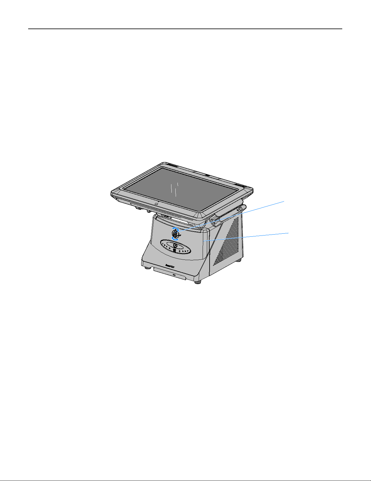
c. Pivot the top of the Front Base Cover toward the front of the unit and remove
26032
26135
AC Power Cord
it from the terminal.
3
d. Disconnect the Power Cord from the Power Supply.
Page 6

4
26464
Display Cable
Thumbscrews
2. Disconnect the Display Cable.
3. Loosen the Display thumbscrews (2).
Page 7

4. Depress the Display Release Latches (2) and slide the Display Head toward the
26151a
Display Latches
rear of the terminal to disengage it from the chassis.
5
Page 8

6
27639
Top Access Cover
27638
Top Insert Cover
5. Lay the Display Head on a flat, non-scratch surface to avoid scratches to the
Touchscreen and Front Bezel.
6. Loosen the captive screws (2) that secure the Top Access Cover and then remove
the cover from the Display Head.
7. Remove the Top Insert Cover from the Display Head 2 screws).
Page 9

8. The below illustration shows how to fold the cable. It is easier to pre-fold the cable
27641
Cable Loop
27626
Biometrics Module Back
before assembling the module onto the Display Head. Fold the cable with a loop
that routes through the slot in the Biometrics Module Back.
9. Separate the Biometrics Module Back from the Biometrics Module Assembly by
gently pivoting the bottom edges of the Biometrics Module Front and Back as
shown below to unlatch the pieces at the top eges.
7
Page 10

8
27640
Biometrics Module Back
Biometrics Module Front
Plastic Insulator
27642
Biometrics Module
Cable Connector
10. Install the Biometrics Module Assembly onto the Display Head.
a. Position the front portion of the Biometrics Module Assembly on the Display
Head. There is a square slot in the Rear Cabinet that the cable is routed
through.
Note: Make sure the Plastic Insulator is installed.
b. Secure the assembly with the Biometrics Module Back (2 screws).
11. Connect the Biometrics Module Cable to the Display Head.
Page 11

12. Reassemble the unit using the reverse order.
a. Install the Top Access Cover
b. Install the Display Head onto the base
c. Connect the Display Head Cable
d. Connect the Power Cord
e. Install the Front Base Cover.
Driver/SDK Download
The driver and SDK can be downloaded from the Digital Persona web site. Download
the 4500 model items.
http://www.digitalpersona.com/DigitalPersona-U-are-U-Software-Development-Kits(SDKs)/
Digital Persona provides the SDK for a fee. The provider of the POS application has
the rights to distribute the DP Run Time Engine (RTE).
9
Page 12

10
Using the Biometrics Module
Guidelines for Fingerprint Registration
High quality fingerprint templates are imperative for the security of the biometric
security system. Low quality fingerprint templates can impact future read rates.
Therefore, using the Biometrics Module should be done very carefully. In case of
inexperienced users who are using the module for the first time, the process should be
assisted (guided) by an administrator or experienced user.
Procedures
Prior to using the module make sure the fingerprint sensor is clean: See the Sensor
Cleaning Procedure section.
Normal Usage
Place your finger flat and straight on the sensor. If this is not possible, try to place
your finger on the sensor in the same angle every time.
Registering a New Fingerprint
Multiple images (4) are required to register a fingerprint into the system. Therefore,
great care should be taken to place the same part of the fingerprint on sensor every
time. The best way to achieve this is to:
1. Lean the finger comfortably against the front of the housing with the fingertip
raised.
2. Bend the tip of the finger down to touch the sensor.
3. After the fingerprint image is captured (light blinks), lift tip of the finger up.
Location of the Fingerprint on the Sensor
The core of the fingerprint must be centered on the sensor.
Page 13

11
The Biometric Module algorithms automatically recognize it if the fingerprint is
placed too low, too high, or too far to the left or right side of the sensor and then
provide the user with feedback to improve the fingerprint placement.
Pressure: Put your finger gently on sensor. Do not press it down too firmly (or too
lightly). Exert approximately the same amount of pressure as if you were pressing a
doorbell button.
Choose the correct finger: To obtain a good fingerprint image, and a good fingerprint
template, the print itself must be a good quality. A damaged fingerprint, e.g. with
cuts, will not result in a high quality template. The most suitable fingers to use are the
index finger or middle finger. The small finger is not recommended because it
typically contains fewer details.
Page 14

12
Troubleshooting & Cleaning
Troubleshooting
If the reader is having difficulty acquiring a scan of your fingerprint, consider the
following:
• The reader window may need cleaning, see Cleaning the Reader.
• You may not be touching the reader correctly. In order for the reader to acquire a
good scan of your fingerprint, you must place the pad of your finger—not the
tip—in the center of the oval window, and apply gentle, even pressure. Do not roll
your finger. Pressing too hard distorts your fingerprint. Pressing too lightly does
not expose a large enough area of your fingerprint.
• Make sure you hold your finger on the reader until you see the reader light blink.
This can take longer if the skin is dry. Then, lift your finger. Although you may
use any finger with the reader, your index finger of either hand works best.
• If the reader is capturing your fingerprint (as indicated by the reader blink) and
you have tried all the above suggestions, you may need to re-register your
fingerprint.
Cleaning the Reader
Depending on the amount of use, the reader window may need to be cleaned
periodically.
To clean it, apply the sticky side of a piece of adhesive cellophane tape on the window
and peel it away.
Under heavy usage, the window coating on some readers may turn cloudy from the
salt in perspiration. In this case, gently wipe the window with a cloth (not paper)
dampened with a mild ammonia-based glass cleaner.
Page 15

Reader Maintenance Warnings
There are several things you should never do when cleaning or using the reader
• Do not pour the glass cleaner directly on the reader window.
• Do not use alcohol-based cleaners.
• Never submerge the reader in liquid.
• Never rub the window with an abrasive material, including paper.
• Do not poke the window coating with your fingernail or any item, such as a pen.
Caution: The fingerprint reader is for indoor home or office use only.
USB Controller Configuration
Check the USB controller configuration using the following steps:
1. Click Start → Settings → Control Panel → System.
2. Click the Hardware tab.
13
3. Click the Device Manager button.
• In the Device Manager verify that you have an entry called Universal Serial Bus
controller.
• If this entry does not exist, you need to contact the vendor of your USB
hardware for information on how to correctly configure the USB controller.
4. If the entry does exist, continue to next step.
5. Open the Universal Serial Bus controller icon by clicking on the plus (+) sign to
the left of the icon. Verify that there is a USB Root Hub icon and an icon for the
USB Port.
• If either of these icons is missing or have exclamation points or red X's on
them, contact the computer manufacturer for information on correctly
configuring the USB Controller.
• If these settings appear to be correct, the sensor may be faulty and should be
replaced.
 Loading...