

Page 1

USER MANUAL
Navigon Bluetooth
CSR BC5-MM Solution
Bluetooth Module
Page 2

Contents
Section One: Introduction 1
1.1 Features 1
1.2 Hardware Requirements 1
Section Two: Bluetooth Installation 3
2.1 ActivePerl Installation 3
2.2
Bluetool Installation
2.3 Driver in BTWUSB
The information contained in this manual has been verified at the time of this manual printing. The
manufacturer reserves the right to make any changes and improvements in the product described in this manual
at any time and without notice.
All registered trademarks are the property of their respective owners.
Page 3
Section One: Introduction
This module is with CSR BlueCore5-Multimedia External solution. It is a single-chip radio and
baseband IC for Bluetooth 2.4GHz systems. When used with the CSR Bluetooth stack, it provides a fully
compliant Bluetooth v2.1 + EDR specification system for data and voice.
BlueCore5-Multimedia External contains the Kalimba DSP co-processor with double the MIPS of
BlueCore3-Multimedia External, supporting enhanced audio applications.
1.1 Features
1.1.1 Bluetooth Function
Bluetooth radio firmware is upgradeable for bug fixes, initial version compatible with Bluetooth
specification version 2.1
Fully compliant to Bluetooth SIG (BQB) compatibility testing.
A standard UART interface for communicating with other serial devices.
Bluetooth Profile Support
Handset
Handfree
OPP(Object Push Profile)
PBAP(Phone Book Access Profile)
Supports Power Management
A fully compliant Bluetooth v2.1 + EDR
Class 2 RF output power (max -6 dBm)
-90dBm Receive Sensitivity (1Mbps)
Enhanced Audibility and Noise Cancellation
16-bit Internal Stereo Codec: 95dB SNR for DAC
Support 2 chains of MIC input and 2 chains of Speaker out
Multi-configurable I2S, PCM or SPDIF Interface
Integrated 1.5V and 1.8V Linear Regulators and Switched-mode Regulator
Low power 1.5V Operation, 3.3V I/O
Supports 8Mbit of External Flash Memory
FW programming via SPI interface
FW upgrade via UART interface
Support for IEEE 802.11 Coexistence
1.2 Hardware Requirements
Radio Technology FHSS
Operating Frequency 2402 ~ 2480MHz ISM band
Channel Numbers 79 channels with 1MHz BW
Transmitter Output Power -10~-6dBm output power for class2 operation
Receiver Sensitivity <0.1% BER @ -90dBm,1Mbps
<7.0E-005 BER@ -90dBm,2Mbps
<7.0E-005 BER@ -82dBm,3Mbps
Maximum Receiver Signal -20dBm
Initial Carrier Offset +/-75KHz
Operating Voltage 3.3V+/-10%
Operating Temperature –10°C to 70°C
Storage Temperature –40°C to 85°C
Power consumption About 50mA max. at 3.3V when handset mode
Host Interface UART
Audio Interface Support 2 chains of MIC input and 2 chains of Speaker out
PCB dimension 20.3mm*17.5mm*2.3mm
Page 4
Section Two: Bluetooth User
This module is used a standard UART interface for communicating with other serial devices.
BlueCore5 Multimedia External UART interface provides a simple mechanism for communicating with other
serial devices using the RS232 protocol.
When BlueCore5 Multimedia External is connected to another digital device, UART_RX and UART_TX
transfer data between the two devices. UART configuration parameters, such as baud rate and packet format, are
set using BlueCore5 Multimedia External firmware.
Note:
To communicate with the UART at its maximum data rate using a standard PC, an accelerated serial port
adapter card is required for the PC.
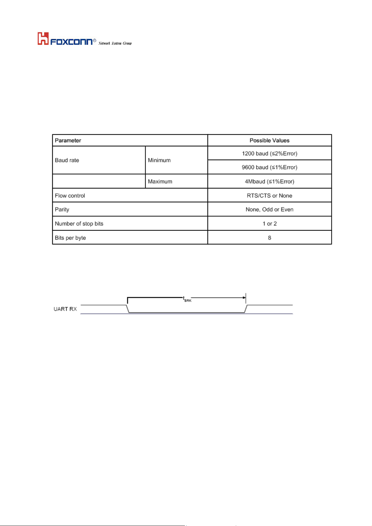
Table 1: Possible UART Settings
The UART interface can reset BlueCore5 Multimedia External on reception of a break signal. A break is
identified by a continuous logic low (0V) on the UART_RX terminal, as shown in Figure2. If tBRK is longer
than the value,defined by the PS Key PSKEY_HOSTIO_UART_RESET_TIMEOUT, (0x1a4), a reset occurs.
This feature allows a host to initialise the system to a known state. Also, BlueCore5 Multimedia External can
emit a break character that may be used to wake the host.
Figure 2: Break Signal
Note:
The DFU boot loader must be loaded into the Flash device before the UART or USB interfaces can be used.
This initial flash programming can be done via the SPI.
Federal Communication Commission Interference Statement
This equipment has been tested and found to comply with the limits for a Class B digital device, pursuant to Part 15 of the
FCC Rules. These limits are designed to provide reasonable protection against harmful interference in a residential
installation. This equipment generates, uses and can radiate radio frequency energy and, if not installed and used in
accordance with the instructions, may cause harmful interference to radio communications. However, there is no
guarantee that interference will not occur in a particular installation. If this equipment does cause harmful interference to
radio or television reception, which can be determined by turning the equipment off and on, the user is encouraged to try to
correct the interference by one of the following measures:
- Reorient or relocate the receiving antenna.
- Increase the separation between the equipment and receiver.
- Connect the equipment into an outlet on a circuit different from that
to which the receiver is connected.
- Consult the dealer or an experienced radio/TV technician for help.
This device complies with Part 15 of the FCC Rules. Operation is subject to the following two conditions: (1) This device
may not cause harmful interference, and (2) this device must accept any interference received, including interference that
may cause undesired operation.
Page 5

FCC Caution: Any changes or modifications not expressly approved by the party responsible for compliance could void the
This device is intended only for OEM integrators under the following conditions:
The transmitter module may not be co-located with any other transmitter or antenna,
As long as the condition above is met, further transmitter test will not be required. However, the OEM integrator is still
responsible for testing their end-product for any additional compliance requirements required with this module installed
(for example, digital device emissions, PC peripheral requirements, etc.).
IMPORTANT NOTE: In the event that the condition can not be met (for example certain laptop configurations or
co-location with another transmitter), then the FCC authorization is no longer considered valid and the FCC ID can not be
used on the final product. In these circumstances, the OEM integrator will be responsible for re-evaluating the end product
(including the transmitter) and obtaining a separate FCC authorization.
The final end product must be labeled in a visible area with the following: “Contains FCC ID: VIL-43XXT”.
The OEM integrator has to be aware not to provide information to the end user regarding how to install or remove this RF
module in the user’s manual of the end product which integrates this module.
The end user manual shall include all required regulatory information/warning as show in this manual.
user's authority to operate this equipment.
End Product Labeling
Manual Information To the End User
Industry Canada Statement
This device complies with RSS-210 of the Industry Canada Rules. Operation is subject to the following two conditions:
1) this device may not cause interference and
2) this device must accept any interference, including interference that may cause undesired operation of the device
IC Radiation Exposure Statement:
This equipment complies with IC radiation exposure limits set forth for an uncontrolled environment. End users
must follow the specific operating instructions for satisfying RF exposure compliance. To maintain compliance
with IC RF exposure compliance requirements, please follow operation instruction as documented in this
manual.
This device is intended only for OEM integrators
under the following conditions:
The transmitter module may not be co-located with any other transmitter or antenna.
As long as conduction above is met, further transmitter test will not be required. However, the OEM integrator is still
responsible for testing their end-product for any additional compliance requirements required with this module
installed (for example, digital device emissions, PC peripheral requirements, etc.).
IMPORTANT NOTE: In the event that these conditions can not be met (for example certain laptop configurations
or co-location with another transmitter), then the IC authorization is no longer considered valid and the IC ID can not
be used on the final product. In these circumstances, the OEM integrator will be responsible for re-evaluating the end
product (including the transmitter) and obtaining a separate IC authorization.
End Product Labeling
The final end product must be labeled in a visible area with the following: “Contains TX IC : 6765A-43XXT”.
Manual Information That Must be Included
The OEM integrator has to be aware not to provide information to the end user regarding how to install or remove.
This RF module in the user’s manual of the end product which integrates this module.
The user’s manual for OEM Integrators must include the following information in a prominent location
“IMPORTANT NOTE: To comply with FCC RF exposure compliance requirements. The antenna must not be
co-located or operating in conjunction with any other antenna or transmitter”.
 Loading...