

Page 1
Page 2
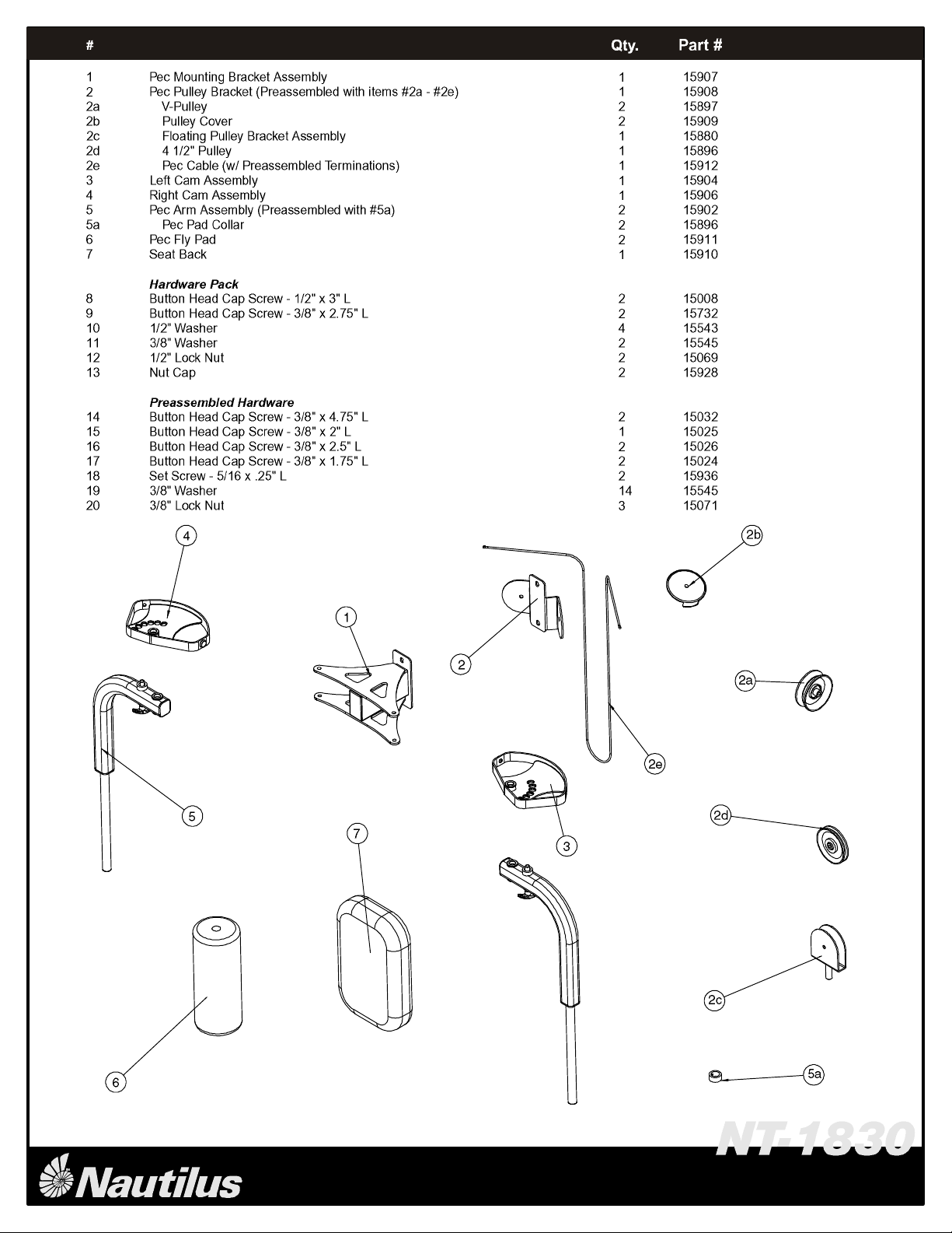
Complete Components List
o
o
o
o
o
o
o
o
o
o
o
o
o
o
o
o
o
o
o
o
o
o
o
o
o
o
s
s
s
s
s
s
1
Page 3
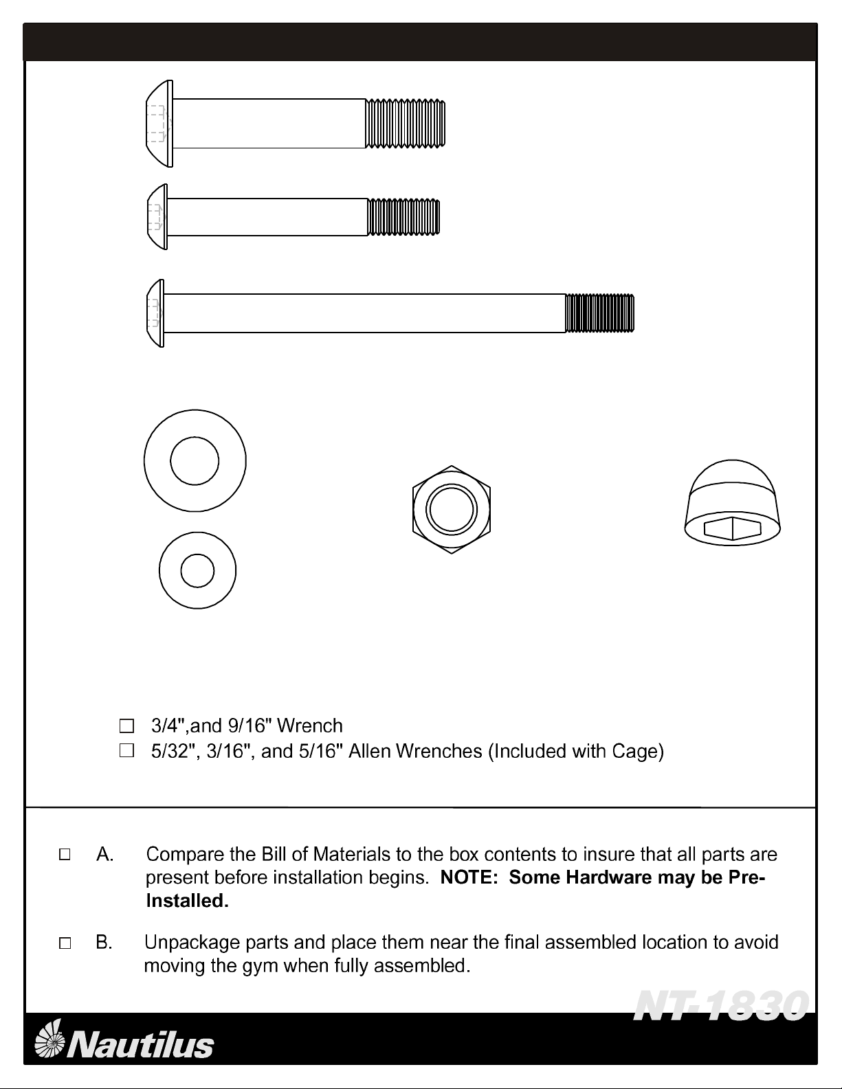
#8
Qty: 2
#9
Qty: 2
#14
Qty: 2
Hardware Size Chart
#10
Qty: 4
#11
Qty: 2
Qty: 2
Required Tools:
#12
#13
Qty: 2
2
Page 4

step
1
Step #1 Materials:
3
Page 5

step
2
Step #2 Materials:
4
Page 6

step
D
C
G
B
F
E
9
11
F
7
3
A
6
5a
18
Step #3 Materials:
Slide the PEC FLY PAD (6) onto the Right Pec Arm Assembly
A.
(A) and secure with a PEC PAD COLLAR (5a) and a 5/16"
#
5a
11
18
Pec Pad Collar
6
Pec Fly Pad
7
Seat Back
9
Cap Screw - 3/8" x 2.75"L
3/8" Washer
5/16" Set Screw (Preassembled)
Description
Qty.
2
2
1
2
2
2
SET SCREW (18). Tighten all hardware.
Repeat step A for the Left Pec Arm Assembly.
B.
Remove the Lat Cable (G) from the Lat Cable Termination
C.
Assembly (B). Remove the Lat Cable Termination Assembly
(B) from the Lat Upright Assembly (F) and all hardware
(C, D, and E). Discard the Lat Cable Termination Assembly
(B) and all hardware (C, D, and E)
Attach the SEAT BACK (7) to the Lat Upright Assembly (F)
D.
with the hardware shown. Tighten all Hardware.
TM
5
NT-1830
Page 7

step
B
C
D
E
I
H
2c
2e
G
F
4
J
#
2c
2e
Cable Termination Detail
Step #4 Materials:
Floating Pulley Bracket Assembly
Pec Cable (w/ Terminations)
Description
Qty.
1
1
A
A.
Thread the Lat Cable (A) into the FLOATING PULLEY
BRACKET ASSEMBLY (2c)
Remove the cable termination from both ends of the PEC
B.
CABLE (2e) by removing the Button Head Cap Screw (B),
Spacer (C), U-Bracket (D), 2 - Washers (J), and Nut (E).
Attach the PEC CABLE (2e) to the Left Cam Assembly (F)
C.
using the given hardware.
Attach the other end of the PEC CABLE (2e) to the Right
D.
Cam (I) using the termination on the PEC CABLE (2e).
TM
6
NT-1830
Page 8

Lubrication and Final Check
The NT-1830 is rated to 300lbs (not included users weight).
Maximum user weight limit is 350lbs.
A.
Lubricate Guide Rods using a silicon based lubricant.
B.
Carefully inspect all cables and insure that they are properly seated on the
pulleys and that they pass between the cable stops and pulleys.
C.
Double check all hardware and make sure everything is tightened properly.
Cable Tensioning
A.
Tighten the Cable System using the combination of four adjustment locations.
These locations are the Double Floating Pulley Brackets and the
Selector Rod Top Plate Assembly. The Cable System should be tightened
as tight as possible yet still allow the Selector Pin to freely engage
all weights.
B.
After the cables are tensioned load the gym with as high a weight as you feel
comfortable with and pull each cable several times to set and stretch the cables.
C.
After the cables are set and stretched, the Cable System may need to be re tensioned. Tension the cables as described in Step A.
D.
The cables may need to be tensioned periodically as they may stretch slightly
over time.
E. INSPECT THE CABLES MONTHLY! Replace immediately if cables show any
signs of damage including cracking, splitting, fraying or bulging.
The assembly of your NT-1830 is now complete.
Should you have any questions or comments regarding your Nautilus
product, please feel free to contact our Customer Service Department.
TM
The Nautilus Group
1886 Prairie Way
Louisville, CO 80027
1-800-864-1270
www.nautilus.com
 Loading...