

Page 1
OWNER’S MANUAL and
INSTALLATION INSTRUCTIONS
NP-L8507
Page 2

Freedom Rack Owner’s Manual
Copyright 2016. Core Health and Fitness, LLC. All rights reserved, including those to reproduce this book or parts thereof
in any form without first obtaining written permission from Core Health and Fitness, LLC.
Every effort has been made to keep this information current; however, periodically, changes are made to the information
herein, and these changes will be incorporated into new editions of this publication. All product names and logos are
trademarks of their respective owners.
MANUFACTURER
4400 NE 77th Avenue, Suite 300, Vancouver, WA 98662 USA
Tel +1 (888) 678-2476
www.corehandf.com
CUSTOMER SUPPORT
Contact your local distributor, or Core Health and Fitness, LLC directly at:
Tel +1-800-503-1221
www.support@corehandf.com
Page 3

TABLE OF CONTENTS
• SAFETY INSTRUCTIONS / WARNINGS
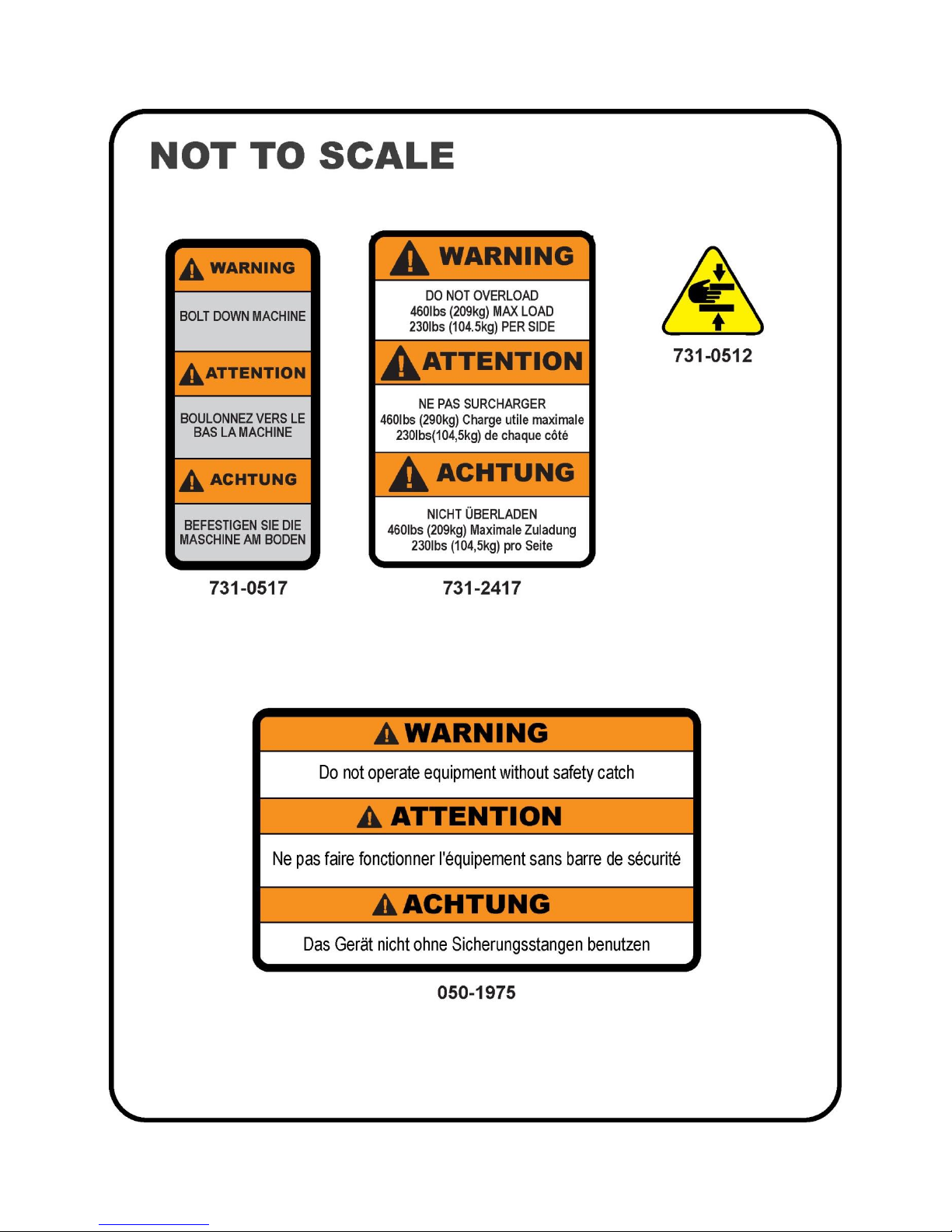
• WARNING LABLES WITH PART NUMBERS
• EXERCISE GUIDELINES
• MAINTENANCE AND SERVICE
• INSTALLATION INSTRUCTIONS
• HARDWARE
1
4
5
6
7
20
Page 4

Inspiration safety and warning information
It is very important that you read and review this manual before operating the Product and keep this manual for
future reference. Remember to perform the periodic maintenance requirements specified in the Manual to
assure proper operation and your continued satisfaction.
It is the sole responsibility of the purchaser of Nautilus® Freedom Rack® to read the owner’s manual, warning labels and
instruct all individuals, whether they are the end user or supervising personnel on proper usage of the equipment.
It is recommended that all users of the Nautilus Freedom Rack be informed of the following information prior to its use.
Nautilus recommends that all commercial fitness equipment be used in a supervised area. It is recommended that the
equipment be located in an access controlled area. Control is the responsibility of the facility owner. The extent of control
is at the discretion of the owner.
Proper Usage
Do not use any equipment in any way other than designed or intended by the manufacturer. It is imperative that the rack
is properly to avoid injury.
Keep hands and feet clear at all times from moving parts to avoid injury.
Read all machine warnings and seek the instruction of a qualified fitness professional prior to using any Nautilus strength
product.
Anchoring Equipment
All equipment MUST be secured (bolted and tightened) to a solid, level surface, using a minimum of 3 of the anchoring
holes provided, to stabilize and eliminate rocking or tipping over. Shim any mounting surface that does not rest thoroughly
on the floor using flat washers, DO NOT force the foot to contact the ground with anchors.
Fasteners must have a minimum of 500 lbs. tensile capacity, be a bolt of grade 2 or better and be installed per the bolt
manufacturer’s specifications.
WARNING: Due to the wide variety of flooring on which equipment may be anchored or installed and differences in
applicable local building codes, Core Health & Fitness is not responsible for any damage to the flooring that may result
due to anchoring or installing equipment to the floor and for compliance with local building codes. Only licensed
contractors or certified installers should be used to insure proper anchoring, installation, and compliance with local
building code.
•Page 1
Page 5

Check for damaged parts
DO NOT use any equipment that is damaged and or has worn or broken parts. Use only replacement parts supplied by
Nautilus® and Core Health & Fitness.
MAINTAIN LABELS AND NAMEPLATES: Do not remove labels for any reason. They contain important information. If
unreadable or missing, contact Nautilus for a replacement.
MAINTAIN ALL EQUIPMENT: Preventative maintenance is the key to smooth operating equipment as well as keeping
the product in safe operating condition. Failure to conduct preventative maintenance by the owner may cause the
product to operate in an unsafe manner. Equipment needs to be inspected and maintained at regular intervals per the
preventative maintenance schedule provided in this manual.
Ensure that any person(s) making adjustments or performing maintenance or repair of any kind is qualified to do so.
Nautilus will provide service and maintenance training at our corporate facility upon request or in the field if proper
arrangements are made.
Safety and warning information
Specific operating warnings
1. This equipment is designed for use in a commercial gymnasium or health club. To ensure the proper use of the
equipment in a safe manner, all users of the equipment should read this manual before using the machine. This
machine should be made a part of your club training program in order that the equipment is used by your members
in a safe manner as intended. In addition to instructing the club members in the proper use of the equipment, the
club member should obtain a complete physical examination form their health care provider before beginning any
exercise program.
2. This machine is not intended to be used by children. It is not intended to be used by persons with reduced physical,
sensory, or mental capabilities or lack of experience and knowledge, unless given instruction and under the personal
supervision concerning use of the machine by a person responsible for their safety. Do not leave children
unsupervised around the machine.
3. Do not over exert yourself during exercise. Stop exercising if you feel pain or tightness in your chest, become short
of breath or feel faint. If you feel pain or experience any abnormal symptoms, stop exercising and consult your
health care provider.
4. The safety and integrity of this machine can only be maintained when the equipment is regularly examined for
damage and wear and repaired. It is the sole responsibility of the owner of this equipment to ensure that regular
maintenance is performed. Worn or damaged parts must be replaced immediately or the equipment removed from
service until the repair is made.
5. DO NOT attempt to fix a broken or jammed machine. Contact appropriate staff or Nautilus Service.
6. Ensure all adjustment and locking features are properly secured before using the equipment.
7. Load plates evenly and carefully to avoid tipping equipment and possible crushing injuries. DO NOT exceed
maximum load of 500 lbs. (227.3 kgs) DO NOT exceed 230 lbs. (104.5 kgs) per side of loaded weight
8. ALWAYS USE safety stops as directed DO NOT use if guards are missing or damaged.
•Page 2
Page 6

9. ALWAYS position safety stops as outlined on the user placard descriptions for each movement.
10. Make sure there is enough room for safe access and operation of the NAUTILUS equipment.
11. Make sure that all users are properly trained on how to use the NAUTILUS equipment.
12. USE A SPOTTER when for all activities.
13. Wear proper exercise clothing and athletic shoes during a workout. Avoid wearing loose clothing. Tie back long hair
and keep towels away from the moving parts. Face forward at all times and never attempt to turn around while the
machine is moving.
14. It is the purchaser’s sole responsibility to properly instruct its end users and supervising personnel as to the proper
operating procedures of all Nautilus equipment.
15. Stay clear of any components while in a dynamic state of motion. Keep hands and feet away from all moving parts.
The convergence of these components can cause serious injury.
16. Ensure that any person (s) making adjustments or performing maintenance or repair of any kind is qualified to do so.
17. Routinely inspect all fasteners that join attachments and framework tighten as needed to maintain the integrity of the
unit.
18. Perform regular maintenance checks on the NAUTILUS equipment. Also, pay close attention to all areas most
susceptible to wear.
19. Keep a repair log of all maintenance activities.
20. Immediately replace worn or damaged components. If unable to immediately replace worn or damaged components
then remove the NAUTILUS piece of equipment from service until the repair is made.
21. Use only replacement components supplied by Nautilus. Substitutes are forbidden and will void all warranties.
•Page 3
Page 7
Page 4
Page 8

Exercise Guidelines
• Like most exercise, strength training involves an element of risk. Utilize this information to
assist you and/or your members in making the experience on NAUTILUS both productive and
safe.
• Prior to engaging in any strength-training program, individuals with known health conditions
and/or individuals whom are unfamiliar with the risk (s) involved with weight training, should
first consult with a physician.
• All training sessions should be supervised by trained personnel.
• Be certain that the warning stickers affixed on NAUTILUS, remain on the product and unaltered.
Also, be certain that all the stickers (safety, instructional and/or other) are read and understood
by each user.
• All users should be instructed on the proper use of NAUTILUS as well as those actions that
should be avoided.
• The NAUTILUS Freedom Rack has safety catches specifically designed to enhance the use of
the product and protect the user – ALWAYS use the safety catches as outlined on the user
placards.
In an attempt to minimize user and/or bystander injury:
• Do not lean against framework, plate holders or any component whether it is dynamic or static.
• Stay clear of any components while in a dynamic state of motion. Keep hands and feet away
from all moving parts. The convergence of these components can cause serious injury.
• Exercising on free weight and selectorized products should be performed with the assistance of
a spotter.
• Always insure proper positioning of the safety stops during each exercise set.
Page 5
Page 9

MAINTENANCE AND SERVICE
The Freedom Rack requires very little upkeep to keep your Freedom Rack performing at its best,
the following guidelines are suggested.
GENERAL CLEANING
Wipe the Freedom Rack with a light all-purpose cleaner, such as diluted Simple Green at
a 30:1 solution.
Dry the Freedom Rack with a soft cloth to prevent rust.
To prevent rust build up it is advised to wipe the Freedom Rack with a soft cloth and
some LPS-1 rust preventative.
Do not clean the guide rods or bearings as this will cause failure of the bearings.
LUBRICATION OF GUIDE RODES
Place light oil (i.e. Three-In-One) onto a clean rag and wipe it along the vertical and
horizontal steel rods monthly.
The bearings inside the barbell housings are sealed and require no maintenance.
Do not use grease or heavy lubricating oil.
Page 6
Page 10

INSTALLATION INSTRUCTIONS
REQUIRED TOOLS:
•• • • • • •• • • • • • • • • • • •
• • • • • • • • • • •• • • • • • • • •
2 • 13mm Box / Open-End Wrenches
GENERAL NOTES:
• Unless otherwise noted Loctite 242/243 or equivalent thread locker must be used on all threaded fasteners. (Do not use
thread locker when a Nyloc nut is used.)
• All Nautilus Strength equipment MUST be secured to the floor using either 10mm or 3/8in. (grade 5 minimum) bolts. To
accommodate this there are four mounting points inside the weight stack and one in either of the small feet.
• This Installation Instructions Manual must be used in conjunction with the equipment’s Owner’s Manual. The Owner’s
manual describes equipment setup and instructs members on how to use it correctly and safely.
• The Freedom Rack requires at least two people to perform the installation.
THREAD LOCKER APPLICATION: Clean all threads and holes, apply no more than 3-4 drops per bolt.
2 • 17mm Box / Open-End Wrenches
Thru Holes Blind Holes
Metric Steel Bolts Torque Specifications
Bolt Size Thread Pitch Torque, N-m (lbs-ft)
6mm 1.25 10 to13.5 (8 to10)
8mm 1.25 25.5 to 28.5 (19 to 21)
10mm 1.75 55.5 to 58 (41 to 43)
12mm 1.25 61 to 65 (45 to 48)
• Torque all hardware to values as specified above, unless noted otherwise.
• See Page 11 of this manual for fastener sizing information; for reference only.
• Note: All torque values are in N-m unless otherwise stated.
Should any component not be present or if you have any operational questions, please refer to your owner’s manual or on the
web @ www.startrac.com . Specifically refer to your Inspiration serial number and model number labeled on your equipment.
PACKAGING REMOVAL:
Carefully remove all packaging materials that wrap the equipment. DO NOT USE A KNIFE OR BOX
CUTTER AS YOU MAY DAMAGE THE EQUIPMENT. At this time remove any sub-components from
the pallet and set aside for later assembly.
Page 7
Page 11

UNPACK THE MAX RACK and ASSEMBLE UPPER WELDMENTS:
NOTE: TAKE CARE WHILE OPENING THE BOXES. KEEP TRACK OF ALL ITEMS YOU REMOVE FROM
THE BOXES. TAKE CARE NOT TO LAY ITEMS ON SURFACES THAT MAY SCRATCH THE
PRODUCT.
1. Take the front and back upper weldments and place them on a soft surface. (A moving blanket will
help reduce damage from hard surfaces)
2. Take (2) of the cross weldment and lay them between the upper weldments.
3. Take (4) bracket and lay (2) at each end as shown below.
4. You will need (8) m10 x 140mm Hex Head bolts (PN:731-2398), (8) m10 Nyloc nuts (PN:731-2420),
and (16) m10 washers (PN:731-2419). NOTE: Make sure you use the right length of bolt.
5. Using (2) 17MM box wrenches assemble the components as seen below. Snug the fasteners at this
time.
Page 11
Page 12

ASSEMBLE UPRIGHTS:
1. Take the (4) uprights and slide the onto the correct post sleeve. See images below. Note: the (2)
fixed feet go onto the sleeved weldment with the handle grips. The adjustable feet go in the back. All
mounting holes are to the outside of the user area.
2. Take (20) m10 washers (PN:731-2419) and (20) m10 x 25 Hex Head bolts (PN:731-2333). NOTE:
Remember to use thread locker.
3. Using a 17mm box wrench install and tighten all (20) fasteners as shown below.
Fixed
Adjustable
Fixed
Adjustable
Page 12
Page 13

UPRIGHT MAIN ASSEMBLY:
NOTE: due to the weight of the assembly, you should always have at least 2 people when moving these
assemblies.
1. Lay assembly on its side. Support legs as you rotate assembly. Note: take special care not to drop
the assembly.
2. Lift top of assembly to upright the Main frame.
MOVE MAIN ASSEMBLY:
1. Move assembly to the position where it will be used, remember to leave room behind for the rest of
the assembly. NOTE: Make sure you leave enough space to allow a safe and clear workout area.
2. Install (4) boots (PN:731-0021) under the feet.
Page 13
Page 14

INSTALL WEIGHT HOLDERS:
1. Take the (2) weight holder weldments (PN:731-2355-XX) from the packaging.
2. Using (2) mounting plate (PN:731-23), (4) m10 x 140 Hex Head Bolts (PN:731-2398), (8) m10
Washers (PN:731-2419), and (4) m10 Nyloc Nuts (PN:731-2420), install the weldment to the back of
the Main Assembly. Before tightening Fasteners place (2) boots (PN:731-0021) under the feet of the
weldments. Use (2) 17mm box wrenches to lightly tighten these fasteners at this time. NOTE: Make
sure you use the right length of bolt.
INSTALL LOWER BRACES:
1. Take the (2) cross brace weldments (PN:731-2317-XX) from the packaging.
2. Using (2) brackets (PN:731-2315-XX), (8) m10 x 140 Hex Head Bolts (PN:731-2398), (16) m10
Washers (PN:731-2419), and (8) m10 Nyloc Nuts (PN:731-2420) install the weldments between the
legs of the Main Assembly. Adjust all six feet to firm to the ground. Use (2) 17mm box wrenches
tighten all fasteners at this time even upper cross members. NOTE: Make sure you use the right
length of bolt.
Page 14
Page 15

INSTALL BACK BRACE:
1. Take the Back Cross Brace (PN:731-2379-XX) from the packaging.
2. Using (2) mounting plate (PN:731-2379-XX), (8) m10 x 80 Hex Head Bolts (PN:731-2400), (16) m10
Washers (PN:731-2419), and (8) m10 Nyloc Nuts (PN:731-2420), install the weldment between the
two weight holders. Use (2) 17mm box wrenches to tighten these fasteners at this time.
INSTALL BAR HOLDERS:
1. Take the (4) Bar Holders (PN:731-2331) from the packaging.
2. Using (12) m10 x 135 Hex Head Bolts (PN:731-2334), (12) m10 Washers (PN:731-2419), (12) M10
Large Washers (PN:731-2346), and (12) m10 Nyloc Nuts (PN:731-2420), install the weldments to the
upright legs. Take note of the Workout Placards, make use they are facing the inside of the unit. Look
at the bottom of each placard for the number and use the image below for placement on the unit. Use
(2) 17mm box wrenches to tighten these fasteners at this time. NOTE: Make sure you use the
right length of bolt.
Page 15
Page 16

INSTALL UPPER GUIDE RODS:
1. Take (2) Ø25mm Guide Rods (PN:731-2392) and the Upper Bearing Weldment (PN:731-2349-XX)
from the packaging.
2. You will use (4) Spacer rings (PN:731-2395), (4) m10 x 25 Hex Head Bolts (PN:731-2333), and (4)
m10 Large Washers (PN:731-2396), to install the Guide Rods into the upper mounts. Use a 17mm
box wrench to install one bolt washer and space into one end of each rod. Slide the rods through the
front mounts taking care not to scratch rods. With the rods through the first mounts now slide the
Bearing Weldment (PN:731-2349-XX) over the rods (the larger hole at the ends of the weldment
should be facing down), NOTE: DO NOT force the bearing onto the rods this may damage the
bearings. Once the Bearing Weldment is on both rods, slide the rods through the back mounts.
3. Take 2 spacers, washers, and bolts, install them on the other end of the Guide rods. Using (2) 17mm
box wrenches tighten the fasteners.
INSTALL BEARING MOUNTS TO BAR:
1. Take the (2) Bearing Mounts (PN:731-2385-XX) from the packaging.
2. Using (4) m10 x 35 Hex Head Bolts (PN:731-2399), (8) m10 Washers (PN:731-2419), and (4) m10
Nyloc Nuts (PN:731-2420), install the weldments to the bar. NOTE: the weldments install to the
outside of the bar flange
Page 16
Page 17

INSTALL SAFETY STOPS:
1. Take the (2) Safety Stops (PN:731-2337) from the packaging.
2. Install the Safety Stops onto the machine at this time, make sure they are both at the same level.
3. Take the Bar with the Bearing guides and place it on the safety stop as in the image.
INSTALL BEARING MOUNTS TO BAR:
1. Take the (2) Ø30mm Guide rods with threaded hole in one end (PN:731-2393) from the packaging.
2. Using (2) m10 x 25 Hex Head Bolts (PN:731-2333), and (2) m10 Large Washers (PN:731-2396),
install the rods through the bar bearing guides with the threaded holes up and the bearing tube to the
back of the machine, then push the rod up into the upper bearing weldment. NOTE: DO NOT force
the rod into the bearing this may damage the bearings.
3. Use a 17mm box wrench to tighten the bolts.
Page 17
Page 18

INSTALL THE LOWER GUIDE RODS:
1. Take the (2) Ø30mm Guide Rods with threaded holes at both ends (PN:731-2391), (2) Round Rubber
Bumpers (PN:731-2394), and (2) “T” shaped Bearing Tubes (PN:731-2390) from the packaging.
2. You will use (4) Spacer rings (PN:731-2397), (4) m10 x 25 Hex Head Bolts (PN:731-2333), and (4)
m10 Large Washers (PN:731-2396), to install the Guide Rods into the lower mounts. Use a 17mm
box wrench to install one bolt, washer and spacer onto one end of each rod. Slide the rods through
the front mounts taking care not to scratch rods.
3. Take one of the “T” shaped Bearing Weldments, and one of the Rubber Bumpers and slide them over
the end of one of the vertical rods (See Below). Now slide the horizontal Guide Rod through the
bearings of the “T” shaped Bearing Tube. NOTE: DO NOT force the bearing onto the rods this may
damage the bearings. Once the Bearing Weldment is on the rods, slide the rod through the back
mount.
4. Take 2 spacers, washers, and bolts, install them on the other end of the Guide rods. Using (2) 16mm
box wrenches tighten the fasteners.
Page 18
Page 19

INSTALL WEIGHT HORNS:
1. Take the (4) Long Weight Horn weldments (PN:731-1454), (4) Short Weight Horn weldments
(PN:731-2297), (12) Weight Horn Covers (PN:731-1376), (12) Base Covers (PN:731-1373), and (12)
End Caps (PN:731-1374) from the packaging.
2. Using (16) M8 x 75mm Hex Head Bolts (PN:731-2356), (32) M8 Washers (PN:731-2421), and (16)
M8 Nyloc Nuts (PN:731-2422) install the weight horns. See image below for placement and order.
Use (2) 13mm box wrenches to tighten fasteners.
3. Once all the weight horns are installed, slide on each side the Base Covers then the Horn Sleeve,
and last the Horn Cap.
4. Once all the caps are installed take the number sticker and apply them to the appropriate cap (see
below). NOTE: the sticker page has both LBS and KG, decide which units you want and then apply
the appropriate stickers.
2.5lbs
or
1.25kg
5lbs or
2.5kg
10lbs
or
5kg
25lbs
or
10kg
35lbs
or
15kg
45lbs
or
20kg
Page 19
Page 20

Page 20
Page 21

FINAL ASSEMBLE CHECK SHEET
1. Make sure ALL fasteners are tightened to specifications is this
manual.
2. See Maintenance and Service page.
1. Perform all steps
MACHINE CLEARANCE AND SPACING
For the safe operation of Freedom Rack® Nautilus recommends that a clearance of 24 inches (60.96cm)
be maintained between and behind machines including moving arms and levers. To insure safe entry
and exit to each unit a walkway of at least 36 inches (91.44cm) inches is recommended front of, or on
the entry side of each machine.
Before using this product, it is essential to read the ENTIRE operations manual and ALL
installation Instructions. The Owner’s manual describes equipment setup and instructs
members on how to use it correctly and safely.
Health related injuries may result from incorrect or excessive use of exercise equipment.
Nautilus strongly recommends you to encourage you and your members to discuss their
health program or fitness regimen with a health care professional, especially if you or they
have not exercised for several years, are over 35, or have known health conditions.
WARNING!
Page 21
Page 22

Page 22
Page 23

Page 23
Page 24

4400 NE 77th Avenue, Suite 300, Vancouver, WA 98662 USA
Contact your local distributor, or Core Health & Fitness directly at:
MANUFACTURER
Tel +1 (888) 678-2476
www.corehandf.com
CUSTOMER SUPPORT
Tel +1-800-503-1221
www.support@corehandf.com
Part Number: 620-8364, Rev A, MAR 2016
 Loading...