

Page 1
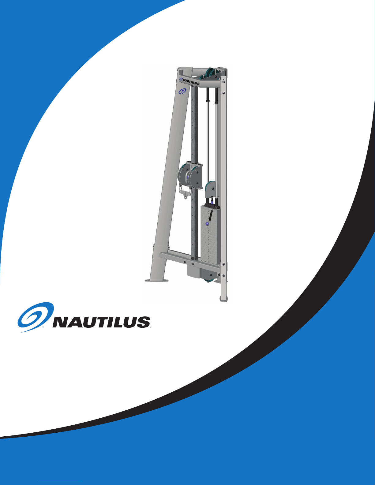
Be Strong.
™
Commercial Free Weights
Adjustable Tower
P/N: 001-40 84 Rev A ( 03/20 /07)
Assembly Manual
Model: F3AT
Page 2

PREFACE/TABLE OF CONTENTS
Thank you for purchasing the Nautilus® Commercial Free Weights Adjustable Tower. For more than 30
years Nautilus® has been producing the world’s finest fitness equipment used in health clubs and homes
around the globe. We hope this product exceeds your expectations and is a valuable tool for your facility.
Please carefully read through this manual to familiarize yourself with the operation of your new Nautilus®
Adjustable Tower. Doing so will help to insure that your users get the most out of your tower, enjoying
safe and effective workouts ahead.
Nautilus, Inc.
World Headquarters
16400 SE Nautilus Drive
Vancouver, Washington, USA 98683
1-800-NAUTILUS
www.nautilus.com
TABLE OF CONTENTS
Safety Precautions/
Product Specifications ..............................3
Before You Assemble .................................
Hardware and Tools ...................................
Box Contents ...............................................
Assembly Guide ..........................................
4
5
6
11
Final Check ...................................................25
Assembly Complete ....................................26
Companion Exercise Equipment
...............27
Limited Warranty .........................................28
Important Contact Numbers .....................29
2
Page 3
SAFETY PRECAUTIONS/PRODUCT SPECIFICATIONS
7 ! 2 . ) . '
7 ! 2 . ) . '
7 ! 2 . ) . '
IMPORTANT SAFETY INSTRUCTIONS
The following definition applies to the word “WARNING” when used in this manual:
Used to call attention to POTENTIAL hazards that could result in personal
injury or loss of life.
READ ALL INSTRUCTIONS BEFORE USING THE MACHINE.
For your safety, perform
all assembly steps in the
sequence given. Improper
assembly can lead to injury.
SAFETY PRECAUTION
Do not lay the machine flat when the weight stack is attached. Permanent damage to the machine will result.
PRODUCT SPECIFICATIONS
User Weight Capacity: 350 lbs / 158.7 kg
Dimensions (assembled):
Shipping Weight: 302.6 lbs / 137.3 kg
46.5”w x 24”l x 92”h / 118.1 cm x 60.9 cm x 233.6 cm
Some components can
be heavy or awkward
to handle. Get help if
necessary.
Net Weight: 286.6 lbs / 130 kg
Power Requirements:
Self Generating
Nautilus® Commercial Free Weights Adjustable Tower Assembly Manual
3
Page 4

BEFORE YOU ASSEMBLE
Note: Throughout this manual, all references to the left or right
side and to the front or back are made as if you were standing on
a level surface and facing the Adjustable Tower.
Basic Assembly Principals
Here are few basic assembly tips that can make assembly of your
Nautilus® Commercial
easy.
1. You can make the assembly process go faster by gathering the
pieces you need for each step prior to starting the step.
Free Weights Adjustable Tower
quick and
2. As a general rule, and for all fasteners on your
Commercial
the right will tighten, turning towards the left will loosen. An
easy way to remember this is by remembering the expression,
“Lefty loosey, righty tighty.”
3. Not all of the tools needed to assemble your Nautilus
Commercial Free Weights Adjustable Tower, are provided.
Refer to the Tool List. You may find the use of a utility knife or
scissors beneficial during the unpacking and assembly process.
4. It is recommended that you use two people to assemble your
Nautilus® Commercial Free Weights Adjustable Tower
Positioning Your Nautilus® Commercial Free Weights
Adjustable Tower
Take great care when moving your Commercial Free Weights
Adjustable Tower into place prior to assembly.
The
Adjustable Tower
safely move from one location to another. Remove weights before
attempting to move the unit.
Free Weights Adjustable Tower
is heavy and requires at least two people to
Nautilus®
, turning toward
®
.
4
Page 5

HARDWARE CARD
6
2
1
8
4
3 11
16
15
12
10
5
7
14
9
13
HARDWARE NOT TO SCALE
HARDWARE AND TOOLS
REF # DESCRIPTION QTY
1 CLIP, CARABINEER 2
2 PLASTIC PLUG 2
3 SCW-BHCS 0500x2 G5-BLKZ 3
4 SCW-BHCS 0500x2.75 G5-BLKZ 3
5 SCW, BHSC 0500x3 G5-BLKZ 4
6 SCW, BHSC 0500x3.25 G5-BLKZ 5
7 SCW, BHSC 0500x6.5 G5-BLKZ 2
8 SCW, BHSC 0500x6.75 G5-BLKZ 6
9 WSH-FLAT 0500 REGULAR BLKZ 40
10 NUT-NL 0500 G-5 BLKZ 21
11 SCREW, BHSC 1/4x.75, TH CUTTING 1
12 SCW-SHCS 0250x1.75 G5-BLKZ
1
13 WRENCH, ALLEN 5/32 1
14 WRENCH, ALLEN 3/16 1
15 WRENCH, ALLEN 7/32 BLK 1
16 WRENCH, ALLEN 5/16 BLK 1
TOOLS
3/4” Wrench or Adjustable Wrench
9/16” Wrench or Adjustable Wrench
NOT
PROVIDED
7/16” Wrench or Adjustable Wrench
5/16” Wrench or Adjustable Wrench
Nautilus® Commercial Free Weights Adjustable Tower Assembly Manual
5
Page 6
6
5
4
8
3
7
2
1
9
10
11
12
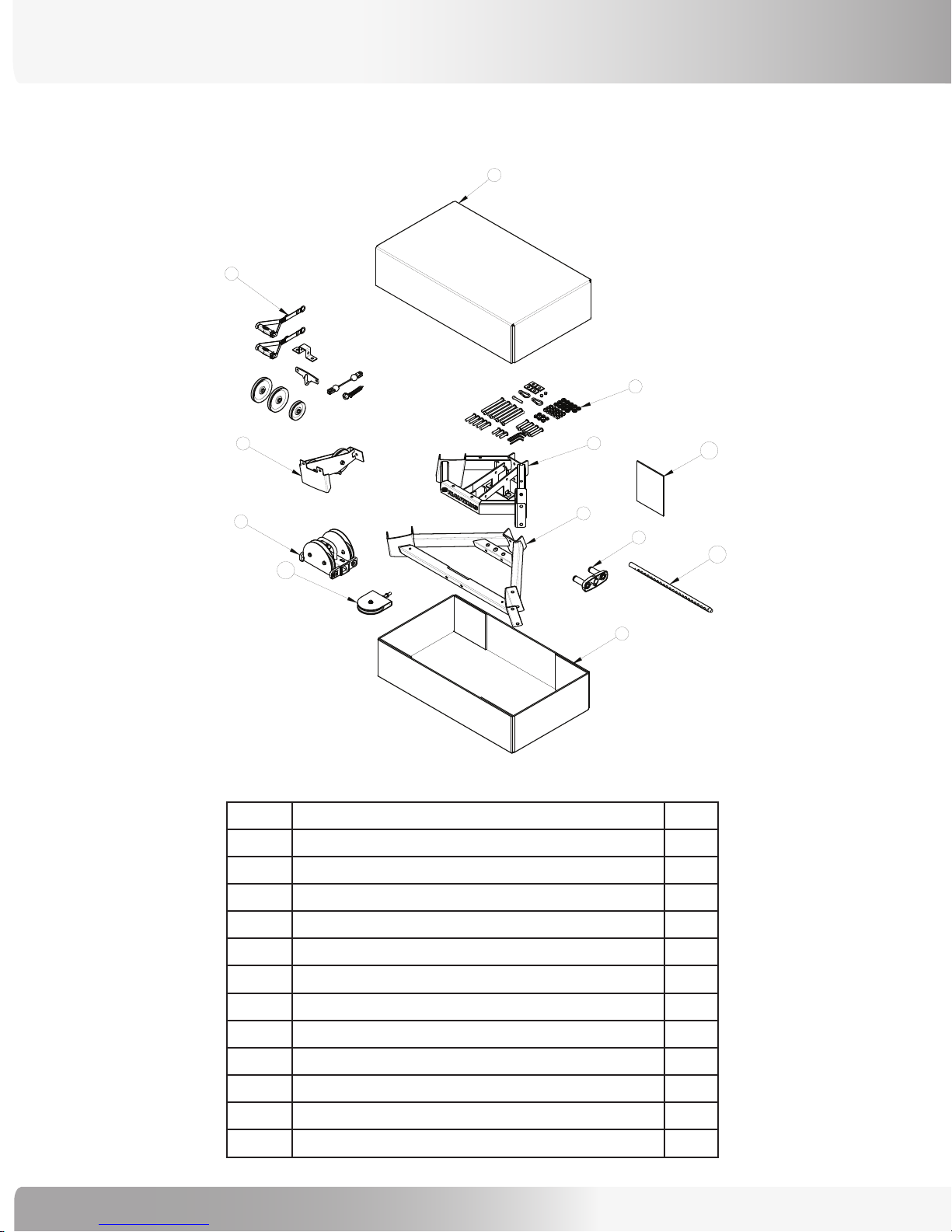
BOX CONTENTS
BOX #1
REF # DESCRIPTION QTY
1 BOX 1, TOP, F3AT 1
2 BOX 1, BOTTOM, F3AT 1
3 ASSY, TOP WEIGHT 1
4 ASSY, LOWER PULLEYS 1
5 WELDMENT, UPPER TRIANGLE 1
7 ASSY, CABLE AND PULLEYS 1
6 ASSY, LOWER TRIANGLE 1
8 ASSY, HARDWARE, F3AT 1
9 ASSY, DUAL ADJUST. PULLEY SYSTEM 1
10 ASSY, STACK PULLEY 1
11 STEM PIN, CFW STACK 1
12 ASSEMBLY MANUAL
6
1
Page 7
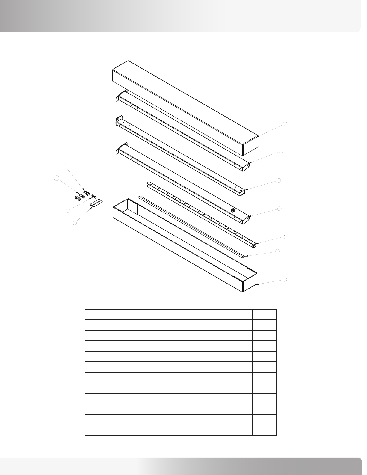
BOX #2
1
6
7
5
4
2
10
11
9
8
3
BOX CONTENTS
REF # DESCRIPTION QTY
1 BOX 2, TOP, F3AT 1
2 BOX 2, BOTTOM, F3AT 1
3 ROD, STACK GUIDE 2
4 TUBE, ADJUSTMENT 1
5 WELDMENT, LEFT UPRIGHT 1
6 WELDMENT, RIGHT UPRIGHT 1
7 WELDMENT, REAR UPRIGHT 1
8 WASHER-FLAT 0750 NARROW BLKZ 2
9 TUBE, GUIDE ROD STOP 2
10 GUIDE ROD BUSHING 2
11 BUMPER, UPPER GUIDE ROD 4
Nautilus® Commercial Free Weights Adjustable Tower Assembly Manual
7
Page 8
BOX CONTENTS
3
2
WRAP PLATES IN
ONE PLASTIC BAG
PRESS BUSHINGS INTO
WEIGHT PLATES PRIOR TO SHIPPING
WEIGHTS, 10 LB.
REF # DESCRIPTION QTY
1 BOX, 10LB PLATES 1
2 WEIGHT PLATE, 10LB, BOTTOM 5
3 STANDARD GUIDE ROD/WEIGHT BUSHING 10
8
Page 9

WEIGHTS, 10 LB.
2
1
1
3
4
PRESS BUSHINGS INTO
WEIGHT PLATES PRIOR TO SHIPPING
WRAP PLATES IN
ONE PLASTIC BAG
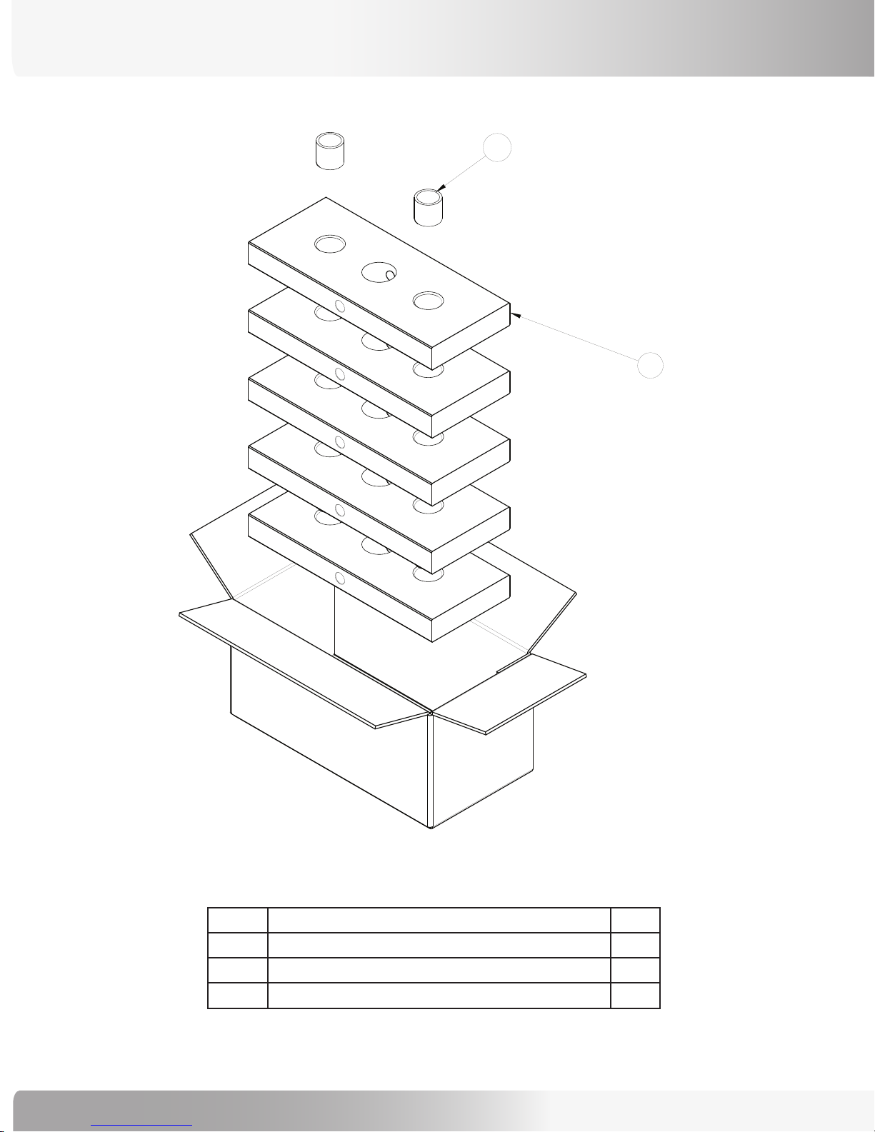
BOX CONTENTS
REF # DESCRIPTION QTY
1 WEIGHT PLATE, 10LB, BOTTOM 2
2 STANDARD GUIDE ROD/WEIGHT BUSHING 6
3 WEIGHT PLATE, 10LB, SECOND 1
4 BOX, 10LB PLATES 1
Nautilus® Commercial Free Weights Adjustable Tower Assembly Manual
9
Page 10

BOX CONTENTS
1
2
4
3
-PLACE DECALS AND INSTRUCTIONS ON TOP
OF SMALLER PACKAGES BEFORE CLOSING
ALL 10 LB. WEIGHTS AND DECALS
REF # DESCRIPTION QTY
1 DECALS, 10LB WEIGHT STACK 1
2 ASSEMBLY, 10LB PLATES, BOX 2 1
3 ASSEMBLY, 10LB PLATES, BOX 1 4
4 BOX, 10LB PLATES, OVERALL 1
10
Page 11

ASSEMBLY GUIDE
The following instructions provide direction in assembling the Tower, Pulleys, Weights, and Cabling for the Nautilus® Commercial
Free Weights Adjustable Tower. All instructions in the manual are given with the orientation of standing on a level surface and
facing the Adjustable Tower.
Step 1: Assemble Triangle and Rear Upright
Weldments
Figure 1:
Locate the following for this step:
Parts:
• Ref 7, Rear Upright Weldment Qty. 1
• Ref 5, Upper Triangle Weldment Qty. 1
• Ref 6, Lower Triangle Weldment Qty. 1
Hardware:
• Ref 6, 1/2”x 3 1/4” Button Head Bolt Qty. 3
• Ref 10, 1/2” Nuts Qty. 3
• Ref 9, 1/2” Washers Qty. 6
Tools:
• Ref 16, 5/16” Allen Wrench
• 3/4” Wrench
Refer to Figure 1:
1-1 With the Rear Upright on is back on a clear floor
area, insert three 3 1/4” bolts.
1-2 Place the Upper and Lower Triangle Weldments
in the proper locations and loosely tighten the
hardware.
Nautilus® Commercial Free Weights Adjustable Tower Assembly Manual
11
Page 12

ASSEMBLY GUIDE
Step 2: Assemble Left and Right Upright Weldments
Figure 2:
Locate the following for this step:
Parts:
• Ref 5, Left Upright Weldment Qty. 1
• Ref 6, Right Upright Weldment Qty. 1
Hardware:
• Ref 7, 1/2”x 6 1/2” Button Head Bolt Qty. 2
• Ref 8, 1/2”x 6 3/4” Button Head Bolt Qty. 6
• Ref 10, 1/2” Nuts Qty. 6
• Ref 9, 1/2” Washers Qty. 14
Tools:
• Ref 16, 5/16” Allen Wrench
• 3/4” Wrench
Refer to Figure 2:
2-1 With the Assembly still on its back, place the Left
and Right Uprights in place and loosely secure
with 6 ½” bolts.
2-2 Lift the Tower to the upright position and
tighten all hardware.
2-3 Be sure the Tower is in its desired location at
this point and that the feet are all sitting level.
12
Page 13

ASSEMBLY GUIDE
GAP MUST BE FROM 0.0MM TO 22.4MM
DURING NORMAL OPERATION TO ALLOW
MINIMUM THREAD ENGAGEMENT.
TOP NUT MUST BE FULLY
TIGHTENED BEFORE
MEASURING GAP
25.4 MINIMUM
THREAD ENGAGEMENT
22.4
25.4
IF GAP EXCEEDS 22.4 MM, REPLACE THE CABLE.
Step 3: Assemble Stack Pulley and Top Weight Plate
Figure 3:
Locate the following for this step:
Parts:
• Ref 10, Stack Pulley Assembly Qty. 1
• Ref 3, Top Weight Plate Assembly Qty. 1
• Ref 11, Stem Pin Qty. 1
Hardware:
• Ref 12, 1/4” x 1 3/4” Socket Head Cap Screw Qty. 1
Tools:
• Ref 14, 3/16” Allen Wrench
Refer to Figures 3 and 4:
3-1 Prepare the Top Weight Assembly by loosely
attaching the Stack Pulley Assembly.
3-2 Attach the Stem Pin.
Figure 4:
3-2 Set aside the Assembly.
Note: When attaching the Weight Stack Pulley, make
sure that there is 25.4 mm (1in.) of thread engagement
(Figure 4). In order to ensure proper thread engagement,
set the bottom nut at the 25.4 mm (1in.) minimum
distance, then thread the Pulley Assembly into the Top
Weight (refer to Step 12 for the procedure to thread the
Pulley Assembly). To check that you have the proper
engagement after the Pulley is installed, measure the
distance between the two nuts when the top nut is fully
tightened. The distance between nuts can not exceed
22.4 (.88 in.) mm.
Nautilus® Commercial Free Weights Adjustable Tower Assembly Manual
13
Page 14

ASSEMBLY GUIDE
Step 4: Install Guide Rods and Bumpers
Figure 5:
Locate the following for this step:
Parts:
• Ref 3, Guide Rod Qty. 2
• Ref 11, Bumper Guide Rod Qty. 2
Hardware:
• None
Tools:
• None
Refer to Figure 5:
4-1 Place the Guide Rods and Bumpers in the Bottom
Triangle Weldment, allowing the Rods to lean
forward.
14
Page 15

Step 5: Install Weight Plates
ASSEMBLY GUIDE
Figure 6:
Locate the following for this step:
Parts:
• 10 lb Weight Plate, CFW Qty. 23
• Top Weight Assembly from Step 3
Hardware:
• None
Tools:
• None
Refer to Figures 6 and 7:
5-1 Locate and set aside the 10 lb Weight with the extra
hole in the front to retain the Weight pin. This is
the “Second Plate” and is the last plate you place
before adding the Top Weight Assembly (Figure 6).
Note: Make sure that the extra hole in the “Second
Plate” is facing to the left (as you face the machine).
Figure 7:
5-2 Carefully slide all the Weight plates onto the Guide
Rods, finishing with the ”Second Plate” and the Top
Weight Assembly (Figure 7).
Nautilus® Commercial Free Weights Adjustable Tower Assembly Manual
15
Page 16

Step 6: Install Guide Rods
ASSEMBLY GUIDE
Figure 8:
Locate the following for this step:
Parts:
• Ref 4, Bumper, Guide Rod Qty. 2
• Ref 9, Tube, Guide Rod Qty. 2
• Ref 10, Guide Rod Bushing Qty. 2
Hardware:
• Ref 9, 1/2” Washers Qty. 2
Tools:
• None
Refer to Figure 8:
6-1 Place the components onto the Guide Rod ends in
the order shown.
Note: Do not lift the Guide Rods into place at this time.
16
Page 17

ASSEMBLY GUIDE
Figure 9:
Step 7: Install Seat Guide Rods into Upper Triangle
Weldment
Locate the following for this step:
Parts:
• None
Hardware:
• Ref 4, 1/2” x 2 3/4” Button Head Bolt Qty. 2
• Ref 11, 1/4” x 3/4” Thread Cutting Screw Qty. 1
• Ref 10, 1/2” Nuts Qty. 2
• Ref 9, 1/2” Washers Qty. 4
Tools:
• Ref 16, 5/16” Allen Wrench
• Ref 13, 5/32” Allen Wrench
• 3/4” Wrench
Refer to Figure 9:
7-1 Tip the Guide Rods to a vertical position. Lift the
Guide Rods one at a time so that the Guide Rod
Bushing is seated completely into the Upper
Triangle Weldment.
7-2 Place the 1/2” x 2 3/4” retaining bolt into the hole
just below the Guide Rod and secure with a 1/2”
nut.
7-3 Repeat 7-1 and 7-2 for both sides.
7-4 Attach the Pin Rope to the Second Plate using the
1/4” x 3/4” Thread Cutting Screw.
7-5 Firmly tighten the hardware.
Nautilus® Commercial Free Weights Adjustable Tower Assembly Manual
17
Page 18

ASSEMBLY GUIDE
Step 8: Adhere Weight Stack Decals
Figure 10:
Locate the following for this step:
Parts:
• 10 lb Weight Plate Decals Qty. 23
Hardware:
• None
Tools:
• None
Refer to Figure 10:
8-1 Prepare the Weight Plates by degreasing with
denatured alcohol and a primer solution.
8-2 From each Decal strip (12 Decals to a strip
column), remove, separately, one side of the
backing.
8-3 Align the backing to the Plates and press gently
against the backing.
8-4 Firmly rub the decals to secure adhesion to the
Weight Plates.
18
Page 19

ASSEMBLY GUIDE
Step 9: Assemble Adjustable Pulley System
Figure 11:
Locate the following for this step:
Parts:
• Ref 4, Tube, Adjustment Qty. 1
• Ref 7, Spacer, Adjustment Tube Qty. 4
• Ref 7, Bracket, Lower Adjustment Tube Qty. 1
• Ref 9, Dual Adjustable Pulley System Qty. 1
Hardware:
• Ref 5, 1/2”x 3” Button Head Bolt Qty. 2
• Ref 4, 1/2”x 2 3/4” Button Head Bolt Qty. 1
• Ref 10, 1/2” Locknuts Qty. 3
• Ref 9, 1/2” Washers Qty. 6
Tools:
• Ref 16, 5/16” Allen Wrench
• 3/4” Wrench
Refer to Figure 11:
9-1 Position the Adjustment Tube so that the numbers
on it face you.
9-2 Place a spacer on the front and back of
the bottom most holes and secure with a 3” bolt.
Firmly tighten the hardware.
9-3 Place the Bracket, Lower Adjustment Tube over
the bottom-most holes on the side of the
Adjustment Tube and secure with a 2 3/4” bolt
(but leave the hardware loose).
9-4 Slide the Dual Adjustment Pulley System
Assembly over the top of the Adjustment Tube
and lock into the #1 location. Note: the Dual
Adjustment Pulley System can be positioned
upside down; upright is when the viewer
window is at the top.
9-5 With the Adjustment Tube numbers facing you,
place a spacer on the front and back of the
top-most holes and secure with a 3” bolt.
Firmly tighten the hardware (except the bottom
bracket bolt).
Nautilus® Commercial Free Weights Adjustable Tower Assembly Manual
19
Page 20

ASSEMBLY GUIDE
Step 10: Install Adjustable Pulley System
Figure 12:
Locate the following for this step:
Parts:
• Assembly from Step 9
Hardware:
• Ref 6, 1/2”x 3 1/4” Button Head Bolt Qty. 1
• Ref 10, 1/2” Locknuts Qty. 1
• Ref 9, 1/2” Washers Qty. 2
Tools:
• Ref 16, 5/16” Allen Wrench
• 3/4” Wrench
Refer to Figure 12:
10-1 Support the Adjustment Assembly with the top most side holes between the mounting bracket in
the Top Weldment Triangle.
10-2 Place and loosely tighten the 3 1/4” bolt.
20
Page 21

ASSEMBLY GUIDE
Step 11: Install Lower Pulley Assembly
Figure 13:
Locate the following for this step:
Parts:
• Ref 4, Lower Pulleys Assembly Qty. 2
Hardware:
• Ref 5, 1/2”x 3” Button Head Bolt Qty. 2
• Ref 6, 1/2”x 3 1/4” Button Head Bolt Qty. 1
• Ref 10, 1/2” Nuts Qty. 3
• Ref 10, 1/2” Locknuts Qty. 2
• Ref 9, 1/2” Washers Qty. 2
Tools:
• Ref 16, 5/16” Allen Wrench
• 3/4” Wrench
Refer to Figure 13:
11-1 Secure the front of the Lower Pulley Assembly
using the two 1/2” x 2 3/4” bolts and the 1/2”
Locknuts.
11-2 Secure the rear of the Lower Pulley Assembly
using the 1/2’ x 3 1/4” bolt and the 1/2” washers
(for rear bolt only; none used on front bolts) and
1/2” nut.
11-3 Firmly tighten all remaining hardware (from this
Step; from Steps 9 and 10, the Top
attaching bolt and lower bracket bolt for the
Tube adjustment).
Nautilus® Commercial Free Weights Adjustable Tower Assembly Manual
21
Page 22

ASSEMBLY GUIDE
Side against the frame
Side facing inward
Step 12: Install Upper Pulley Assemblies
Figure 14:
Locate the following for this step:
Parts:
• Ref 7, 6” Pulley Assembly Qty. 2
• Ref 7, 4 1/2” Pulley Assembly Qty. 1
Hardware:
• Ref 3, 1/2”x 2” Button Head Bolt Qty. 3
• Ref 10, 1/2” Nuts Qty. 3
• Ref 9, 1/2” Washers Qty. 6
Tools:
• Ref 16, 5/16” Allen Wrench
• 3/4” Wrench
Refer to Figures 14 and 15:
12-1 Attach the 6” and 4 1/2” Pulley Assemblies in the
locations shown. Loosely tighten the hardware
until the cable is routed (Figure 14).
Figure 15:
Note: Be sure to orient the 6” Pulleys as shown in
Figure 15.
12-2 Securely tighten the hardware.
22
Page 23

ASSEMBLY GUIDE
Step 13: Thread Cable Through Pulley Assemblies
Figure 16:
Figure 17:
Locate the following for this step:
Parts:
• Ref 7, Assembly, Slotted Strap Forks Qty. 2
• Ref 1, Clip, Carabineer Qty. 2
Hardware:
• None
Tools:
• Ref 15, 7/32” Allen Wrench
• 9/16” Wrench
Refer to Figure 16:
13-1 Attach Cable Ball and Slotted Strap Fork to one
end of the cable. Cable terminations come
attached. Remove one set of the terminations.
Refer to Figures 17, 18, and 19:
13-2 Follow this sequence to install the cable:
a. Start threading the cable into the left side
between the two pulleys of the Adjustable
Dual Pulley system (Figure 17).
b. After you thread the cable through the left
side, direct the cable down in front of the
bottom 4 1/2” pulley.
Note: Make sure to thread the cable between
the groove in the pulley and the thread guide
welded to the frame.
c. Continue threading the cable to the 6”
bottom pulley and up behind it.
Nautilus® Commercial Free Weights Adjustable Tower Assembly Manual
23
Page 24

ASSEMBLY GUIDE
Figure 18:
Step 13: Thread Cable Through Pulley Assemblies,
continued
d. From there, thread the cable all the way up
over the 6” pulley on the right side and back
down in front of the Weight Stack Pulley
Assembly (Figure 18).
e. Thread the cable under the Weight Stack
Pulley Assembly and up behind it.
f. Going up again, thread the cable over
the 6” pulley on the right side of the Tower
and under the 4 1/2” pulley on the Row
Attachment Assembly (Figure 19).
g. Attach the remaining washer, Cable Ball, and
Slotted Strap Fork.
Figure 19:
Note: To align the Weight Stack Pulley, first
make sure that the tension nuts are loose
(assembly should rotate freely) and that all
other steps have been completed.
With the weight pin inserted (amount of
weight is unimportant; simply ensure there is
some weight), pull the cable handles until the
cable is just tight. This should rotate the
pulley to the correct orientation. Tighten the
tension nuts while the cable is tight.
13-3 Tighten the hardware on the Top Pulley
Assemblies.
13-4 Attach remaining accessories (carabineers,
handles).
24
Page 25

Figure 20:
FINAL CHECK
Step 14: Lubrication and Cable Tensioning
Perform this step as the final check.
Refer to Figure 20:
Lubrication
14-1 Lubricate the guide rods using a silicone based
lubricant.
14-2 Carefully inspect all cables and insure that they
are properly seated on the pulleys and that they
pass between the pulleys and cable retainers.
14-3 Make sure all hardware is securely tightened.
Cable Tensioning
14-4 The cables should be as tight as possible while still
allowing the selector pin to freely engage all of
the weights.
14-5 Once the cables are tensioned, load the weight
stack with as much weight as you feel comfortable
with, and pull each cable several times to set and
stretch the cables.
14-6 After the cables are stretched, they may need to
be re-tensioned.
14-7 Over time, the cables may stretch and need to be
re-tensioned.
When cables are properly tensioned, the ball stop
should rest within 1/4” of the Dual Pulley System and
the top weight should sit flush. If the cable is loose
(more than a 1/4” of play), move the bottom tension
nut up the bolt. Next, screw the bolt further down into
the weight stack. If the cable is too tight, unscrew the
bolt from the Weight Stack. Finish by retightening the
bottom tension nut. Make sure to follow the guidelines
above regarding thread engagement.
Nautilus® Commercial Free Weights Adjustable Tower Assembly Manual
25
Page 26

7 ! 2 . ) . '
ASSEMBLY COMPLETE
Step 15: Inspect Assembly
Congratulations!
®
15-1 Assembly of your Nautilus
Weights Adjustable Tower is now complete. Be
sure to fully inspect your Nautilus
Free Weights Adjustable Tower before using it
for the first time.
Commercial Free
®
Commercial
Failure to visually check and
test the assembly before use can
cause damage to the Nautilus®
Commercial Free Weights Smith
Machine Rack and serious injury
to users and bystanders and can
also compromise the effectiveness of your exercise program.
26
Page 27

COMPANION EXERCISE EQUIPMENT
The Nautilus® Racks are designed for use with Nautilus® Free Weights equipment. The Nautilus® Free
Weights line includes the following models:
Utility Benches & Exercise Machines
Commercial Free Weights F3 0-90 Adjustable Utility Bench
•
Commercial Free Weights F3AD Adjustable Decline Utility Bench
•
Commercial Free Weights F3AHE Adjustable Hip Extension
•
Commercial Free Weights F3AAB Adjustable Abdominal Bench
•
Commercial Free Weights F3PC Preacher Curl Bench
•
Commercial Free Weights F3TBR T-Bar Row
•
Commercial Free Weights F3CD Chin Dip Leg Raise
•
Commercial Free Weights F3FU Flat Utility Bench
•
Commercial Free Weights F3SU Seated Utility
•
Olympic Benches & Squat Rack
Commercial Free Weights F3OSB Olympic Supine Bench
•
Commercial Free Weights F3ODB Olympic Decline Bench
•
Commercial Free Weights F3OIB Olympic Incline Bench
•
Commercial Free Weights F3OMB Olympic Military Bench
•
Commercial Free Weights F3SR Squat Rack
•
Towers
Commercial Free Weights F3CC Cable Crossover Tower
•
Commercial Free Weights F3DLATP Dual Pulley Lateral Pulldown Tower
•
Commercial Free Weights F3DROW Row Tower
•
Commercial Free Weights F3AT Adjustable Tower
•
Racks
Commercial Free Weights F3SM Smith Machine
•
Commercial Free Weights F3PR Power Rack
•
Equipment Storage
Commercial Free Weights F3BR Barbell Rack
•
Commercial Free Weights F3 2TDR Two Tier Dumbbell Rack
•
Commercial Free Weights F3 1TDR One Tier Dumbbell Rack
•
Commercial Free Weights F3WT Weight Tree
•
Please contact Nautilus, Inc. or a Nautilus® Representative for information about other products, or go to
www.nautilus.com.
Nautilus® Commercial Free Weights Adjustable Tower Assembly Manual
27
Page 28

LIMITED WARRANTY
Commercial Market Warranty Information
All Nautilus® exercise products are warranted to the
commercial market purchaser to be free from defects in
materials and workmanship. Warranty coverage valid to
the original purchaser only and proof of the purchase will
be required. Any product sold or placed in an application
not recommended by Nautilus will void any warranty
coverage set forth by Nautilus warranty policies and
procedures.
Time Period
15 Years - Frame
3 Years- Mechanical and electrical parts
1 Year- Labor
1 Year - Wear items
What this warranty does not cover
warranty or, at Nautilus’ election, to the replacement
amount of the purchase price of the exercise product
in question. Some states do not permit the exclusion
or limitation of implied warranties or incidental or
consequential damages, so the preceding limitations and
exclusions may not apply to you.
Procedures
Warranty service will in most cases be performed by an
authorized Nautilus Fitness Dealer or Service Technician.
The original purchaser must provide proof of purchase,
Service calls and/or transportation to and from the
Nautilus Dealer is the responsibility of the purchaser.
1. Nautilus will have the option to repair or replace any
exercise product, which requires service.
2. Nautilus will replace any equipment frame that is
structurally defective with a new frame or replace the
unit with a unit of equal value.
1. Users weighing more than 350 lbs.
2. Any damage, failure or loss caused by accident,
misuse, neglect, abuse, improper assembly, improper
maintenance or failure follow instructions or warnings
in this Assembly/Service Manual.
3. Use of product in a manner or environment for which it
was not designed.
Limitations
The foregoing warranties are in lieu of and exclude all
other warranties not expressly set forth herein, whether
expressed or implied by operation of law or otherwise,
including, but not limited to, warranties of merchantability
or fitness for a particular purpose. Nautilus shall in no
event be liable for incidental or consequential losses,
damages or expenses in connection with its exercise
products. Nautilus’ liability hereunder is expressly limited
to the replacement of goods not complying with this
3. Nautilus is not responsible for dealer labor charges for
the component changeovers completed after the labor
related warranty period stated herein.
4. If you elect to repair an exercise product or part
yourself, using the services of someone other than
an authorized Nautilus Fitness Dealer or Service
Technician, or use a replacement part not supplied
by Nautilus, Nautilus shall not be liable for any cost,
damage, failure or loss caused by the use of such
unauthorized service or parts.
28
Page 29

IMPORTANT CONTACT NUMBERS
If you need assistance, please have both the serial number of your machine and the date of purchase available when you
contact the appropriate Nautilus office listed below.
WORLDWIDE CUSTOMER SERVICE
• NORTH AMERICA OFFICE
Nautilus, Inc.
World Headquarters
16400 S.E. Nautilus Drive
Vancouver, Washington, USA 98683
Phone: 800-NAUTILUS (628-8458)
Fax: 800-686-6466
e-mail: cstech@nautilus.com
• NAUTILUS INNOVATION CENTER
Nautilus, Inc.
1886 Prairie Way
Louisville, Colorado, USA 80027
Phone: 800-864-1270
Fax: 800-898-9410
• CORPORATE HEADQUARTERS
Nautilus, Inc.
World Headquarters
16400 S.E. Nautilus Drive
Vancouver, Washington, USA 98683
Phone: 800-NAUTILUS
INTERNATIONAL CUSTOMER SERVICE
• INTERNATIONAL OFFICE
Nautilus International S.A.
Rue Jean Prouvé 6
1762 Givisiez / Switzerland
Tel: +41-26-460-77-77
Fax: +41-26-460-77-70
E-mail: technics@nautilus.com
INTERNATIONAL OFFICES:
• SWITZERLAND OFFICE
Nautilus Switzerland S.A.
Tel: +41-26-460-77-66
Fax: +41-26-460-77-60
• GERMANY and AUSTRIA OFFICE
Nautilus GmbH
Tel: +49 2203 /20 20-0
Fax: +49 2203/20 20-45 45
• ITALY OFFICE
Nautilus Italy s.r.l.
Tel: +39-051-664-6201
Fax: +39-051-664-7461
• UNITED KINGDOM OFFICE
Nautilus UK Ltd.
Tel: +44-1908-267-345
Fax: +44-1908-267-346
• CHINA OFFICE
Nautilus Representative Office
Tel: +86-21-523-707-00
Fax: +86-21-523-707-09
Nautilus® Commercial Free Weights Adjustable Tower Assembly Manual
29
Page 30

For more information about our Commercial Series exercise equipment or other Nautilus®
© 20 07 Nauti lus, Inc. A ll right s reser ved. Naut ilus, th e Nautilu s logo, Naut ilus Ins titut e and Be St rong are ei ther regi stered t rademark s or tradem arks of Nau tilus, I nc.
Naut ilus, Inc. W orld Headq uarter s, 164 00 SE Nau tilus Dri ve, Vancou ver, Washing ton, US A 986 83, 1-8 00- 628 -84 58, ww w.Naut ilus.c om.
Be Strong.
equipment for your home, visit www.Nautilus.com.
™
 Loading...