

Page 1
Be Strong.
™
TreadClimber® Model TC916
Commercial Series
P/N: 001-7013 Rev B (11/09/2006)
Assembly Manual
Page 2

For detailed instructions and inFormation on
7 ! 2 . ) . '
! 4 4 % . 4 ) / .
$ ! . ' % 2
how to use and care For your treadclimber
commercial series exercise machine, model tc916,
reFer to the owner’s manual.
®
2
Page 3

TABLE OF CONTENTS
TREADCLIMBER
®
FEATURES ............................................................................................................................
PRODUCT SPECIFICATIONS .............................................................................................................................. 5
IMPORTANT SAFETY PRECAUTIONS .............................................................................................................. 6
WARRANTY INFORMATION:
TIME PERIOD ......................................................................................................................................... 8
WHAT THIS WARRANTY DOES NOT COVER .................................................................................... 8
LIMITATIONS .......................................................................................................................................... 8
PROCEDURES ......................................................................................................................................... 8
GETTING STARTED:
SELECT YOUR WORKOUT AREA ......................................................................................................... 9
POWER PLUG RECEPTACLE ................................................................................................................ 9
TURNING ON THE POWER .................................................................................................................. 9
UNDERSTANDING THE DISPLAY AND CONTROLS ......................................................................... 9
LIMITED ACCESS CONTROL/MAGNETIC SAFETY STOP ................................................................ 10
MAGNETIC KEY SAFETY STOP ACTIVATION ................................................................................... 10
QUICK START GUIDE ............................................................................................................................. 11
4
MOVING INSTRUCTIONS:
MOVING INSTRUCTIONS FOR FULLY ASSEMBLED UNIT:
MOVING YOUR TREADCLIMBER® TC916 ................................................................................... 12
REMOVING MACHINE FROM PALLET ......................................................................................... 13
MOVING UNIT INTO POSITION IN FACILITY .............................................................................. 14
DISASSEMBLY OF UPRIGHT UNIT:
IMPORTANT INFORMATION TO READ BEFORE DISASSEMBLING UPRIGHT UNIT .. 16
REMOVING REAR STEP ........................................................................................................ 17
REMOVING UPRIGHTS ......................................................................................................... 18
REMOVING BASE PLASTIC ................................................................................................. 19
MOVING TOOL INFORMATION ........................................................................................................... 20
ASSEMBLY INSTRUCTIONS FOR CRATED UNIT:
BEFORE YOU ASSEMBLE
BASIC ASSEMBLY PRINCIPLES ............................................................................................ 22
HARDWARE AND TOOL LIST ............................................................................................................... 23
PARTS LIST REFERENCE GUIDE .......................................................................................................... 24
UNPACKING GUIDE .............................................................................................................................. 26
ASSEMBLY GUIDE ................................................................................................................................. 29
BELT TENSION AND ALIGNMENT ................................................................................................................... 40
IMPORTANT CONTACT NUMBERS: ................................................................................................................. 41
Nautilus® TreadClimber® Model TC916 Assembly Manual
3
Page 4
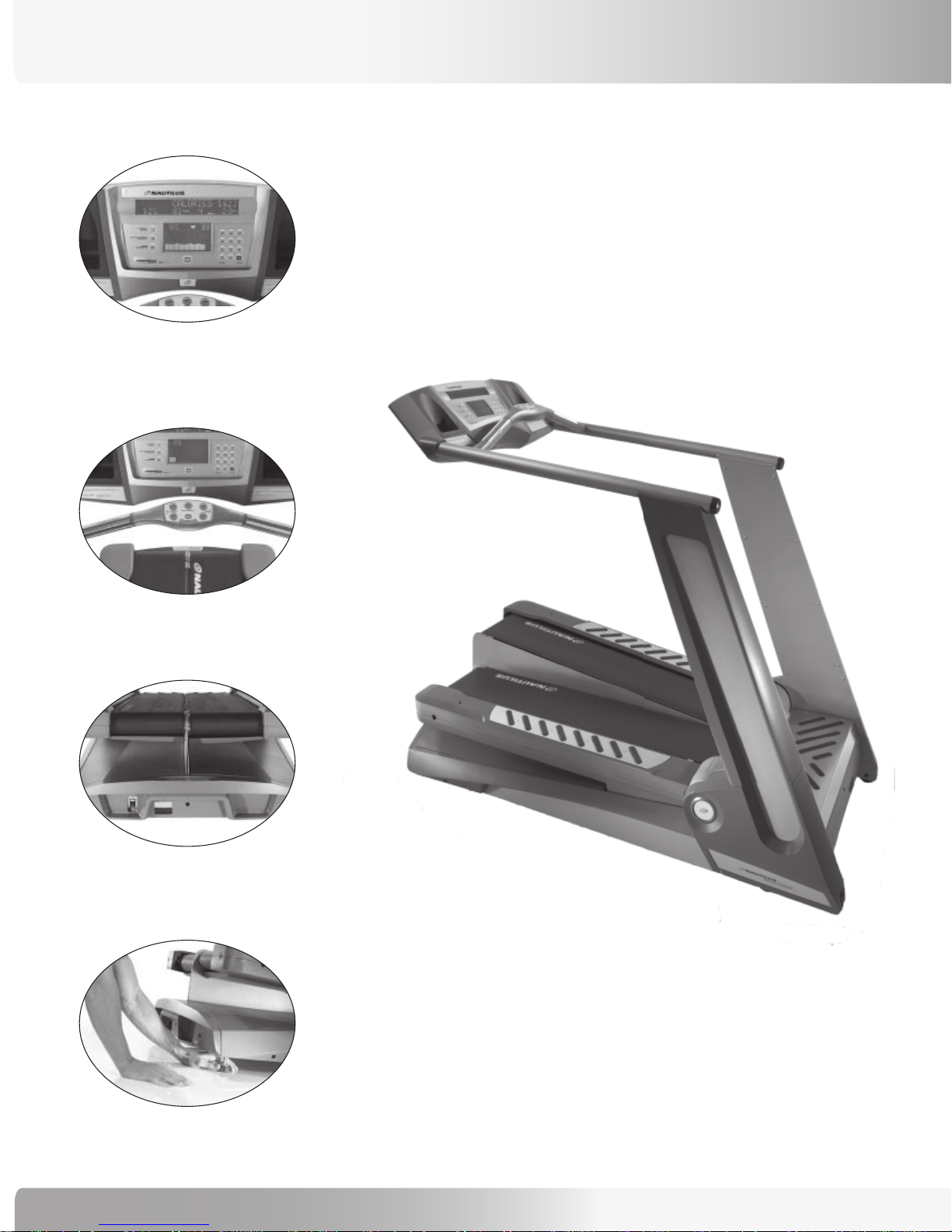
TREADCLIMBER® FEATURES
Console
Ergo Bar
Power On/Off Switch
Model: TC916
Adjustable Feet
4
Page 5
User Weight Capacity: 400 lbs (182 kg)
Speed Range: 0.5 to 6 mph (default set to 4.0 mph)
0.8 to 9.7 km/h (default set to 6.4 km/h)
Treadle Displacement Levels: MIN (half the total displacement) and
MAX (full treadle displacement)
Walk Surface (W x L): 21” x 48” defined by two separate left and right
treadmill belt assemblies (treadles), each treadle 10”
x 48” in length, with a 1” or less separation between
the belts.
(Metric Walk Surface: 53 x 122 cm.)
PRODUCT SPECIFICATIONS
Floor Space (W x L): 36” x 70” / 91.5 x 178 cm
TreadClimber® Weight: 684 lbs / 310 kg
Shipping Weight: 806 lbs / 366 kg
Power Requirements: USA: 110 Volt, 20 amp dedicated circuit.
International: 230V, 10 amp dedicated circuit
Warranty: 3 years - parts, 1 year - labor, 1 year -wear items, and
15 years - frame and AC-motor.
(May vary outside the USA.)
Regulatory Approvals:
CSA Certified, UL Listed
Meets:
FCC - Part 15
Canadian ICES-003 Regulations for Class A apparatus
Meets:
Safety - EN 60335-1
EMC Directive 89/336/EEC
Machinery Directive - 98/37/EC
Low Voltage Directive - 89/336/EEC
Model: TC916
Patent Information:
U.S. and International Patents Pending
Recycling
Do not dispose of this product as refuse. This product is to be recycled. For information
on the proper method of disposal contact a Nautilus Customer Service Representative.
Contact information is available in the Important Contact Numbers section in this manual.
Nautilus® TreadClimber® Model TC916 Assembly Manual
5
Page 6
IMPORTANT SAFETY PRECAUTIONS
7 ! 2 . ) . '
7 ! 2 . ) . '
SAVE THESE INSTRUCTIONS:
The following definition applies to the word “Warning” found throughout this manual:
Used to call attention to POTENTIAL hazards that could result in personal injury or loss
of life.
WHEN USING ELECTRICAL EQUIPMENT ALWAYS FOLLOW THESE BASIC PRECAUTIONS:
to reduce the risk of electrical shock, always unplug the external
power supply from the electrical outlet before cleaning, maintaining, or
repairing.
to reduce the risk of burns, electric shock or injury to persons read
and follow all safety warnings and instructions in this manual.
secure long hair and loose clothing before use.
do not use near water
!
READ ALL INSTRUCTIONS BEFORE USING THE MACHINE.
Read this manual in full before operating the TreadClimber® machine. Failure to follow these guidelines can produce a
serious or possible fatal electrical shock hazard or other serious injury. Consult a qualified electrician as required.
®
1. The controller Stop Key does not turn off the electrical current to the TreadClimber
TreadClimber® machine continues to draw power, even when the controller is off. To avoid electric shock, do not
remove TreadClimber® hood or place hands beneath the TreadClimber® exercise machine while the machine is plugged
into a power source.
2. Do not start the TreadClimber® machine when someone else is standing on the walk belts.
3. Keep walk speed and treadle displacement at the lowest settings when getting on and off the TreadClimber
4. Keep the area underneath and around the TreadClimber® exercise machine clear.
exercise machine. The
®
machine.
®
5. Never position the TreadClimber
objects such as furniture or other pieces of fitness equipment. Failure to keep the rear space of the machine clear can
prevent safe exit of the TreadClimber® machine in an emergency situation such as falling. Allow a minimum of four feet
behind the TreadClimber® exercise machine.
6
exercise machine with the back end (direction of belt travel) facing a wall or any other
Page 7

IMPORTANT SAFETY PRECAUTIONS
6. Before each use of this equipment, check the power receptacle for signs of damage. Do not operate the equipment if the
integrity of the power receptacle is in question.
7. To avoid potential safety and electrical problems, replace with manufacturer’s specified parts only.
8. This equipment is classified Class I, Type B, ordinary equipment. Not protected against fluid ingress. Rated for continuous
operation. Do not operate this equipment in the presence of flammable anesthetic mixtures.
9. Do not let liquid enter the controller. If it does, the controller must be inspected and tested for safety by an approved
technician before it can be used again.
10. Increased risk due to leakage current can result if this equipment is not grounded properly.
11. The TreadClimber® machine must be on an appropriate, dedicated electrical circuit. Nothing else should be connected to
the circuit.
12. Do not stand on the TreadClimber® TC916’s hood or front trim cover.
13. Close supervision is necessary whenever the machine is used by or near children, invalids, or disabled persons.
Failure to follow the conditions set forth below shall limit, to the extent allowed by law, Nautilus Inc.’s responsibility for the
safety, reliability, and performance of this equipment.
• The operator manual must be read in full by each owner and trainer before the product is first used. Each user must
be instructed in the proper use of the TreadClimber® machine and its accessories.
• Do not remove the TreadClimber® hood: dangerous voltages are present. Components are serviceable only by
qualified service personnel.
• The electrical wiring within the TreadClimber® equipment setting and the electrical installation of the TreadClimber®
machine must comply with the applicable local or provincial requirements.
• The equipment must be used in accordance with the instructions for use.
• For further information or instruction on use, maintenance or specifications, please contact your Authorized Nautilus
Fitness Dealer or Service Technician.
Nautilus® TreadClimber® Model TC916 Assembly Manual
7
Page 8

COMMERCIAL MARKET WARRANTY INFORMATION
**For warranty information outside of the United States or Canada,
contact the International office listed in the Important Contact Numbers section of this manual. **
WARRANTY INFORMATION
All Nautilus® exercise products are warranted to the commercial market purchaser to be free from defects in materials
and workmanship. Warranty coverage valid to the original purchaser only and proof of the purchase will be required. Any
product sold or placed in an application not recommended by Nautilus, Inc. will void any warranty coverage set forth by
Nautilus, Inc. warranty policies and procedures.
Time Period (May vary outside U.S.A.)
• 15 - Years - Frame and AC-motor
• 3 - Years - Mechanical and electrical parts
• 1 - Year - Labor
• 1 - Year - Wear items
What this Warranty Does Not Cover
1. Any damage, failure or loss caused by accident, misuse, neglect, abuse, improper assembly, improper maintenance or
failure to follow instructions or warnings in Owner’s Manual.
2. Use of product in a manner or environment for which it was not designed.
Limitations
The foregoing warranties are in lieu of and exclude all other warranties not expressly set forth herein, whether expressed
or implied by operation of law or otherwise, including, but not limited to, warranties of merchantability or fitness for a
particular purpose. Nautilus, Inc. shall in no event be liable for incidental or consequential losses, damages or expenses
in connection with its exercise products. Nautilus’ liability hereunder is expressly limited to the replacement of goods
not complying with this warranty or, at Nautilus’ election, to the replacement amount of the purchase price of the
exercise product in question. Some states do not permit the exclusion or limitation of implied warranties or incidental or
consequential damages, so the preceding limitations and exclusions may not apply to you.
Procedures
Warranty service will in most cases be performed by an authorized Nautilus Fitness Dealer or Service Technician. The
original purchaser must provide proof of purchase, Service calls and/or transportation to and from the Nautilus Dealer is
the responsibility of the purchaser.
1. Nautilus, Inc. will have the option to repair or replace any exercise product, which requires service.
2. Nautilus, Inc. will replace any equipment frame that is structurally defective with a new frame or replace the unit with
a unit of equal value.
3. Nautilus, Inc. is not responsible for dealer labor charges for the component changeovers completed after the labor
related warranty period stated herein.
4. If you elect to repair an exercise product or part yourself, using the services of someone other than an authorized
Nautilus Fitness Dealer or Service Technician, or use a replacement part not supplied by Nautilus, Inc., Nautilus shall
not be liable for any cost, damage, failure or loss caused by the use of such unauthorized service or parts.
8
Page 9
GETTING STARTED
Select Your Workout Area
Select the location where you are going to put your
Nautilus® TreadClimber® exercise machine carefully. The
best place for your TreadClimber® machine is on a hard, level
surface. You will need at least two feet (61 cm) on each side
and in front of your TreadClimber® machine, and at least four
feet (122 cm) behind it for dismount.
Make sure that the location you choose has a grounded,
3-prong power outlet within reach of the TreadClimber®
machine power cord, preferably to the front of the machine
where you will be less likely to step on the cord during
dismount.
NOTE: The TreadClimber® machine is designed to plug into grounded, non-GFI outlets only. To determine if your
outlet or circuit breaker is GFI, look for a test and reset button on them. If they have the test and reset
button it is a GFI outlet or circuit breaker, and therefore not suitable for plugging the TreadClimber®
machine into.
GETTING STARTED
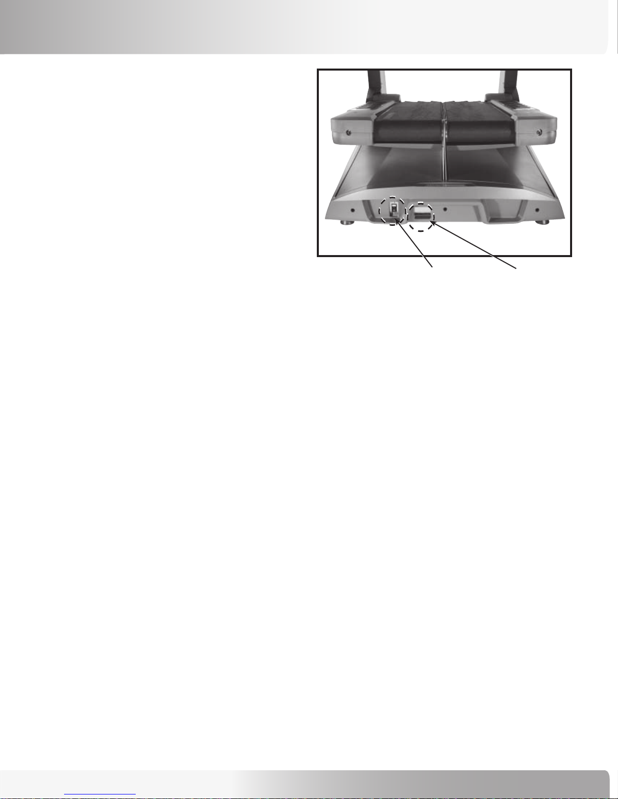
Figure 1: On/Off Switch & Power Plug
Power Plug Receptacle
The Commercial Series TreadClimber® TC916 has one power plug receptacle located on the front side of the motor pan (see
Figure 1).
Turning on the Power
The TreadClimber® exercise machine can be turned on by moving the power switch located at the front of the machine, to
the ON position (see Figure 1).
Understanding the Display and Controls
The TreadClimber® console display is a computerized panel used to operate the TreadClimber® exercise machine and see
all workout data and operational status. You should familiarize yourself with the operation of the TreadClimber® machine
and location of all keys before beginning use. Detailed descriptions and usage information is available in the TreadClimber®
Commercial Series, Model TC916, Owner’s Manual.
Nautilus® TreadClimber® Model TC916 Assembly Manual
9
Page 10

GETTING STARTED
Limited Access Control/Magnetic
Safety Stop
Limited-access control lets you restrict TreadClimber®
machine use to authorized personnel. It also lets you
stop the TreadClimber® machine in an emergency. The
magnetically-activated control is located on the bottom of
the display as shown (see Figure 2). The limited-access
control is deactivated on machines shipped from the
factory.
Magnetic Key Safety Stop Activation
To activate the limited-access control and restrict access,
place the magnetic safety stop key supplied with the
TreadClimber® machine in the designated area located
below the display (see Figure 3).
Figure 2
The magnetic key will activate the control. If you remove
the key, the TreadClimber® treadle belts will stop and the
console controller will not respond to any key presses.
Accumulated values will remain on the display until you
turn off the power, or press [CLEAR].
The console will display a message, “REPLACE MAGNET”
when you remove the magnetic key from its designated
area. You must replace the key or deactivate the control
to start the walk belt.
Figure 3
10
Page 11
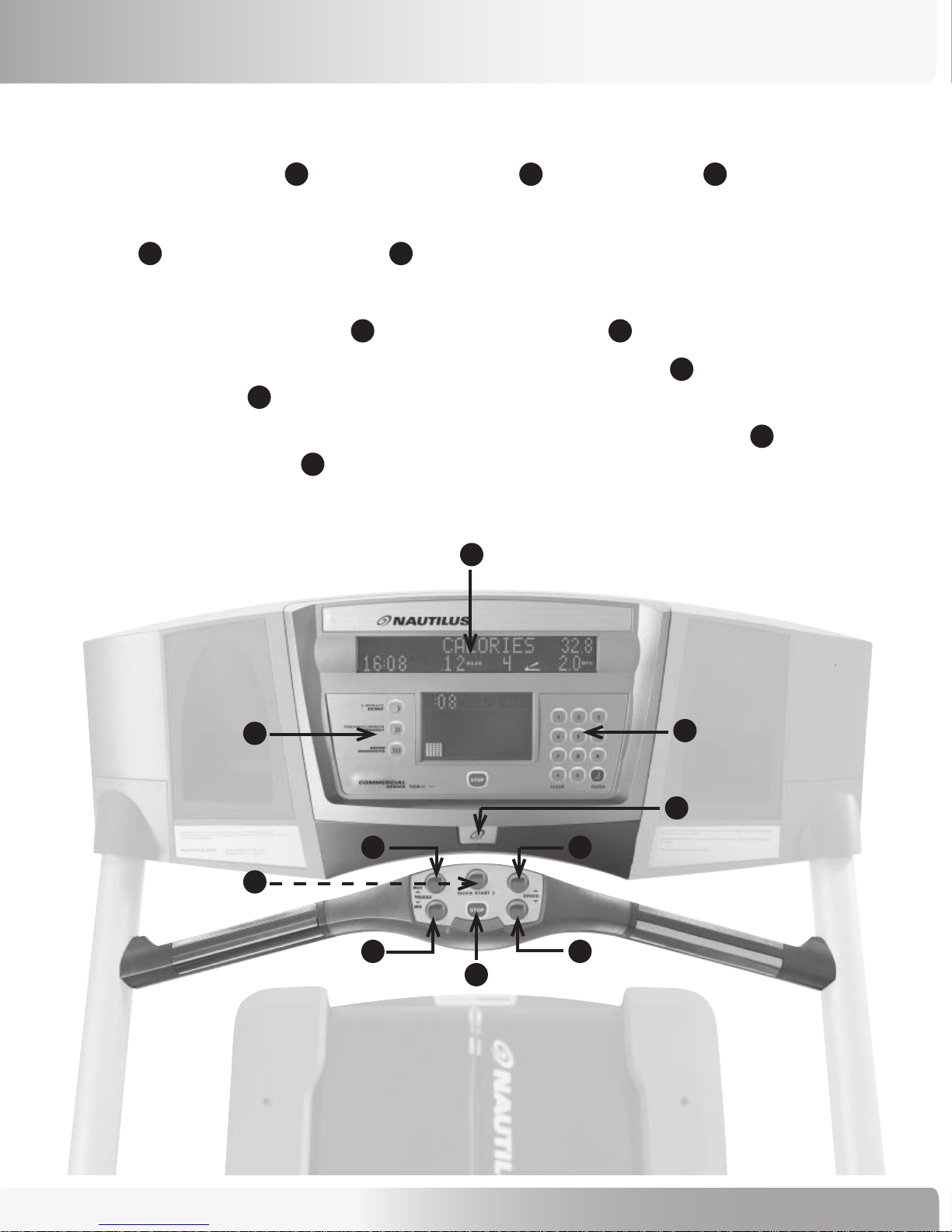
Quick Start Guide
To Start:
GETTING STARTED
Insert the Magnetic Safety Stop Key and press the [QUICK START] key , or select a program key .
To Stop:
Press [STOP] to pause the workout. Press [STOP] again to end the workout.
During the workout:
• After selecting a program, follow the Display prompts and use the numeric keypad to enter information.
• Walk speed may be changed at any time during the workout by pressing the [Speed: UP] key to increase the walk speed, or
the [Speed: DOWN] key to decrease the walk speed.
• Treadle displacement may be changed at any time during the workout by pressing the [Treadle: MAX] key to increase the
height, or the [Treadle: MIN] key to decrease the height.
WARNING: For detailed information on use and safety, refer to your Owner’s Manual file located on CD ROM.
4
1
4
65
8
10
32
7
9
5
3
6
1
9
7
2
10
8
4
Nautilus® TreadClimber® Model TC916 Assembly Manual
11
Page 12
MOVING INSTRUCTIONS
7 ! 2 . ) . '
Moving your Fully Assembled TreadClimber® TC916
TO REDUCE THE RISK OF INJURY TO PERSONS READ AND
FOLLOW ALL SAFETY WARNINGS AND INSTRUCTIONS IN THIS
MANUAL.
TWO PEOPLE ARE REQUIRED TO UNLOAD AND MOVE THE
TREADCLIMBER
THE FACILITY.
DELIVERY LOGISTICS
The TreadClimber® TC916 may be delivered fully-assembled, shipped on a pallet crate, and blanket wrapped;
®
TC916 EXERCISE MACHINE INTO POSITION IN
• Pallet crate shipping weight: 806 pounds
• Unit weight: 684 pounds
- OR -
Delivered in a one box configuration, requiring assembly.
• Boxed Unit shipping weight: 850 pounds
• Unit weight: 684 pounds
MOVING INSTRUCTIONS FOR FULLY ASSEMBLED UNIT INCLUDE:
1. Taking unit off pallet crate.
2. Moving unit into position in facility, if door ways are greater than 40 inches (101 cm) wide.
3. Disassembly of Upright Unit Instructions, if door ways are less than 40 inches (101 cm) wide.
4. Moving Tool Information to assist with moving fully assembled TreadClimber® unit.
ASSEMBLY INSTRUCTIONS FOR ONE BOX CONFIGURATION UNIT INCLUDE:
1. Unpacking Instructions.
2. Assembly Instructions.
12
Page 13
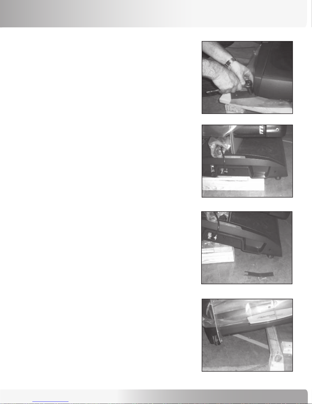
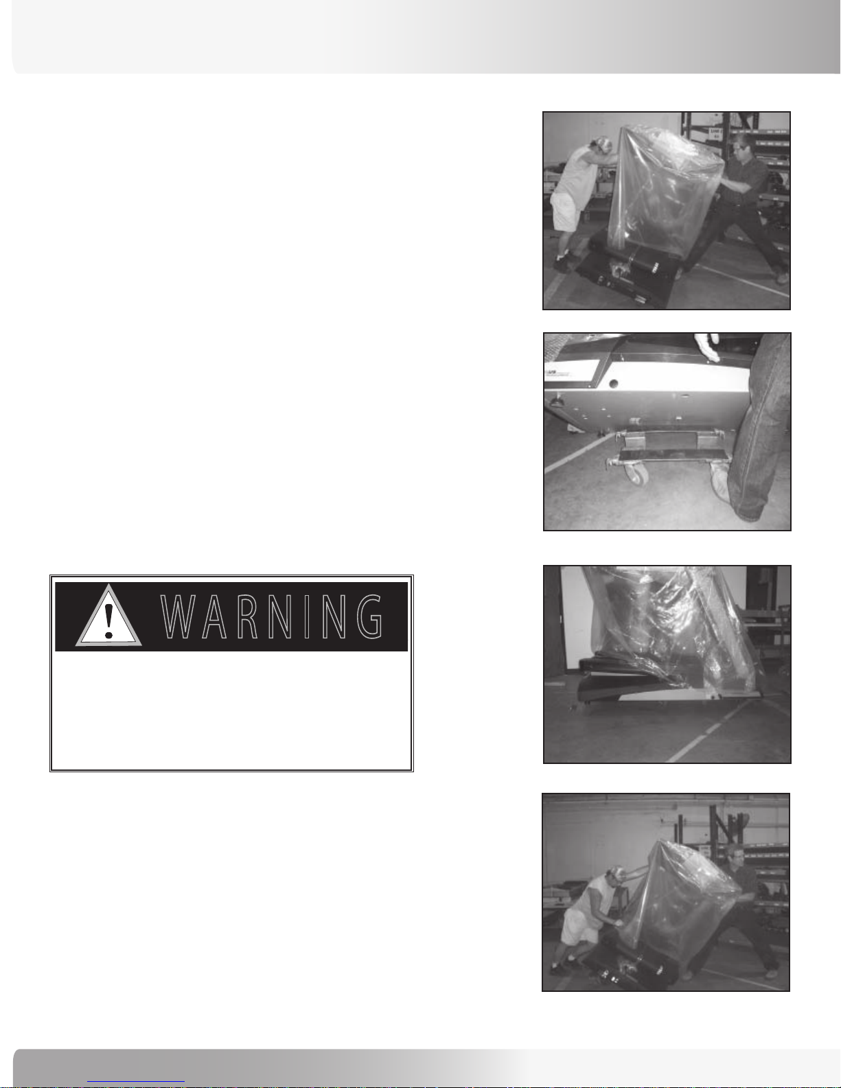
Removing Machine from Pallet
Tools Needed:
MOVING INSTRUCTIONS
7/16 Socket
Ratchet
Step 1: Remove TC916 from pallet by removing restraining
stabilizer brackets with socket and ratchet from
stabilizer feet (see Figure 1).
Step 2: Manually slide TC916 to one side of the pallet -
over hanging approximately 12 to 15 inches off the
side of the pallet (see Figure 2).
Step 3: Tilt unit to side and slide edge of frame to ground
(see Figure 3).
Step 4: Tilt to 40 degrees and move pallet out of the way,
lowering TC916 to ground (see Figure 4).
NOTE: If removing the TreadClimber® TC916 from
pallet you should be placing the unit in its
final position in the facility when removing
it from the pallet.
Figure 1
Figure 2
Figure 3
Figure 4
Nautilus® TreadClimber® Model TC916 Assembly Manual
13
Page 14
MOVING INSTRUCTIONS
7 ! 2 . ) . '
Moving Unit into Position in Facility
NOTE: Perform the following moving procedure to position
your TreadClimber® Model TC916 in your facility if
your door ways are greater than 40 inches wide.
Tools Needed:
7/16 Socket
Ratchet
Moving Dolly
Lift Bar
Step 1: Remove TC916 from pallet by performing steps
in section “Removing Machine from Pallet” in
this manual.
Figure 1
Figure 2
Step 2: Tilt to 40 degrees (see Figure 1).
place 4-wheel moving dolly under center of
TreadClimber® frame (see Figure 2).
WHEN LOWERING THE TREADCLIMBER®
UNIT ONTO DOLLY BE SURE THAT THE
CASTORS ARE LOCKED SO THAT IT DOES
NOT MOVE OUT FROM UNDER THE
TREADCLIMBER
Step 3: Carefully, lower the TreadClimber
onto 4-wheel moving dolly (see Figure 3).
®
UNIT.
While tilted
®
Model TC916
Figure 3
Step 4:
14
Once in position in the facility, prepare to
remove unit from 4-wheel dolly by locking
castors.
Figure 4
Page 15

Step 5: Carefully tilt TreadClimber®machine onto one-side
of frame towards ground (see Figure 4).
Step 6: Tilt unit to 40 degrees and remove moving dolly.
Step 7: Place Moving Tool under the machine according to
the “Moving Tool Instructions” section located in
this manual and wheel the unit into position.
MOVING INSTRUCTIONS
Nautilus® TreadClimber® Model TC916 Assembly Manual
15
Page 16

7 ! 2 . ) . '
! 4 4 % . 4 ) / .
$ ! . ' % 2
MOVING INSTRUCTIONS
Disassembly of Upright Unit
IMPORTANT INFORMATION TO READ
BEFORE DISASSEMBLING UPRIGHT UNIT.
During delivery of this unit it may become necessary to disassemble the upright portion of the unit to reduce the size and
weight. The upright portion of the unit has wheels integrated into it, making it possible to wheel it away from the base
and handle it as a separate unit.
Only use this option if delivery of the unit is not possible using one of the two preferred moving options:
Moving unit into position in facility, if door ways are greater than 40 inches (101 cm) wide, or
One boxed configuration, requiring assembly before use.
to avoid electrical shock or damage to the unit you
must power oFF the unit and make sure all power has
been drained From the unit and capacitors by ensuring
there are no lighted leds on the console.
detaching and moving the upright portion oF this
product requires two people! you must have a minimum
oF two people to properly support the heavy upright
structure so the console does not Fall and cause
damage to the unit.
16
Page 17

1.0 REMOVING REAR STEP
7 ! 2 . ) . '
MOVING INSTRUCTIONS
Tools Needed:
• Phillips head screw driver
• Magnetic 3/8” Nut Driver with long shaft
• Magnetic 3/8” socket
• Ratchet
Step 1: Unplug the unit from the power source and ensure
that all power has been drained from the unit.
Step 2: Remove two (2) middle screws (see Figure 1-1).
Step 3: Slide step cover plate back to remove
(see Figure 1-2).
Step 4: Depending upon the Step Weldment style of the
unit:
4A: Remove the four corner screws and slide the
weldment outward (see Figure 1-3).
- OR -
Figure 1-1
Figure 1-2
4B: Remove the two side screws. One screw on
left and right, then slide the weldment outward
(see Figure 1-4).
Removing the step cover plate provides access to the I/O
cables needed for the next step.
to avoid electrical shock or damage
to the unit you must power oFF the
unit and make sure all power has been
drained From the unit and capacitors by
ensuring there are no lighted leds on
the console.
Figure 1-3
Four Screws
Figure 1-4
Two Screws
Nautilus® TreadClimber® Model TC916 Assembly Manual
17
Page 18

7 ! 2 . ) . '
MOVING INSTRUCTIONS
2.0 REMOVING UPRIGHTS
Tools Needed:
• Phillips head screw driver
• 5/32 Allen wrench
• 3/4 inch wrench or socket
• 1/2 inch drive Ratchet
• 1/2 inch drive Torque wrench
Step 1: Remove for the four Button head screws at-
taching the console to the Upright weldment,
disconnect the cables and remove the console
Step 2: Remove the Rear Step as directed in Section 1:
Step 3: Disconnect the Base Cable (P/N - 17826) from
from the machine.
Removing Rear Step.
the Handrail Cable (P/N - 17824) located in the
lower left hand corner (see Figures 2-1 and 2-2).
Figure 2-1
Figure 2-2
Step 4:
Remove rear plastic cover by loosening six (6)
screws (see Figure 2-3 and Figure 2-4).
Step 5:
Remove right and left lower plastic parts by
removing seven (7) screws located on the right
and left upright inside panels (see Figure 2-5 and
Figure 2-6).
Step 6:
Step 7:
Remove the four (4) upright bolts (see Figure 2-7)
Wheel upright structure away to safe location
(wheels are integrated into upright portion of
unit).
NOTE: To replace the upright unit, reverse the
directions. The four handrail screws are
to be torqued to a setting of 75 ft. lbs.
detaching and moving the upright portion oF
Figure 2-3
Figure 2-5:
Lower plastic parts.
Figure 2-4:
Rear plastic cover off.
Figure 2-6
this product requires two people! you must
have a minimum oF two people to properly
support the heavy upright structure so the
console does not Fall and cause damage to
the unit.
18
Figure 2-7
Page 19

NOTE: You should only use this step if you need to
rotate the lower base unit up onto its side to
transport it.
MOVING INSTRUCTIONS
3.0 REMOVING BASE PLASTIC
Tools Needed: 1/8 Allen bit
Step 1: Remove three (3) front plastic screws
(see Figure 3-1).
Step 2: Remove right and left side plastic covers - four (4)
screws each side (see Figure 3-2).
Step 3: Remove right and left side pan covers - two (2)
screws each side (see Figure 3-3 and Figure 3-4).
Figure 3-1
Figure 3-2
Figure 3-3
Figure 3-4:
Pan without
covers.
Nautilus® TreadClimber® Model TC916 Assembly Manual
19
Page 20

MOVING INSTRUCTIONS
Moving Tool Information
MOVING TOOL PARTS:
The following parts are shown in the figure to the
right, in order listed:
• Wheel Bar – one frame, two wheels, two clevis clips
• Caster Cart – one base, two wheels
• Lifting Tool – one piece
• Two 4x4x6 inch (ca. 10x10x15.5 cm) Blocks of Wood
- not pictured
BEFORE MOVING THE TC916 UNIT:
1 - Make sure the power cord is not running under
the machine.
USAGE DIRECTIONS:
Step 1: Lift the right side of the TC916 and brace with a
4x4x6 inch (ca. 10x10x15.5 cm) block of wood near
the middle of the machine.
Step 2:
Lift the left side of the TC916 and brace with a
4x4x6 inch (ca. 10x10x15.5 cm) block of wood near
the middle of the machine.
CLEVIS CLIP
Caster Cart
FRAME
Wheel Bar
Figure 1
WHEEL
Step 3: Slide the Wheel Bar under the machine near the
front of the TC916. Tilt the TC916 towards the rear,
raising the front of the machine to provide room to
slide the Wheel Bar underneath.
Step 4: Tilt the machine forward, towards the Console and
slide the Caster Cart under the rear of the machine
(see Figure 1). Position the Caster Cart under the
machine flush with the bottom of the frame so that
it hooks between the frame and the leveling pads.
20
Figure 2
Page 21

MOVING INSTRUCTIONS
Step 5: On the right side, lift the machine and remove the block of wood, lowering the machine onto the Caster Cart and
Wheel Bar, ensuring the wheels are straight.
Step 6
: On the left side, lift the machine and remove the block of wood, lowering the machine onto the Caster Cart and
Wheel Bar, ensuring the wheels are straight (see Figure 2).
Step 7:
The machine is now ready to move.
a. This moving tool is designed to move the TC916 in and out of a row of machines. It is not intended to move the
machine long distances or over obstacles.
b. Once the machine is out of the row other moving methods can be employed to move the machine to another room
or in/out of the club.
c. This tool is designed as a service aid and not for transportation.
d. DO NOT operate the TC916 while it is on the Caster Cart.
Step 8:
When service is completed or the machine needs to be operated place the machine where it is desired and reverse
the steps removing the Caster Cart and Wheel Bar.
Nautilus® TreadClimber® Model TC916 Assembly Manual
21
Page 22

ASSEMBLY INSTRUCTIONS
7 ! 2 . ) . '
BEFORE YOU ASSEMBLE
Basic Assembly Principles
Here are a few basic assembly tips that can make
®
assembly of your Nautilus
exercise machine quick and easy.
1. You can make the assembly process go faster by
gathering the pieces you need for each step prior to
starting the step.
2. As a general rule, and for all bolts and locknuts on your
®
Nautilus
toward the right will tighten, turning towards the left will
loosen. An easy way to remember this is by remembering
the expression, “Lefty loosey, righty tighty.”
TreadClimber® exercise machine, turning
Commercial TreadClimber®
3. Gather all of the tools needed for assembly before
beginning. The tools are listed in the Hardware and
Tools list of this manual. You may find the use of a utility
knife or scissors beneficial during the unpacking and
assembly process.
TO REDUCE THE RISK OF INJURY TO PERSONS READ AND
FOLLOW ALL SAFETY WARNINGS AND INSTRUCTIONS IN THIS
MANUAL.
TWO PEOPLE ARE REQUIRED TO UNLOAD, UNPACK, ASSEMBLE
AND MOVE THE TREADCLIMBER
POSITION.
®
TC916 EXERCISE MACHINE INTO
22
Page 23

HARDWARE AND TOOL LIST
Tools needed: (not provided)
• 3/4 inch Socket, for a 1/2 inch Drive Ratchet
• 1/2 inch drive Ratchet
• 7/32 Allen bit
• 5/32 Allen bit
• 1/8 Allen bit
• Torque wrench with 1/2 inch drive
• Phillips screw driver
*Hardware not illustrated to actual size.
ASSEMBLY INSTRUCTIONS
Qty: 4
Descr: Screw, .500-13 x 3.25 HHC
Part Number: 17683
Qty: 8
Descr: Screw, .375 -16 x 1.00, BH, SS
Part Number: 25796
Qty: 4
Descr: Washer, .50 SAE Flat
Part Number: 22091
Qty: 4
Descr: Screw, 1/4 - 20 x 3/8 Button, HD, SO
Part Number: 24162
Qty: 36
Descr: Screw, Button HD Cap, 10-32 x 5 / 8L
Part Number: 17815
Qty: 2
Descr: Screw, #10-32 x 0.375 Flat Hd Phillips
Part Number: 17695
Qty: 4
Descr: Washer, Split Lock .50
Part Number: 22222
Qty: 8
Descr: Internal/External Washer .375
Part Number: 17775-007
Qty: 36
Descr: Washer, Lock, Int. Star, #10, SS
Part Number: 17578
Nautilus® TreadClimber® Model TC916 Assembly Manual
23
Page 24

ASSEMBLY INSTRUCTIONS
Parts List Reference Guide
NOT ILLUSTRATED:
Qty: 1
Descr: Assembly/Owner’s Manual Kit and Hardware Kit Bag
Qty: 1
Descr: Power cord
Part Number: DEPENDING UPON YOUR COUNTRY AND REGION YOU WILL HAVE
A POWER CORD CONFIGURED TO YOUR COUNTRY’S/REGION’S
POWER SUPPLY. IF THE POWER CORD IS MISSING OR NOT
COMPATIBLE CONTACT A NAUTILUS REPRESENTATIVE FOR A
REPLACEMENT.
Qty: 1
Descr: Console Assembly
Part Number: 17670 - Domestic
17835 - TV, Domestic
17837 - TV, International
Qty: 1
Descr: Left Upright Plastic Cover
Part Number: 17669
Qty: 1
Descr: Left Bottom Plastic Pivot Cover
Part Number: 17918
Qty: 1
Descr: Right Upright Plastic Cover
Part Number: 17668
Qty: 1
Descr: Right Bottom Plastic Pivot Cover
Part Number: 17919
Qty: 1
Descr: Rear Step Cover
Part Number: 17733
Qty: 1
Descr: Rear Step Weldment
Part Number: 17591
Qty: 1
Descr: One Rear Motor Cover
Part Number: 17874
24
Page 25

ASSEMBLY INSTRUCTIONS
Qty: 1
Descr: TC916 TreadClimber® Base Assembly
Part Number: 17500
Qty: 1
Descr: TC916 TreadClimber® Handrail Assembly
Part Number: 17793
Qty: 1
Descr: TC916 TreadClimber® Handrail Upright Support
Assembly
Part Number: 17794
Nautilus® TreadClimber® Model TC916 Assembly Manual
25
Page 26

ASSEMBLY INSTRUCTIONS
Unpacking Guide
The following instructions provide direction in unpacking the boxed unit for the Nautilus® Commercial Series
TreadClimber® model TC916.
Step 1: Opening Crate
Tools:
• Scissors or utility knife
1-1 Remove the outer cardboard to reveal the
contents of crate.
Step 2: Unpacking Crate
Tools:
• Scissors or utility knife
2-1 Remove the three enclosed boxes within the
crate and place to the side.
2-2 Remove the Upper Upright Weldment and Lower
Upright Weldment.
26
Upper Upright Weldment
Lower Upright Weldment
Page 27

Step 3: Verifying Box Contents
Locate the following for this step:
ASSEMBLY INSTRUCTIONS
• Box 1 - Parts Master Carton
• Box 2 - Top Plate Carton
• Box 3 - Short Side Panel Carton
Tools:
• Scissors or utility knife
3-1 Verify the contents of Box 1: “PARTS MASTER
CARTON”.
The carton should contain the following:
• Box #1A - Left and right top Upright Covers.
Marked “Long Side Panels” on the box.
• Box #1B - Console. Marked “Control Panel”
on the box.
• Rear Step weldment (see Figure 1).
• Hardware Bag containing: TV Cable (if
applicable), Owners Manual, Magnet,
Cord Clamp, Grounding Harness, 5/16 Allen
Wrench, Service Bulletin, and hardware
for attaching the Weldment, Console, and
Covers.
3-2 Verify the contents of Box 2: “TOP PLATE
CARTON”.
BOX 1
BOX 2
BOX 3
Figure 1
Figure 2
• Rear Step, insert molded (see Figure 2).
• Lower Front Cover (see Figure 3).
3-3 Verify the contents of Box 3: “SHORT SIDE
PANEL CARTON”.
• Left and Right Pivot Covers (see Figure 4).
Figure 3
Figure 4
Nautilus® TreadClimber® Model TC916 Assembly Manual
27
Page 28

ASSEMBLY INSTRUCTIONS
Step 4: Dismantling Crate
Tools:
• Hammer
4-1 Carefully dismantle the wooden crate to allow
access to the bottom half of the TreadClimber®
TC916 frame.
NOTE: The TreadClimber
®
TC916 base frame should
be close to the final location for the fully
assembled machine during this step.
Step 5: Removing from Pallet
Tools:
• 7/16 Socket
• Ratchet
5-1 Remove TC916 from pallet by removing
restraining stabilizer brackets with socket and
ratchet from stabilizer feet (see Figure 1).
Remove wooden supports
around base assembly.
Figure 1
5-2 Manually slide TC916 to one side of the pallet
- over hanging approximately 12 to 15 inches off
the side of the pallet (see Figure 2).
5-3 Tilt unit to side and slide edge of frame to ground
(see Figure 3).
5-4 Tilt to 40 degrees and move pallet out of the way,
lowering TC916 to ground.
NOTE: When removing the TreadClimber
from pallet you should be placing the unit in its
final position in the facility.
28
®
TC916
Figure 2
Figure 3
Page 29

ASSEMBLY INSTRUCTIONS
Assembly Guide
The following instructions provide direction in assembling the boxed units for the Nautilus® Commercial Series
TreadClimber® model TC916. All instructions in the manual are given with the orientation of standing on the
TreadClimber® facing the console. The console is the front, while the rear roller is the back.
Step 1: Connecting Wiring Harness
Locate the following for this step:
Parts:
• Base Assembly (P/N - 17500)
• Handrail Upright Support Assembly (P/N - 17794)
1-1 Locate the three Ground Wire Straps on either
side of the Base Assembly, making sure that the
wire is extended towards the front of the unit
and doesn’t become hidden behind the Handrail
Upright Support during Step 1-2.
1-2 With the help of another person, connect wiring
harness (P/N - 17826) from the TreadClimber
TC916 Base Assembly to the wiring harness
(P/N - 17824) in the Handrail Upright Support
Assembly. See Figure 1.
®
Figure 1: Connecting Wiring Harness
Handrail Upright Support Assembly
Base Assembly
Ground Wire Strap
Locations
Wiring Harness
Connection
Nautilus® TreadClimber® Model TC916 Assembly Manual
29
Page 30

ASSEMBLY INSTRUCTIONS
Step 2: Connecting Handrail Support to Base Assembly
Locate the following for this step:
Parts:
• Assembly from Step 1
Hardware:
• 4 bolts (P/N 17683)
• 4 Lock Washers (P/N - 22222)
• 4 Washers (P/N 22091)
Tools:
• 3/4 inch socket for 1/2 drive
• Torque wrench (1/2 inch), set at 75 ft. lbs. (100 NM)
• 1/2 inch drive Ratchet
2-1 On right side, connect Handrail Upright Support
Assembly to TreadClimber
bolts, 2 lock washers, and 2 washers. Finger tighten
only, being careful not to pinch wiring harness. See
Figure 2 and Figure 2A.
®
Base Assembly using 2
Figure 2: Connecting Handrail Support to Base Assembly
Handrail Upright Support Assembly
Base
Assembly
2-2 Repeat Step 2-1 on the left side.
2-3 Using the drive ratchet, tighten the 2 lower bolts on
each side first, and then the 2 upper bolts on each
side installed in Step 2-1 and Step 2-2. Then use the
Torque wrench to set the tightness for all 4 bolts to 75
ft. lbs. (100 NM)
IMPORTANT! M A K E S U RE T H AT THE WIRI N G
HARN E S S C A B LES DO N OT BECO M E P I N CHED.
Washer
Lock Washer
Bolt
Figure 2A: Close-up of hardware stack.
30
Page 31

ASSEMBLY INSTRUCTIONS
Step 3: Connecting Ground Wire Straps to Base Assembly
Locate the following for this step:
Parts:
• Assembly from Step 2
• 3 Grounding Straps
Hardware:
• 4 Self-tapping screws - .25 x .50 (P/N 22139)
• 5 Lock Washers (P/N - 41260)
Tools:
• Phillips screw driver
3-1 Remove the 3 Grounding straps, 4 Self-Tapping Screws,
and 5 Lock Washers from the parts bag.
3-2 Attach one end of a grounding strap to the right side
of base frame with one screw and lock washer. (See
Figure 3 - Grounding Strap #1.)
Figure 3: Connecting Ground Wire Straps
Ground Wire
Strap - #3
Ground Wire
Strap - #2
Ground Wire
Strap - #1
IMPORTANT! PL A CE R ING T ERMI N A L OF THE
CABL E BE T WEEN THE SCR E W AND LOC K WA SHER .
3-3 Attach the other end of grounding strap to the cross
bar of the lower Upright weldment with a screw and
lock washer . (See Figure 3 - Grounding Strap #1.)
3-4 Attach one end of second grounding strap to the left
side of base frame with one screw and washer. (See
Figure 3 - Grounding Strap #2.)
3-5 Attach the other end of second grounding strap with
one end of third grounding strap to the cross bar of
the lower Upright weldment with a screw and two
washers. (See Figure 3 - Grounding Strap #2 and #3,
and Figure 3A.)
IMPORTANT! L E AVE OT H ER E ND O F TH I RD
GR O UNDING STRAP FREE . I T WIL L BE INSTALLE D
IN STEP 10 O F ASSE M BLY PROCE S S.
Figure 3A: Connecting Ground Wire Straps #2 & #3
Ground Wire Strap - #3
Ground Wire
Strap connection
between - #2 & #3.
Ground Wire Strap - #2
Nautilus® TreadClimber® Model TC916 Assembly Manual
31
Page 32

ASSEMBLY INSTRUCTIONS
Step 4: Connecting Wiring Harness from Upright Supports to Handrails
Locate the following for this step:
Parts:
• Assembly from Step 3
• Handrail Assembly (P/N - 17793)
4-1 Connect the wiring harness (P/N - 17824) from the
Handrail Upright Support Assembly (P/N - 17794) to
the Handrail Assembly. See Figure 4.
Wiring Harness
Connection
Figure 4: Connecting Wiring Harness to Handrail
Handrail Assembly
NOTE: Carefully slide the Upper Upright Cables (TV
Cable if applicable) inside Handrail Upright
Support Assembly, until they come out the
bottom as you place the Handrail Assembly
on.
32
Base Assembly
Page 33

ASSEMBLY INSTRUCTIONS
Step 5: Connecting Handrail Support to Base Assembly
Locate the following for this step:
Parts:
• Assembly from Step 4
Hardware:
• 8 screws (P/N 25796)
• 8 washers (P/N 17775-007)
Tools:
• 7/32 Allen bit
5-1 Bolt Handrail Assembly (P/N - 17793) to Handrail
Upright Support Assembly (P/N - 17794) using 8
screws and 8 washers. See Figure 5.
IMPORTANT! M A K E S U RE T H AT THE WIRI N G
HARN E S S C A B LES DO N OT BECO M E P I N CHED.
Figure 5: Connecting Handrail Support to Base Assembly
Handrail Assembly
Screw
Washer
Base Assembly
Nautilus® TreadClimber® Model TC916 Assembly Manual
33
Page 34

ASSEMBLY INSTRUCTIONS
Step 6: Connecting Wiring Harness to Console
Locate the following for this step:
Parts:
• Assembly from Step 5
• Console (P/N 17670)
6-1 Connect the wiring harness from the Handrail
Upright Support Assembly (P/N - 17794) to Console
(P/N - 17670) on the left and right side. See Figure 6.
NOTE: If TV Cable present, connect to mating cable
from the console.
6-2 Being careful not to pinch the wiring harness, slide
the console into the open tubes of the handlebar.
IMPORTANT! M A K E S U RE T H AT THE WIRI N G
HARN E S S C A B LES DO N OT BECO M E P I N CHED.
Figure 6: Connecting Wiring Harness to Console
Console
Handrail Assembly
Base Assembly
Wiring Harness
Connection
34
Page 35

Step 7: Securing Console
ASSEMBLY INSTRUCTIONS
Locate the following for this step:
Parts:
• Assembly from Step 6
Hardware:
• 4 screws (P/N 24162)
Tools:
• 5/32 Allen bit
7-1 Align the holes on the tubing of the console with
the holes on the handrail and secure Console (P/N
- 17670) in place using 4 screws (P/N - 24162). See
Figure 7.
Figure 7: Securing Console
Console
Handrail Assembly
Screws
Base Assembly
Step 8: Attaching Lower Plastic Covers
Locate the following for this step:
Parts:
• Assembly from Step 7
• Right Bottom Plastic Pivot Cover (P/N 17919)
• Left Bot tom Plastic Pivot Cover (P/N 17918)
Hardware:
• 14 screws (P/N 17815)
• 14 washers (P/N 17578)
Tools:
• 1/8 Allen bit
8-1 On the right side, attach Right Bottom Plastic Pivot
Cover (P/N - 17919) using the 7 screws (P/N - 17815)
and 7 washers (P/N - 17578). See Figure 8.
8-2 Repeat Step 8-1 on the left side.
Figure 8: Attaching Lower Plastic Covers
Left Bot tom
Plastic Pivot
Cover
Screws
Washers
Base Assembly
Right Bottom
Plastic Pivot
Cover
Nautilus® TreadClimber® Model TC916 Assembly Manual
35
Page 36

ASSEMBLY INSTRUCTIONS
Step 9: Attaching Rear Motor Cover
Locate the following for this step:
Parts:
• Assembly from Step 8
• Rear Motor Cover (P/N 17874)
Hardware:
• 6 screws (P/N - 17815)
• 6 washers (P/N 17578)
Tools:
• Phillips screw driver
9-1 Attach the Rear Motor Cover using 6 screws and 6
washers. See Figure 9.
IMPORTANT! M A K E S U RE T H AT FR EE E ND
OF GRO U N DING STR A P I N S TA L L ED IN S T EP 3
IS ABOV E RE AR MOT OR C OVER . IT WILL BE
IN S TALL E D I N STE P 10 O F A S S EMBLY PRO C ESS.
Figure 9: Attaching Rear Motor Cover
Screws
Base Assembly
Rear Motor Cover
Washers
36
Page 37

Step 10: Attaching Rear Step Assembly
ASSEMBLY INSTRUCTIONS
Locate the following for this step:
Parts:
• Assembly from Step 9
• Rear Step Weldment (P/N 17591)
• Rear Step Cover (P/N 17733)
Hardware:
• 2 screws (P/N - 17809)
• 2 washers (P/N - 22637)
• 2 screws (P/N - 17695)
• 1 Self-tapping screws - .25 x .50 (P/N 22139)
• 1 Lock Washers (P/N - 41260)
Tools:
• Phillips screw driver
• 3/8 Socket driver
10-1 Attach the Rear Step Weldment to the Base
Assembly using two screws (P/N - 17809) and two
washers (P/N - 22637).
Figure 10: Attaching Rear Step Cover
Screws
Rear Step Cover
Base Assembly
Rear Step
Weldment
Figure 10-A: Attaching Grounding Strap
NOTE: Due to the tight spacing a magnetic tool is
recommended during this step.
10-2 Secure the loose end of third grounding cable that
was installed in Step 3 to the Step weldment on the
left side with a Self-tapping Screw and Lock Washer.
(See figure 10-A.)
10-3 At tach the Rear Step Cover to the Rear Step Frame
(P/N - 17591) using two screws (P/N - 17695). See
Figure 10.
Ground Wire
Strap - #3
Third Ground Wire Strap
connection to Rear Step
Weldment
Rear Step
Weldment
Nautilus® TreadClimber® Model TC916 Assembly Manual
37
Page 38

ASSEMBLY INSTRUCTIONS
Step 11: Attaching Upright Plastic Covers
Locate the following for this step:
Parts:
• Assembly from Step 10
• Right Upright Plastic Cover (P/N - 17668)
• Left Upright Plastic Cover (P/N - 17669)
Hardware:
• 16 screws (P/N - 17815)
• 16 washers (P/N - 17578)
Tools:
• 1/8 Allen bit
11-1 On the right side, attach the Right Upright Plastic
Cover using 8 screws (P/N - 17815) and 8 washers
(P/N - 17578). See Figure 10.
Figure 11: Attaching Upright Plastic Covers
Left Upright
Plastic Cover
Washer
Screw
11-2 Repeat Step 11-1 on the left side of the unit.
Step 12: Installing Power Cord
Locate the following for this step:
Parts:
• Assembly from Step 11
• Power Cord
12-1 Locate the power cord for your region.
12-2 Attach the power cord to the AC Inlet on the
Front Motor Pan and then to the wall outlet
(see Figure 12).
Right Upright
Plastic Cover
Figure 12: Installing Power Cord
38
Power Cord Outlet
Page 39

7 ! 2 . ) . '
Step 13: Turning on the Power
ASSEMBLY INSTRUCTIONS
Locate the following for this step:
Parts:
• Assembly from Step 12
13-1 Locate the power switch at the front of the
machine.
13-2 Move the power switch to the ON position (see
Figure 13).
IMPORTANT! REFE R T O T H E O W N ER’S
MANUA L FO R DE TAIL E D I N S T RUCTIO N S A ND
IN F O RMAT ION O N H O W TO U SE A N D CARE FOR
YO UR T RE A D CLIM B ER® COMME RCIAL SER I ES
EXER C ISE M ACHI N E, M O DEL TC916.
Figure 13: Turning on Power
Power Switch
Step 14: Inspecting Assembly
Congratulations!
Now that you have assembled your Nautilus
TreadClimber® Model TC916, it is VERY IMPORTANT to
tighten all screws and bolts, and visually inspect the
TreadClimber® exercise machine. If your TreadClimber®
machine sits unevenly you may adjust the leveling feet
on each corner of the machine by hand to make the unit
stable on your floor. Make sure that your TreadClimber
exercise machine has been assembled correctly and
securely, and that there are no loose, uncovered, or
unattached parts prior to use.
®
Failure to visually check and test assembly
before use can cause damage to the
®
Nautilus
®
exercise machine and serious injury
TreadClimber® Model TC916
to users and bystanders and can also
compromise the effectiveness of your
exercise program.
Nautilus® TreadClimber® Model TC916 Assembly Manual
39
Page 40

BELT TENSION AND ALIGNMENT
During initial installation, within the first 1- to -4 hours of
use, and daily for the first week of use, the treadle belts on
the TreadClimber® TC916 need the tension and alignment
inspected and adjusted. As the TreadClimber® treadle belts
stretch through use it will become necessary to tension the
belts. Adjust the belt tension whenever the belt slips or
moves unsteadily during operation. Failure to follow these
instructions could seriously impact performance.
Alignment adjustment
IMPORTANT- Do not over tighten treadle
belts! The belt need only be tight enough to prevent it from
slipping during use. Excessive belt tension will decrease belt
life and can damage the TreadClimber® rollers and drive
system.
Tools Needed: 5/16 Allen wrench
Belt alignment and tensioning adjustments (see Figure 1).
NOTE: The adjustments are the same on the right
and left side of the machine.
To check for proper belt alignment:
Step 1: Operate TreadClimber® machine so belt is
running at 2.5 - 3 mph (4.0 - 4.8 km/h).
Step 2: Belt is aligned when 1/8” of roller is showing
(see Figure 2).
Step 3: Tightening alignment screw clockwise moves
belt out, loosening screw counter-clockwise
moves belt in.
Tensioning adjustment
Figure 1
Figure 2:
Belts are correctly aligned when
1/8 inch of roller is showing.
To check for proper belt tension:
Step 1: Tension is correct when gap between treadles
is even and centered. See Figure 3 for an
example of INCORRECT tension.
Step 2: Tighten (clockwise turn) or loosen (counter-
clockwise turn) tensioning adjustment located
at the end of the treadle.
To completely loosen belt if you want to start from scratch:
Step 1: Totally loosen off alignment screw by turning
counter-clockwise.
Step 2: Loosen tensioning screw by turning counter-
clockwise.
40
Tension is slightly off.
Figure 3:
Tension is too tight, treadle guards are rubbing.
To correct loosen tensioning adjustment screw.
Page 41

IMPORTANT CONTACT NUMBERS
If you need assistance, please have both the serial number
of your machine and the date of purchase available when
you contact the appropriate Nautilus office listed below.
OFFICES IN THE UNITED STATES:
• TECHNICAL/CUSTOMER SERVICE
Nautilus, Inc.
World Headquarters
16400 SE Nautilus Drive
Vancouver, Washington, USA 98683
Phone: 800-NAUTILUS (800-628-8458)
Email: customerservice@nautilus.com
Fax: 800-523-1049
• CORPORATE HEADQUARTERS
Nautilus, Inc.
World Headquarters
16400 SE Nautilus Drive
Vancouver, Washington, USA 98683
Phone: 800-NAUTILUS (800-628-8458)
For technical assistance and a list of distributors
in your area, please call or fax one of the following
numbers.
INTERNATIONAL CUSTOMER SERVICE:
• INTERNATIONAL OFFICE
Nautilus International S.A.
Rue Jean Prouvé 6
1762 Givisiez / Switzerland
Tel: + 41-26-460-77-77
Fax: + 41-26-460-77-70
Email: technics@nautilus.com
INTERNATIONAL OFFICES:
• SWITZERLAND OFFICE
Nautilus Switzerland S.A.
Tel: + 41-26-460-77-66
Fax: + 41-26-460-77-60
• GERMANY and AUSTRIA OFFICE
Nautilus GmbH
Tel: +49-2203-20-20-0
Fax: +49-2203-20-20-45-45
• ITALY OFFICE
Nautilus Italy s.r.l.
Tel: +39-051-664-6201
Fax: +39-051-664-7461
• UNITED KINGDOM OFFICE
Nautilus UK Ltd.
Tel: +44-1908-267-345
Fax: +44-1908-267-346
• CHINA OFFICE
Nautilus Representative Office
Tel: +86-21-523-707-00
Fax: +86-21-523-707-09
Nautilus® TreadClimber® Model TC916 Assembly Manual
41
Page 42

Page Intentionally Left Blank
42
Page 43

Page Intentionally Left Blank
Nautilus® TreadClimber® Model TC916 Assembly Manual
43
Page 44

Model TC916
©2006. Nautilus, Inc. All rights reserved. Nautilus, the Nautilus logo, TreadClimber, and Be Strong are either registered trademarks or trademarks of
Nautilus, Inc.
Nautilus, Inc.
World Headquarters
16400 SE Nautilus Drive, Vancouver, Washington, USA 98683
1-800-NAUTILUS www.nautilus.com
 Loading...