

Page 1
Be Strong.
™
M-Series LCD Monitor Bracket
P/N: 001-1959 Rev C ( 08 /13/2007)
Installation Manual
Model:NV915
Page 2

Table of Contents
FCC Information 3
Safety Precautions 4
Specifications Components & Tools Needed 5
Installation Procedure 6
Quick Reference Guide 17
Important Contact Information 18
2
Page 3

FCC Information
FCC Information
This equipment has been tested and found to comply with limits for a
class B digital device, pursuant to Part 15 of the FCC Rules. These
limits are designed to provide reasonable protection against harmful
interference in a residential installation.
This equipment can generate, uses, and radiates radio frequency
energy and, if not installed and used in accordance with the
instructions, may cause harmful interference to radio communications.
However, there is no guarantee that interference will not occur in a
particular installation.
If this equipment does cause unacceptable interference to radio and
television reception, which can be determined by turning the
equipment off and on, the user is encouraged to try to correct the
interference by one or more of the following measures.
• Reorient or relocate the receiving antenna.
• Increase the separation between the equipment and receiver.
• Connect the equipment to an outlet on a circuit different from that
to which the receiver is connected.
• Consult the dealer or an experienced Radio/TV technician for assistance.
A T T E N T I O N
• Any changes or modifications in construction of this device which are not expressly approved by the party responsible
for compliance could void the users authority to operate the equipment.
Nautilus® LCD Installation
3
Page 4
Important Safety Precautions
To reduce the risk of fire, electrical shock or
IMPORTANT!
Save these instructions
Read all instructions before using.
This symbol appearing throughout this manual means:
W A R N I N G
Pay Attention! Be Alert! Your Safety Is Involved!
W A R N I N G
• Always disconnect the power before installing or servicing the equipment.
• Disconnect the power cable and signal cable when thunder or lightning is present.
other injuries, follow these safety precautions
when installing, using and maintaining your
NV915 LCD TV Monitor.
• Do not touch the power cord with wet hands. Make sure the electrical connectors are clean and dry before use.
• Disconnect the power cord when not in use for extended periods of time.
• Do not use if power cord is damaged.
• Do not install LCD Monitor close to heating sources.
• Do not place heavy articles on, or step on the LCD Monitor.
• The product should be installed in a clean and dry place.
• If you detect any smoke, unusual noise or smell, disconnect the electric power and contact service.
• Avoid contact with liquids or beverages.
• Do not use or place any combustible or flammable substances close to the LCD Monitor.
• Do not place the power cord close to any heating devices/sources.
• Do not apply any twisting forces or excess pressure to the LCD Monitor.
• Do not attempt to disassemble, repair or modify the LCD Monitor. If the LCD Monitor needs repair or adjustment, refer
servicing to qualified service personnel.
• When cleaning, do not directly spray with water or use flammable substances.
• Do not allow liquids to penetrate the LCD Monitor.
• When cleaning the LCD Monitor, disconnect the power and use a clean soft cloth. Never use a wet cloth.
• Any changes or modifications in construction of this device which are not expressly approved by the party responsible
for compliance could void the users authority to operate the equipment.
4
A T T E N T I O N
Page 5
Product Specifications, Contents & Tools Needed
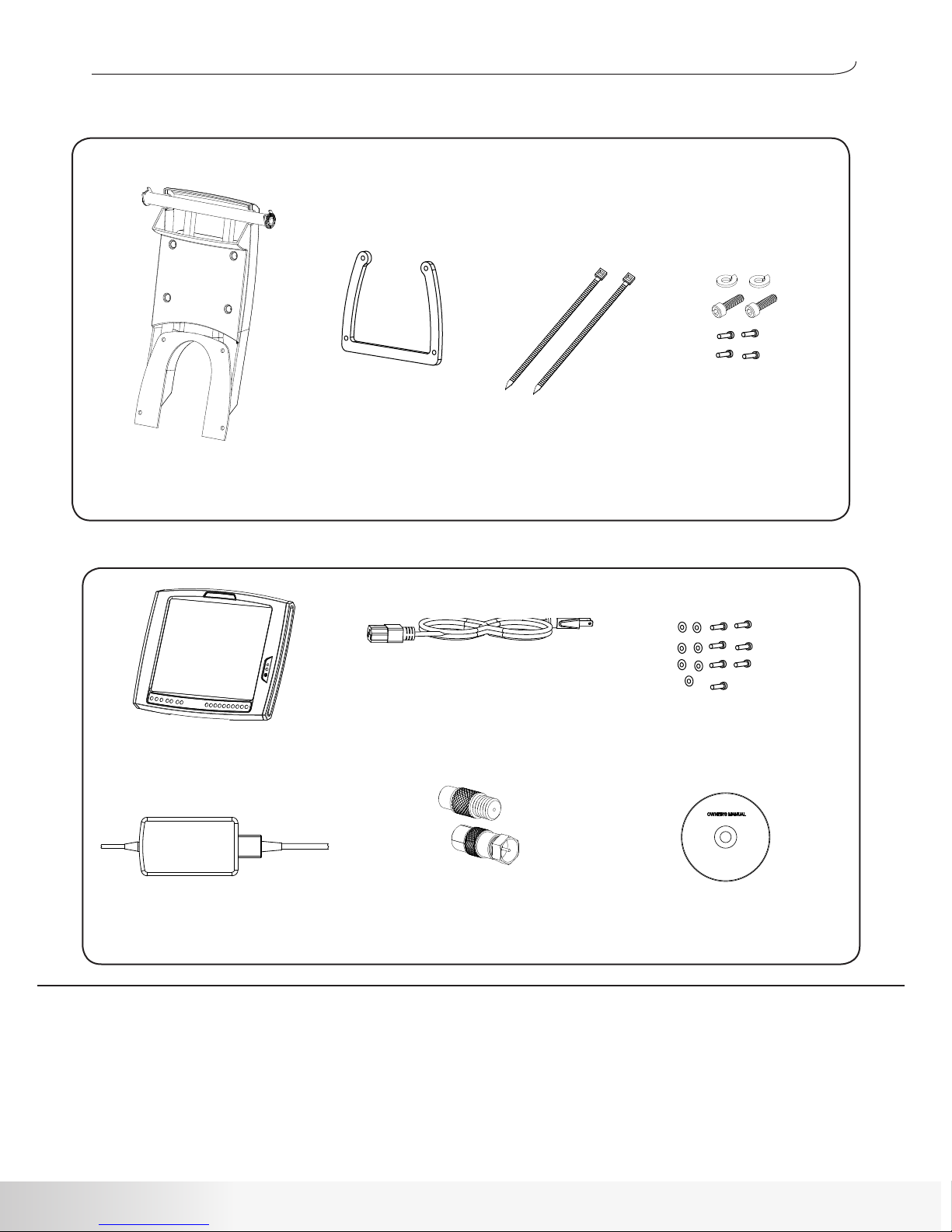
Box 1 Contents
LCD Bracket
Part # 000-8082
Box 2 Contents
LCD Monitor
Part # 001-1924 US (NTSC)
Part # 001-1992 (PAL)
Part # 002-3782 US (Digital)
Power Supply
Part # 000-8010
Part # 002-3787 (Digital)
Console Spacer
Part # 001-1894
Power Cord
Part # 001-1922 US
Part # 001-2015 Continental
Part # 001-2017 UK/Ireland
Part # 001-2019 Australia
International Coax
Adapter
Part # 001-1995
Wire Ties
Hardware Pack
Part # 001-1916
Hardware Kit
Part # 001-1938
Owners Manual CD
Part # 001-7167
Tools Needed:
• 3/16” Allen wrench
• 6mm Allen Wrench
• Wire Cutter
• Phillips Head Screwdriver
Product Specifications:
M-Series Bracket
Gross Weight: 8.0 lbs/ 3.63 kg
Net Weight: 4.75 lb/ 2.15 kg
Product Dimensions: 49cm (L) x 17cm (W) x 43cm (H)
19.3” (L) x 6.7” (W) x 16.9” (H)
Nautilus® LCD Installation
5
Page 6
Installation Procedure
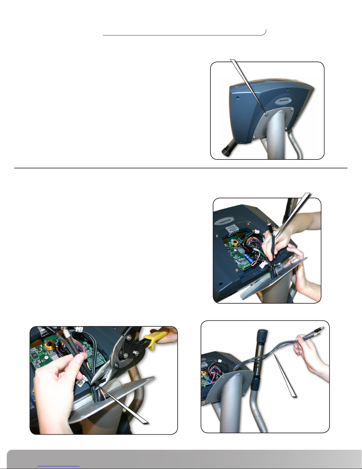
Step 1 Remove the Console
Phillips Head Screw
Tools Needed:
Phillips Head Screwdriver
1-1 Use a Phillips Head Screwdriver to remove the
four screws that secure the Console.
Step 2 Locate the LCD wires and remove the wire tie.
Tools Needed:
Wire cutter or similar
LCD Wires
2-1 Locate the LCD wires inside the mast. (Figure A)
2-2 Remove the wire tie. (Figure B)
2-3 Extend approximately 12” of the LCD wires.
(Figure C)
Figure A
Extend 12” of Wire
Figure B
6
Wire Tie
Figure C
Page 7

Installation Procedure
Step 3 Place Spacer between Console and Mast
3-1 Place the Spacer (Figure A) between the Console and
Mast as shown. (Figure B)
3-2 Allow the LCD wires to extend through the gap
between the Spacer and the Console, and over
top of the Mast. (Figure C)
3-3 Leave the Console in place on the Mast but
do not install the hardware at this time.
Spacer
Figure A
LCD Wires
Console
Mast
Spacer
Figure B
Step 4 Remove the Back Cover of the LCD Bracket
Tools Needed:
Phillips Head Screwdriver
Console
Spacer
Mast
Figure C
Bracket
Back Cover
4-1 Use a Phillips Head Screwdriver to
remove the four screws and washers
securing the Back Cover to the Bracket.
Phillips Head Screw
Nautilus® LCD Installation
7
Page 8

Installation Procedure
Step 5 Attach the LCD Bracket
Pass Wires through Bracket
Parts needed:
LCD Bracket
Four 1/4” x 1” Phillips Head Screws
Tools Needed:
Phillips Head Screwdriver
5-1 Pass the LCD wires through the Bracket between
the metal plate and the plastic cover as shown.
(Figure A)
5-2 Align the Bracket with the Console mounting
holes on the Mast. (Figure B)
5-3 Replace the original Console hardware with the
four 1/4” x 1” Phillips Screws provided.
5-4 Completely tighten the hardware. (Figure C)
Plastic Cover
LCD Wires
Metal Plate
Figure A
Mast
Figure B
1/4”x1” Phillips Screw
LCD wires
Figure C
8
Page 9

Installation Procedure
NOTE: To keep the LCD Wires in place, it is helpful to pass them through the
Bracket as shown.
Step 6 Prepare to install the LCD Monitor
Tools Needed:
Phillips Head Screwdriver
6-1 Use a Phillips Head Screwdriver to remove
the Back Cover of the LCD monitor. (Figure A)
Back Cover
Figure A
Nautilus® LCD Installation
9
Page 10

Installation Procedure
Step 7 Attach the LCD Monitor
Tools Needed:
6mm Allen wrench
7-1 Position the LCD Monitor on the Bracket (Figure A)
with the Metal Tabs resting between the upright
prongs discussed in Step 6. (Detail A)
7-2 Install the M10 Allen Bolts and Lock Washers.
(From Hardware Kit)
7-3 Position the LCD Monitor. (Figure B & C)
Note: The Monitor has a 30º range of
viewing angles. Position at your discretion (Figure B & C).
7-4 Completely tighten the M10 Allen Bolts.
LCD Monitor
Figure A
Prong
Bracket
Metal Tab
Figure B
30º Range
Detail A
30º Range
10
Figure C
Page 11

Installation Procedure
Step 8 Connect Wires to Monitor
The connections shown are for Pre Wired units with Coaxial and power connections only.
For alternative configurations please refer to the LCD Monitor owners manual.
IMPORTANT! You must wire tie the Power Wire to the LCD Bracket to avoid
accidental disconnection.
NOTE: If you are using the optional Wired Remote, attach the end
labeled LCD TV at this time. Refer to Wired Remote Installation
Manual for more information.
NOTE: International version
will require supplied
Coaxial Connection
Adapter.
Wire Tie
International Coaxial Adapters
Power
Power
Antenna
These connections are not used in this configuration
For alternative configurations please refer to the LCD Monitor owners manual.
Antenna
Antenna
Connections are REVERSED for the NV915 LCD Digital Monitor.
Power
Nautilus® LCD Installation
11
Page 12

Installation Procedure
Step 9 Replace the Back Covers
Tools Needed:
Phillips Head Screwdriver
9-1 Use the M4 Screws and Washers from the Hardware
Kit to replace the Back Cover of the Bracket (Figure A)
and the LCD Monitor. (Figure B)
NOTE: Use the two longer screws on the raised
portion of the LCD Monitor Back cover.
(Detail A)
Use longer
screws here
Bracket Back Cover
Figure A
Figure B
12
Detail A
Page 13

Commercial Bikes Installation Procedure
ATTENTION: After steps 1-9 of the M-Series installation manual, use this page to make
connections to EV916, E916, Commercial Bikes, and the future redesigns of the
stepper.
If you are installing the monitor on an elliptical unit, proceed to Step 10.
If you are installing the monitor on any product other than an elliptical,
installation is complete after making the connections shown below.
Secure the Power Brick to the Power Connector and the Coaxial Cable to the Coax Connector
on the Mounting Plate as shown.
TV Coax Connector
Power For Unit
Mounting Plate
TV Power Connector
Nautilus® LCD Installation
13
Page 14

Installation Procedure
ATTENTION: The following steps apply to pre-wired Commercial Ellipticals only.
For non pre-wired instructions, refer to the appropriate LCD wiring
manual for the unit.
Right Shroud
Step 10 Remove Right Shroud
Tools Needed:
Phillips Head Screwdriver
10-1 Use a Phillips Head Screwdriver to remove the
Right Shroud.
Step 11 Secure the Power “Brick” to the Frame
Tools Needed:
Two Wire Ties
11-1 Connect the Power Wire to the power connection on top of the Frame. (Figure A)
11-2 Secure the Power Brick to the Mast using two Wire Ties as shown. (Figure B)
Mast
Power Connection
Power Brick
Power Wire
Wire Tie
Figure A
14
Figure B
Page 15

Installation Procedure
Step 12 Route the LCD Wires
12-1 Connect the Coaxial Cable and route the LCD Wires over the top, behind and under the
Frame Junction as shown.
Coaxial Connection
Route Wires
Behind Frame Junction
Leveler Feet
Step 13 Replace Right Shroud
Tools Needed:
Phillips Head Screwdriver
13-1 Replace the Right Shroud removed in Step 10.
Note:
You may have to adjust the
leveler feet to allow enough
clearance for the LCD Wires.
Adjust the feet enough to
allow clearance without
crushing the wires under the
stabilizer.
Step 14 Connect LCD Wires
14-1 Make appropriate Coax and Power connections where LCD Wires exit the unit.
NOTE: International versions will require supplied Coaxial Connection adapter.
(Figure C)
Figure C
International Coaxial Adapters
Nautilus® LCD Installation
15
Page 16

Installation Procedure
Installation is complete. For specific instructions on setup and use of the
LCD Monitor please refer to the LCD Monitor Users Manual
16
Page 17

Quick Reference Guide
Power Light
Infrared (remote) Receiver
Headphone Jack
1
2
3
4 5
1
Power
2
Volume Down
3
Volume UP
4
Mute
5
Video Input Source (Video/S-Video, Antenna)
Channel Down
6
7
Channel Up
8
Numeric Channel Keys
6
7
8
For specific instructions on setup and use of the LCD Monitor please refer to the
LCD Monitor Users Manual.
Nautilus® LCD Installation
17
Page 18

IMPORTANT CONTACT NUMBERS
If you need assistance, please have both the serial number of your machine and the date of purchase available when you
contact the appropriate Nautilus office listed below.
OFFICES IN THE UNITED STATES:
E-mail: cstech@nautilus.com
• TECHNICAL/CUSTOMER SERVICE
Nautilus, Inc.
World Headquarters
16400 SE Nautilus Drive
Vancouver, Washington, USA 98683
Phone: 800-NAUTILUS (800-628-8458)
Fax: 877-686-6466
• CORPORATE HEADQUARTERS
Nautilus, Inc.
World Headquarters
16400 SE Nautilus Drive
Vancouver, Washington, USA 98683
Phone: 800-NAUTILUS (800-628-8458)
INTERNATIONAL OFFICES:
For technical assistance and a list of distributors in your area,
please call or fax one of the following numbers.
• INTERNATIONAL CUSTOMER SERVICE:
Nautilus International S.A.
Rue Jean Prouvé 6
1762 Givisiez / Switzerland
Tel: + 41-26-460-77-77
Fax: + 41-26-460-77-70
Email: technics@nautilus.com
INTERNATIONAL OFFICES:
• SWITZERLAND OFFICE
Nautilus Switzerland S.A.
Tel: + 41-26-460-77-66
Fax: + 41-26-460-77-60
• GERMANY and AUSTRIA OFFICE
Nautilus GmbH
Tel: +49-2204-610-27
Fax: +49-2204-628-90
• ITALY OFFICE
Nautilus Italy s.r.l.
Tel: +39-031-51-10-86
Fax: +39-031-34-24-97
• UNITED KINGDOM OFFICE
Nautilus UK Ltd.
Tel: +44-1908-267-345
Fax: +44-1908-267-346
• CHINA OFFICE
Nautilus Representative Office
Tel: +86-21-523-707-00
Fax: +86-21-523-707-09
18
18
Page 19

Be Strong.
™
For more information about our LCD TV Monitor or other Nautilus®
equipment , visit www.nautilusinc.com.
© 20 07 Naut ilus, Inc . All righ ts reser ved. Naut ilus, th e Nautil us logo, and B e Strong a re either r egiste red trade marks or tr ademarks o f Nautil us, Inc.
Naut ilus, Inc . World Head quarte rs, 164 00 SE Nau tilus Dr ive, Vancou ver, Washin gton, US A 986 83, 1- 800 -628 -84 58, w ww.Nau tilus. com.
All o ther mark s are eith er regist ered trad emarks or t rademar ks of their r especti ve compani es.
 Loading...