

Nautilus Be Strong Commercial R916 Assembly Manual
Be Strong.
®
Commercial Series Bike R916
003-3375-060309A
Rework Manual

Table of Contents
Products Affected and Requiring Work………………………………………………………3
Tools Required………………………………………………………………………………………..3
Parts………………………………………………………………………………………………………4
Parts List………………………………………………………………………………....................6
Hardware………………………………………………………………………………………………..7
Assembly………………………………………………………………………………………………..8
Software Upgrade………………………………………………………………………………….13
Flywheel Intermediate Hub Assembly, Belt and Pulley Replacement…………….16
Final Inspection……………………………………………………………………………………..23
Final Packaging……………………………………………………………………………………..25
Appendix............................……………………………………………………………………..34

Products Affected and Requiring Rework
R916 Recumbent Bike
Product SKU Made In Serial Numbers
Domestic 380002 Taiwan All
Domestic 380002 USA 38002071108001-38002081027017
International 380003 Taiwan All
International 380003 USA 38003080103001-38003081208036
Global 100154 Taiwan 1000154ACU0930001-100154ACU09030027
Tools Required
FISPs
Phillips head screw driver (#2 drive)s
Vice-gripss
Cloth towel/rags
15/16” socket and socket torque wrenchs
13mm socket and wrenchs
4, 5, 6 mm Metric Allen wrenchess
Snap ring pliers (for 25mm shaft)s
Rubber mallets
Bearing puller (for pulley removal)s
Adjustable Crescent wrench (for all nuts)s
6mm hex drive bit and torque wrench (may be same torque wrench as used with 15/16” socket)s
Cyanoacrylate adhesive (a.k.a.: CA, SuperGlue™, CrazyGlue™).s
3
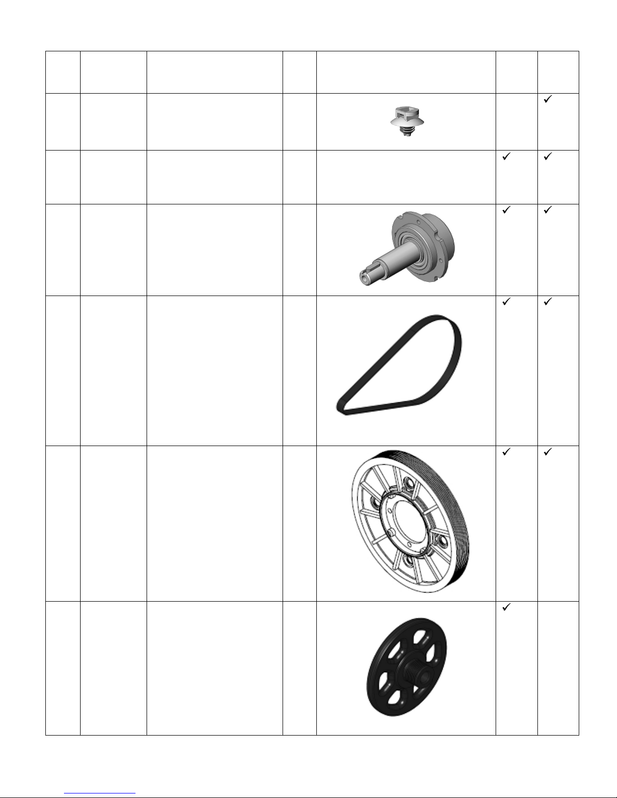
Item PN Description Qty R
Bike
Kit
1 002-6845 Shroud Spacer 1
2 41375-021 D51 Display Firmware 1 Firmware
U
Bike
Kit
3 002-6840 Intermediate Hub
Assembly
4 000-6432 Belt, Alternator, U/R916 1
5 000-6214 Assembly, Overmold,
Intermediate 8V Pulley
1
1
6 SM40329 Flywheel, Cast, 5300 1
4
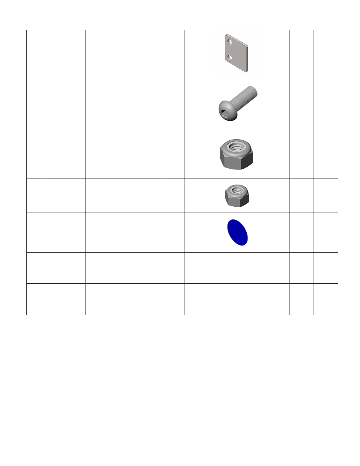
7
003-4716
Spacer, Seat, R916
4
9
8
902-4274
SCW-GHCS
M8x1.25x25 SS
1
9
9
902-4141
NUT NL M8-1.25 G2
BlkZ
3
9
10
902-4140
NUT NL M6-1.0 G2 Blk
Z
2
9
11
002-6858
Rework Sticker - Blue
1
9
12
003-3375060309
R916 Rework Manual
1
9
13
003-3376060
U916 Rework Manual
1
9
5

PARTS LIST / BOX CONTENTS
REF # DESCRIPTION QTY
A Console 1
B Console Mast 1
C Main Frame 1
D Seat Pad 1
E Handlebar 1
F Seat Back Assembly 1
G Right Mast Shroud 1
H Left Mast Shroud 1
I Right Seat Bottom 1
J Left Seat Bottom 1
K Hardware Pack (not shown) 1
PARTS LIST / BOX CONTENTS
G
F
A
D
E
B
C
I
H
J
6
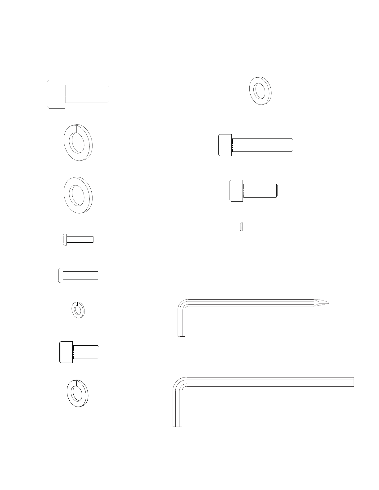
HARDWARE AND TOOL LIST
HARDWARE BAG - NOTE: ILLUSTRATIONS ARE NOT TO SCALE.
The Hardware Bag contains the following individual parts and tools.
Ref #1 Allen Head Bolt M10x25 Qty. 4
Ref #2 Spring Washer M10 Qty. 4
Ref #3 Flat Washer M10 Qty. 4
Ref #4 Phillips Head Screw #10-32 x 3/4” Qty. 10
Ref #5 Phillips Head Screw 1/4”x20 Qty. 4
Ref #9 Flat Washer M8 Qty. 12
Ref #10 Allen Head Bolt M8 x 40 Qty. 4
Ref #11 Allen Head Bolt M8x20 Qty. 4
Ref #12 Phillips Head Screw M4x12 Qty. 1
Ref #6 Spring Washer M6 Qty. 4
Ref #7 Allen Head Bolt M8x15 Qty. 4
Ref #8 Spring Washer M8 Qty. 12
Ref #13 6mm Allen Wrench / Phillips Screwdriver
Ref #14 8mm Allen Wrench
7

ASSEMBLY WITH SEAT CARRIAGE AND BRAKE
The following instructions provide direction in assembling the base unit for the Nautilus® Commercial Series Bike model
R916. All instructions in the manual are given with the orientation of sitting on the bike facing the console. The console is
the front, while the seat is the back.
Step 1:
Figure 1:
2
3
L
M
Locate the following for this step:
Parts:
B
1
s Console Mast (B)
Hardware:
s Ref #1 Allen Head Bolt M10x25 Qty. 4
s Ref #2 Spring Washer M10 Qty. 4
s Ref #3 Flat Washer M10 Qty. 4
N
Tools:
s 8mm Allen Wrench
1-1 Connect the attached long Wire Tie (L) to the
main and TV cables (M) and use it to pull the
cables up through the Mast (B). Make sure to
reposition the wire tie after the rework.
1-2 Align the Mast (B) with the four holes in the Main
Frame. (N)
1-3 Install and hand tighten the hardware.
8

Step 2:
ASSEMBLY GUIDE
Figure 3:
6
5
A
S
Q
O
Locate the following for this step:
Parts:
s Display Console (A)
Hardware:
s Ref #5 Phillips Head Screw 1/4”x20 Qty. 4
s Ref #6 Spring Washer M6 Qty. 4
P
Tools:
s Phillips Head Screwdriver
3-1 Plug the Main Console Wire (Q) into the large
Connector (J5 ) on the back of the Console.
(Figure 4)
3-2 The Right Heart Rate Wire (O) is labeled with an “R”.
Plug the Right Heart Rate Wire into the connector
labeled P1 on the back of the console. (Figure 4)
3-3 Plug the Left Heart Rate Wire (P) into the P2
connector. (Figure 4)
Figure 4:
P1
J5
P2
NOTE: If installing the optional LCD Monitor refer
to the NV915 installation manual at this
time. If not installing the LCD Monitor, tuck
the TV Cables (S) into the Mast.
3-4 Align the Console with the Mast, install two screws
only.
9
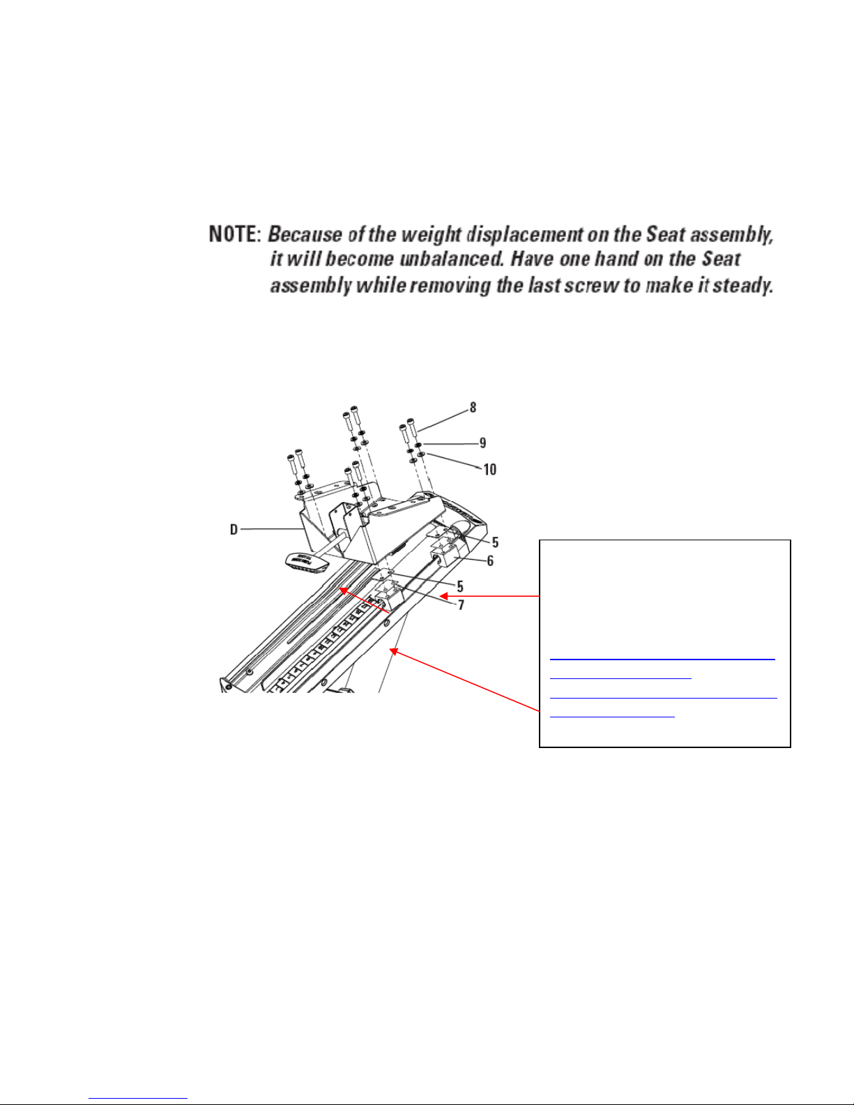
Seat Carriage Assembly Spacers and Brake
Assembly
STEP 3A: Adding seat spacers to seat carriage for
brake pad clearance.
Add four 003-4716 seat spacers
between the rail bushings and seat
carriage assembly, reattach seat
assembly to rail bushings. NOTE
detailed instructions are located at
N:\VW\CustomerCare\ProductSu
pport\Commercial\1Nautilus\Bikes\R916\BULLETIN
S\ServiceBulletins, # NLS R916
003.3209.SB.051509.B
10
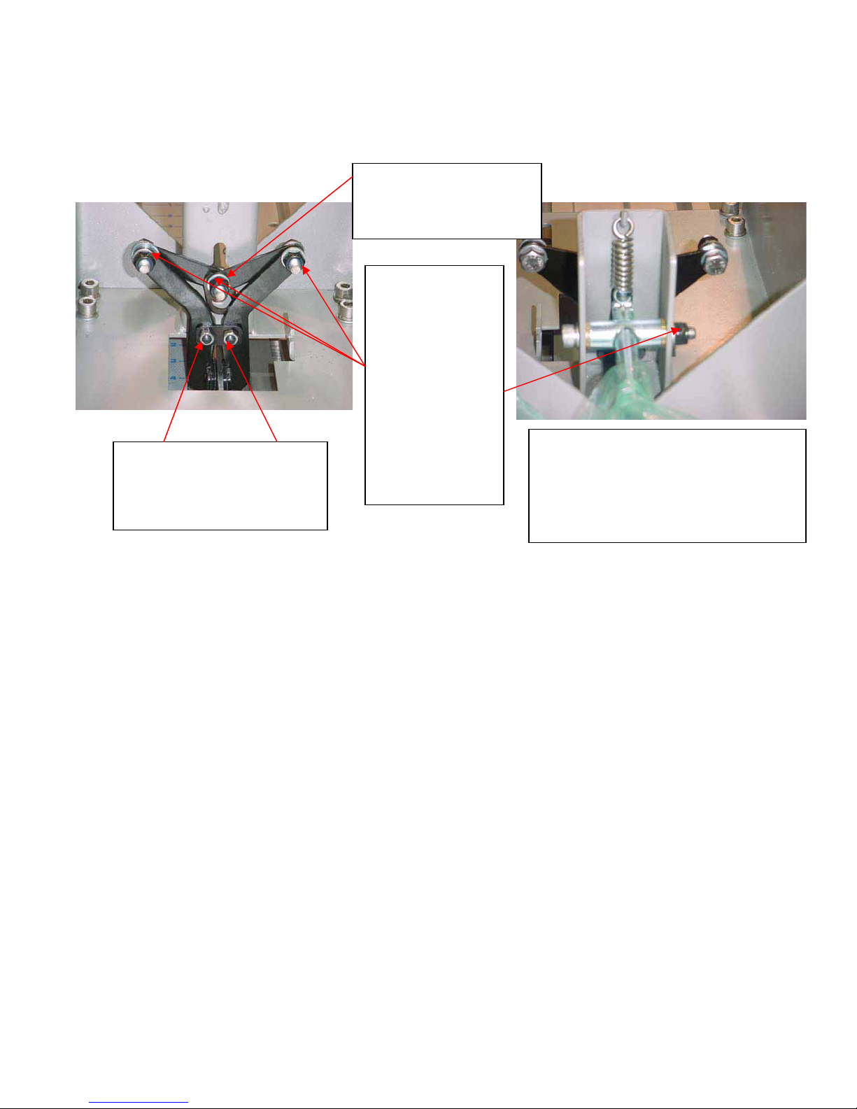
STEP 3B: Checking and replacing linkage nuts.
Check and replace if needed
with 003-3810 nylock nuts,
tools needed 10mm wrench
and a 4mm hex wrench
Note: Make sure one or both of the Brake Pads moves away from
the Brake Rail when the Handle is lifted. If they do not move,
loosen the three Nylock Nuts one-half turn until they do move.
Note B: Add some grease to the top of the button head to reduce
friction with adjoining metal plate.
Replace center Hex head
bolt with button head
screw 902-4274. Note B.
If the nuts
connecting the
linkage together
or not nylon lock
nuts they must
be replaced with
902-4141 nylock
nut three places.
Tools needed
two 13mm
wrenches and
6mm hex
Make sure you do not tighten the
Nut so much that it deforms the
Seat Carriage bracket. If it is too
tight, the Handle will not be able to
pivot.
STEP 3D: Reassemble. Replace all parts in reverse
order steps 15-14.
11
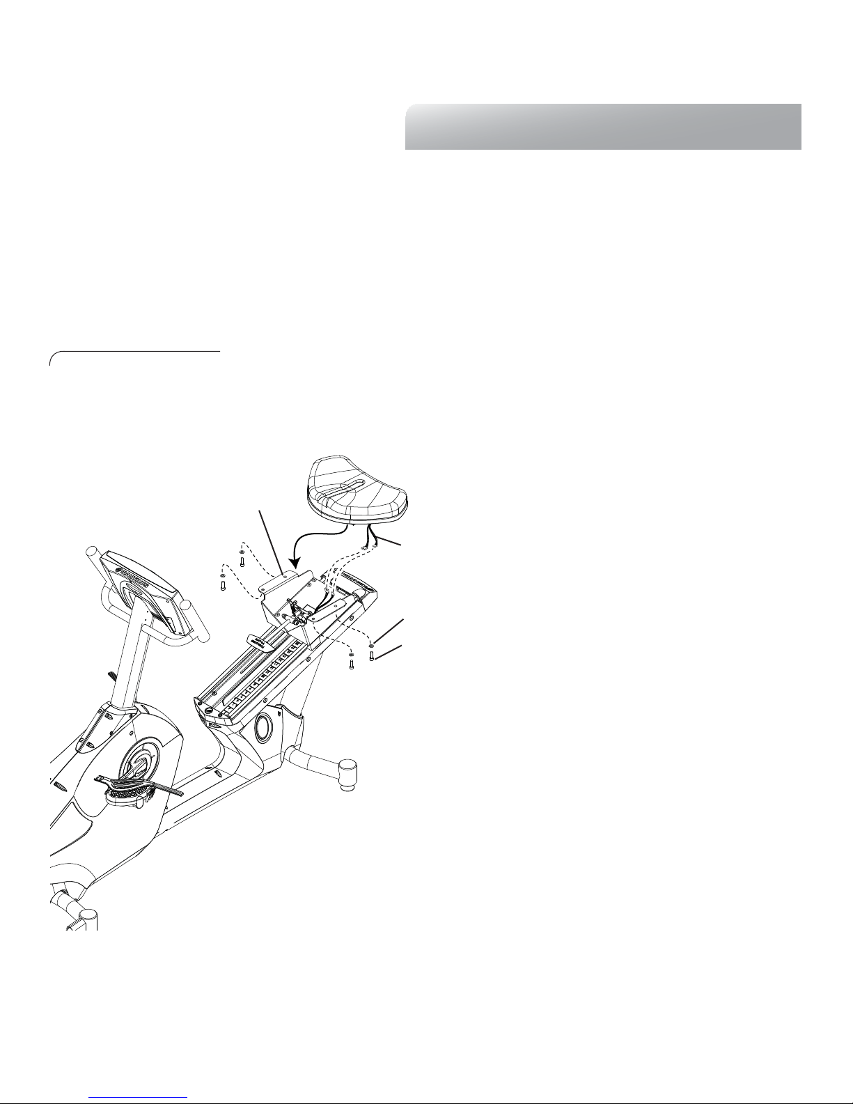
ASSEMBLY GUIDE
Step 4:
Locate the following for this step:
Parts:
s Seat Pad
Hardware:
s Ref #
11
Hex Head Bolt M8 x 20 Qty.
s Ref #9 S.S. Flat Washer M
8.5
Qty. 4
4
Figure 6:
Tools:
s
6
mm Hex Wrench
6-1 Carefully Align the Seat Pad with the
Seat Carriage (T).
6-2 Install and completely tighten the hardware.
T
Note: Use caution during this step as the Seat
U
Assembly is not yet secured to the Seat
Carriage. It is easier to perform this step if the
Carriage is positioned toward the top of the
9
11
range.
6-3 Connect the Heart Rate Cables (U) from the
Handlebars to the corresponding connectors
exiting the Seat Carriage (Figure 6).
6-4 Carefully place excess cable from Contact Heart
Rate cables in between the Seat and and the Seat
Carriage (Figure 6).
Note: To avoid damage to the Heart Rate Cables,
Do Not apply excessive force to the cables
while assembling connectors.
12
 Loading...