

Page 1
001–7332–090109B
Page 2

TableofContents
Specifications
ImportantSafetyInstructions
Features
LCDDisplayData
WirelessBikeSensorData
Operations
2
3
4
5
8
9
Specifications
ConsoleSpeedSensor
Length
Width
Thickness
Weight(console
w/sensor)
ShippingWeight
7.1"(18cm)
3"(7.7cm)
1.9"(4.8cm)
2.0lb(0.9kg)
2.8lb(1.3kg)
DevicePairing
Configuration/ServiceMode
ICClassSetup
Troubleshooting
Maintenance
Contacts
Length
Width
Thickness
11
13
25
26
28
31
3.3"(8.3cm)
2.5"(6.4cm)
1.5"(3.7cm)
PowerSensor
Length
Width
Thickness
Weight
ShippingWeight
DONOTdisposeofthisproductasrefuse.Thisproductistoberecycled.Forinformationon
thepropermethodofdisposal,contactaNautilusCustomerServiceRepresentative.Contact
informationisavailableintheContactssectioninthismanual.
Foradditionalinformationpleasevisit:
www.nautilus-international.net/recycle
PatentInformation
©2009Nautilus,Inc.,Allrightsreserved
™and®indicateatrademarkorregisteredtrademark.Nautilus,Inc.(www.nautilus.com)trademarksinclude
NAUTILUS®,BOWFLEX®,STAIRMASTER®,SCHWINN®andUNIVERSAL®andrespectivelogos.
Othertrademarksarethepropertyoftheirrespectiveowners.
ThisproductmaybecoveredbyUSandForeignPatentsandPatentsPending.
5.2"(13.3cm)
1.8"(4.5cm)
1.2"(3cm)
0.17lb(0.08kg)
0.22lb(0.1kg)
PowerRequirements
Console
SpeedSensor
PowerSensor
(2)CBatteries(LR14)
(1)CR2032Battery
(1)AABattery(LR6)
2
2 2
Page 3

ImportantSafetyInstructions
Indicatesapotentiallyhazardoussituationwhich,ifnotavoided,couldresultindeathorseriousinjury.
Beforeusingthisequipment,obeythefollowingwarnings:
ReadandunderstandthecompleteOwner’sManual.KeepOwner’sManualforfuturereference.
Readandunderstandallwarningsonthismachine.IfatanytimetheWarningstickersbecomeloose,unreadableor
dislodged,contactNautilusCustomerServiceforreplacementstickers.
•
• •
Childrenmustnotbeletonorneartothismachine.Movingpartsandotherfeaturesofthemachinecanbedangerousto
children
•
• •
Consultaphysicianbeforeyoustartanexerciseprogram.Stopexercisingifyoufeelpainortightnessinyourchest,become
shortofbreath,orfeelfaint.Contactyourdoctorbeforeyouusethemachineagain.Usethevaluescalculatedormeasured
bythemachine’scomputerforreferencepurposesonly.
•
• •
Ifyouhaveapacemakerorotherimplantedelectronicdevice,consultyourdoctorbeforeusingawirelesscheststrapor
othertelemetricheartratemonitor.
•
• •
Donotuseorputthemachineintoserviceuntilthemachinehasbeenfullyassembledandinspectedforcorrect
performanceinaccordancewiththeOwner’sManual.
•
• •
ReadandunderstandthecompleteOwner’sManualsuppliedwiththemachinebeforefirstuse.KeeptheOwner’sand
AssemblyManualsforfuturereference.
FCCCompliance
Changesormodificationstothisunitnotexpresslyapprovedbythepartyresponsibleforcompliancecouldvoidthe
user’sauthoritytooperatetheequipment.
Note:ThisdevicecomplieswithPart15oftheFCCRules.Operationissubjecttothefollowingtwoconditions:
(1)thisdevicemaynotcauseharmfulinterference,and(2)thisdevicemustacceptanyinterferencereceived,
includinginterferencethatmaycauseundesiredoperation.Theselimitsaredesignedtoprovidereasonable
protectionagainstharmfulinterferenceinaresidentialinstallation.Thisequipmentgeneratesusesandcan
radiateradiofrequencyenergyand,ifnotinstalledandusedinaccordancewiththeinstructions,maycause
harmfulinterferencetoradiocommunications.However,thereisnoguaranteethatinterferencewillnotoccur
inaparticularinstallation.Ifthisequipmentdoescauseharmfulinterferencetoradioortelevisionreception,
whichcanbedeterminedbyturningtheequipmentoffandon,theuserisencouragedtotrytocorrectthe
interferencebyoneormoreofthefollowingmeasures:
•
• •
Reorientorrelocatethereceivingantenna.
•
• •
Increasetheseparationbetweentheequipmentandreceiver.
•
• •
Consultthedealeroranexperiencedradio/TVtechnicianforhelp.
3
3 3
Page 4
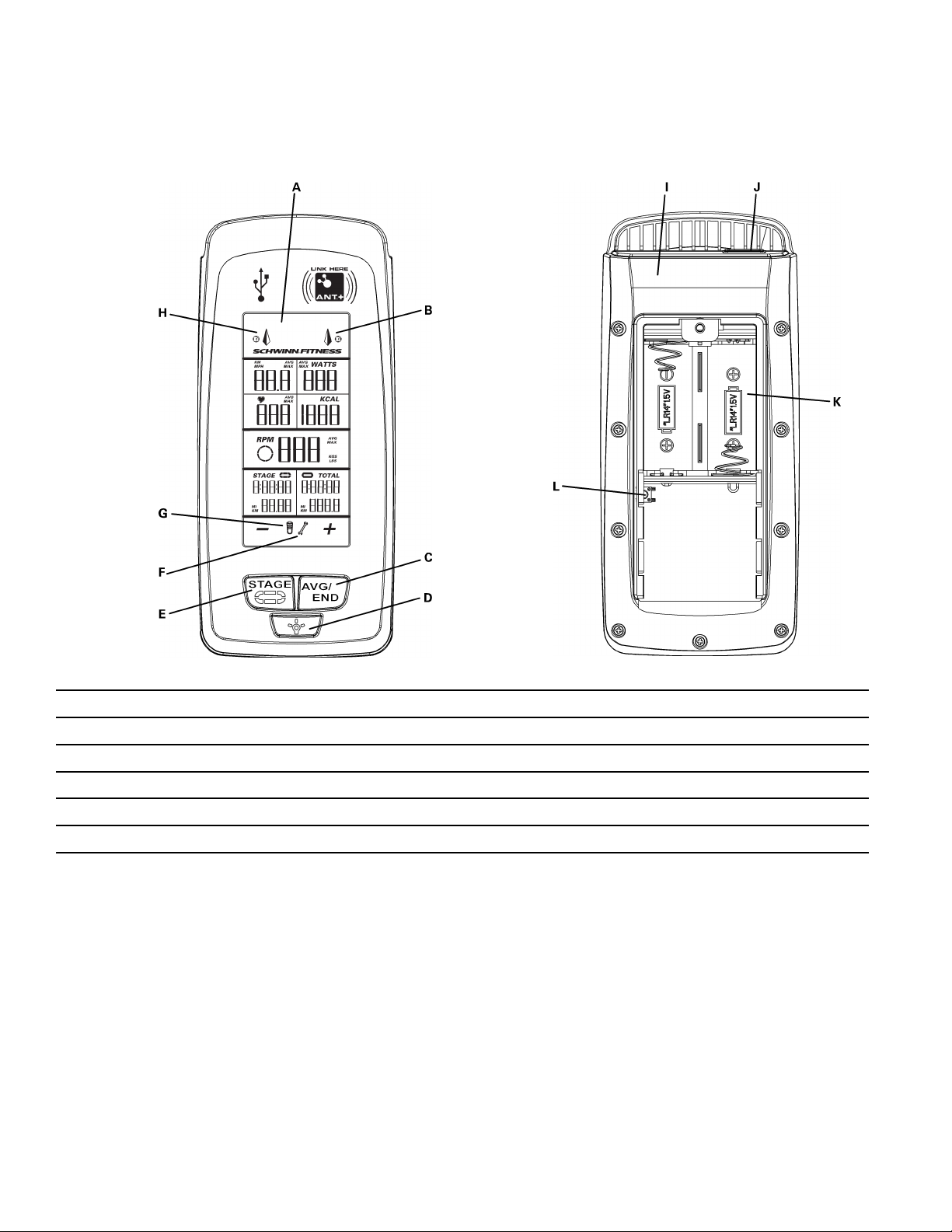
Features
FrontBack
A
BacklitLCDDisplayG
BAnt+LinkingIndicatorH
C
AVG/ENDButton(+)
DBacklightButtonJ
E
STAGEButton(–)
FMaintenanceAlertLAnt+PairingButton
BatteryLevel
USBInterfaceIndicator
IAnt+Transmitter
USBPort
KBatteryBay
LCD
Themulti-function,backlitLCDshowsyourworkoutmeasurements(duringtheworkout),results,usersetupdataandconsole
diagnostics.
Toturnonthebacklight,pushtheBacklightbutton.Thebacklightturnsoffafter7secondstoconservethebatteries.
HeartRateMonitor
Theconsolegetsheartratedatafromtheheartratemonitor(HRM)tocalculateworkoutdata,suchastheCaloriesburned.
Ant+Sport2.4GHzWireless
TheAnt+Sport2.4GHzWirelessHeartRateMonitor(HRM)sendsheartratedatatotheconsoleafterproximitylinkingoccurs
duringUserSetup.TheconsolecanreadtheHRMdatatoadistanceof118"(3m)duringWorkoutMode.
IfyouhaveapairedAnt+SportWatchandAnt+HRM,theconsolelinkswiththesportwatchandreadstheheartratedatafromit.
4
4 4
Page 5
StandardEM5kHzPulse
TheconsoleusestheEM(electromagnetic)5kHzpulsewirelessprotocoltoreadheartratedatafromstandardheartratemonitors
(HRMs),suchasaPolar®transmittercheststrap.
WorkoutDataStorage
Theconsolesendsworkoutdatatotheuser’sdatastoragedevice—forexample,aUSBflashmemorydeviceorasportwatch.The
consolecanalsogetuserdatafromanAnt+sportwatchandusethedatatocalculateworkoutresults.
Ant+SportWatch
TheAnt+SportWatchsharesuserdatawiththeconsoleafterproximitylinkingoccursduringUserSetup.InUserSetupModethe
Ant+Sportwatchsendsdata(includinguserweight)totheconsole.DuringWorkoutModetheconsolesendsworkoutdatatothe
Ant+SportWatch.Whenproximitylinkingiscomplete,thewatchandconsolecansendandreaddataupto118"(3m).
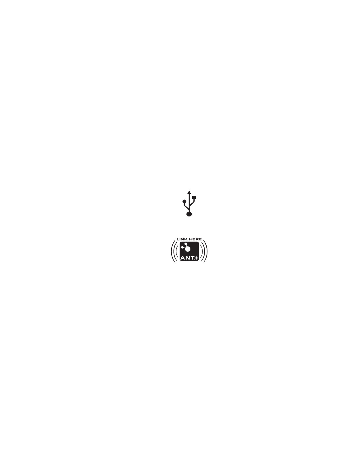
USBInterface/DataStorage
TheconsolecanuploadworkoutdatatoaUSBdatastoragedeviceiftheUSBportontheconsoleisenabled.ToenabletheUSB
port,gototheServiceModemenu.YoucanconnecttheUSBstoragedevicetotheconsoleduringUserSetuporafterthe
workoutends.
DuringWorkoutModetheconsolesendstheseworkoutdatatotheUSBdevice:
•
• •
Workout(total)—Time,Distance,andaverageandmaximumSpeed,Watts,HRandRPM.
•
• •
WorkoutStages—Time,Distance,andmaximumSpeed,Watts,HRandRPM.
IfyouconnecttheUSBdeviceaftertheworkoutends,theconsoleonlysendstheTotalSummarydatatotheUSBdevice.
TheUSBportalsogivesaccesstotheServiceTechniciantoexportconsolesystemdatatoaUSBstoragedeviceandtoupdate
theconsolefirmware.
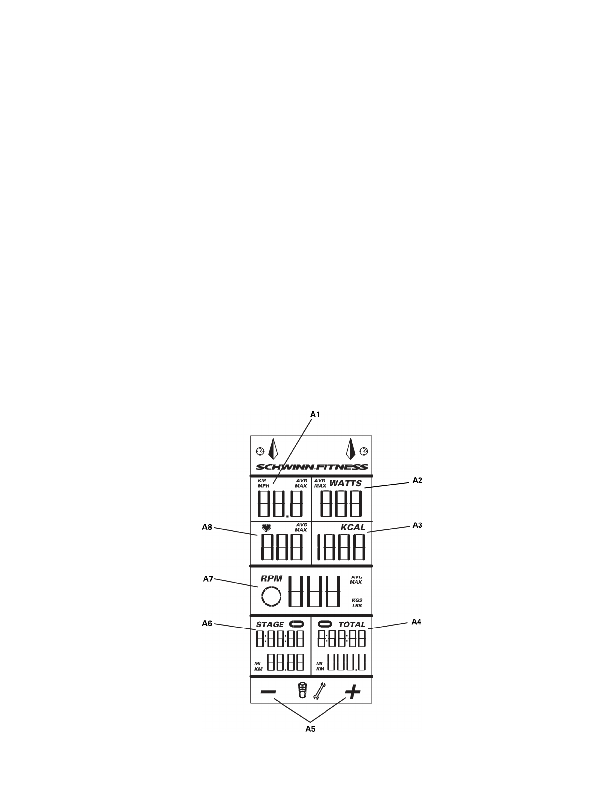
LCDDisplayData
5
5 5
Page 6

A1
KM/MPH(Speed)
A5
+/–(WeightInput)
A2
A3
A4
WATTS(Power)
KCAL(Calories)
TOTALTimeandDistance
Note:
IfyouneedtochangethemeasurementunitstoEnglishImperialormetric,refertotheUserSetup
sectionofthismanual..
A6
A7
A8HeartRate
STAGETimeandDistance
RPM(Cadence)
Speed
TheSpeeddisplayfieldshowstheestimatedspeedofthebikeinkilometersperhour(KM/H)ormilesperhour(MPH).
ToviewtheaveragespeedduringWorkoutMode,taptheAVG/ENDbutton.
Watts
TheWATTSdisplayfieldshowsthepowerthatyouareproducingatthecurrentresistancelevel(1horsepower=746watts).
WATTSdataonlyshowsifthereisapowersensorinstalledonthebike.
ToseetheaveragewattsduringWorkoutMode,taptheAVG/ENDbutton.
HeartRate
TheHeartRatedisplayfieldshowstheheartrateinbeatsperminute(BPM)fromtheheartratemonitor(HRM).Thehearticon
flasheswhentheconsolereceiversensestheHRMsignal.IftheconsolereceiverdoesnotsensetheHRM,thecenterofthe
hearticonisonsolid.
IftheconsolereceiversensesanAnt+HRMsignal,thereisanoutlinearoundthehearticon.Theoutlinedoesnotflash.IftheHRM
signalisastandardEM5kHzpulsesignal,thereisnotanoutlinearoundtheicon.
ToseeyouraverageheartrateduringWorkoutMode,taptheAVG/ENDbutton.
Consultaphysicianbeforeyoustartanexerciseprogram.Stopexercisingifyoufeelpainortightnessinyourchest,
becomeshortofbreath,orfeelfaint.Contactyourdoctorbeforeyouusethemachineagain.Usethevaluescalculatedor
measuredbythemachine’scomputerforreferencepurposesonly.
Calories
TheCaloriesdisplayfieldshowstheestimatedcaloriesthatyouhaveburnedduringtheexercise.
IfthebikedoesnothaveaPowerSensor,theconsolecalculatesthecaloriesfromtheheartratedatafromtheHRM.
RPM
TheRPMdisplayfieldshowsthecurrentpedalrevolutionsperminute(RPM).
ToseetheaverageRPMduringWorkoutMode,taptheAVG/ENDbutton.
ForbikesthatdonothaveaPowerSensorinstalled,theRPMfieldisalsotheuserweightinputfieldduringUserSetupMode.The
consolewillshowerrormessagesinthisfieldifanerroroccurs.
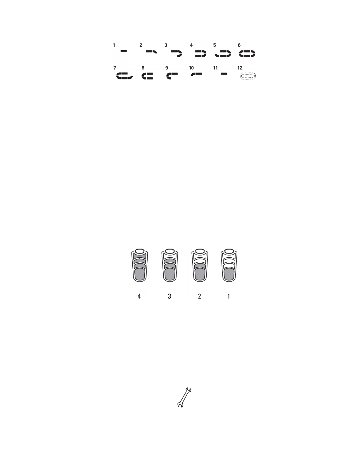
WorkoutStage
TheSTAGEdisplayfieldshowsthetimeanddistanceinthecurrentStageoftheworkout.Thedisplayvaluesstartatzeroand
countforwarduntiltheendoftheStage.AteachStageintheworkout,theStageiconshowstheStagenumberwiththenumberof
segmentsthatareon:
6
6 6
Page 7
WorkoutTotals
TheTOTALdisplayfieldshowsthetotaltimeanddistanceresultsattheendoftheworkout.TheTotaliconislitduringWorkoutMode.
LCD+and–Icons
The+and–(plusandminus)iconsontheLCDflashtoprompttheusertoentertheirweightduringUserSetupMode.The
iconsturnoffwhennotinuse.
Keypad
Themulti-functionkeypadletsyousettheconsolemeasurementsforyourworkout,seeandupdateyourworkoutdata,and
examinetheconsolediagnosticmessages.TapanybuttontoactivatetheconsolefromSleepMode.TheOperationssectionof
thismanualgivestheproceduresforusingthebuttonsineachOperationsmode.TheBacklightbuttonsetsyourselectionsin
UserSetupModeandServiceMode.
Alerts
TheConsoleiconsandLCDdisplaymessagesshowthestatusoftheconsoleandsensoroperations.
BatteryLevel
TheBatteryLeveliconshowstheoverallbatterylevelfortheconsole-sensorsystem.All4segmentsoftheiconareonwhen
thebatterylevelishigh.Whenthebatterylevelislow,onlythebottomsegmentison.Thebottomsegmentflasheswhenbattery
levelisverylow.
Ifthesystembatterylevelislow,gototheServiceModemenu.UsetheAPmenuoptiontoseethelevelsoftheconsole
andsensorbatteries.
Ifthebatterylevelistoolowtocontinueoperation,theconsoledisplayflashesthemessage“LObatt”andtheconsolegoesinto
SleepMode.Ifthisoccursduringaworkout,theworkoutstopsandtheconsoledisplayshowstheworkoutresultsfor10seconds.
Thenthe“LObatt”messageshowsandtheconsolegoesintoSleepMode.
MaintenanceAlert
TheMaintenanceAlerticonblinkswhenamaintenanceconditionoccurs.LookforerrormessagesontheLCDdisplay.Refer
totheTroubleshootingsectionofthismanual.TogototheServiceModemenu,pushtheAVG/ENDandSTAGEbuttonsand
holdfor5seconds.
7
7 7
Page 8
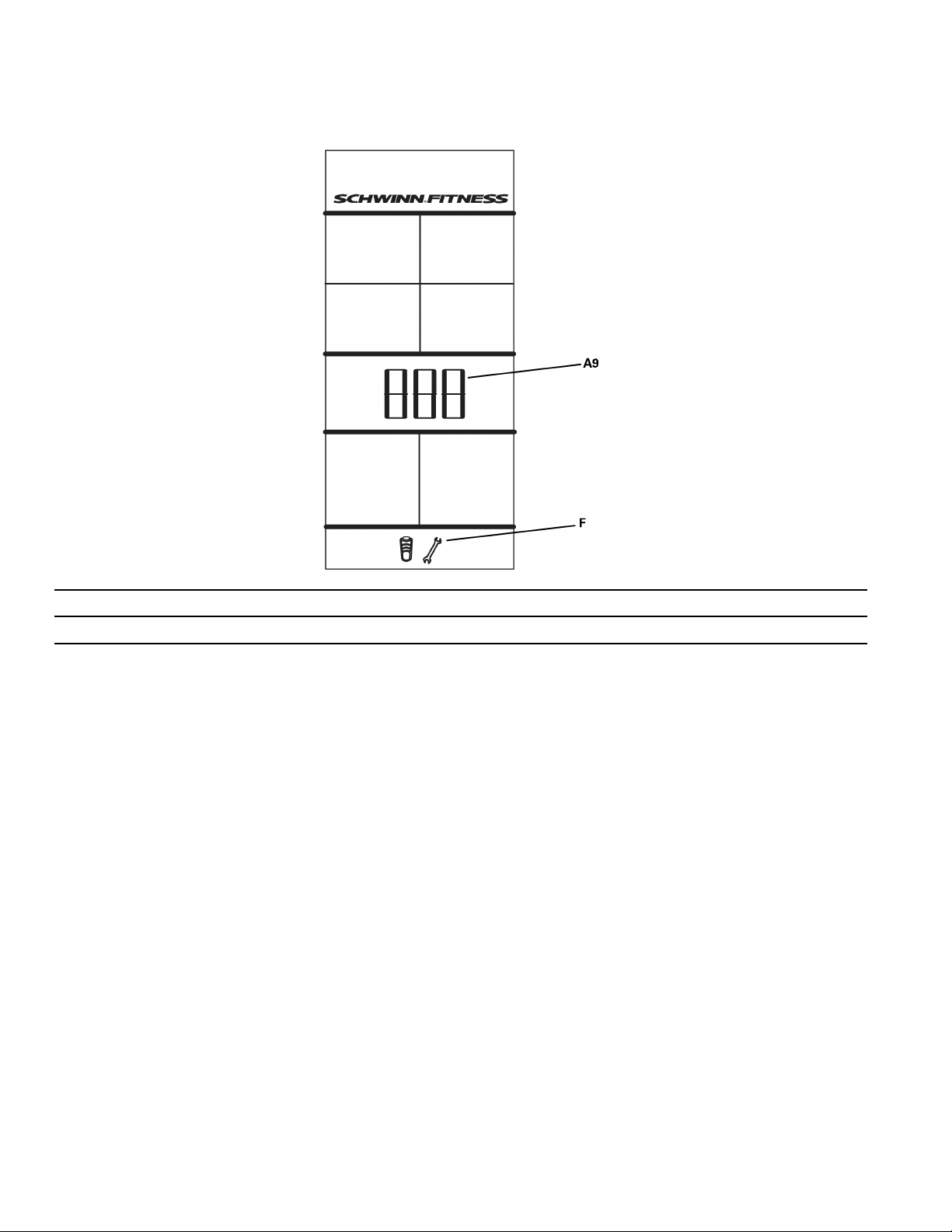
Errors
Errormessagestellyouwhenthereisaprobleminthebike’soperation:
A9ErrorMessage
F
RefertotheTroubleshootingsectionofthismanual.TogototheServiceModemenu,pushtheAVG/ENDandSTAGEbuttons
andholdfor5seconds.TheLCDdisplayisdifferentforErrorsthatoccurduringanon-ServiceMode(ex:WorkoutMode)and
ErrorsduringServiceMode.
MaintenanceAlerticonflashes
WirelessBikeSensorData
Theconsolegetsbikeoperationdatafromthebike’ssensorsandusesthedatatocalculateworkoutresults.Theconsoleand
wirelesssensorscantransmitdataaftertheDevicePairingprocesssetsuptheirwirelessconnection.TheConfiguration/Service
ModesectionofthismanualgivestheDevicePairingprocedure.ItiseasiesttosetupDevicePairingbeforeyouinitiallyinstall
theconsoleandsensorsonthebike.
BikeSpeedSensor
TheSchwinn®MPower™Consolecomeswithaspeedsensorforthebike.Thespeedsensortransmitsdatafromtheflywheel
totheconsoleduringtheworkout.
RefertotheSchwinn®MPower™ConsoleInstallationGuidefortheproceduretoinstallthespeedsensorontheSchwinn
A.C.™bike.
PowerSensor
TheMPower™PowersensorisanoptionalupgradeforaSchwinnA.C.™bikewithaSchwinn®MPower™Console.Thepower
sensortransmitsdatafromtheBrakeresistancemechanismtotheconsoleduringtheworkout.
RefertotheSchwinn®MPower™PowerUpgradeInstallationGuidefortheproceduretoinstallthepowersensoronthe
SchwinnA.C.™bike.
8
8 8
Page 9
Operations
SleepMode
TheconsoleautomaticallygoesintoSleepModetoconservethebattery:
•
• •
ifthereisnoactivityfor45secondsafterUserSetup.
•
• •
afterDisplayResults.
•
• •
ifWorkoutModepausesandthereisnoactivityfor5minutes.
PushanybuttontoactivatetheconsolefromSleepMode.
UserSetup
WhentheconsoleisinSleepMode,pushanybuttontogotoUserSetupmode.
DuringUserSetupModetheconsolecollectsthenecessaryuserdatatocalculateandrecordyourworkoutdata.Proximitylinking
totheuser’sHRMorAnt+watchoccurswhileinUserSetup.
IftheconsoledoesnotfindaUSBstoragedeviceorAnt+watch,thearrowiconsontheconsoleblink.Usetheappropriate
instructionforyourmonitoringequipment.
•
• •
USBstoragedevice—installthedeviceintheUSBport.Whentheconsolesensesthedevice,theUSBarrowindicator
stayson.
•
• •
Ant+watch—linktotheconsole.Movethewatchto2–4"(5–10cm)orlessfromtheAnt+LinkHerelogoontheconsoleand
holditthereuntilthearrowstayson.TheAnt+arrowandwatchindicatorscomeonwhenproximitylinkingiscomplete.
•
• •
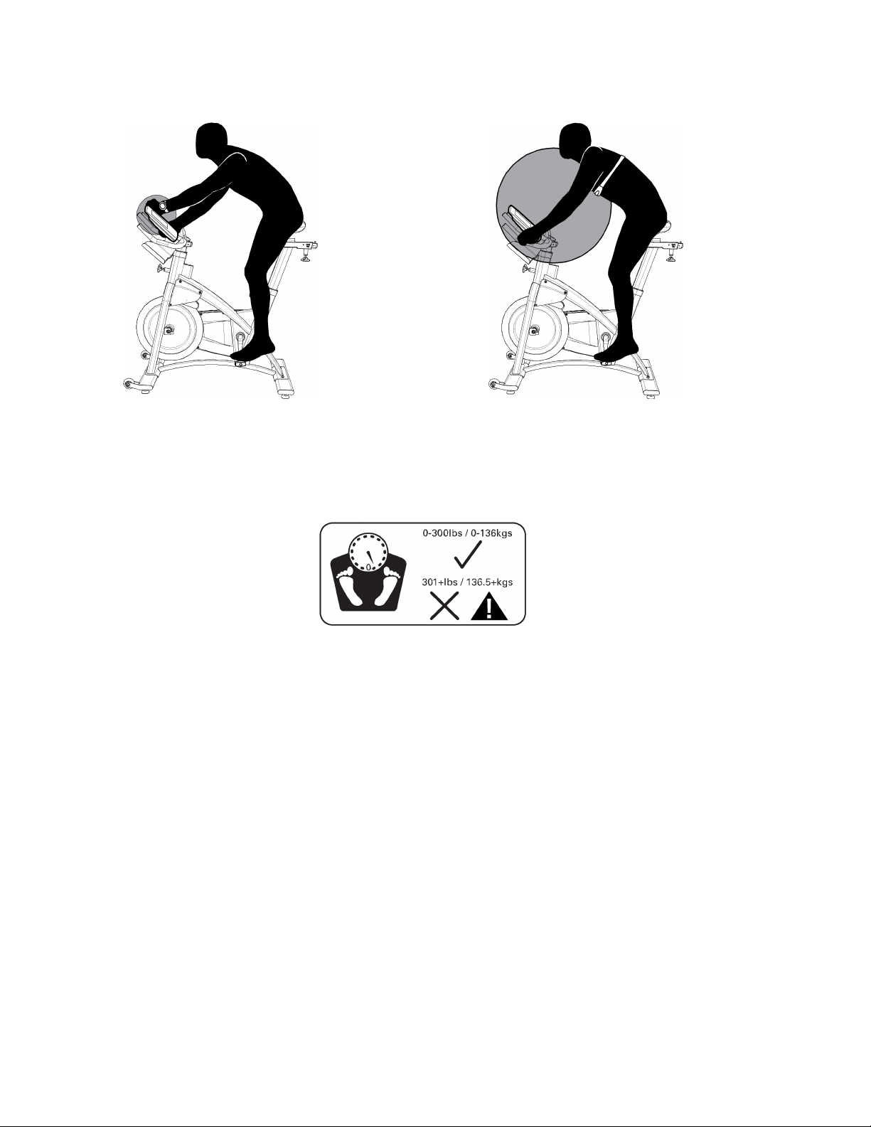
Ant+HRM—linktotheconsole.LeanintotheconsolesothattheHRMis7.5–31"(20–80cm)fromtheAnt+LinkHerelogo,
untilthearrowstayson.TheAnt+arrowindicatorcomesonwhenproximitylinkingiscomplete.IftheAnt+indicatorisnot
on,theconsoleusesEM5kHzsignaltocalculateHRM.
Note:
IfyouhaveanAnt+SportWatchandpairedAnt+HRM,itisonlynecessaryforthetheconsoletolink
withthesportwatch.However,ifyouhaveanAnt+SportWatchandEM5kHzHRM,theconsolelinksto
thewatchandtheHRM.
9
9 9
Page 10
Ant+
Watch
ForbikesthatdonothaveaPowerSensorinstalled,userweightdataisnecessarytocalculatetheCaloriesduringtheworkout.If
theconsoledoesnotgettheweightdatafromadevice,youmustmanuallysettheweightvalue.The+and–iconsontheLCDflash,
andtheRPMfielddisplays170lbs.(80kg).UsetheSTAGE(–)andAVG/END(+)buttonstoadjustthenumbertoyourweight.
HRM
Note:TochangetheweightunitstoEnglishImperialormetric:
•
• •
PushtheSTAGEandAVG/ENDbuttonsfor5secondstogotoServiceMode.
•
• •
TaptheAVG/ENDbuttonuntilyouseetheUNmenuoption,andpushtheBacklightbutton.
•
• •
PushtheSTAGEorAVG/ENDbuttontoseetheUNmenuoptions—UN0(metric)andUN1
(Imperial).PushtheBacklightbuttontosettheunitsmeasure.
•
• •
TheconsolegoesbacktotheServiceModemenuandtheUNmenuoptionappears.Tapthe
STAGEorAVG/ENDbuttonuntilyouseethe“––”(exit)optionintheServiceMenu.
•
• •
PushtheBacklightbuttontogobacktoUserSetupMode.
PushtheBacklightbuttontorecordyourweight.
DuringUserSetup(whileRPMislessthan80),itispossibletolosetheproximitylinkingtoanAnt+watchorAnt+HRMifyoumove
toofarawayfromtheConsole.IfthisoccursfortheAnt+watch,theAnt+watchindicatorflashes.IfthisoccursfortheAnt+HRM,
theHRdisplayfieldshows0(zero).Youmustdotheproximitylinkingprocedureagain.
IfWorkoutModedoesnotstartin45seconds,thereisnokeypadactivityandRPMislessthan5,theconsolereturnstoSleepMode.
WorkoutMode
AfterUserSetupiscomplete,startpedalingthebike.WhentheCadenceRPMincreasesto80RPMormore,theconsolegoesinto
WorkoutMode.TheWorkoutSTAGEandTOTALiconscomeonandtheworkoutmeasurementsstart.
10
10 10
Page 11

Note:
TaptheAVG/ENDbuttontoseeyouraveragedatavalues(AVG).Theaveragevaluesshowfor5seconds.Togobacktocurrent
measurementsmorequickly,taptheAVG/ENDbuttonagain.
WhentheCadencedecreasestolessthan5RPMfor3secondsormore,theconsolepausesandtheLCDDisplayshowsthelast
workoutdatavalues.Ifyoustaypausedformorethan5minutes,theworkoutstopsandtheconsolegoestoDisplayResultsmode.
TosettheSTAGEtimeandSTAGEdistancebacktozeroforanewstageintheworkout,taptheSTAGEbutton.TheTOTALtimeand
TOTALdistancecontinuethetotalmeasurementfortheworkout.
Toendtheworkout,pushtheAVG/ENDbuttonandholdfor3seconds.TheconsolegoestoDisplayResultsmode.
IfproximitylinkingwasnotcompleteinUserSetup,theconsolecanstilllinkwiththeAnt+sportwatchand
HRMduringthefirst30secondsofWorkoutMode.
DisplayResults
TostoptheworkoutandgotoDisplayResultsMode,pushtheAVG/ENDbuttonandholditfor3secondsorlonger.Theconsole
showstotalCalories,TOTALtimeanddistance,andtheMaxandAveragevaluesforSpeed,Watts,HeartRateandRPM.TheMax
valuesshowfirstfor5seconds.TaptheAVG/ENDbuttontochangebetweenMaxandAveragevalues.After1minute,the
consolesetsthevaluesbacktozeroandgoesintoSleepMode.
PushtheAVG/ENDbuttonandholdfor3secondstostopDisplayResultsModeandgotoSleepMode.
DevicePairing
SetupDevicePairingfortheConsole,theSpeedSensorandthePowerSensor(ifapplicable)beforeyouinstallthemonthebike.
IfyouaddthePowerSensorupgradetoabikethatalreadyhastheConsoleandSpeedSensorinstalled,itisnecessarytoset
upDevicePairingagainfortheconsoleandthe2sensors.Itisnecessarytoremovetheconsoleandsensorfromthebikefor
accesstothepairingbuttons.
1.Makesurethebatteriesareintheconsole(K1)andthesensors(K2andK3,ifapplicable).
Console SpeedSensor
11
11 11
Page 12

Power
Sensor
2.PushtheSTAGEandAVG/ENDbuttonsfor5secondstogotoServiceMode.
3.TaptheAVG/ENDbuttonuntilyouseetheP––menuoption,andpushtheBacklightbutton.
4.PushtheSTAGEorAVG/ENDbuttontoseetheP––submenuoptions—PE0(notpowerenabled)andPE1(powerenabled).
•
• •
IfyouhaveaPowerSensor,gotothePE1optionandpushtheBacklightbuttontosetPE(powerenabled).
•
• •
IfthereisnoPowerSensor,gotothePE0optionandpushtheBacklightbuttontosetNPE(notpowerenabled).
5.TheconsolegoesbacktotheServiceModemenuandtheP––menuoptionappears.
6.Makesurethattheswitch(U)ontheSpeedSensorissettoS(speed).
7.PushthepairingbuttonsontheConsole(L1),theSpeedSensor(L2)andthePowerSensor(L3),ifapplicable.
8.TheconsoledisplayshowsPPPandthetimedisplaycountsdownfrom0:35(seconds).
12
12 12
Page 13

A12ErrorMessageA45
ProcessStatus(SpeedSensor)
A42
A43PairingA47
A44
9.TheProcessStatusindicator(s)ontheconsoledisplayshows“–––”whilethePairingoperationcontinues.
10.WhenthePairingprocedureiscompleted,pushtheBacklightbuttontogobacktotheServiceMenu.
11.TaptheSTAGEorAVG/ENDbuttonuntilyouseethe“–––”(exit)optionintheServiceMenu,andpushtheBacklightbutton.
12.Installtheconsoleandsensorsonthebike.RefertotheMPower™installationguides.
PowerConfiguration(PE/NPE)
CountdownTimer(SpeedSensor)
IfPairingiscompletedsatisfactorily,theconsoledisplayshowsPASS.
ThecircuitboardinsidethePowerSensorcoverhas2colorLEDs—1greenand1red.The2LEDscomeonduring
thePairingoperation.Whiletheoperationcontinuessatisfactorily,thegreenLEDison.WhenPairingiscompleted
satisfactorily,bothLEDsturnoff.IfthePairingoperationisnotcompletedsatisfactorily,onlytheredLEDstayson.
IfthePairingoperationisnotcompletedsatisfactorily,theconsoledisplayshowsFAIL.Pushthepairingbuttononthe
console(L1).ThendotheDevicePairingprocedureagain.
IfthePairingoperationwasnotcompletedsatisfactorily,theconsoledisplayshowstheP––menuoptionagain.Pushthe
pairingbuttonontheconsole(L1).ThendotheDevicePairingprocedureagain.
A46
A48PairingIndicator
ProcessStatus(PowerSensor)
CountdownTimer(PowerSensor)
DevicePairingforMultipleBikes
ForSchwinnA.C.™bikeswithMPower™Consolesinagroupsetting,makesuretosetupDevicePairingforonlyonebikeatatime
topreventcrosstalkbetweenthedevicesondifferentbikes.
NOTICE:
Recommendation:YoucanputnumberlabelsonthebikesandhandlebarstomakesurethattheDevicePairingstays
Whenyouremovethehandlebars(withconsole)tocleanthem,makesurethatyouinstallthemagainonthe
samebiketokeeptheDevicePairingcorrect.Ifyouinstallthehandlebarsandconsoleonadifferentbike,the
consoledoesnotreaddatafromthecorrectsensors.
correct.
Configuration/ServiceMode
TheServiceModemenuletsServiceTechnicianssetthebikeconfigurations,seemaintenancedata,docalibrationsandupgrade
theconsolefirmware.AccesstoServiceModeisavailablewhentheconsoleisinUserSetupMode:
•
• •
PushtheSTAGEandAVG/ENDbuttonsfor5secondstogotoServiceMode.
•
• •
TaptheAVG/ENDorSTAGEbuttontolookattheServiceModemenuoptions.
•
• •
PushtheBacklightbuttontomakeyourselectionandgotothesubmenuoptions.
•
• •
TaptheAVG/ENDorSTAGEbuttontolookatthesubmenuoptions.
•
• •
PushtheBacklightbuttontosetthecorrectoption.
•
• •
TheconsolegoesbacktotheServiceModemenuandthecurrentmenuoptionappears.
Note:IftheExitoptiondoesnotletyououtoftheServiceMenuoption,thereispossiblyaPairingproblemwiththe
consoleoroneofthesensors.
13
13 13
Page 14

•
• •
TaptheSTAGEorAVG/ENDbuttonuntilyouseethe“––”(exit)optionintheServiceMenu.
•
• •
PushtheBacklightbuttontogobacktoUserSetupMode.
A11
CurrentSubmenuOption
A12ErrorMessageA14MenuNumberIndicator
A13
CurrentServiceModeMenuOption
BikeLevelType
TheLoptionintheServiceModemenusetsBikeLevelType.Thebiketypereferstothewheelsizeofthebike.Thedefault
valueisL01(Bike1).
UnitMeasures(English/Metric)
TheUNoptionintheServiceModemenusetstheUnitMeasuresforweight,speedanddistancetoUN0(metric)orUN1(English
Imperial).
Power
ThePoptionintheServiceModemenusetsthePowerconfigurationto:PE0(notpowerenabled–NPE)orPE1(powerenabled–PE).
SetthevaluetoPEifthereisaPowerSensoronthebike.ThedefaultvalueisNPE.
PowerCalibration
ThepowercalibrationoptionsintheServiceModemenuareonlyforbikesthathavethePowerSensorupgradeinstalled.
GototheC--optionintheServiceModemenutodocalibrationsofthePowerSensor:C01(TiltSensor)andC04(Functionality
Test).TheC02andC03menuoptionsarenotavailable.
14
14 14
Page 15

A12ErrorMessageA18RequiredAngle
A13
A14MenuNumberIndicatorA20
A15
A16
A17DeviceID/RequiredRPM
Current(Sub)MenuOption
CalibrationStage
ProcessStatus
Note:
Displayfieldscanshowdifferentdatafordifferentcalibrationproceduresorfordifferentstages
inacalibrationprocedure.
A19
A21
A49
CountdownTimer
CalibrationStageIndicator
CurrentAngle
CurrentRPM
TiltSensorCalibration
TheC01optioninthePowerCalibrationsubmenuletsyoudotheTiltSensorCalibration.AfteryougototheC01optionandpush
theBacklightbutton,theconsoledoesacheckofthePowerSensortogetthecalibrationstatusandrequirements.
TiltSensorCalibrationhas3stages:Stage1(FullUpPosition–“UP”),Stage2(FullDownPosition–“dn”)andStage0(ZeroG
Calibration–“0G”).TheTiltCalibrationsub-submenuoptionsareUP ,dn,0Gand“––”(exit).
NOTICE:
WhenyoudotheinitialinstallationofthePowerSensor,dotheFullUpPositioncalibrationandFullDownPosition
calibration.DonotdoZeroGCalibrationforanewPowerSensor(freshoutofthebox).ZeroGCalibrationis
doneatthefactory.
IfyoumovethebikeafterTiltSensorCalibrationisdone,dotheFullUpPositioncalibrationandFullDownPosition
calibrationagaintocorrecterrorscausedbydifferencesinthefloorlevel.
•
• •
TaptheAVG/ENDorSTAGEbuttontolookattheStageoptions.
•
• •
PushtheBacklightbuttontomakeyourselection.
Note:
Tostopthecalibrationatanypoint,pushandholdtheAVG/ENDbuttonfor3seconds.
15
15 15
Page 16

FullUpPositionandFullDownPositionCalibrations
ThePowerSensormusthavevalidZeroGCalibrationbeforeyoudotheFullUpPositionandFullDownPositioncalibrations.
ZeroGCalibrationisdoneatthefactory.ToinspecttheZeroGCalibrationstatus,lookatthe0Gsub-submenuoptionandmake
surethattheProgressStatusshows“PASS”.
WhenyoudotheFullUpPositionandFullDownPositioncalibrations,thesequenceisnotimportant.
NOTICE:ThePowerSensormustbeinstalledonthebikefortheFullUpPositioncalibrationandtheFullDownPosition
calibration.RefertotheSchwinn®MPower™PowerUpgradeInstallationGuide.
•
• •
IfthePowerSensorisnotinstalledonthebike,installitonthebike.RefertotheSchwinn®MPower™PowerUpgrade
InstallationGuide.
•
• •
TaptheAVG/ENDorSTAGEbuttontolookattheStageoptions.
FullUpPosition:
•
• •
TaptheAVG/ENDorSTAGEbuttontogototheUP(Stage1)option.
•
• •
PushtheBacklightbuttontomakeyourselection.
•
• •
TurntheBrakeAdjustmentKnobtothefarthestleftposition(–)toraisetheBrake
CarriagetotheFullUpPosition.
FullDownPosition:
•
• •
AftertheBrakeCarriageisstablefor3–4seconds,pushtheBacklightbutton.
•
• •
Thetimerstartstocountdown.
•
• •
LookfortheresultfromthePowerSensorontheconsoledisplay.Themessage
“PASS”showsifthecalibrationresultissatisfactory.Themessage“FAIL”showsif
thetimercounteddowntozeroandthecalibrationresultisunsatisfactory.
•
• •
TaptheAVG/ENDorSTAGEbuttontogotothedn(Stage2)option.
•
• •
PushtheBacklightbuttontomakeyourselection.
•
• •
TurntheBrakeAdjustmentKnobtothefarthestrightposition(+)tolowertheBrake
CarriagetotheFullDownPosition.
•
• •
PushtheBacklightbutton.
•
• •
Thetimerstartstocountdown.
•
• •
LookfortheresultfromthePowerSensorontheconsoledisplay.Themessage
“PASS”showsifthecalibrationresultissatisfactory.Themessage“FAIL”showsif
thetimercounteddowntozeroandthecalibrationresultisunsatisfactory.
16
16 16
Page 17

ZeroGCalibration
ZeroGCalibrationisdoneatthefactory.DonotdoZeroGCalibrationforanewPowerSensor(freshoutofthebox).OnlydoZeroG
CalibrationafterFullUpcalibrationifthedatavaluesforpowerarefaroutofthevalidrange—forexample,theconsoledisplay
shows12wattsinsteadof200watts.
NOTICE:ForZeroGCalibrationthePowerSensorMUSTNOTbeinstalledonthebike.ThePowerSensormustbeona
levelhorizontalsurface.Usealeveltomakesurethatthesurfaceishorizontal.
•
• •
IfthePowerSensorisinstalledonthebike,removethescrewsthatattachittothebike.RefertotheSchwinn®MPower™
PowerUpgradeInstallationGuide.
•
• •
SetthePowerSensoronalevelhorizontalsurface.Makesurethatthelongflatsideofthehousingpointsdown.
•
• •
TaptheAVG/ENDorSTAGEbuttontogotothe0G(Stage0)option.
•
• •
PushandholdtheBacklightbuttonfor3secondstomakeyourselection.
•
• •
Thetimerstartstocountdown.
•
• •
LookfortheresultfromthePowerSensorontheconsoledisplay.Themessage“PASS”showsifthecalibrationresultis
satisfactory.Themessage“FAIL”showsifthetimercounteddowntozeroandthecalibrationresultisunsatisfactory.
FunctionalityTest
TheFunctionalityTestdoesacheckforconsistencybetweentheConsole,SpeedSensorandPowerSensor,andthequalityof
radiofrequency(RF)reception.TheConsoletransmitsaCalibrationtestmessageinbroadcastmodetothePowerSensor,
andthePowerSensortransmitsbackdataforanalysis.ThetestcomparesthePowerSensordataforAngle,WattsandRPM
toRPMdatafromtheSpeedSensor,toidentifymissingdataintheradiomessages.Atimerstartswhentheteststartstohelp
calculatetheamountoferrors.
17
17 17
Page 18

C04:
A12ErrorMessageA55
A13
A52
A53WattsA58
A54Timer
Current(Sub)MenuOption
CurrentAngle(PowerSensor)
A56
A57
G
RPM(SpeedSensor)
NumberofMissingSpeedMessages
NumberofMissingPowerMessages
RPM(PowerSensor)
BatteryLevel
BatteryLevelStatus
TheAPoptionintheServiceModemenuletsyouinspectthelevelsofthebatteriesintheconsoleandsensorsthroughthe
submenuoptions:AP1(Console),AP2(SpeedSensor)andAP3(PowerSensor).WhenyougointotheAPmenuoption,theconsole
showsthelevelofthelowestbatteryintheconsole-sensorsystem.
18
18 18
Page 19

AP-:
A12
A13
ErrorMessage(Current/Last)
Current(Sub)MenuOption
A24DeviceID
A25DeviceName
A14MenuNumberIndicatorA26NumericLevel
A22
A23
TotalOperationTime(ifapplicable)
CurrentVoltageLevel(ifapplicable)
G
BatteryLevelicon
TotalOperationTime:ForSpeedSensorandPowerSensoronly.
CurrentVoltageLevel:ForConsoleandPowerSensoronly.
DeviceName:
Typeofdevice—“Batt”(system),“CONSL”(console),“P:SenS”(powersensor),
“SPEEd”(speedsensor).
NumericLevel:
BatteryLevelicon:
TheLCDshowsavalueof00.0–99.9(lowtohigh)asapercentageofbatterylife.
All4segmentsoftheiconareonwhenthebatterylevelishigh.Whenthe
batterylevelislow,onlythebottomsegmentisonandtheiconflashes.
Whenyouselectthesubmenuoptionforaspecificbattery(AP1,AP2orAP3),theconsoleshowsthelevelofthatbattery:
19
19 19
Page 20

BatteryStatus
Icon
4segments
ConsoleSpeed
80–100%80–100%
PowerSensorVoltage
Sensor
1.5Vormore
3segments
2segments
1segment
1segmentflashing
Ifthebatterylevelislow,refertotheinstructionsforbatteryreplacementinthismanual.
60–80%60–80%
40–60%40–60%
20–40%20–40%
lessthan20%lessthan20%
1.3–1.499V
1.1–1.299V
0.9–1.099V
lessthan0.9V
ConsoleStatus
TheEPoptionintheServiceModemenuletsyouinspectmaintenancedataintheconsoleandadjustsettingsintheEEPROM
firmwarethroughthesubmenuoptions:
•
• •
EP0—Consolesetupsummary
•
• •
EP1—Console“Reset”functionfortechniciantoupdatethefirmware.
•
• •
EP2—Activespeedoptionletsyouchangethe80RPMthreshold(defaultvalue)fortheconsoletostartWorkoutMode.
•
• •
EPN—CumulativeworkoutstatisticsforRPMandPower
•
• •
EPE—EraseEEPROMtosetconsolebacktodefaultsanderasedevicepairing.
•
• •
EPr—Errorhistory
•
• •
EPb—Backlightoptions
•
• •
“––”—Exit
EP0:
20
20 20
Page 21

A12ErrorMessageA29Units—Metric/EnglishImperial
A13
Current(Sub)MenuOption
A14MenuNumberIndicatorA31
A27BikeTypeA32
A28TotalRunHours
ErrorMessage:
CurrenterrormessageshowsasExx.Ifthereisnoerror(currentoperation
iscompletedcorrectly),thedisplayshows“---”.
Odometer:
Thetopdisplayfieldshows100sofmiles/km.Thelowerfieldshowsthe
remainderofthedistance(lessthan100miles/km).Forexample:“1899.7”
showsas18inthetopfieldand99.7inthelowerfield.
EPN:
A30
Odometer
PowerConfiguration(PE/NPE)
EEPROMFirmwareVersion
G
BatteryLevel
A13
Current(Sub)MenuOption
A14MenuNumberIndicatorA38
A37MaxRPMThreshold
CountMaxRPM
A33AveragePowerA39MaximumRPM
A34MaximumPowerA40AverageRPM
A35
CountMaxPowerG
BatteryLevel
A36MaxPowerThreshold
DisplayfieldsforPowerstatisticsshow“---”ifthebikeisNPE.
MaximumPower:
Maximumpowervaluerecordedfromallworkoutdata.
21
21 21
Page 22

CountMaxPower:
NumberoftimesthatapowervaluemorethantheMaxPowerThreshold(999
watts)occurred.
MaxPowerThreshold:
MaximumRPM:
CountMaxRPM:
MaxRPMThreshold:
EPr:
999(watts).
MaximumRPMvaluerecordedfromallworkoutdata.
NumberoftimesthatanRPMvaluemorethantheMaxRPMThreshold(110
RPM)occurred.
110(RPM).
A12ErrorMessageA41
A13
A14MenuNumberIndicator
ErrorMessage:
ErrorCount:
ErrorSequence:Sequenceinerrorhistory–1isnewest;10isoldest.
•
• •
•
• •
•
• •
Current(Sub)MenuOption
TheerrormessageshowsasExx.Ifthereisnoerror(currentoperationis
completedcorrectly),thedisplayshows“---”.
Numberoftimesthattheerroroccurred.
TaptheSTAGEorAVG/ENDbuttontolookthroughthesequenceoferrormessagesintheerrorhistory.
PushandholdtheAVG/ENDbuttonfor3secondstocleartheErrorCountforthespecifiederrormessage.
ToclearallErrorCounts,pushandholdtheAVG/ENDbuttonfor3secondswhenyouareatthesubmenuEPr,before
yougotoaspecificerror.
A50
G
22
22 22
ErrorCount
ErrorSequence
BatteryLevel
Page 23

•
• •
YoucanacknowledgePowerSensorCalibrationerrorssothattheErrorMessagedoesnotshowuntilbatteryreplacement
ortheconsolerestarts.PushandholdtheSTAGEbuttonfor3seconds.TheErrorMessagewillonlyshowintheEPrdisplay.
EPb:
A11
A13
Number(Time):
ON:Setstheoperationsothatthebacklightcomesonandstaysonwhenthe
OFF:Setstheoperationsothatthebacklightstaysoffwhentheconsoleison.
Submenuoption
Current(Sub)MenuOption
SetstheoperationsothatyoumustpushtheBacklightbuttontoturnonthe
backlight.Yousetthenumberofsecondsthatthebacklightstaysonbefore
itturnsofftoconservethebatteries.Therangeforthetimevaluesis1–20
seconds.
consoleison.
A51
Backlightoption(Time/On/OFF)
USBEnabling
TheU--optionontheServiceModemenusetstheUSBfunctionto:U01(Disabled–workoutdatanotsaved),U02(Enabled–save
workoutdata)orU03(ExportData).ThedefaultvalueisU02.
TheExportDataoptionisonlyfortheServiceTechniciantodownloadsystemdata(EP0andEPNdisplaydata)toaUSBdevice.
DataExporttoUSBStorageDevice
TorecordtheconsolesystemdataonaUSBstoragedevice,connecttheUSBdevicetotheconsoleandgototheU03option
(ExportData)ontheU--submenu.TheExportDataoptionsendstheEP0andEPNdisplaydatatoaUSBstoragedeviceasafile
in.CSVformat.IftheServiceTechnicianexportsandstoresdatafrommultiplebikestotheUSBdevice,thedataforeachnew
systemisaddedtotheendofthefile.
23
23 23
Page 24

SampleDataFormat:
ConsoleFirmware
PowerSensorFirmware
SpeedSensorFirmware
PowerDeviceID
SpeedDeviceID
BikeNumber
ConsoleBatteryLevel
PowerBatteryLevel
SpeedBatteryLevel
80(percent)
x.x
XX
XX
13089
12
(n/a)
3.2
1.1
BikeTypeL01
PairTypePE
UNITSUS
Errors:E01E09E10
ErrorCount
2
57
ErrorsIgnoredE06E09
CurrentERROR
TotalWorkoutHours
TotalDistance
AverageRPM
AveragePower
MaxRPM
MaxPower
ThresholdsPower
ThresholdRPM
ThresholdPowerCount
ThresholdSpeedCount
0
141.343
4242.245
86.6
150.9
135
456
999
110
1
2
24
24 24
Page 25

ICClassSetup
TouseSchwinnA.C.™bikeswithMPower™consolesinagroupsetting,makesuretoleavesufficientspacebetweenthebikes
topreventinterferenceintheproximitylinkingoftheconsoleandtherider’sHRMandAnt+SportWatch.RefertotheICclass
floorplanbelowforthedistancebetweenbikes.
Z1
Z2
TheproximitylinkingzonefortheconsoleandtheHRMandAnt+SportWatchandHRM.
ThetrackingzonefortheconsoletosensetheHRMandAnt+Sportwatchafterproximitylinkingiscomplete.
Note:
ThetrackingzoneforanEM5kHzHRMisapproximately28"(70cm).
25
25 25
Page 26

Troubleshooting
Condition/ProblemCheckSolution
Consoledoesnotcomeon
Speeddisplayisnotaccurate
NoSpeeddisplaySpeedsensorMakesureSpeedSensorisinstalled.
NoPowerdisplayPowersensor
NoHeartRatedisplaywhileusingchest
strap
NobatteriesordeadbatteriesReplacebatteries.
Displaysettowrongunitofmeasure.
(English/Metric)
TransmittercontactwithskinMoistenskincontactareaonthechest
ElectromagneticinterferenceTurnoffanytelevision,AMradio,
Cheststraptransmitter
HRreceiver
GotoServiceModemenuandchange
theUnitsconfiguration.
ReplaceSpeedSensorbattery.
MakesurePowerSensorisinstalled.
ReplacePowerSensorbattery.
strap.
microwave,orcomputerwithin6feet(2
meters)ofthebike.
TestcheststrapwithanotherHRM
devicesuchasHRwatchoramachine
atagym.Iftransmitterhasgoodskin
contactandstilldoesnotsendaHR
signal,replacecheststraptransmitter.
Ifcheststrapisknowntoworkwithother
devicesandnosourcesofinterference
arepresent,orconsoleistestedwitha
PulseSimulatoranddoesnotreceivethe
signal,contactNautilusCustomerCare.
Note:
Error
Code
E00
E01
E02
ConsoledidnotpairwithSpeedSensorcorrectly.(This
erroronlyoccursafterDevicePairingwasnotcompleted
satisfactorily.)
ConsoledidnotpairwithPowerSensorcorrectly.(This
erroronlyoccursafterDevicePairingwasnotcompleted
satisfactorily.)
PowerSensordidnotpairwithSpeedSensorcorrectly.
(ThiserroronlyoccursafterDevicePairingwasnot
completedsatisfactorily.)
TheLCDdisplayisdifferentforErrorsthatoccurduringServiceModeandErrorsduringnon-Service
Mode.
Condition/ProblemSolution
PushthepairingbuttononthebackoftheConsole,
SpeedSensorandPowerSensor(ifapplicable)andtry
theDevicePairingprocedureagain.
Replaceallbatteries,andtrytheDevicePairing
procedureagain.
PushthepairingbuttononthebackoftheConsole,
SpeedSensorandPowerSensor(ifapplicable)andtry
theDevicePairingprocedureagain.
Replaceallbatteries,andtrytheDevicePairing
procedureagain.
PushthepairingbuttononthebackoftheConsole,
SpeedSensorandPowerSensor(ifapplicable)andtry
theDevicePairingprocedureagain.
Replaceallbatteries,andtrytheDevicePairing
procedureagain.
26
26 26
Page 27

E03
BatterylowonConsoleorSpeedSensor
DoaBatteryLevelcheck.
InterferencefromtheadjacentareaTurnoffanytelevision,AMradio,microwave,or
computerwithin6feet(2meters)ofthebike,ormove
thebike.
E04
BatterylowonConsoleorPowerSensor
DoaBatteryLevelcheck.
InterferencefromtheadjacentareaTurnoffanytelevision,AMradio,microwave,or
computerwithin6feet(2meters)ofthebike,ormove
thebike.
E05
BaseSystemFrictionCalibrationwasnotdone.GotoServiceModemenu,C--submenu,C03option,
anddoBaseSystemFrictionCalibration.
E06
SpinDownCalibrationwasnotdone.GotoServiceModemenu,C--submenu,C02option,
anddoSpinDownCalibration.
E07
TiltSensorCalibrationwasnotdone.GotoServiceModemenu,C--submenu,C01option.
CallNautilusCustomerCare.
E08
TiltSensorCalibrationisincorrectoroutofdate.GotoServiceModemenu,C--submenu,C01option.
CallNautilusCustomerCare.
E09
USBdisabledduetolowbatteryReplaceConsolebatteries,andgotoServiceMode,U--
submenu,U02option.
E10
NosignalfromPowerSensorChangetheBrakepositionandpedalthebikeforafew
secondstoturnonthePowerSensor.
E11
NotenoughdifferencebetweenFullUpPositionandFull
DownPositioncalibrations
E12
EEPROMerror
DoFullUpPositionand/orFullDownPositioncalibration
again.
Removetheconsolebatteriesandinstallthemagain.If
thatdoesnotwork,callNautilusCustomerCare.
E13
PowerSensorispairedtothewrongSpeedSensor.
DotheDevicePairingprocedureagain.
E14
Consolewirelessmodulenotabletotransmit/receiveReplaceconsole.CallNautilusCustomerCare.
27
27 27
Page 28

Maintenance
Equipmentmustberegularlyexaminedfordamageandrepairs.Theownerisresponsibletomakesurethatregular
maintenanceisdone.Wornordamagedcomponentsmustbereplacedimmediatelyortheequipmentremovedfrom
serviceuntiltherepairismade.Onlymanufacturersuppliedcomponentscanbeusedtomaintainandrepairthe
equipment.
Thisproduct,itspackaging,andcomponentscontainchemicalsknowntotheStateofCaliforniatocausecancer,birth
defects,orreproductiveharm.ThisNoticeisprovidedinaccordancewithCalifornia’sProposition65.Ifyouwouldlike
additionalinformation,pleaserefertoourWebsiteatwww.nautilus.com/prop65
Beforeeachuse,inspecttheexercisemachineforloose,broken,damaged,orwornparts.Donotuseiffound
inthiscondition;repairorreplaceallpartsatthefirstsignofwearordamage.Aftereachuse,useadamp
clothtowipeyourequipmentandcomputerfreeofsweat.
Important:Toavoiddamagingthefinishonyourbikeandconsole,neveruseapetroleum-basedsolvent
whencleaning.Avoidgettingexcessivemoistureontheconsole.
Replacethebatteriesevery1year(asnecessary):
•
• •
Console—(2)Cbatteries(LR14)
•
• •
SpeedSensor—(1)CR2032battery
•
• •
PowerSensor(ifinstalled)—(1)AAbattery(LR6)
ReplacingtheConsoleBatteries
Ifyouneedtoreplacethebatteriesintheconsole:
•
• •
Removethescrewthatattachestheendoftheconsolebrackettothebackoftheconsole.
•
• •
Movetheconsoleupalongtheconsolebrackettoopenthebatterybay.
•
• •
Removetheoldbatteries.
•
• •
Putthenewbatteriesintheconsole.Makesurethattheypointinthecorrectdirection(+and–).
•
• •
Movetheconsoledowntheconsolebrackettoclosethebatterybay.
•
• •
Attachtheconsoletotheconsolebracketwiththescrew.
28
28 28
Page 29

ReplacingtheSpeedSensorBattery
Ifyouneedtoreplacethebatteriesinthespeedsensor:
•
• •
Removethe2screwsthatattachthespeedsensortothefrontofthechainguard.
•
• •
Removethesmallscrewthatattachestheinnersensorhousingtotheouterhousing.
•
• •
Slidetheinnerhousingofftheouterhousing.Thebatteryholderisintheinnerhousing.
•
• •
Carefullyslidetheoldbatteryoutofthebatteryholder.
•
• •
Carefullyslidethenewbatteryintothebatteryholder.Makesurethatyoucanseethe+icononthebattery.
•
• •
Installtheinnersensorhousingtotheouterhousingwiththesmallscrew.
•
• •
Attachthesensortothechainguardwiththe2screws.
29
29 29
Page 30

ReplacingthePowerSensorBattery
ThisprocedureisonlyforbikesthathavethePowerSensorupgradeinstalled.
IfyouneedtoreplacethebatteriesinthePowerSensor,refertotheSchwinn®MPower™PowerUpgradeInstallationGuide:
•
• •
Removethe2screwsthatattachthePowerSensortotheBrakeCarriage.
•
• •
Removethegasketfromtheoutersensorhousing.
•
• •
Removetheoldbatteryfromthebatterybay.
•
• •
Putthenewbatteryinthebatterybay.Makesurethatitpointsinthecorrectdirection(+and–).
•
• •
Putthegasketbackontheouterhousing.
•
• •
AttachthePowerSensortotheBrakeCarriagewiththe2screws.
30
30 30
Page 31

Contacts
NORTHAMERICA
CustomerService
Tel:(800)605–3369
E-mail:tcinquiries@nautilus.com
CORPORATEHEADQUARTERS
Nautilus,Inc.
WorldHeadquarters
16400SENautilusDrive
Vancouver,WA,USA98683
Tel:(800)NAUTILUS(628-8458)
ASIAPACIFIC&LA TINAMERICA
CustomerService
Tel:(360)859–5180
Fax:(360)859–5197
E-mail:technics-APLA@nautilus.com
EUROPE,MIDDLEEAST&AFRICA
InternationalCustomerService
NautilusInternationalGmbH
Albin-Köbis-Str.4
51147Köln
Tel:+490220320200
Fax:+490220320204545
E-mail:technics@nautilus.com
GERMANYandAUSTRIA
NautilusInternationalGmbH
Albin-Köbis-Str.4
51147Köln
Tel:+490220320200
Fax:+490220320204545
SWITZERLAND
NautilusSwitzerlandSA
RueJeanProuvé6
CH-1762Givisiez
Tel:+41264607766
Fax:+41264607760
UNITEDKINGDOM
NautilusUKLtd
4VincentAvenue
Crownhill,MiltonKeynes,Bucks,MK80AB
Tel:+441908267345
Fax:+441908267345
31
31 31
Page 32

PrintedinTaiwan
 Loading...