

Page 1

Fluid Level Control
Systems Utilizing
the LM1830
Fluid Level Control Systems Utilizing the LM1830 AB-10
National Semiconductor
Application Brief 10
Abstract. The LM1830 fluid level detector is a device intended to signal the presence or absence of aqueous solutions. This application brief shows how to implement HIGH/
LOW limit control applications utilizing this device.
Many opportunities exist for a device that can reliably control the operation of pumps or solenoid actuated valves in
fluid level control applications. Applications include sump
pumps, bilge pumps, washing machines, humidifiers, plating
baths, continuous replenishment photographic processors,
coffee makers, municipal water and waste treatment plants,
cooling towers, refrigeration equipment and others.
Classically, these needs have been met by various mechanical arrangements such as float valves or diaphragm actuated switches. These devices are bulky, inaccurate and, because they contain moving parts, unreliableÐoften with disastrous results when they fail. They are easily disabled by
debris or environmental problems such as ice. They can be
expensive when used to control the level of corrosive fluids
such as plating baths or detergents, or when used to control
large differences in depth such as in municipal water towers. Mechanical control devices are prone to false actuation
in vehicular applications (such as bilge pump controls) due
to their own inertia. In many applications such as coffee
makers, they are too bulky to fit within the confines of the
package. By utilizing electronic means based on the
LM1830, problems inherent in mechanical solutions are
overcome and a reliable, cost effective approach to fluid
level control is made possible.
The LM1830 is a monolithic bipolar integrated circuit designed to detect the presence or absence of aqueous fluids.
An AC signal generated on-chip is passed through two
probes within the fluid. A detector determines the presence
of the fluid by using the probes in a voltage divider circuit
and measuring the signal level across the probes. An AC
signal is used to prevent plating or dissolving of the probes
as occurs when a DC signal is used. A pin is available for
connecting an external resistance in cases where the fluid
impedance is not compatible with the internal 13 kX divider
resistance.
The addition of a CD4016 quad CMOS analog switch
ure 1)
allows the LM1830 to be used for HIGH/LOW limit
control applications. The switch sections are opened and
closed by a control signal, where a HIGH level turns the
switch ON and a LOW level turns the switch OFF. Grounding the input of one switch section and pulling its output up
with a resistor creates an inverter. Probes are connected to
the inputs of two of the remaining analog switches. Their
outputs are connected to pin 10 of the LM1830
(Fig-
which is the detector input. The remaining section of the
CD4016 is used to buffer the open collector output of the
LM1830. All of the control inputs of the quad analog switch
are tied to this output. The last switch section controls the
base of a transistor which in turn drives a relay or solenoid
actuated valve.
The start and stop probes are set at their appropriate levels
in the fluid container, and the ground return is connected to
a third probe located at a depth greater than the start and
stop probes. If the container is conductive, it may be used
as the ground return. Let’s assume we have a situation
where we wish to empty the container when fluid reaches a
predetermined level[sump or bilge pump,
no fluid covering either of the probes, pin 12 of the LM1830
switches LOW. This disables the relay and enables the analog switch connected to the start probe. Fluid eventually fills
the container, covering the start probe. When this occurs,
the output of the LM1830 switches HIGH and the pump
relay is enabled, thereby draining the container. At the same
time, the analog switch used as an inverter enables the analog switch connected to the stop probe and disables the
start probe. Draining continues until the stop probe is above
the level of fluid in the container. Then the output of the
LM1830 switches LOW, disabling the relay (halting the drain
operation) and switching the start probe back to its active
state.
By reversing the labeling on the probes, as well as reversing
the polarity of the relay drive, a container ‘‘fill’’ control is
implemented such as would be used in a water tower. Necessary circuit changes are shown in
A pump control for a waste water holding tank in a photographic darkroom has been implemented with this circuitry.
This replaced a float actuated system which failed consistently due to the corrosive nature of the chemicals used in
photographic processing. With one year of continuous service, no failures have occurred in this system. Furthermore,
there is no evidence of plating on the sense electrodes, in
spite of the fact that the waste water is loaded with silver
ions. A plastic holding tank is used, with stainless steel bolts
inserted through holes drilled in the tank as sense probes
(Figure 2)
to empty the tank.
Obviously, careful selection of probe materials must be
made to maximize reliability with this system. Excellent
sources of information on materials in corrosive environments are available in publications such as Omega’s
. A solid-state relay controls a (/4 HP pump motor
perature Measurement Handbook,
Figure 1(a)
Figure 1(b)
or Eastman Kodak’s
]
. With
.
Tem-
Darkroom Design Manual.
C
1995 National Semiconductor Corporation RRD-B30M115/Printed in U. S.A.
TL/H/5071
Page 2
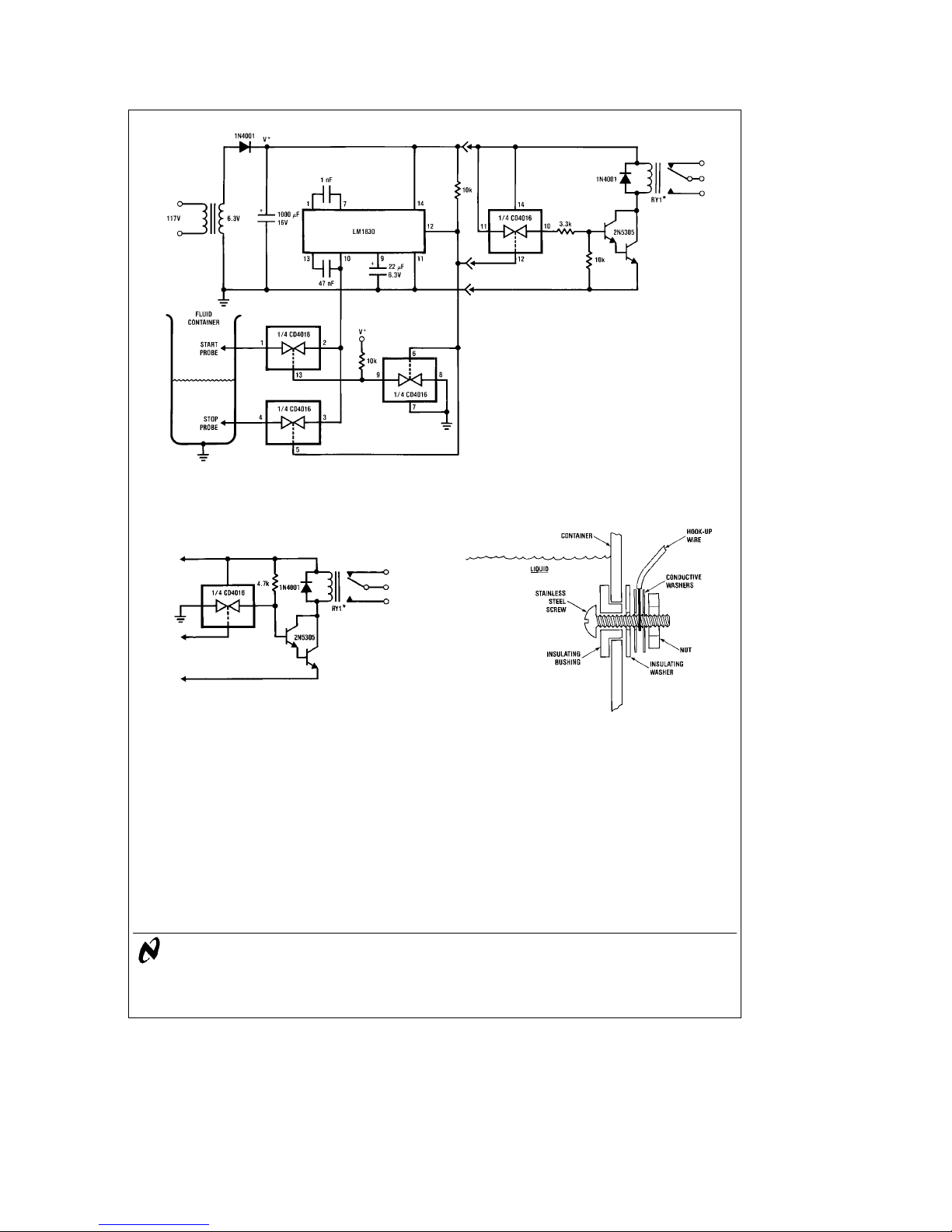
FIGURE 1(a). ‘‘Emptying’’ Processes are Controlled with this Circuit
TL/H/5071– 1
*RY1eMagnecraft PartÝW388CQX-5
FIGURE 1(b). Filling Processes are Implemented with
this Output Circuit and Relabeled Probes
LIFE SUPPORT POLICY
TL/H/5071– 2
A sealing compound applied externally protects
hook-up wire and prevents leaks.
FIGURE 2. Typical Probe Installation
NATIONAL’S PRODUCTS ARE NOT AUTHORIZED FOR USE AS CRITICAL COMPONENTS IN LIFE SUPPORT
DEVICES OR SYSTEMS WITHOUT THE EXPRESS WRITTEN APPROVAL OF THE PRESIDENT OF NATIONAL
SEMICONDUCTOR CORPORATION. As used herein:
1. Life support devices or systems are devices or 2. A critical component is any component of a life
systems which, (a) are intended for surgical implant support device or system whose failure to perform can
into the body, or (b) support or sustain life, and whose be reasonably expected to cause the failure of the life
failure to perform, when properly used in accordance support device or system, or to affect its safety or
with instructions for use provided in the labeling, can effectiveness.
be reasonably expected to result in a significant injury
to the user.
National Semiconductor National Semiconductor National Semiconductor National Semiconductor
Corporation Europe Hong Kong Ltd. Japan Ltd.
1111 West Bardin Road Fax: (
Arlington, TX 76017 Email: cnjwge@tevm2.nsc.com Ocean Centre, 5 Canton Rd. Fax: 81-043-299-2408
Tel: 1(800) 272-9959 Deutsch Tel: (
Fax: 1(800) 737-7018 English Tel: (
AB-10 Fluid Level Control Systems Utilizing the LM1830
National does not assumeany responsibility for use of any circuitry described,no circuit patent licenses are implied andNational reserves the right at any time withoutnotice to change said circuitry and specifications.
Fran3ais Tel: (
Italiano Tel: (
a
49) 0-180-530 85 86 13th Floor, Straight Block, Tel: 81-043-299-2309
a
49) 0-180-530 85 85 Tsimshatsui, Kowloon
a
49) 0-180-532 78 32 Hong Kong
a
49) 0-180-532 93 58 Tel: (852) 2737-1600
a
49) 0-180-534 16 80 Fax: (852) 2736-9960
TL/H/5071– 3
 Loading...