


 68" SR TRIPLEX – CE
OWNER'S MANUAL
Includes Operation, Maintenance and Parts Lists for SR 68" and DL 68"
NATIONAL MOWER CO. 700 Raymond Ave., P.O. Box 14299, St. Paul, Minnesota 55114-0299, U.S.A.
Phone (651) 646-4079 – Fax (651) 646-2887 www.nationalmower.com
OCTOBER – 2001

NATIONAL MOWER COMPANY
ONE YEAR
LIMITED WARRANTY
For the period of one year from the date of purchase (45 days if the product is used for rental purposes), National Mower Company will repair or replace free of charge, for the original purchaser, any part or parts found by inspection to be defective by our Factory Authorized Service Station or by the Factory at St. Paul, Minnesota to be defective in material or workmanship or both. All transportation charges on parts submitted for repair or replacement under this warranty shall be paid for by the purchaser.
This warranty does not include engines, engine parts or tires which are covered under separate warranties furnished by their manufacture or supplier.
All service under this warranty will be furnished and performed by our Factory
Authorized Service Stations.
-THERE IS NO OTHER EXPRESS WARRANTY-
IMPLIED WARRANTIES, INCLUDING THOSE OF MERCHANTABILITY AND
FITNESS FOR A PARTICULAR PURPOSE, ARE LIMITED TO ONE YEAR
FROM PURCHASE OR 45 DAYS IF THE PRODUCT IS RENTED AND TO
THE EXTENT PERMITTED BY LAW, ANY AND ALL IMPLIED WARRANTIES
ARE EXCLUDED. THE ABOVE REMEDY OF REPAIR AND REPLACEMENT
OF DEFECTIVE PARTS IS THE PURCHASER’S EXCLUSIVE REMEDY FOR
ANY DEFECT, MALFUNCTION OR BREACH OF WARRANTY. LIABILITY
FOR INCIDENTAL OR CONSEQUENTIAL DAMAGES UNDER ANY AND ALL
WARRANTIES IS EXCLUDED TO THE EXTENT PERMITTED BY LAW.
NATIONAL MOWER COMPANY
700 Raymond Avenue, St. Paul, Minnesota 55414, U.S.A.
2 |
68OMCE-10/01-350 |

NATIONAL® 68" SR & DL TRIPLEX – CE
TABLE OF CONTENTS |
|
Declaration Of Conformity............................................................................... |
4 |
Specifications |
|
Dimensions – Mower ................................................................................ |
5 |
Engine – Briggs & Straton ...................................................................... |
5 |
Disposal Numbers .................................................................................... |
5 |
Noise Emission and Vibration .................................................................. |
5 |
Safe Operating Practices ................................................................................ |
6 |
Decal (Transfer) Identification ................................................................... |
7 & 8 |
Introduction ..................................................................................................... |
9 |
Receipt Of Shipment ....................................................................................... |
9 |
Uncrating Instructions ..................................................................................... |
9 |
Assembly Instructions |
|
Rear Mower .................................................................................... |
10 & 11 |
Seat ................................................................................................ |
10 & 11 |
Wing Mowers .................................................................................. |
10 & 11 |
Engine ............................................................................................ |
10 & 11 |
Differential ...................................................................................... |
10 & 11 |
Maintenance |
|
Lubrication .............................................................................................. |
13 |
Bed Knife Replacement .......................................................................... |
14 |
Lapping and Grinding Procedures......................................................... |
15 |
Adjustments |
|
Height Of Cut .......................................................................................... |
16 |
Reel To Bed Knife Adjustment ............................................................... |
16 |
Reel End Play Adjustment ...................................................................... |
16 |
Brake Adjustment ................................................................................... |
17 |
Wing Mower Drive Belt Tension ............................................................. |
17 |
Rear Mower Drive Belt Tension ............................................................. |
17 |
Engine Drive Belt Tension ...................................................................... |
17 |
Main Drive Belt Tension ......................................................................... |
17 |
Troubleshooting ............................................................................................ |
18 |
Wiring Diagram—SR Electrical Interlock ...................................................... |
18 |
Parts List |
|
Ordering Information............................................................................... |
19 |
Frame and Running Gear ............................................................... |
20 & 21 |
Rear End ........................................................................................ |
22 & 23 |
Drive Mechanism and Wing Mower Supports ................................ |
24 & 25 |
Rear Mower .................................................................................... |
26 & 27 |
Wing Mower .................................................................................... |
28 & 29 |
Drive and Mower Skids and Shields ....................................................... |
30 |
Deluxe 68" Running Gear and Misc. Parts ............................................. |
31 |
Deluxe 68" Drive Parts ................................................................... |
32 & 33 |
Deluxe 68" Electrical Diagram ........................................................ |
34 & 35 |
3

DECLARATION OF CONFORMITY
according to Directive 89/392/EEC
We NATIONAL MOWER COMPANY
..............................................................................................................................................................
(Name of supplier)
700 Raymond Avenue, St. Paul, Minnesota 55114 U.S.A.
..............................................................................................................................................................
(Full address of the manufacturer—authorized representative in the community must also give the business name and address of the manufacturer)
declare under our sole responsibility, that the product
68" NATIONAL TRIPLEX MOWER
(Make and model)
to which this declaration relates corresponds to the relevant basic safety and health requirements of the Directive 89/392/EEC, (if applicable)
and to the requirements of other relevant Directives:
EN292-1&2--EN294--EN349
..............................................................................................................................................................
(Title and/or number and date of issue of the other Directives)
(If applicable)
For the relevant implementation of the safety and health requirements mentioned in the directives, the following standard(s) and/or technical specification(s) has (have) been respected:
ANSI B71.4
..............................................................................................................................................................
(Title and/or number and date of issue of standard(s) and/or technical specification(s))
St. Paul, MN, USA
10/15/2001
(Place and date of issue) |
(Name, function and signature of the authorized person) |
4 |
68OMCE-10/01-350 |

|
|
NATIONAL® 68" SR & DL TRIPLEX – CE |
SPECIFICATIONS |
|
|
DIMENSIONS & WEIGHT– MOWER |
|
|
Overall Length .............................................................................................. |
|
79.13" (201 cm) |
Width, Wing Mowers Folded .......................................................................... |
|
61.8" (157 cm) |
Width, Wing Mowers Down ............................................................................... |
|
76" (193 cm) |
Height ............................................................................................................ |
|
39.37"(100 cm) |
Weight (empty) ......................................................................................... |
|
639.5 lbs. (290 kg) |
ENGINE – BRIGGS & STRATTON |
|
|
Engine Type .............................. |
Forced Air Cooled, 4-cycle, Horizontal Shaft, OHV Engine |
|
Number Of Cylinders ...................................................................................................... |
|
One |
Bore and Stroke .......................................................................... |
|
2.99" x 2.17" (76 x 55 mm) |
Piston Displacement .................................................................................................... |
|
215cc |
Maximum Horsepower .................. |
7.5 hp (5.6 kW)) / 3600 rpm (Corrected per SAE J1349) |
|
Maximum Torque ............................................................ |
|
12.5 ft/lbs (16.5 N-m) at 2500 rpm |
Direction Of Rotation ............................................ |
|
Counterclockwise Facing The PTO Shaft |
Fast Idle Speed ....................................................................................................... |
|
4000 rpm |
Slow Idle Speed ...................................................................................................... |
|
1750 rpm |
Fuel ............................................................................................ |
|
Unleaded Gasoline (Petrol) |
Fuel Tank Capacity .................................................................................... |
|
4.80 US qt (4.54) |
Minimum Specific Fuel Consumption Ratio ............................... |
240 gr/hp-hr (322 gr/kW-hr) |
|
Oil ................................................................................................... |
|
Engine Oil SAE 10W-30 |
Oil Capacity .................................................................................................. |
|
1.90 US pt (.90) |
Carburetor ............................................................................. |
|
Float Type with Fixed Main Jet |
Balancing ......................................................................................... |
|
Reciprocating Balancer |
Ignition .......................................................................... |
|
Flywheel Magneto, Transistor Type |
Spark Plug ...................................................................................................... |
|
Resistor Type |
Starter ................................................. |
Recoil Starter with Automatic Compression Release |
|
Governor ............................................................................................................. |
|
Mechanical |
Lubrication Type .......................................................... |
|
Splash with Low Oil Shut-off System |
Air Cleaner ....................................................................................................... |
|
Dual Element |
Muffler ........................................................................................................... |
|
Low Tone Type |
Lighting Coil ......................................................................................................... |
|
12 V–25 W |
Charging Coil ................................................................................................................. |
|
10 A |
Net Weight (Engine) .................................................................................. |
|
59.1 lbs (26.8 kg) |
Dimensions (L x W x H) ........................... |
13.5" x 15.6" x 17.0" (344.5 x 395.5 x 432.5 mm) |
|
DISPOSAL NUMBERS |
|
|
Gasoline (Petrol), Lead Free ....................................................................................... |
|
54104 |
Engine Oil .................................................................................................................... |
|
54112 |
Fiberglass Parts ........................................................................................................... |
|
57103 |
Tires ............................................................................................................................. |
|
57502 |
Gear Oil ........................................................................................................................ |
|
54112 |
Grease ......................................................................................................................... |
|
54202 |
Plastic Tanks ................................................................................................................ |
|
57127 |
NOISE EMISSION AND VIBRATION |
|
|
Sound*: Operator Position ...................................................................................... |
|
86 dBA |
Sound Power Level (LwA) ........................................................................ |
99 dBA |
|
Vibration*: Maximum Vibration 16.1 m/s2 RMS |
|
|
Location ................................................................................................ |
|
Left Hand |
*Operating Condition: Engine rpm–3400, Unit Stationary |
||
5

IMPORTANT
National Mower Safe Operation Practices
For Riding Mowers
1.Know control functions and how to stop quickly. READ THE OWNER’S MANUAL.
2.Wear approved safety glasses or goggles when operating the mower.
3. Do not allow children to operate mower. Do not allow adults to operate mower without proper instruction.
4.Do not carry passengers. Keep children and pets at a safe distance from an operating mower.
5.Clear the work place of objects which might be picked up by the blades and thrown.
6.Disengage all reel clutches and shift into neutral before attempting to start the engine (motor). Disengage main clutch before shifting reel clutches.
7.Disengage power to the reels and stop the engine (motor) before leaving the operator’s position.
8.Disengage power to the reels and stop the engine (motor) before making any repairs or adjustments.
9.Disengage power to the reels when transporting or not in use.
10.Take all possible precautions when leaving the mower unattended, such as, shifting into neutral, setting the parking brake, stopping the engine and removing the ignition key.
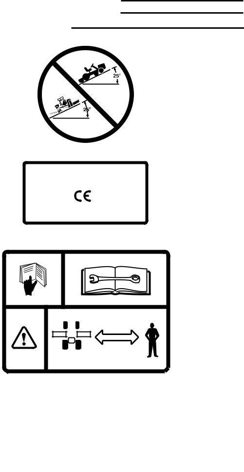
11.Do not stop or start suddenly when going uphill or downhill. Mow up and down the face of steep slopes – never across steep slopes. Do not exceed a slope of 25o in any direction.
12.Reduce travel speed on slopes and in sharp turns to prevent tipping or loss of control. Use extreme caution when changing direction on slopes.
13.Watch for holes in the terrain and other hidden hazards.
14.Watch for dangerous traffic when crossing or near roadways.
15.Never direct the discharge of material from operating reels toward bystanders nor allow anyone near the mower.
16.Handle gasoline (petro)l with CAUTION - it is highly flammable.
a.Use an approved gasoline (petrol) container.
b.Never remove the fuel tank cap or add gasoline (petrol) to a running or hot engine. Never fill the fuel tank indoors. Wipe spilled gasoline (petrol) immediately.
c.Open garage doors to allow ventilation if engine is run inside – exhaust fumes are dangerous. Do not run engine in any enclosed area.
17.Keep the mower in good operating condition. Make sure that all safety switches are operating properly and all safety guards are in place at all times, except during servicing.
18.Keep all nuts, bolts, and screws tight to be sure that the mower is in a safe working condition.
19.Never store the mower, with gasoline (petrol) in the tank, inside a building where fumes could reach an open flame or spark. Allow the engine to cool before storing in any enclosure.
20.Keep the engine free of grass, leaves or excessive grease to reduce a fire hazard.
21.The mower and reels should be stopped and inspected for damage after striking a foreign object. The damage should be repaired before restarting and operating the mower.
22.Do not change the engine governor settings or overspeed the engine.
23.Proceed as follows when mowing:
a.Mow only in the daylight or in good artificial light.
b.Never make a cutting height adjustment while the engine (motor) is running.
c.Shut the engine (motor) off when removing grass or unclogging reels.
24.This machine is to be used only as a grass cutter or lawn mower.
WARNING– California, USA residents are required by law (CA PRC 4442 & CA H & SC 13005) to equip their engines with spark arresters when operating in flammable vegitation. Arresters must be obtained from your engine dealer and are not available from National Mower Company.
6 |
68OMCE-10/01-350 |
NATIONAL® 68" SR & DL TRIPLEX – CE
TRANSFER IDENTIFICATION
1
|
|
|
|
2 |
NATIONAL MOWER CO. |
||
700 RAYMOND AVE. |
|||
ST. PAUL, MINNESOTA 55114 USA |
|||
|
651-646-4079 |
FAX 651-646-2887 |
|
YEAR OF MANUFACTURE: 2000
POWER RATING: 7.5 (5.6 kW) at 3600 RPM
WEIGHT: 639.5 lbs (290 kg)
3
4 |
|
|
|
|
|
|
|
|
|
|
|
|
|
|
|
|
|
|
|
|
|
|
|
5 |
|||||||
7

6
9
NO. |
PART NO. |
TRANSFER DESCRIPTION |
|
|
|
1 |
07358 |
Do not exceed 25o slope. Located on main belt shield. |
2 |
07358 |
Manufacturer's identification and specifications. Located |
|
|
on the main belt shield. |
3 |
07358 |
Read Operator's Manual. Refer to manual for adjustments. |
|
|
Caution: Machine is used only as a lawn mower. Keep |
away |
|
bystanders. Located on main belt shield. |
4 |
07363 |
Sound power level. Located on main belt shield. |
5 |
07363 |
Sound Level, operator's position. Located on main belt |
|
|
shield. |
6 |
07359 |
Forward, Neutral and Reverse positions. Located on main |
|
|
belt shield. |
7 |
07359 |
Rear mower clutch engagement. Located on the rear |
|
|
mower shield. |
8 |
07359 |
Wing mower clutch engagement. Located on main belt |
|
|
shield. |
9 |
07359 |
Engine clutch lever: Back, Neutral & Forward. Located on |
|
|
main belt shield. |
|
|
|
8 |
68OMCE-10/01-350 |

NATIONAL® 68" SR & DL TRIPLEX – CE
INTRODUCTION
This machine has been designed to meet European CE Safety Standards. Metric eqivalents are provided wherever possible for users outside the United States.
This manual has been prepared by National Mower Company as an aid to users for assembly, maintenance, adjustment and ordering replacement parts. Additional
information will gladly be furnished by calling or writing the manufacturer or his authorized agent.
Please furnish us with the Model Number, Serial Number and Date of Purchase when contacting us about your machine. Designations of right, left, front and rear are used as if the operator was sitting in the mower seat.
RECEIPT OF SHIPMENT
Carefully inspect your machine and crate for damage that could have occured during shipment. If damages or shortages are noted, have the transportation company’s representative note this on the bill of lading.
NOTE
Claims for shipping damages must be noted by the consignee at the point of destination and filed with the transportation company that delivers the shipment.
UNCRATING INSTRUCTIONS
In order to prevent possible damage to the machine or personal injury, the following uncrating procedure must be followed:
1.Position Crate 1 as shown in Figure A, on a hard, level surface.
2 Cut and remove all Steel Banding (2, Fig. A).
3.Remove the entire top of the crate. Unbolt Seat (3, Fig. A) from crate bracing and lay seat aside for installation later. Save the bolt and washer to use for mounting the seat mounting member.
4.Lift Rear Mower (4, Fig. A) off the crate supporting members and set aside for later attachment.
CAUTION
Handle mowers carefully with protective gloves. Reels rotate freely and are very sharp.
5.Make sure Wing Mowers (5, Fig. A) are secure to the mower frame with Wing Mower Hooks (15, Fig. B).
6.Knock down all sides of crate and remove. Roll mower
FIGURE
9
FIGURE B
10 |
68OMCE-10/01-350 |
NATIONAL® 68" SR & DL TRIPLEX – CE
ASSEMBLY INSTRUCTIONS
REAR MOWER
1.Remove two 1/2" x 1-1/2" Hex Head Bolts (1, Fig. B) and nuts from the shipping position in the Seat Hinge assembly (2, Fig. B). Position Seat Hinge Assembly with pivot facing rearward, over the seat mount of the mower frame and fasten with Bolts (1, Fig. B) and lock nuts.
2.Pivot Seat Brace (3, Fig. B) from the axle so that the top end aligns with the tab at the back of the seat hinge assembly. Fasten with a 5/16" x 1" Hex Head Bolt, Lock Washer and Hex Nut.
3.Remove the Lifter Tee (4, Fig. B) from the shipping position in the Pivot Tube (5, Fig. B) and set aside cotter pin and washer for later use. Insert the rod end of lifter tee through the slotted hole in the pad on the rear mower frame and secure with the cotter pin and washer as shown.
4.Fasten Rear Mower Pull Rod (6, Fig. B) inner leg by removing Bolts (7, Fig. B) and reinserting it through pull rod and attaching flanges on tractor axle. Note that Spacers (8, Fig. B) must be in each pivot point to allow free movement of the pull rod.
5.Attach Pull Rod (6, Fig. B) to Pivot Tube (9, Fig. B) with Pin (3, Fig. K on page 17) and Spacers (1, Fig. K). NOTE: Before completing assembly, it will be necessary to refer to the rear Mower Drive Belt Tension section and Figure K, page 17 for adjusting belt tension.
6.Install Rear Mower Belt (10, Fig. B) from Countershaft Pulley (11, Fig. B) to outer Drive Pulley (12, Fig. B). Idler Pulley (13, Fig. B) must ride on top of lower belt to provide proper tension. NOTE: It will be necessary to raise rear mower to allow enough slack to get belt over pulleys.
SEAT
1.Fasten Seat (15, Fig. B) to seat mounts by threading four 5/16" x 1" Hex Bolts (16, Fig. B), through 5/16" lockwashers, through holes in seat mounts and into the threaded holes in the bottom of the seat.
WING MOWERS
1.Remove Wing Mower Belts (17, Fig. B) from the steering column.
2.Unlock Hooks (18, Fig. B) from Wing Mower Assemblies (19, Fig. B), lower them carefully to the ground. Slip wing mower belts over Countershaft Pulleys (20, Fig. B).
3.Block mower wheels to prevent mower from moving forward. Pull Wing Mower Assemblies (19, Fig. B) forward so that they slide on Pull Rods (21, Fig. B) and compress springs. This will allow enough slack to enable belts to be installed over Reel Pulleys (22, Fig. B).
ENGINE
MOWER IS SHIPPED WITH DRY ENGINE. DO NOT START ENGINE UNTIL OIL IS ADDED TO CRANKCASE. See Engine Manual for additional information.
DIFFERENTIAL
Grease has been installed in the differential at the factory. Refer to the Maintenance Section, page 7, for additional information.
11
 Loading...