


 84" TRIPLEX – CE
OWNER'S MANUAL
INCLUDESOPERATION&MAINTENANCE
NATIONAL MOWER CO. 700RaymondAve., P.O. Box14299, St.Paul, Minnesota 55114-0299 USA
Phone (651) 646-4079 – Fax (651) 646-2887
JANUARY – 1999

NATIONAL® 84" TRIPLEX—CE
NATIONAL MOWER COMPANY
ONE YEAR
LIMITED WARRANTY
For the period of one year from the date of purchase (45 days if the product is used for rental purposes), National Mower Company will repair or replace free of charge, for the original purchaser, any part or parts found by inspection to be defective by our Factory Authorized Service Station or by the Factory at St. Paul,
Minnesota, USA to be defective in material or workmanship or both. All transportation charges on parts submitted for repair or replacement under this warranty shall be paid for by the purchaser.
This warranty does not include engines, engine parts or tires which are covered under separate warranties furnished by their manufacture or supplier.
All service under this warranty will be furnished and performed by our Factory Authorized Service Stations.
-THERE IS NO OTHER EXPRESS WARRANTY-
IMPLIED WARRANTIES, INCLUDING THOSE OF MERCHANTABILITY AND
FITNESS FOR A PARTICULAR PURPOSE, ARE LIMITED TO ONE YEAR FROM PURCHASE OR 45 DAYS IF THE PRODUCT IS RENTED AND TO THE
EXTENT PERMITTED BY LAW, ANY AND ALL IMPLIED WARRANTIES ARE
EXCLUDED. THE ABOVE REMEDY OF REPAIR AND REPLACEMENT OF
DEFECTIVE PARTS IS THE PURCHASER’S EXCLUSIVE REMEDY FOR ANY
DEFECT, MALFUNCTION OR BREACH OF WARRANTY. LIABILITY FOR INCIDENTAL OR CONSEQUENTIAL DAMAGES UNDER ANY AND ALL WAR-
RANTIES IS EXCLUDED TO THE EXTENT PERMITTED BY LAW.
NATIONAL MOWER COMPANY
700 Raymond Avenue, St. Paul, Minnesota 55414, U.S.A.
Page 3

DECLARATION OF CONFORMITY
According to Directive 89/392/EEC
We NATIONAL MOWER COMPANY
..............................................................................................................................................................
(Name of supplier)
700 Raymond Avenue, St. Paul, Minnesota 55114 U.S.A.
..............................................................................................................................................................
(Full address of the manufacturer—authorized representative in the community must also give the business name and address of the manufacturer)
declare under our sole responsibility, that the product
84" NATIONAL TRIPLEX MOWER
..............................................................................................................................................................
(Make and model)
to which this declaration relates corresponds to the relevant basic safety and health requirements of the Directive 89/392/EEC, (if applicable) and to the requirements of other relevant Directives:
EN292-1&2--EN294--EN349
..............................................................................................................................................................
(Title and/or number and date of issue of the other Directives)
(If applicable)
For the relevant implementation of the safety and health requirements mentioned in the directives, the following standard(s) and/or technical specification(s) has (have) been respected:
ANSI B71.4
..............................................................................................................................................................
(Title and/or number and date of issue of standard(s) and/or technical specification(s))
1/2/99
..............................................................................................................................................................
(Place and date of issue) (Name, function and signature of the authorized person)
Page 4 |
NL84OMCE-1/99-6C |

NATIONAL® 84" TRIPLEX—CE
TABLE OF CONTENTS
Warranty ................................................................................................................................. |
3 |
Letter Of Conformity ............................................................................................................... |
4 |
Table Of Contents .................................................................................................................. |
5 |
Specifications |
|
Dimensions – Mower ....................................................................................................... |
6 |
Engine – Briggs & Stratton 303447 ............................................................................... |
6 |
Disposal Numbers ........................................................................................................... |
6 |
Noise Emission and Vibration ......................................................................................... |
6 |
Decal (Transfer) Identification .......................................................................................... |
7—9 |
Safe Operating Practices ..................................................................................................... |
10 |
Introduction ........................................................................................................................... |
11 |
Receipt Of Shipment ............................................................................................................ |
11 |
Assembly Instructions |
|
Rear Mower ................................................................................................................... |
13 |
Wing Mower .................................................................................................................. |
13 |
Seat ............................................................................................................................... |
13 |
Wing Mower Lift ............................................................................................................ |
13 |
Tires .............................................................................................................................. |
13 |
Engine Crankcase ........................................................................................................ |
13 |
Fuel Tank ...................................................................................................................... |
13 |
Differential ..................................................................................................................... |
13 |
Operation ...................................................................................................................... |
14—15 |
Maintenance |
|
Lubrication ............................................................................................................ |
16—17 |
Adjustments |
|
Foot Brake .................................................................................................................... |
17 |
Parking Brake ............................................................................................................... |
17 |
Steering Gear ............................................................................................................... |
17 |
Wing Mower Belt Tension ............................................................................................. |
17 |
Wing Mower Pivot Operation ........................................................................................ |
18 |
Rear Axle Radius Rods ................................................................................................ |
18 |
Rear Mower Drive Belt Tension ................................................................................... |
18 |
Main Drive Belt Tension ............................................................................................... |
19 |
Chain and Clutch Adjustments ..................................................................................... |
19 |
Height Of Cut ................................................................................................................ |
19 |
Reel To Bed Knife Adjustment ..................................................................................... |
19 |
Reel End Play Adjustment ............................................................................................ |
20 |
Tires and Wheels .......................................................................................................... |
20 |
Wing Mower Lift Adjustment ......................................................................................... |
20 |
Grinding ........................................................................................................................ |
20 |
Bed Knife Replacement ................................................................................................ |
21 |
Lapping Procedure ....................................................................................................... |
21 |
Optional Equipment |
|
Roller Scraper Kit & Anti-scalp Roller Kit ............................................................. |
22—23 |
Electrical System .......................................................................................................... |
24—25 |
Troubleshooting ................................................................................................................... |
26 |
Parts List |
|
Ordering Information ..................................................................................................... |
27 |
Frame, Steering and Running Gear ............................................................................ |
29 |
Clutch Drive .................................................................................................................. |
31 |
Gear Shift and Brake .................................................................................................... |
33 |
Lower Countershaft Assembly ...................................................................................... |
34 |
Steering Gear Assembly ............................................................................................... |
35 |
Differential and Rear Axle ............................................................................................. |
37 |
Rear and Wing Mowers ................................................................................................ |
39 |
Rear Mower Lift and Drive Parts .................................................................................. |
41 |
Battery and Electrical Parts .......................................................................................... |
42 |
Manual Wing Mower Lift ............................................................................................... |
43 |
Optional Roller Scraper Kit, and Optional Anti-Scalp Kit ............................................. |
44 |
Skids, Reel End Shields and Guards ........................................................................... |
45 |
Notes ............................................................................................................................. |
46 |
Page 5

SPECIFICATIONS |
|
|
DIMENSIONS & WEIGHT—Mower |
|
|
Overall Length ............................................................................................ |
|
92-1/8” (234 cm) |
Width, Wing Mowers Folded ............................................................................ |
|
70” (178 cm) |
Width, Wing Mowers Down .............................................................................. |
|
93” (236 cm) |
Height ................................................................................................................ |
|
44” (112 cm) |
Weight (Empty) ........................................................................................... |
|
240 lbs. (528 kg) |
ENGINE—Briggs & Stratton Vanguard 303447 |
|
|
Engine Type .............................. |
Forced Air Cooled, 4-cycle, Horizontal Shaft, OHV Engine |
|
Number Of Cylinders ...................................................................................................... |
|
Two |
Bore and Stroke .......................................................................... |
|
2.68” x 2.60” (68 x 66 mm) |
Piston Displacement .............................................................................. |
|
29.3 cu. in. (480 cc) |
Maximum Horsepower ............................................................................... |
|
16 hp (11.93 kW) |
Fuel ............................................................................................ |
|
Unleaded Gasoline (Petrol) |
Fuel Tank Capacity ................................................................................. |
|
4 U.S.Gal.(15.14 l) |
Oil.................................................................................................... |
|
Engine Oil SAE 10W-30 |
Oil Capacity ............................................................................................... |
|
56 U.S. oz.(1.7 l) |
Carburetor ............................................................................................................ |
|
Float Feed |
Ignition .............................................................................................. |
|
Magnetron® Electronic |
Spark Plug ............................................................................................................... |
|
RC14YC |
Starter ........................................................................................................................ |
|
Electric |
Governor ............................................................................................................. |
|
Mechanical |
Air Cleaner ....................................................................................................... |
|
Dual Element |
Muffler ...................................................................................... |
|
Super Lo-ToneTM with Guard |
Net Weight .................................................................................................. |
|
72 lbs. (32.4 kg) |
Dimensions (Length x Width x Height) ....... |
12.75” x 15.98” x 17.28” (324 x 406 x 439 mm) |
|
DISPOSAL NUMBERS |
|
|
Gasoline (Petrol), Lead Free ....................................................................................... |
|
54104 |
Engine Oil .................................................................................................................... |
|
54112 |
Fiberglass Parts ........................................................................................................... |
|
57103 |
Tires ............................................................................................................................. |
|
57502 |
Gear Oil ....................................................................................................................... |
|
54112 |
Grease ......................................................................................................................... |
|
54202 |
Plastic Tanks ................................................................................................................ |
|
57127 |
NOISE EMISSION AND VIBRATION |
|
|
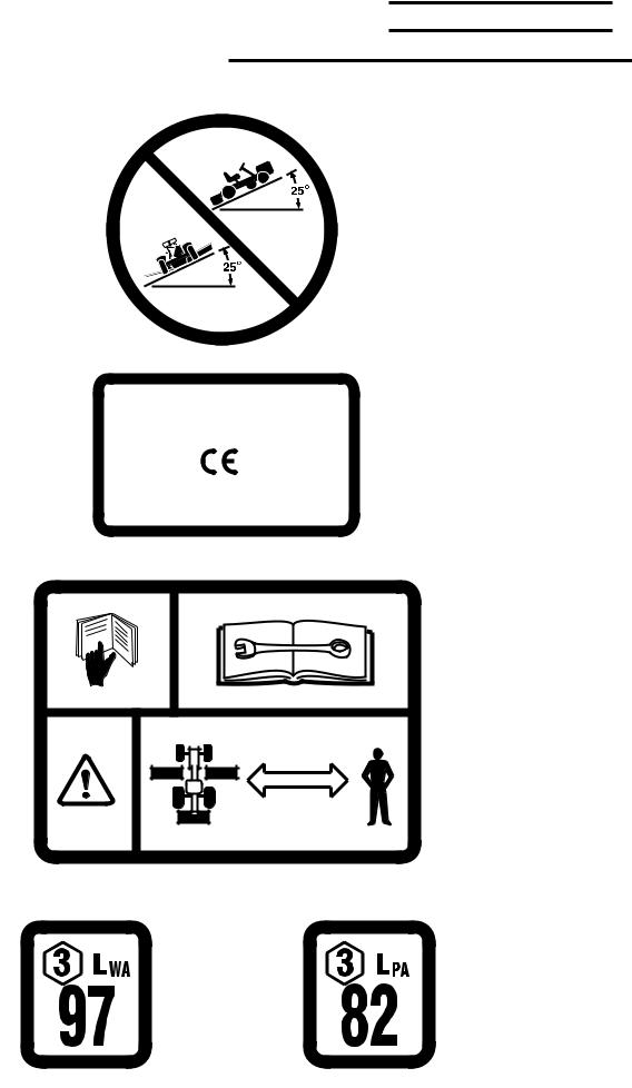
Sound*: Operator Position (LPA) ................................................................................................. |
82 dBA |
|
Sound Power Level (LWA) ........................................................................ |
97 dBA |
|
Vibration*: Maximum Vibration....................................................................... |
|
16.1 m/s2 RMS |
Location ................................................................................................ |
|
Left Hand |
*Operating Condition: Engine rpm—3100, Unit Stationary |
||
Page 6 |
NL84OMCE-1/99-6C |
NATIONAL® 84" TRIPLEX—CE
TRANSFER IDENTIFICATION
1
2
NATIONAL MOWER CO.
700 Raymond Ave.
 St. Paul, Minnesota 55114 USA
(651) 646-4079 FAX: (651) 646-2887
 YEAROFMANUFACTURE:1999
 POWER RATING: 16 HP @ 3200 RPM (11.93 KW) WEIGHT: 240 LBS. (528 kg)
3
4 |
5 |
Page 7
6
9
7
|
|
|
8 |
|
|
|
|
|
|
|
NO. |
PART NO. |
TRANSFER DESCRIPTION |
|
|
|
|
|
|
|
1 |
07358 |
Do not exceed 25o slope. Located on main belt shield. |
|
|
2 |
07372 |
Manufacturer's identification and specifications. Located |
|
|
|
|
on the main belt shield. |
|
|
3 |
07358 |
Read Operator's Manual. Refer to manual for adjustments. |
|
|
|
|
Caution: Machine is used only as a lawn mower. Keep away |
|
|
|
|
bystanders. Located on main belt shield. |
|
|
4 |
07371 |
Sound power level. Located on main belt shield. |
|
|
5 |
07371 |
Sound Level, operator's position. Located on main belt |
|
|
|
|
shield. |
|
|
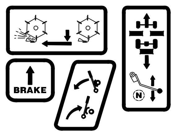
6 |
07373 |
Rear mower clutch engagement. Located on the rear |
|
|
|
|
mower belt shield. |
|
|
7 |
07373 |
Foot brake engagement. Located on main belt shield. |
|
|
8 |
07373 |
Parking brake engagement. Located on the left side of the |
|
|
|
|
seat support. |
|
|
9 |
07373 |
Main clutch lever. Located on the main belt shield. |
|
|
|
|
|
|
Page 8 |
|
|
NL84OMCE-1/99-6C |
|
NATIONAL® 84" TRIPLEX—CE
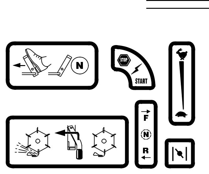
Transfer Identification Continued
12
11
10
|
|
13 |
14 |
15 |
||
|
|
|
|
|
|
|
NO. |
PART NO. |
TRANSFER DESCRIPTION |
|
|
|
|
|
|
|
|
|
|
|
10 |
07373 |
Transport clutch pedal. located on engine pulley shield. |
|
|
|
|
11 |
07373 |
Ignition on, start and stop. Located on dashboard. |
|
|
|
|
12 |
07373 |
Throttle control, fast to slow. Located on dashboard. |
|
|
|
|
13 |
07373 |
Wing mower clutch engagement. Located on left foot rest. |
|
|
|
|
14 |
07373 |
Differential shift. Located on shift lever. |
|
|
|
|
15 |
07373 |
Engine choke. Located on dashboard. |
|
|
|
|
|
|
|
|
|
|
|
Page 9

IMPORTANT
National Mower Safe Operation Practices
For Riding Mowers
1.Know control functions and how to stop quickly. READ THE OWNER’S MANUAL.
2.Wear approved safety glasses or goggles when operating the mower.
3.Do not allow children to operate mower. Do not allow adults to operate mower without proper instruction.
4.Do not carry passengers. Keep children and pets at a safe distance from an operating mower.
5.Clear the work place of objects which might be picked up by the blades and thrown.
6.Disengage all reel clutches and shift into neutral before attempting to start the engine (motor). Disengage main clutch before shifting reel clutches.
7.Disengage power to the reels and stop the engine (motor) before leaving the operator’s position.
8.Disengage power to the reels and stop the engine (motor) before making any repairs or adjustments.
9.Disengage power to the reels when transporting or not in use.
10.Take all possible precautions when leaving the mower unattended, such as, shifting into neutral, setting the parking brake, stopping the engine and removing the ignition key.
11.Do not stop or start suddenly when going uphill or downhill. Mow up and down the face of steep slopes – never across steep slopes. Do not exceed a slope of 25o in any direction.
12.Reduce travel speed on slopes and in sharp turns to prevent tipping or loss of control. Use extreme caution when changing direction on slopes.
13.Watch for holes in the terrain and other hidden hazards.
14.Watch for dangerous traffic when crossing or near roadways.
15.Never direct the discharge of material from operating reels toward bystanders nor allow anyone near the mower.
16.Handle gasoline (petro)l with CAUTION - it is highly flammable.
a.Use an approved gasoline (petrol) container.
b.Never remove the fuel tank cap or add gasoline (petrol) to a running or hot engine. Never fill the fuel tank indoors. Wipe spilled gasoline (petrol) immediately.
c.Open garage doors to allow ventilation if engine is run inside – exhaust fumes are dangerous. Do not run engine in any enclosed area.
17.Keep the mower in good operating condition. Make sure that all safety switches are operating properly and all safety guards are in place at all times, except during servicing.
18.Keep all nuts, bolts, and screws tight to be sure that the mower is in a safe working condition.
19.Never store the mower, with gasoline (petrol) in the tank, inside a building where fumes could reach an open flame or spark. Allow the engine to cool before storing in any enclosure.
20.Keep the engine free of grass, leaves or excessive grease to reduce a fire hazard.
21.The mower and reels should be stopped and inspected for damage after striking a foreign object. The damage should be repaired before restarting and operating the mower.
22.Do not change the engine governor settings or overspeed the engine.
23.Proceed as follows when mowing:
a.Mow only in the daylight or in good artificial light.
b.Never make a cutting height adjustment while the engine (motor) is running.
c.Shut the engine (motor) off when removing grass or unclogging reels.
24.This machine is to be used only as a grass cutter or lawn mower.
WARNING– California, USA residents are required by law (CA PRC 4442 & CA H & SC 13005) to equip their engines with spark arresters when operating in flammable vegitation. Arresters must be obtained from your engine dealer and are not available from National Mower Company.
Page 10 |
NL84OMCE-1/99-6C |

NATIONAL® 84" TRIPLEX—CE
INTRODUCTION
This machine has been designed to meet European CE
Safety standards. Metric equivalents are provided wherever possible for users outside the United States.
The manual has been prepared by National Mower Company as an aid to users for set-up, operating, servicing and ordering replacement parts. Additional information
will gladly be furnished by calling or writing the company.
Please furnish us with the Model Number, Serial Number and Date of Purchase when contacting us about your machine. Designations of right, left, front and rear are used in the position of the operator sitting in the mower seat.
RECEIPT OF SHIPMENT
Carefully inspect your machine and crate for damage that could have occured during shipping. If damages or shortages are noted, have the transportation company’s representative note this on the bill of lading.
NOTE
Claims for shipping damages must be noted by the consigneeatthepointofdestinationandfiledwiththetransportation company.
Page 11
12 Page
NOTE—Someguards removed or cut away to show detail
6C-1/99-NL84OMCE
FIGURE A

ASSEMBLY INSTRUCTIONS
REAR MOWER
1.Remove Rear Mower (1, Fig. A) from crate and position behind tractor as shown.
2.Pivot Rear Mower Lifter Handle (2, Fig. A) up and back to lower Rear Mower Pull Plate (3, Fig. A) on the pull yoke.
Position mounting flange on the center front of rear mower frame under the pull plate and fasten securely with two fasteners already installed in pull plate.
3.Slip V-Belt (4, Fig. A) over outer portion of Step Pulley
(5, Fig. A) located on the right side of differential case. Raise Rear Mower Belt Idler (6, Fig. A) and run V-Belt under idler pulley as shown.
4.Position Rear Mower Clutch Guard (7, Fig. A) over rear mower shaft and pulley area and fasten right side to
Support (8, Fig. A) with one 1/4"–20 x 1/2" Round Head Slotted Screw (9, Fig. A). Secure rear flange of guard with two 1/4"–20 x 1/2" Bolts (10, Fig. A), lock washers and hex nuts.
WING MOWERS
1.Remove Left Hand Mower (11, Fig. A) and Right Hand Wing Mower (12, Fig. A) from crate and position on each side of tractor so that Yoke Pins (13, Fig. A) are facing the tractor.
2.Remove the two Wing Mower Belts (14, Fig. A), that are temporarily fastened to the tractor with cable ties, and install over Countershaft Pulleys (15, Fig. A) on each side of tractor. Place other end of belt loosely over end of Wing Mower Pull Yoke (16, Fig. A).
3.Slide left hand and right hand wing mower units into position so that Yoke Pins (13, Fig. A) enter pivot holes in the pull yoke.
IMPORTANT
Forward yoke pins must pass inside belt before attaching pins to pull yokes.
4.Secure Yoke Pins (13, Fig. A) in Wing Mower Pull Yoke (16, Fig. A) with 3/4" I.D. flat washers and 1/4" x 1-1/2" cotter pins. Extra washers are supplied to be used as spacers if needed to allow a snug, but free moving pivot connection. See Figure E, page 18 for more detail.
5.Block mower wheels to prevent mower from moving forward. Pull Wing Mower Assemblies (11 and 12, Fig. A) forward so that Pull Yoke (16, Fig. A) will compress springs. This will allow enough slack to install belts over
Reel Pulleys (17, Fig. A).
SEAT
Fasten Seat (18, Fig.A) to slotted holes in Hinge Mounting
(19, Fig.A) with the four stud bolts (20, Fig. A) that are installed in the slide assembly with four 5/16“ flat washers and four 5/16"–18 lock nuts.
NATIONAL® 84" TRIPLEX—CE
WING MOWER LIFT
Stretch out Lift Chain Assemblies (21, Fig. A) and attach the longest ends to Attachment Tabs (22, Fig. A), located on the middle of the front edge of each wing mower, using 3/8"–24 x 1-3/4" Bolts, 3/8" Flat Washers and 3/8"–24 Hex
Nuts.FastentheshorterlengthcabletoCableBrackets(23,
Fig. A). Position fasteners through ends of chain so that nutslockontabsandcablebrackets,allowingchaintopivot freely between the flat washers as shown.
Test wing mower lift operation by pulling Lift Lever (24,
Fig. A) all the way back (toward the rear). Wing mowers should raise 2" to 3" above level ground. Adjust, if necessary by fastening through another link in the chain at the upper end of lift assembly.
TIRES
See Tire and Wheels, page 20 for proper inflation instructions.
ENGINE CRANKCASE
CRANKCASE OIL HAS BEEN INSTALLED AT THE FACTORY. HOWEVER, IT IS RECOMMENDED THAT ENGINE BE INSPECTED FOR PRESENCE OF OIL AT THE PROPER LEVEL BEFORE STARTING ENGINE.
See Engine Manual for details.
FUEL TANK
Check Engine Manual for correct filling instructions.
Gasoline (petrol) is highly combustible. Do not store or use near an open flame or devices such as a stove, furnace or water heater. Use gasoline (petrol) only in well ventilated areas or outdoors.
Wipe up any spills immediately.
DIFFERENTIAL
A gear lube (Mobilplex HD140) has been installed in the differential at the factory. See Maintenance Section, page 16, for additional information.
Page 13

DETAIL |
DETAIL |
A |
B |
REVERSE
NEUTRAL
FORWARD
LEFT
SIDE
RIGHT
SIDE
HOOK BRACKET WELD. |
DETAIL C |
||
|
|
|
B |
|
|
FIGUREB |
|
|
|
|
|
SWITCH ROD |
SLOTTED |
||
LOOPS |
HOLES |
||
OPERATION
The following is a description of the machine controls and their function. Refer to Figure B.
1.Steering Wheel
2.Throttle Control - Regulates mowing and travel speeds. Moving lever up and forward will increase speed. Moving lever down and back will reduce engine speed (for starting and idling engine). Never operate the mower at speeds faster than necessary to do a good, safe job.
3.Ignition Lock - Secures the machine electrical system when unattended. Insert and turn key clockwise to turn
ignition on, counterclockwise to off and key removal position.
IMPORTANT
Tractor will not start, even though ignition is on UNLESS:
A.Transport Clutch is disengaged
B.Mowing Clutch is disengaged
C.Operator is seated on the tractor
D.Wing Mower is disengaged
Page 14 |
NL84OMCE-1/99-6C |
4.Ampmeter—Optional
5.Hourmeter—Optional
6.Choke—Control and operation is covered in the engine manual.
Moving machinery can be dangerous if not operated properly. Follow all safe operation suggestions as as listed on Safe Operation Practices, Page 10.
7. Foot Brake —Designed to stop the mower. The pedal is depressed with foot to engage. It is necessary to slow
the tractor by lowering throttle and disengaging clutch lever before applying brake to prevent excessive wear and engine overload.
8. Main Clutch—Provides power to the cutting units and tractor drive. Engage clutch by moving lever forward, disengage by moving lever back (toward operator). Use this control during all mowing and slower transporting situations–withorwithouthavingthecuttingunitsengaged.
ENGAGE SLOWLY
IMPORTANT
Advance lever slowly before full engagement. Always disengage this drive before disengaging wing or rear mower drive or when stopping or leaving machine.
9. Wing Mower Lift—Provides a convenient means of manually lifting the wing mowers a few inches temporarily while the operator remains seated on the mower. It should not be used for trailer transport or storage.
Always disengage the wing and rear mower clutches (controls 13 and 14, Page 15) when not mowing and also to minimize reel and bed knife wear.
Hooks are provided at the end of each lifting chain for securing wing mowers when transporting or storing the mower. The recommended procedure is as follows:
1.Stop Mower completely.
2.Disengage Main Clutch Control (Control 8, Page 15).
3.Engage Brake Locking Lever (Control 11, Page 15).
4.Raise Wing Mowers by pulling Lifting Lever fully rearward.
5.Leave Seat and lift the outer end of each Wing Mower by grasping Handle provided on outer ends of mowers.
6.Insert the Lift Hook on each Lifting Chain through the slotted holes in the Hook Bracket Weldment and also through the loops of each Switch Rod.
NATIONAL® 84" TRIPLEX—CE
10. Differential Shift—Provides three gear positions:
Forward, neutral (center position) and reverse. Move lever forward and to the right (toward operator) until pin is beside metal tab to lock differential in a forward gear. Pin must be located in slot of tab for the neutral position and to the left of the tab (away from operator) for the reverse gear position.
Differential does not have synchro-meshed gears so you have to feel engagement.
Do not shift gears while unit is in motion or damage to differential could result.
11.Brake Locking Lever—Locks brakes in engaged position. Depress brake pedal fully. Brake lever will lock when lever is moved forward fully so that it travels over center. Refer to Detail A of Figure B.
12.Rear Mower Lifter Handle—Raises rear mower to the transport position. Pull handle up, forward and over center to lock in an UP position.
13.Rear Mower Clutch Shift Lever—Engages drive to rear mower. Pull lever forward and away from center of machine to disengage clutch jaw. To engage, pull lever forward and toward the center of machine to engage locking pin.
14.Wing Mower Clutch—Engages drive to wing mowers.
Raise lever and spring action will move lever out to engaged position. Disengage clutch by moving lever toward center of the machine, over stop and down to lock position.
Never engage drive unless wing mowers are in the lowered, cutting position.
15. TRANSPORT CLUTCH PEDAL
FOR TRANSPORT ONLY. Use when mowers are Up and Disengaged. DO NOT USE FOR MOWING!
Disengage Main Mowing Clutch (control 8) and shift to forward gear (control 10). Slowly move left foot forward to engage and back to disengage. Control disengages automatically when left foot is lifted.
NOTES
____________________________________________________________________________________________________________________________________________________________
____________________________________________________________________________________________________________________________________________________________
_____________________________________________________________________________________________________________________________________________________________
_____________________________________________________________________________________________________________________________________________________________
_____________________________________________________________________________________________________________________________________________________________
_____________________________________________________________________________________________________________________________________________________________________________________________________________________________
______________________________________________________________________________________________________________________________________________________________
Page 15
 Loading...