

Page 1
Napco Gemini
NAPCO
©
GEM-PHAST PAK Installation Instructions WI988A 10/99
What is the PHASTLink Interface?
The PHASTLink interface allows the Napco Gemini GEM-P9600 control panel to function as a fully integrated
device in a PHAST Landmark™ system. This level of integration allows drag-and-drop programming of device
features in Landmark Designer software, active data display on system keypads, and ease of installation and use.
PHASTLink provides a powerful and flexible way to connect devices to a control network that can span large
homes and even commercial installations. PHASTLink uses standard physical hardware found in 10Base-T
Ethernet networks, like Category 5 wire and RJ-45 connectors, and is compatible with several industry-standard
structured wiring specifications and standards.
PHASTLink also provides individual dynamic device addresses, high-speed data transmission, and extended cable
lengths using advanced hub technology. Typically up to 10 devices may be chained together in a single run of up to
1,000 feet. An unlimited number of individual appliances may be connected via multiple hubs.
At the core of PHASTLink is Echelon NeuronTM technology, providing tremendous potential for programmability,
functionality, and expandability. Echelon components are manufactured by Motorola and Toshiba, and provide
unmatched versatility and reliability to home automation when combined with PHASTLink protocols and Landmark
software tools.
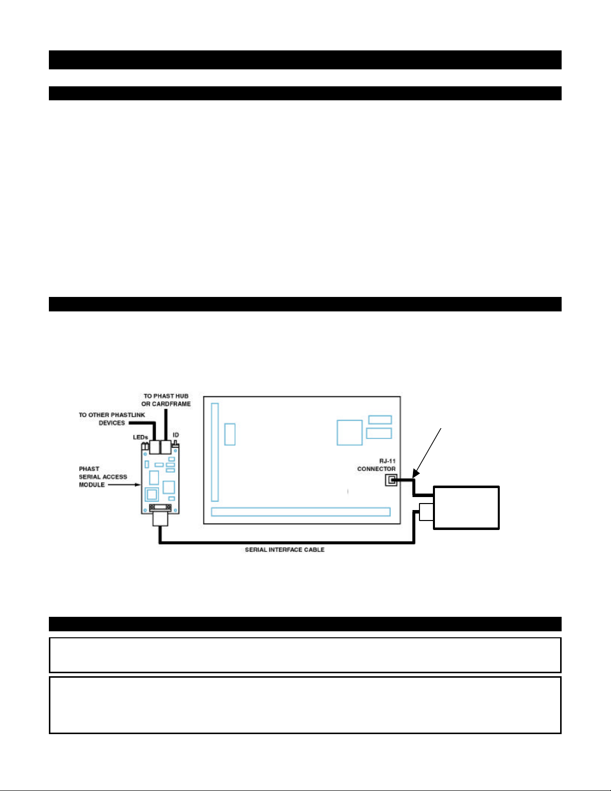
PHASTLink Interface Communications
PHASTLink communication with the Napco Gemini GEM-P9600 control panel is handled by a PHAST serial access
module (SAM), which has been configured to ensure compatibility with the Gemini panel. The SAM is connected to
the GEM-RS232 Serial Converter, which connects to the serial port of the Gemini Panel. The serial cable uses DB9 connectors at the SAM and the GEM-RS232 and an RJ-11 cable connects the RS232 to the Gemini board. The
SAM and the GEM-RS232 may be installed inside the Gemini panel cabinet.
6 CONDUCTOR RJ12
STYLE CABLE
(SUPPLIED)
NAPCO GEM-P9600
GEM-RS232
CONVERTER
The serial interface parameters are: Baud = 9600, Parity = None, Stop Bits = 1, and Data Bits = 8.
Note: The GEM-P9600 must have the EPROM included in the GEM-PHAST PAK installed in it. This special
home automation EPROM is identified by the version number followed by the letters HA. For example, V11C HA.
Hardware Installation and Configuration
WARNING! DANGEROUS VOLTAGE!
To reduce the risk of serious injury or death, turn all power off before installing this equipment.
Caution:
Many electronic components are static sensitive. If possible, install these components in a static-free work
environment. Otherwise, touch a grounded metal object to discharge any static charge before handling these
components. Do not touch any live electrical conductors.
Page 2

1. Before connecting and configuring the PHASTLink interface, you must install, program, and test the Napco
Gemini system according to the manufacturer's instructions.
2. Turn off power to the Gemini panel.
3. Connect the GEM-RS232 module to the Gemini panel with the supplied RJ-11 style modular to modular cable.
4. Connect the DB-9 connector of the serial cable to the serial connector on the GEM-RS232 module.
5. Connect the DB-9 connector on the other end of the serial cable to the serial connector on the SAM module.
6. Connect the SAM to the Landmark system with a PHASTLink cable, using either of the RJ-45 PHASTLink ports
on the SAM. As with any other PHASTLink-compatible devices, additional devices may be daisy-chained from
the SAM.
7. Turn on the power to the Gemini panel. The red LED on the SAM should illuminate. The green LED will flash
every two seconds until it establishes contact with a PHAST Master Control Unit (MCU), at which point the
greed LED will shut off. The green LED will then flash whenever data is sent and received, indicating that the
Gemini panel is communicating with the PHASTLink network.
8. Go to "Landmark Software Configuration and Programming."
Landmark Software Configuration
This is only a general outline of the steps used in Landmark Designer to configure and program the Napco Gemini
panel as a Landmark system device. Refer to the Landmark online help for more detailed instructions.
1. Start the Landmark Designer program and open the appropriate project file.
2. Look in Files > Supported Manufacturers to make sure that the NAPCO products are included in the list of
supported manufacturers. If not, check the box next to NAPCO and add it to the list.
3. Obtain a list of NAPCO sensors and other devices that have been (or will be) configured in the NAPCO panel.
4. Select the NAPCO tab in the Device toolbar and drag an icon for each of these sensors or other devices onto
the appropriate rooms in the project. Do this in the same manner as for other Landmark system devices.
5. Have Landmark Designer "Specify Hardware" for the project after adding the NAPCO sensors or devices.
6. Carry out the network assignment steps for the NAPCO alarm panel, as follows:
a. Click on the Network task button.
b. Select the Attachments tab.
c. The NAPCO panel should be listed in the Unattached Software list box and the Unattached Hardware list
box.
Note: The NAPCO alarm panel and the SAM module must be connected and powered-up for the NAPCO
panel to appear in the Unattached Hardware list box.
d. Select NAPCO Panel in the Unattached Software list box.
e. Click the Identify button (or check the Auto Attach check box). The NAPCO panel should appear in the
Attached Hardware list box.
7. Bring up the Properties window for each sensor or device that you added from the NAPCO device tab and
select the Configuration tab. Make any required configuration changes for that particular device. Configuration
options include:
• Zone Number – This represents the logical zone programmed to correspond to the physical input contact of
the NAPCO panel. These can be auto-numbered or manually entered.
• Open/Closed – This indicates whether the zone contacts are normally open or normally closed for
default/ready status.
• Master Security Code – Each NAPCO panel has a unique Master Security Code. This code must be
entered in this field to establish proper communication with the panel.
8. Test the NAPCO panel from a NAPCO device's Control tab.
Click on the Arm or Disarm buttons and make sure that the panel actually arms or disarms. This will determine
if end-to-end communication is working.
If the panel fails to arm or disarm, or if any events in the zone(s) going into the alarm panel are not working,
check the following:
• Check the network log and make sure that the Master Security Code is correct.
of 6 7/17/99 WI9882
Page 3

• Check the LED status on the SAM module. The SAM's green LED indicates that it is powered up. If this
LED is not on, check the cable connection. Also, follow the cable back to the PHASTLink hub or cardframe
and check the connection at that end.
• Make sure that the correct NAPCO chip is in installed. It must be Vxx HA. "HA" indicates that it is a home
automation chip.
• If a PHAST touchpanel displays an "Out of System" message, unplug the SAM from the network and plug it
back in. This should fix the problem in a few seconds.
9. To program the device, click the Program button. The Programming window appears. Refer to Programming
the Landmark System for general programming instructions. The following section, Programming Options, lists
the available programming features for this device.
10. Make any keypad or touchpanel menu programming changes associated with the NAPCO alarm panel in the
same manner as for other Landmark System devices.
11. After making any additional changes, test the NAPCO alarm panel again from a PHAST keypad or touchpanel
or from a NAPCO device's Control tab.
From the Control tab:
a. Make sure the this device and any associated devices have been installed, their properties configured, the
control devices specified by Landmark Designer, and that all devices have been programmed.
b. Use the controls on the Control tab sheet as if it were a remote control. Make sure the device responds
correctly to the commands. There are buttons for Arm and Disarm on the Control tab.
If you experience problems, refer to the Technical Support section.
Programming Options in the Programming Window
Events
All events for sensors are handled through the NAPCO panel, which is found in the Equipment Room. Events
correspond to zones in the security system. The Event dialog box has a drop-down list box to allow the
selection of the zone, and an option to select Protected On or Protected Off. The following events are
supported:
• Zone – This indicates the zone in which the event will take place.
• Status – This refers to whether the zone is going into alarm or becoming secure again.
• Protected – This refers to the state of the panel, which is either armed or disarmed.
Commands
Only two commands are possible:
• Arm
• Disarm
Conditionals
Conditionals are programmed on the NAPCO panel itself. Each zone can be checked to see if the status is
either:
• Secure
• In Alarm
Menus
No menu items can be auto-generated for the NAPCO panel.
Variables
No variables are supported.
of 6 7/17/99 WI9883
Page 4

PHASTLink Cable Information
RJ-45SocketRJ-45Plu
g
This section contains information that you will need to make PHASTLink cables, plus general information on
connecting PHASTLink devices.
PHASTLink cables are used to connect all PHASTLink-compatible devices, including keypads, dimmers, J-box IR
devices, amplifiers, audio switches, etc.
PHASTLink uses a standard 10Base-T connection (i.e. Category 5 wire and RJ-45 connectors). The wire should be
connected in the standard manner, as shown in the following figure. If a consistent color code is used, wiring
problems will be minimized.
Pin # Wire Color Polarity Function
1 White/Green + Transmit
2 Green – Transmit
112233445566778
8
3 White/Orange – Mic
4 Blue – Ground
5 White/Blue + 12VDC
6 Orange + Mic
7 White/Brown + Receive
8 Brown – Receive
It is important that the correct pairing is observed. Transmit, receive, and mic need to be on twisted pairs. Splitting
pairs (e.g., using a white/green wire with a blue/white wire for transmit) will result in increased crosstalk, and may
result in bus failure or noise on the intercom.
If a PLB-CF10 cardframe is used, a 15-port
hub is built into the cardframe. The maximum
length of wire per port is 1,000 feet. Each
PHASTLink device has two RJ-45 connectors
to allow multiple devices to be daisy chained
on one PHASTLink port. Refer to the PLBCF10 documentation for more detailed
connection information.
The limit for each home run is 10 PHASTLink
devices. Extra hubs can be added to provide
additional ports.
Note: Only one PHAST keypad can be used
per port, so home-run each keypad.
For optimum performance, PHAST
recommends the installation of a double 120ohm terminator in one of the RJ-45 jacks of
the last device (or the only device) in a chain
of PHASTLink devices.
To build a double 120-ohm terminator:
a. Install a 120-ohm resistor (1/4-watt or larger) between pins 1 and 2 of an RJ-45 connector.
b. Install a 120-ohm resistor (1/4-watt or larger) between pins 7 and 8 of the same RJ-45 connector.
of 6 7/17/99 WI9884
Page 5

PHAST LCD keypads must connect
directly to a PHAST Hub (or PHAST
Microphone Hub). Due to power
requirements and/or the need for a
separate microphone line for each
keypad, they cannot be daisy
chained to other LCD keypads; they
can, however be daisy chained with
other PHASTLink devices.
When connecting PHAST keypads
that will be used as intercoms, the
Microphone Hub taps off the
intercom audio signal carried on the
PHASTLink cable from that keypad.
PHASTLink devices cannot be wired in a star configuration.
Troubleshooting
The green LED on the SAM is not illuminated.
This condition indicates that the SAM is not powered up. Check the following:
• Make sure the Landmark system is running.
• Follow the PHASTLink cable back to the PHASTLink hub or cardframe, and check the RJ-45 connections, as
described in "PHASTLink Cable Information."
• Check the Network Assignments tab in the Landmark Designer software and make sure the Vantage Q System
has been properly identified and logically connected.
of 6 7/17/99 WI9885
Page 6

NAPCO SECURITY SYSTEMS, INC. (NAPCO)
warrants its products to be free from manufacturing
defects in materials and workmanship for 12 months
following the date of manufacture. NAPCO will, within
said period, at its option, repair or replace any product
failing to operate correctly without charge to the original
purchaser or user.
This warranty shall not apply to any equipment, or any
part thereof, which has been repaired by others,
improperly installed, improperly used, abused, altered,
damaged, subjected to acts of God, or on which any
serial numbers have been altered, defaced or removed.
Seller will not be responsible for any dismantling or
reinstallation charges.
expressly cancelled. NAPCO neither assumes, nor
authorizes any other person purporting to act on its
behalf to modify, to change, or to assume for it, any
other warranty or liability concerning its products.
In no event shall NAPCO be liable for an amount in
excess of NAPCO's original selling price of the product,
for any loss or damage, whether direct, indirect,
incidental, consequential, or otherwise arising out of
any failure of the product. Seller's warranty, as
hereinabove set forth, shall not be enlarged, diminished
or affected by and no obligation or liability shall arise or
grow out of Seller's rendering of technical advice or
service in connection with Buyer's order of the goods
furnished hereunder.
THERE ARE NO WARRANTIES, EXPRESS OR
IMPLIED, WHICH EXTEND BEYOND THE
DESCRIPTION ON THE FACE HEREOF. THERE IS
NO EXPRESS OR IMPLIED WARRANTY OF
MERCHANTABILITY OR A WARRANTY OF FITNESS
FOR A PARTICULAR PURPOSE. ADDITIONALLY,
THIS WARRANTY IS IN LIEU OF ALL OTHER
OBLIGATIONS OR LIABILITIES ON THE PART OF
NAPCO.
Any action for breach of warranty, including but not
limited to any implied warranty of merchantability, must
be brought within the six months following the end of
the warranty period.
IN NO CASE SHALL NAPCO BE LIABLE TO ANYONE
FOR ANY CONSEQUENTIAL OR INCIDENTAL
DAMAGES FOR BREACH OF THIS OR ANY OTHER
WARRANTY, EXPRESS OR IMPLIED, EVEN IF THE
LOSS OR DAMAGE IS CAUSED BY THE SELLER'S
OWN NEGLIGENCE OR FAULT.
In case of defect, contact the security professional who
installed and maintains your security system. In order to
exercise the warranty, the product must be returned by
the security professional, shipping costs prepaid and
insured to NAPCO. After repair or replacement, NAPCO
assumes the cost of returning products under warranty.
NAPCO shall have no obligation under this warranty, or
otherwise, if the product has been repaired by others,
improperly installed, improperly used, abused, altered,
damaged, subjected to accident, nuisance, flood, fire or
acts of God, or on which any serial numbers have been
altered, defaced or removed. NAPCO will not be
responsible for any dismantling, reassembly or
reinstallation charges.
This warranty contains the entire warranty. It is the sole
warranty and any prior agreements or representations,
whether oral or written, are either merged herein or are
NAPCO RECOMMENDS THAT THE ENTIRE SYSTEM
BE COMPLETELY TESTED WEEKLY.
Warning: Despite frequent testing, and due to, but not
limited to, any or all of the following; criminal tampering,
electrical or communications disruption, it is possible for
the system to fail to perform as expected. NAPCO does
not represent that the product/system may not be
compromised or circumvented; or that the product or
system will prevent any personal injury or property loss
by burglary, robbery, fire or otherwise; nor that the
product or system will in all cases provide adequate
warning or protection. A properly installed and
maintained alarm may only reduce risk of burglary,
robbery, fire or otherwise but it is not insurance or a
guarantee that these events will not occur.
CONSEQUENTLY, SELLER SHALL HAVE NO
LIABILITY FOR ANY PERSONAL INJURY,
PROPERTY DAMAGE, OR OTHER LOSS BASED ON
A CLAIM THE PRODUCT FAILED TO GIVE
WARNING. Therefore, the installer should in turn
advise the consumer to take any and all precautions for
his or her safety including, but not limited to, fleeing the
premises and calling police or fire department, in order
to mitigate the possibilities of harm and/or damage.
NAPCO is not an insurer of either the property or safety
of the user's family or employees, and limits its liability
for any loss or damage including incidental or
consequential damages to NAPCO's original selling
price of the product regardless of the cause of such loss
or damage.
Some states do not allow limitations on how long an
implied warranty lasts or do not allow the exclusion or
limitation of incidental or consequential damages, or
differentiate in their treatment of limitations of liability for
ordinary or gross negligence, so the above limitations or
exclusions may not apply to you. This Warranty gives
you specific legal rights and you may also have other
rights which vary from state to state.
 Loading...