

Page 1

R
333 Bayview Avenue
Amityville, New York 11701
For Sales and Repairs, (800) 645-9445
For Technical Service, (800) 645-9440
GEM-2D Second Door
Access Control Accessory
INSTALLATION INSTRUCTIONS
© Napco 2004
GENERAL DESCRIPTION
The GEM-2D is a module that connects to the GEM-
ACM1D, an accessory that adds integrated access control
to the burglary alarm functions of the GEM-X255 control
panel. The GEM-ACM1D provides controlled access to a
door by releasing a locking device (such as a magnetic lock
or electric strike) when the proper credential is presented to
the card reader. The GEM-2D allows the GEM-ACM1D to
independently control a second access relay using a separate card reader. For a full description of the GEM-ACM1D,
see WI1221.
Two readers can be used to control one door. Each reader
can be programmed to allow its own independent access
schedules to control both exit and entry permissions for a
single door.
The GEM-2D is basically identical to the GEM-ACM1D, except that the GEM-2D uses separately wired card readers,
door contacts and locking device relays that all function in
the same manner as the GEM-ACM1D.
Readers connected to the GEM-2D do not provide
Note:
Arm/Disarm capability.
Access control is integrated with the burglary functions of
the GEM-X255. It can be used to arm and disarm the system, annunciate and report alarms and troubles, and monitor the access door without the need for additional contacts.
Up to 4 GEM-ACM1D modules may be connected to a
GEM-X255 control panel via standard, unshielded station
wire. Each module is capable of controlling access through
2 doors and uses a keypad location in the system for communication. Any polling failures, AC/DC Power or Battery
Troubles associated with the ACM will be displayed as a
KEYPAD/ACM TROUBLE
Tamper will be displayed as a
other keypads. GEM-X255 panel code version 5 or higher
must be used for GEM-ACM1D module installations.
Although the GEM-ACM1D and the GEM-2D perform all
access decisions immediately without consulting the panel,
the panel limits the number of users to 195. In addition, the
Event Scheduler (requires use of PCD-Windows Quickloader download software) is used to control user access
by scheduling "User Off" and "User On" events, with the
total number of events is limited by the panel to 255. Note:
Be aware that more than one event can be assigned to
* UL installations require JP3 to be removed.
** Not Evaluated by UL.
*** Requires GEM-2D to be installed.
at the other keypads. Any ACM
KEYPAD/ACM TAMPER
at
WI1239A 6/04
each user, and the total number of events allowed is always
limited to 255 regardless of how many users are programmed.
The GEM-ACM1D requires the panel for uploading user
codes/attributes (and their associated schedules), uploading
door attributes, digital dialer reporting and all Keypad/ACM
trouble/information displays.
Each of the two model 6005B access card readers can be
programmed to function independently on different doors, or
together controlling access for both sides of one door. The
GEM-ACM1D supports a variety of card readers, including
the Polaris XYZ magnetic card reader, the ShadowProx
proximity card reader, the HID proximity readers, and the 26bit standard Wiegand card readers. The GEM-ACM1D also
supports the use of any "Request to Exit" device, including
the T-Rex exit detector.
SPECIFICATIONS
Housing Dimensions: 11"x12
xWx
D
H
GEM-X255 Current Draw
: 5mA
1
/8"x3" (28x30.8x7.6cm)
Operating Temperature: 0–49°C (32-120°F)
Input Power: 16.5VAC via CLASS 2 Plug-In 50VA Trans-
former
Door Zone Loop Voltage:
10-13VDC
Door Zone Loop Current: 2.4mA with 2.2K EOLR
Door Zone Loop Resistance: 300 ohms maximum
Combined Door Lock Power
: D1 PWR (terminals 3+ and
4-) + D2 PWR (terminals 5+ and 6-)
Voltage Rating: 12VDC
Maximum Current: 1.5A
Battery Standby Time:
1. JP3 not installed: Standby Time = 0*
2. JP3 installed: Refer to battery standby chart in
WI1221**
Reader 1 PWR:
READER 1 PWR (terminals 17+ and 18-)
Voltage Rating: 12.5VDC to 11.7VDC with JP1 set to
12V. 5V with JP1 set to 5V.
Maximum Current: 125mA
Battery Standby Time:
1. JP3 not installed and 4AH battery used = 4 Hour*
2. JP3 installed: Refer to battery standby chart in
WI1221**
Reader 2 PWR***:
READER 2 PWR (terminals 35+ and 36-)
Voltage Rating: 12.5VDC to 11.7VDC with JP4 set to
12V. 5V with JP4 set to 5V.
Maximum Current: 125mA
Battery Standby Time:
1
Page 2
1. JP3 not installed and 4AH battery used = 4 Hour*
2. JP3 installed: Refer to battery standby Chart in
WI1221**
POWER SUPPLY
The integral power supply includes two primary linear regulators. The first regulator is used to power the panel, the
card readers and to re-charge the battery. The panel and
card readers are supported with battery standby. The second regulator is used to supply up to 1.5A 12VDC for the
door locks, which provides enough current to support two
750mA magnetic locks. The Door Lock Power has an option to enable battery standby with a shunt connector
placed across jumper JP3. The battery is prevented from
damage caused during extended power failures with a battery drop out circuit that disconnects the battery when there
is no AC present and battery voltage drops to approximately 9VDC. When AC is restored, the battery is automatically re-connected and begins to recharge.
The GEM-ACM1D tests the battery under load every 4
hours and when the RESET button is pressed. The low
battery condition will only restore after it passes the active
test. The duration of this test is 15 seconds.
There are several advantages to this power supply design.
The separation of the door lock power from the rest of the
system reduces the likelihood that turning off the power to
the door lock coils will affect performance of the system.
The use of linear versus switching regulators significantly
reduces electrical noise that may hinder the sensitivity of
proximity card readers.
SYSTEM REQUIREMENTS
The following system hardware is required:
Gemini GEM-X255 Control Panel version 5 or higher.
EPROM Upgrade must be installed in control panel.
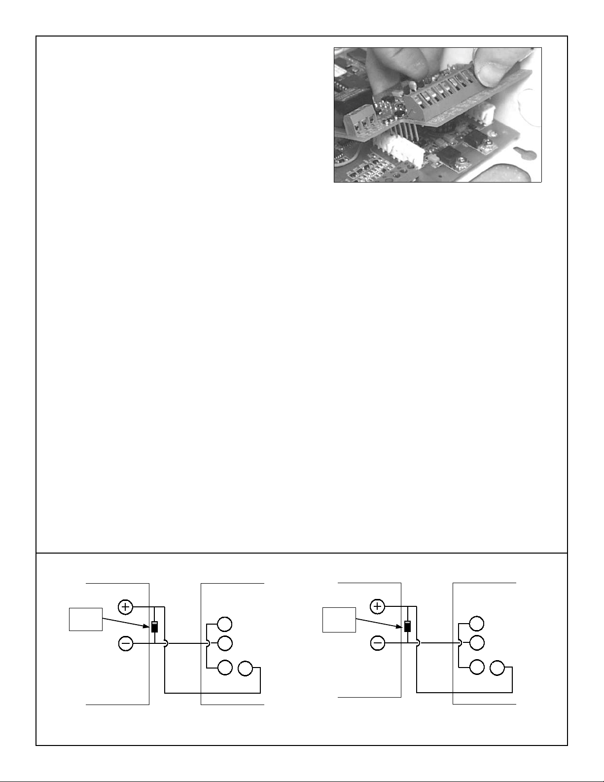
INSTALLING THE GEM-2D
When connecting the GEM-2D to the GEM-ACM1D, insert
the pins of the GEM-2D into receptacles J4F and J5F located on top of the GEM-ACM1D. Before inserting, align all
pins and receptacle sockets, then fully insert the GEM-2D
Figure 1: Installing the GEM-2D. Before inserting, align all pins and
receptacle sockets, then fully insert the GEM-2D into receptacles J4F
and J5F located on top of the GEM-ACM1D.
into the GEM-ACM1D. See Figure 1 illustrating the installation of the GEM-2D into the GEM-ACM1D.
GEM-2D WIRING/CONFIGURATION
Connect 2nd Door Strike (Mag Lock).
NOTE: Before installation, always check with local laws
having jurisdiction concerning the installation of magnetic locking devices. There may be strict limitations
with regard the installation of magnetic or similar exit
door locking devices. Local laws may require the installation of electrically separate panic hardware to ensure
the door can be opened in the event of an emergency.
Door strike outputs are controlled by schedules pro-
grammed into the panel. These door strike outputs can
operate DC-powered locking devices such as magnetic
door locks or other electromechanical locks and can be
configured to operate in "Fail Secure" (which remain
locked when power fails) or "Fail Safe" (which unlock
when power fails) configurations.
For normally closed door strikes, connect ground to ter-
minal 4, wire terminal 3 to terminal 14, then connect the
positive door strike wire to terminal 16. See Figs. 2 and
3 below. The GEM-ACM1D can supply a constant combined maximum 12V output of 1.5A for D1-PWR and
D2-PWR.
Lock Wiring for the GEM-2D
Clamping
Diode
(supplied)*
Magnetic Lock GEM-2D
Fig. 2: Normally Energized Lock Wiring ("Mag Lock")
* The diodes shown above are used to reduce the electrical noise produced when internals coils of the magnetic lock are de-energized.
2
(+) D2 PWR
5
(–) D2 PWR
6
32
34
COM N/C
Clamping
Diode
(supplied)*
Electric Strike
Fig. 3: Normally De-Energized Lock Wiring
(+) D2 PWR
5
(–) D2 PWR
6
32
33
COM N/O
GEM-2D
Page 3

3
Page 4

NAPCO LIMITED WARRANTY
NAPCO SECURITY SYSTEMS, INC. (NAPCO)
warrants its products to be free from manufacturing
defects in materials and workmanship for thirty-six
months following the date of manufacture. NAPCO will,
within said period, at its option, repair or replace any
product failing to operate correctly without charge to the
original purchaser or user.
This warranty shall not apply to any equipment, or
any part thereof, which has been repaired by others,
improperly installed, improperly used, abused, altered,
damaged, subjected to acts of God, or on which any
serial numbers have been altered, defaced or removed.
Seller will not be responsible for any dismantling or
reinstallation charges.
THERE ARE NO WARRANTIES, EXPRESS OR
IMPLIED, WHICH EXTEND BEYOND THE
DESCRIPTION ON THE FACE HEREOF. THERE IS
NO EXPRESS OR IMPLIED WARRANTY OF
MERCHANTABILITY OR A WARRANTY OF FITNESS
FOR A PARTICULAR PURPOSE. ADDITIONALLY,
THIS WARRANTY IS IN LIEU OF ALL OTHER
OBLIGATIONS OR LIABILITIES ON THE PART OF
NAPCO.
Any action for breach of warranty, including but not
limited to any implied warranty of merchantability, must
be brought within the six months following the end of the
warranty period.
IN NO CASE SHALL NAPCO BE LIABLE TO
ANYONE FOR ANY CONSEQUENTIAL OR
INCIDENTAL DAMAGES FOR BREACH OF THIS OR
ANY OTHER WARRANTY, EXPRESS OR IMPLIED,
EVEN IF THE LOSS OR DAMAGE IS CAUSED BY
THE SELLER'S OWN NEGLIGENCE OR FAULT.
In case of defect, contact the security professional
who installed and maintains your security system. In
order to exercise the warranty, the product must be
returned by the security professional, shipping costs
prepaid and insured to NAPCO. After repair or
replacement, NAPCO assumes the cost of returning
products under warranty. NAPCO shall have no
obligation under this warranty, or otherwise, if the
product has been repaired by others, improperly
installed, improperly used, abused, altered, damaged,
subjected to accident, nuisance, flood, fire or acts of
God, or on which any serial numbers have been altered,
defaced or removed. NAPCO will not be responsible for
any dismantling, reassembly or reinstallation charges.
This warranty contains the entire warranty. It is the
sole warranty and any prior agreements or
representations, whether oral or written, are either
merged herein or are expressly canceled. NAPCO
neither assumes, nor authorizes any other person
purporting to act on its behalf to modify, to change, or to
assume for it, any other warranty or liability concerning
its products.
In no event shall NAPCO be liable for an amount in
excess of NAPCO's original selling price of the product,
for any loss or damage, whether direct, indirect,
incidental, consequential, or otherwise arising out of any
failure of the product. Seller's warranty, as hereinabove
set forth, shall not be enlarged, diminished or affected by
and no obligation or liability shall arise or grow out of
Seller's rendering of technical advice or service in
connection with Buyer's order of the goods furnished
hereunder.
NAPCO RECOMMENDS THAT THE ENTIRE
SYSTEM BE COMPLETELY TESTED WEEKLY.
Warning:
not limited to, any or all of the following: criminal
tampering, electrical or communications disruption, it is
possible for the system to fail to perform as expected.
NAPCO does not represent that the product/system may
not be compromised or circumvented; or that the product
or system will prevent any personal injury or property
loss by burglary, robbery, fire or otherwise; nor that the
product or system will in all cases provide adequate
warning or protection. A properly installed and
maintained alarm may only reduce risk of burglary,
robbery, fire or otherwise but it is not insurance or a
guarantee that these events will not occur.
CONSEQUENTLY, SELLER SHALL HAVE NO
LIABILITY FOR ANY PERSONAL INJURY, PROPERTY
DAMAGE, OR OTHER LOSS BASED ON A CLAIM
THE PRODUCT FAILED TO GIVE WARNING.
Therefore, the installer should in turn advise the
consumer to take any and all precautions for his or her
safety including, but not limited to, fleeing the premises
and calling police or fire department, in order to mitigate
the possibilities of harm and/or damage.
NAPCO is not an insurer of either the property or
safety of the user's family or employees, and limits its
liability for any loss or damage including incidental or
consequential damages to NAPCO's original selling
price of the product regardless of the cause of such loss
or damage.
Some states do not allow limitations on how long an
implied warranty lasts or do not allow the exclusion or
limitation of incidental or consequential damages, or
differentiate in their treatment of limitations of liability for
ordinary or gross negligence, so the above limitations or
exclusions may not apply to you. This Warranty gives
you specific legal rights and you may also have other
rights which vary from state to state.
Despite frequent testing, and due to, but
4
 Loading...