

Page 1
FW-DACT
Digital Communicator
INSTALLATION and OPERATION MANUAL
LNOTICE
All information, documentation, and specifications contained in this manual are subject to change
without prior notice by the manufacturer.
©1999 by NAPCO Security Systems, Inc.
October 14, 1999
LT-639NAP Rev.7
Page 2

TABLE of CONTENTS
INTRODUCTION - MODELS & FEATURES ..........................................................Page 1
Notice for all FW-DACT, Sold in Canada ........................................................Page 2
Notice for all FW-DACT, Sold in the U.S.A. ...................................................... Page 2
CONNECTIONS AND SETTINGS ................................................................. Page 3
FIELD WIRING ...............................................................................Page 4
SYSTEM CONFIGURATION & OPERATION ........................................................Page 5
REPORTING FORMATS ........................................................................ Page 7
COMPATIBLE FIRE ALARM CONTROL PANELS .....................................................Page 8
COMPATIBLE RECEIVERS ......................................................................Page 8
SPECIFICATIONS .............................................................................Page 9
BATTERY CALCULATIONS ...................................................................... Page 9
WARRANTY ..................................................................................Page 10
Page 3

INTRODUCTION - MODELS & FEATURES
FW-DACT: A single board Digital Communicator that can connect via Contact Closure Inputs on a single ribbon cable
to a NAPCO Fire Alarm Control Panel (FACP) such as the FW-C2Z, FW-C4Z or FW-C4EZ. It can transmit
Common Alarm, Common Supervisory, and Common Trouble information on two telephone lines.
T Communicates to a FACP via Contact Closure Inputs (FW-DACT).
T User Configurable with FW-PCTOOL Configuration Tool. This includes a 4-Line LCD Display and Keypad in a rugged
metal enclosure, with a ribbon cable to connect to the Communicator.
T Communicates to a Central Monitoring Station using Ademco Contact ID or SIA DCS Protocols.
T The FW-DACT can transmit Common Alarm, Common Supervisory and Common Trouble information on two
telephone lines.
The DACT continuously supervises the state of each of two connected Telco Lines (at approximately 1 minute intervals)
by both a Line-DC level measurement, and by checking for a Dial-Tone. If either fails, a Line #1 or Line #2 Trouble event
will be reported. Once a Line has been restored, a Line Trouble Restored event will be reported. The product will always
report events sorted in the order in which they are received / recognized. The products are capable of reporting multiple
events to a single Account number, within a single call session. Up to 4 retries, for a single message not yet reported,
will be made within a single call-attempt. A failure to communicate to either or both Accounts will generate a
corresponding event which will be queued for reporting.
Page 1
Page 4

Notice for all FW-DACT Sold in Canada:
NAPCO’s FW-DACT Digital Communicator described in this manual are listed by Underwriters Laboratories Canada (ULC)
for use in slave application in conjunction with a Listed Fire Alarm Control Panel under Standard ULC-S527 (Standard for
Control Units for Fire Alarm Systems) and ULC/ORD-C693-1994 (Central Station Fire Protective Signalling Systems and
Services). These Communicators should be installed in accordance with this manual; the Canadian / Provincial / Local
Electrical Code; and/or the local Authority Having Jurisdiction (AHJ).
Industry Canada Notice:
The Industry Canada label identifies certified equipment. This certification means that the equipment meets certain
telecommunications network protective, operational and safety requirements. Industry Canada does not guarantee the
equipment will operate to the user's satisfaction. Before installing this equipment, users should ensure that it is permissible
to be connected to the facilities of the local telecommunication company. The equipment must also be installed using an
acceptable method of connection. The customer should be aware that compliance with the above conditions may not prevent
degradations of service in some situations.
Repairs to certified equipment should be made by an authorized Canadian maintenance facility designated by the supplier.
Any repair or alteration made by the user to this equipment, or equipment malfunction, may give the telecommunications
company cause to request the user to disconnect the equipment. Users should ensure for their own protection that the Earth
Ground connections of the power utility, telephone lines and internal metallic water pipe system, if present, are connected
together. This is necessary both for proper operation and for protection.
CAUTION: Users should not attempt to make such connections themselves, but should contact the appropriate electric
inspection authority, or electrician, as appropriate.
NOTICE: The Ringer Equivalence Number (REN) assigned to each terminal device provides an indication of the
maximum number of terminals allowed to be connected to a telephone interface. The termination on an
interface may consist of any combination of devices subject only to the requirement that the sum of the
Ringer Equivalence Numbers of all the devices does not exceed 5.
Notice for all FW-DACT Sold in the U.S.A.:
NAPCO’s FW-DACT Digital Communicator described in this manual are listed by Underwriters Laboratories Inc. (ULI) for
use in slave application in conjunction with a Listed Fire Alarm Control Panel under Standard 864 (Control Units for Fire
Protective Signalling Systems) and applicable section of Standard 1635 (Digital Alarm Communicator System Units). These
Communicators comply with the National Fire Protection Association (NFPA) performance requirements for DACT’s and should
be installed in accordance with NFPA 72 Chapter 4 (Supervising Station Fire Alarm System). These Communicators should
be installed in accordance with this manual; the National Electrical Code (NFPA 70); and/or the local Authority Having
Jurisdiction (AHJ).
FCC Notice:
Type of Service: The Communicator is designed to be used on standard device telephone lines. It connects to the telephone
line by means of a standard jack called the USOC RJ-11C (or USOC FJ45S). Connection to telephone company provided coin
service (central office implemented systems) is prohibited. Connection to party lines service is subject to state tariffs.
Telephone Company Procedures: The goal of the telephone company is to provide you with the best service it can. In order
to do this, it may occasionally be necessary for them to make changes in their equipment, operations or procedures. If these
changes might affect your service or the operation of your equipment, the telephone company will give you notice, in writing,
to allow you to make any changes necessary to maintain uninterrupted service.
In certain circumstances, it may be necessary for the telephone company to request information from you concerning the
equipment which you have connected to your telephone line. Upon request of the telephone company, provide the FCC
registration number and the ringer equivalence number (REN); both of these items are listed on the equipment label. The sum
of all of the REN’s on your telephone lines should be less than five in order to assure proper service from the telephone
company. In some cases, a sum of five may not be useable on a given line.
If Problems Arise: If any of your telephone equipment is not operating properly, you should immediately remove it from your
telephone line, as it may cause harm to the telephone network. If the telephone company notes a problem, they may temporarily
discontinue service. When practical, they will notify you in advance of this disconnection. If advance notice is not feasible, you
will be notified as soon as possible. When you are notified, you will be given the opportunity to correct the problem and
informed of your right to file a complaint with the FCC. Contact your telephone company if you have any questions about your
Page 2
Page 5

phone line. In the event repairs are ever needed on the Communicator, they should be performed by NAPCO Security Systems,
Inc. or an authorized representative of NAPCO Security Systems , Inc.. For information contact NAPCO Security Systems, Inc.
at the address and phone numbers shown on the last page of this document.
Page 3
Page 6

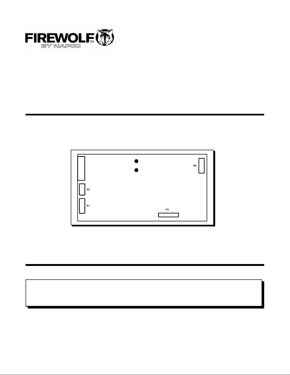
CONNECTIONS AND SETTINGS
FW-DACT MAIN BOARD:
There are no user configured jumpers on this Communicator.
P1 Ribbon Cable for connecting to NAPCO Fire Alarm Control Panel (FACP).
P2 RS-485 Connection for future expansion.
P4 Connector for FW-PCTOOL Configuration Module.
I2 Status Indicator LED for Telco Line #1; Red when the line is in use, Amber when there is a line fault.
I1 Status Indicator LED for Telco Line #2; Red when the line is in use, Amber when there is a line fault.
Page 4
Page 7

FIELD WIRING
FW-DACT MAIN BOARD TERMINAL CONNECTIONS:
Wire the two telephone lines devices to terminals as shown.
Line 1 Input (Tip/Ring): To the first Telephone Line via the required RJ31X Connector.
Line 1 Output (Tip/Ring): To an optional Premise Telephone on the first Telephone Line via the required RJ31X Connector.
Line 2 Input (Tip/Ring): To the second Telephone Line via the required RJ31X Connector.
Line 3 Output (Tip/Ring): To an optional Premise Telephone on the second Telephone Line via the required RJ31X Connector.
Note that most AHJ’s do not allow the connection of Premise Telephones. See wiring tables and specifications for more information.
Page 5
Page 8

SYSTEM CONFIGURATION & OPERATION
The NAPCO Digital Communicator is configured by connecting the FW-PCTOOL Configuration Tool to P4 of the FWDACT Main Board. Once connected, if no text appears immediately on the LCD screen, hit any key on the numeric
keypad.
The DACT supports three levels of restricted access to the Configuration Mode which allows for parameter
configuration and control of operation. Each level is associated with a separate Passcode (up to 8-digit numeric code)
and may be individually modified. Once a user gains access to the Configuration Mode, they are presented with a menu
of selections according to the level of access granted. The factory default Passcodes are:
Level I - OPERATOR “11111111”
Level II - INSTALLER “22222222”
A Restore-to-Factory-Defaults can be initiated from the FW-PCTOOL without having to first access program mode,
by using the special Passcode ...
Restore-to-Factory-Defaults “12345678”
Items accessible to Level(s) I and II
ITEM Access Menu Menu Label Description
Number Level Category
00 I, II Access Control Logout of DACT Exit from PROGRAM mode on LCD/Keypad.
01 I, II Access Control About DACT Display copyright (company and date) and firmware version
information on LCD.
02 I, II Access Control Change Passcode Support modification to specific passcode associated with
individual level.
10 I, II Event Logging Flush all events Terminate any in-progress event reporting.
Remove “report pending” trigger (i.e. cancel attempts to report
queued events) and
Force event queue (FIFO) to empty state (i.e. erase any queued
event history).
11 I, II Event Logging Send Test-Report Immediately initiate test-report generated to Account #1.
12 I, II Event Logging Abort-Reporting Terminate any in-progress event reporting.
Remove “report pending” trigger (i.e. cancel attempts to report
queued events).
NOTE: Unreported events are still resident within FIFO. Any
future events logged will restart attempts at reporting ALL
queued (unreported) event items. This action will also add a
“Line (x) Trouble” event to the event queue.
13 I, II Event Logging AC-Power Loss Specify an (optional) delay time (in hours), from 00 (no delay) to
(delay) 20 (maximum delay). A report of the “AC-Power Loss” event will
be delayed by this value, and then only sent after the period has
expired with the signal still present. A “restoral” event of this
signal will be reported immediately, but only if a prior “off-normal”
event was successfully reported earlier.
20 I, II Real Time Set System DATE Assign local DATE (dd/mm/yy) to DACT Real-Time-Clock device.
Clock The Year field will be presented in 4-digit format on LCD status
Parameters line, with automatic 20/21 century adjustment for Y2K
compliance.
21 I, II Real Time Set System TIME Assign local TIME (ss/mm/hh) to DACT Real-Time-Clock device.
Clock The Hour field will be presented in 24-hour (military) format on
Parameters LCD status line.
Page 6
Page 9

22 I, II Real Time Auto-Report Time Assign time (mm/hh) for DACT to perform periodic (24 hr
Clock intervals) Test-report generation to monitoring station .
Parameters
Page 7
Page 10

Items accessible to LevelII only
ITEM Access Menu Menu Label Description
Number Level Category
30 II Account (#1) Account ID #1 Assign 4-6 numeric Account ID to be identified with Account #1
monitoring station receiver.
31 II Account (#1) Dial-Prefix #1 (OPTIONAL) Set up-to-8-digits to be first dialed by DACT when
attempting to call Account #1 monitoring station receiver.
32 II Account (#1) Local Number #1 Set up-to-8-digits to be dialed (after Dial-Prefix #1 digits) by
DACT when attempting to call Account #1 monitoring station
receiver.
33 II Account (#1) Report Format #1 Choose report format (Contact ID or SIA) to be generated by
DACT when reporting with Account #1 monitoring station
receiver.
40 II Account (#2) Account ID #2 Assign 4-6 numeric Account ID to be identified with Account #1
monitoring station receiver
41 II Account (#2) Dial-Prefix #2 (OPTIONAL) Set up-to-8-digits to be first dialed by DACT when
attempting to call Account #2 monitoring station receiver.
42 II Account (#2) Local Number #2 Set up-to-8-digits to be dialed (after Dial-Prefix #2 digits) by
DACT when attempting to call Account #2 monitoring station
receiver.
43 II Account (#2) Report Format #2 Choose report format (Contact ID or SIA) to be generated by
DACT when reporting with Account #2 monitoring station
receiver.
50 II Report Priority ALARM Events Choose which Account # (1 or 2) will be the first to be
attempted to be reached by the DACT, when an ALARM event is
to be reported. This is designated as the “primary” account and
the other will become the “secondary”. If the DACT cannot
report to the primary, it will then attempt to report to the
secondary. This cycle will normally continue until the event is
eventually or the <MAXIMUM Attempts> has been achieved.
51 II Report Priority TROUBLE Events Choose which Account # (1 or 2) will be the first to be
attempted to be reached by the DACT, when a TROUBLE event
is to be reported. (See ITEM 50 for a description of the DACT
report-attempt operation).
52 II Report Priority SUPERVISORY Choose which Account # (1 or 2) will be the first to be
Events attempted to be reached by the DACT, when a SUPERVISORY
event is to be reported. (See ITEM 50 for a description of the
DACT report-attempt operation).
53 II Report Priority ‘Must’ Report #1 The selection allows the overriding of the “normal’ reporting
fulfillment strategy. If ‘Must’ Report #1 is ALWAYS, the DACT will
continue to attempt to report each event to Account #1 until
successful. This will be the case even if the event has been
previously reported to Account #2, and even if the DACT has
also exceeded MAX attempts. (see ITEM 55).
54 II Report Priority ‘Must’ Report #2 The selection allows the overriding of the “normal’ reporting
fulfillment strategy. If ‘Must’ Report #2 is ALWAYS, the DACT will
continue to attempt to report each event to Account #2 until
successful. This will be the case even if the event has been
previously reported to Account #1, and even if the DACT has
also exceeded MAX attempts. (see ITEM 55).
55 II Report Priority Max. Attempts Set the “normal” upper limit for DACT attempts (call-attempt
pairs) to report to monitoring station receivers.(See ITEM 50 for a
description of the DACT report-attempt operation). After this
count has been exceed, the DACT will assert the TROUBLESEND signal (and BUZZER) to the connected Fire-Panel.
60 II Phone Line Dial-type Line 1 Configure Line 1 for DTMF (Tone) or Rotary (Pulse) dialing. The
(1/2) choice of which line to be used when the DACT is reporting
normally alternates between Line 1/2 with each call-attempt.
61 II Phone Line Dial-type Line 2 Configure Line 2 for DTMF (Tone) or Rotary (Pulse) dialing. The
(1/2) choice of which line to be used when the DACT is reporting
normally alternates between Line 1/2 with each call-attempt.
Page 8
Page 11

NOTE: All items to be configured have default values assigned by the “Restore-to-Default” operation. All items must have
a (non-zero) value assigned unless specifically identified as OPTIONAL within the table(s) above.
REPORTING FORMATS
ADEMCO CONTACT-ID
DACT Internal Events (All Models):
Event Description Event Family Qualifier Code Group # Contact #
Phone Line #1 trouble detected Trouble New event 351 00 000
Phone Line #2 trouble detected Trouble New event 352 00 000
Phone Line #1 trouble restored Trouble Restore 351 00 000
Phone Line #2 trouble restored Trouble Restore 352 00 000
Failure to report to an Account Trouble New event 354 Acct # Acct #
Report to an Account successful Trouble Restore 354 Acct # Acct #
Periodic (24 hr) Test Event (All Normal) Test New event 602 00 000
Periodic (24 hr) Test Event (Off Normal) Test New event 608 00 000
Manually initiated dialer test Test New event 601 00 000
DACT External Events (FW-DACT):
Event Description Event Family Qualifier Code Group # Contact #
Fire Alarm Alarm New event 110 00 000
Fire Alarm restored Alarm Restore 110 00 000
System Trouble detected Trouble New event 300 00 000
System Trouble restored Trouble Restore 300 00 000
Supervisory condition Supervisory New event 200 00 000
Supervisory restored Supervisory Restore 200 00 000
SECURITY INDUSTRIES ASSOC. SIA-DCS
DACT Internal Events :
Event Description Event Family Qualifier SIA Event Code Parameter
Phone Line #1 trouble detected Trouble New event LT Line #
Phone Line #2 trouble detected Trouble New event LT Line #
Phone Line #1 trouble restored Trouble Restore LR Line #
Phone Line #2 trouble restored Trouble Restore LR Line #
Failure to report to an Account Trouble New event RT Acct #
Report to an Account successful Trouble Restore YK Acct #
Periodic (24 hr) Test Event (All Normal) Test New event RP 00
Page 9
Page 12

Periodic (24 hr) Test Event (Off Normal) Test New event RP 01
Manually initiated dialer test Test New event RX 00
DACT External Events (FW-DACT):
Event Description Event Family Qualifier SIA Event Code Parameter
Fire Alarm Alarm New event FA 00
Fire Alarm restored Alarm Restore FH 00
System Trouble detected Trouble New event FT 00
System Trouble restored Trouble Restore FJ 00
Supervisory condition Supervisory New event SS 00
Supervisory restored Supervisory Restore SR 00
COMPATIBLE FIRE ALARM CONTROL PANELS
NAPCO FW-DACT: Compatible with NAPCO FW-C2Z, FW-C4Z, FW-C4EZ Fire Alarm Control Panels.
COMPATIBLE RECEIVERS
The NAPCO FW-DACT is compatible with the following Digital Alarm Communicator Receivers (DACR) ...
DACR Receiver Model Protocols
SurGard MLR2 Multi-Line Receiver (ULC, ULI Approved) SIA-DCS and Ademco Contact ID
Osborne-Hoffman Quickalert! II Receiver (ULI Approved) SIA-DCS and Ademco Contact ID
Osborne-Hoffman OH-2000 Receiver (ULI Approved) SIA-DCS and Ademco Contact ID
Page 10
Page 13

Page 11
Page 14

SPECIFICATIONS
All Circuits are Power Limited
FW-DACT Digital Communicator:
M Connects to two Telephone Lines and performs both DC and Dial Tone Supervision.
M Connects to a NAPCO FACP via a ribbon cable. This connection provides DC power and all signalling between the
Communicator and the FACP.
M Transmits Common Alarm, Supervisory, and Trouble status to a Central Monitoring Station, using either Ademco
Contact ID or SIA DCS Protocols.
M User configured using the FW-PCTOOL Configuration Tool, with three levels of Password control.
M Current Consumption: Standby: See compatible Fire Alarm Control Panel - Installation and Operation Manual.
BATTERY CALCULATIONS
FW-DACT:
The FW-DACT Battery Calculations are performed as part of the calculations for the Fire Alarm Control Panel it will be
used in. See the appropriate NAPCO Installation and Operation Manual.
Page 12
Page 15

WARRANTY
NAPCO SECURITY SYSTEMS, INC. (NAPCO) by others, improperly used, abused, altered, damaged,
warrants its products to be free from manufacturing subjected to accident, nuisance, flood, fire or acts of
defects in materials and workmanship for 12 months God, or on which any serial numbers have been altered,
following the date of manufacture. NAPCO will, within defaced or removed. NAPCO will not be responsible for
said period, at its option, repair or replace any product any dismantling, reassembly or reinstallation charges.
failing to operate correctly without charge to the original
purchaser or user. This warranty contains the entire warranty. It is the
sole warranty and any prior agreements or
This warranty shall not apply to any equipment, or any representations, whether oral or written, are either
part thereof, which has been repaired by others, merged herein or are expressly cancelled. NAPCO
improperly installed, improperly used, abused, altered, neither assumes, nor authorizes any other person
damaged, subjected to acts of God, or on which any purporting to act on its behalf to modify, to change, or
serial numbers have been altered, defaced or removed. to assume for it, any other warranty or liability
Seller will not be responsible for any dismantling or concerning its products.
reinstallation charges.
In no event shall NAPCO be liable for an amount in
THERE ARE NO WARRANTIES, EXPRESS OR excess of NAPCO’s original selling price of the product,
IMPLIED, WHICH EXTEND BEYOND THE for any loss or damage, whether direct, indirect,
DESCRIPTION ON THE FACE HEREOF. THERE IS incidental, consequential, or otherwise arising out of
NO EXPRESS OR IMPLIED WARRANTY OF any failure of the product. Seller’s warranty, was herein
MERCHANTABILITY OR A WARRANTY OF FITNESS above set forth, shall not be enlarged, diminished or
FOR A PARTICULAR PURPOSE. ADDITIONALLY, affected by and no obligation or liability shall arise or
THIS WARRANTY IS IN LIEU OF ALL OTHER grow out of Seller’s rendering of technical advice or
OBLIGATIONS OR LIABILITIES ON THE PART OF service in connection with Buyer’s order of the goods
NAPCO. furnished hereunder.
Any action for breach of warranty, including but not NAPCO RECOMMENDS THAT THE ENTIRE SYSTEM
limited to any implied warranty of merchantability, must BE COMPLETELY TESTED WEEKLY.
be brought within the six months following the end of
the warranty period. Warning: Despite frequent testing, and due to, but not
limited to, any or all of the following; criminal tampering,
IN NO CASE SHALL NAPCO BE LIABLE TO ANYONE electrical or communications disruption, it is possible
FOR ANY CONSEQUENTIAL OR INCIDENTAL for the system to fail to perform as expected. NAPCO
DAMAGES FOR BREACH OF THIS OR ANY OTHER does not represent that the product/system may not be
WARRANTY, EXPRESS OR IMPLIED, EVEN IF THE compromised or circumvented; or that the product or
LOSS OR DAMAGE IS CAUSED BY THE SELLER’S system will prevent any personal injury or property loss
OWN NEGLIGENCE OR FAULT. by burglary, robbery, fire or otherwise; nor that the
product or system will in all cases provide adequate
In case of defect, contact the security professional who warning or protection. A properly installed and
installed and maintains your security system. In order maintained alarm may only reduce risk of burglary,
to exercise the warranty, the product must be returned robbery, fire or otherwise but it is not insurance or a
by the security professional, shipping costs prepaid and guarantee that these events will not occur.
insured to NAPCO. After repair or replacement, CONSEQUENTLY, SELLER SHALL HAVE NO
NAPCO assumes the cost of returning products under LIABILITY FOR ANY PERSONAL INJURY, PROPERTY
warranty. NAPCO shall have no obligation under this DAMAGE, OR OTHER LOSS BASED ON A CLAIM
warranty, or otherwise, if the product has been repaired THE PRODUCT FAILED TO GIVE WARNING.
Page 13
Page 16

Therefore, the installer should in turn advise the implied warranty lasts or do not allow the exclusions or
consumer to take any and all precautions for his or her limitation of incidental or consequential damages, or
safety including, but not limited to, fleeing the premises differentiate in their treatment of limitations of liability for
and calling police or fire department, in order to mitigate ordinary or gross negligence, so the above limitations
the possibilities of harm and/or damage. or exclusions may not apply to you. This warranty
gives you specific legal rights and you may also hav e
NAPCO is not an insurer of either the property or safety other rights which vary from state to state.
of the user’s family of employees, and limits its liability
for any loss or damage including incidental or
consequential damages to NAPCO’s original selling
price of the product regardless of the cause of such
loss or damage.
Some states do not allow limitations on how long an
Head Office:
FIREWOLF Advanced Fire Products
NAPCO Security Systems, Inc.
333 Bayview Avenue
AMITYVILLE, N.Y.
U.S.A. 11701
Phone: (516) 842-9400
IN NORTH AMERICA Phone: 1-800-645-9445
FAX Toll Free: (516) 789-9292
Web Page: http://www.napcosecurity.com
e-mail: techinfo@napcosecurity.com
Page 14
 Loading...