


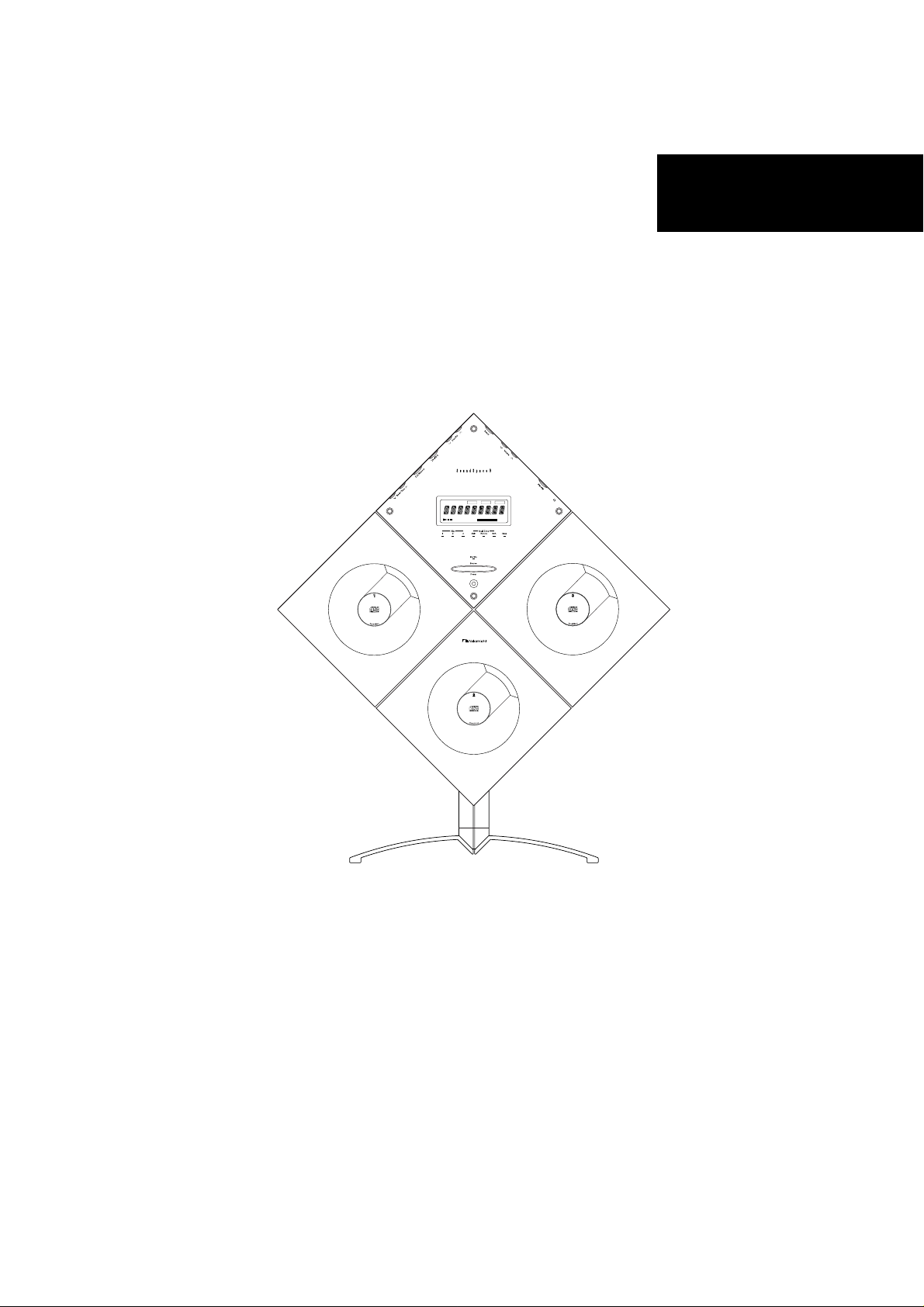
Soundspace 9
Table of contents
 Loading...
Service Manual
Service Manual
Stereo Music System
SoundSpace 9
SS-9 General
Random
Preset
FMAM
Disc Track RemainingTime
Memory Repeat
ST
Memory No.
Loud.Vol.
i
GENERAL
SS-9 General
1.1. Product Code
D210
Abbreviations for Destinations:
CAN — Canada CH — China
DA — South America
EP — Europe HK — Hong Kong
JPN — Japan KR — Korea
OTR — Other TW — Taiwan
UK — United Kingdom
USA — U.S.A. AUS — Australia
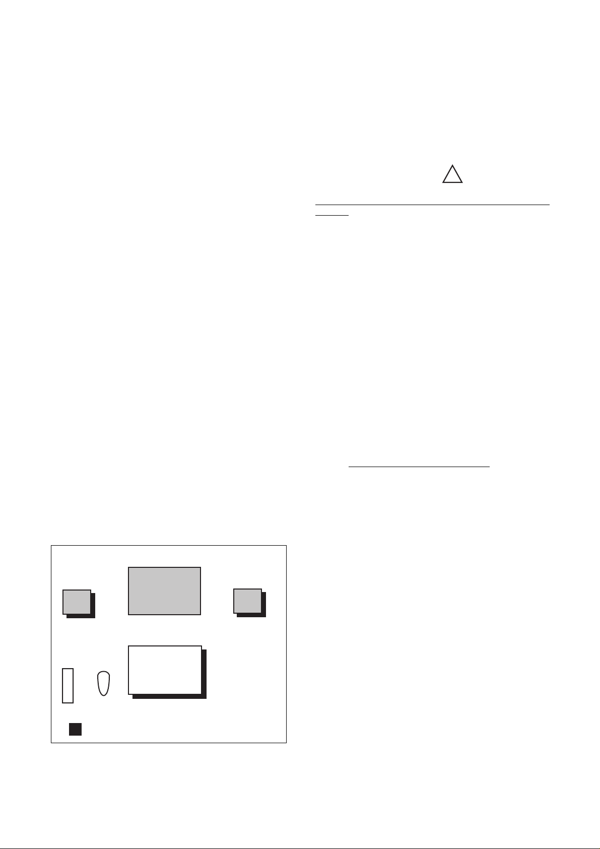
1.2. System Configuration
The SoundSpace consists of the following units.
●Main Unit (See pages 1-1, 1-2, ... in this manual)
Controls entire of the System. Mainly consists of the
following sections:
• Control section (including the system control microprocessor)
• Tuner section
• Operation panel control section
• CD player section (including the mechanism control microprocessor)-- 3 identical CD player sections (Interchangeable with each other except for
the Door Cap Ass'y on which the disc number is
written.)
● Subwoofer
(See pages 2-1, 2-2, ... in this manual)
• Subwoofer
• Power amp. section
• Power supply section
●Floor Stands (Option)
• Floor stand for Main Unit
• Floor stand for Satellite Speakers L/R
1.3. Cautions/Warnings
(1) Product Safety Notice
Parts marked with the symbol in the schematic
diagram have critical characteristics.
Use ONLY replacement parts recommended by the manufacturer. It is recommended that the unit be operated from a
suitable DC supply or batteries during initial check-out procedures.
(2) Leakage Current Check/Resistance Check
Before returning the unit to the customer, make sure you
make either (1) a leakage current check or (2) a line to
chassis resistance check. If the leakage current exceeds
0.5 milliamp, or if the resistance from chassis to either side
of the power cord is less than 240 k ohms, the unit is defective.
WARNING — DO NOT return the unit to the customer
until the problem is located and corrected.
(3) Protection of Eyes from Laser Beam
To protect eyes from invisible laser beam during servicing,
DO NOT LOOK AT THE LASER BEAM
(4) Laser Caution
CAUTION
Adjusting the knobs, switches, and controls, etc. or taking
actions not specified herein may result in a harmful emission of laser beams. This CD Player must be adjusted and
repaired
only by qualified service personnel.
!
on the Changer.
●Satellite Speakers L/R
(See pages 3-1, 3-2, ... in this manual)
●Main Remote Control/Sub Remote Control
Subwoofer
Speaker L
Remote Control
(Main) (Sub)
: Floor Stand (Option)
Fig. 1.1 SS-9 System Configuration
• Power Amp.
• Power Supply
Main Unit
• Tuner
• CD Player x 3
Speaker R
OBSERVERA!
Sådana inställningar av rattarna, omkopplarna eller övriga
kontrollknappar som inte är beskriva i bruksanvisningen
kan resultera i farlig laserutstrålning. Justering eller reparation av denna kompaktskivspelare skall endast utföras av
kvalificerad servicepersonal.
OBS!
Indstilling af knapper, cmskiftere og øvrige kontrolknapper,
som ikke følger den i brugsanvisningen beskrevne måde,
kan resultere i farlig laserudstråling. Justering eller reparation af denno CD-afspiller må kun udføres af kvalificeret
servicepersonale.
OBS!
Justering av ratt, brytere og kontroller andre enn de som er
beskrevet her, kan resultere i farlig laserbestråling. Justering eller reparasjon av denne kompaktdiskspilleren ma
bare utføres av kvalifiserte fagfolk.
HUOMAUTUS
Jos nuppeja, kytkimiä ja säätimiä ym, säädetään tai laitetta
käytetään toisella tavalla kuin on selostettu, tuloksena saattaa olla vaarallista lasersäteiden vuotoa. CD-soittimen
säätö ja korjaus on jätettävä aina asiantuntevan
huoltoteknikon tehtäväksi.
ii
SS-9 General
ADVERSEL: USYNLIG LASERSTRÅLING VED ÅBNING.
UNDGÅ UDSAETTELSE FOR STRÅLING.
VARO!: AVATTAESSA OLET ALTTIINA
NÄKYMÄTTÖMÄLLE LAS-
ERSÄTEILYLLE.
ÄLÄ KATSO SÄTEESEEN.
VARNING —OSYNLIG LASERSTRÅLNING NAR
DENNA DEL ÄR ÖPPNAD. BETRAKTA
EJ STRÅLEN.
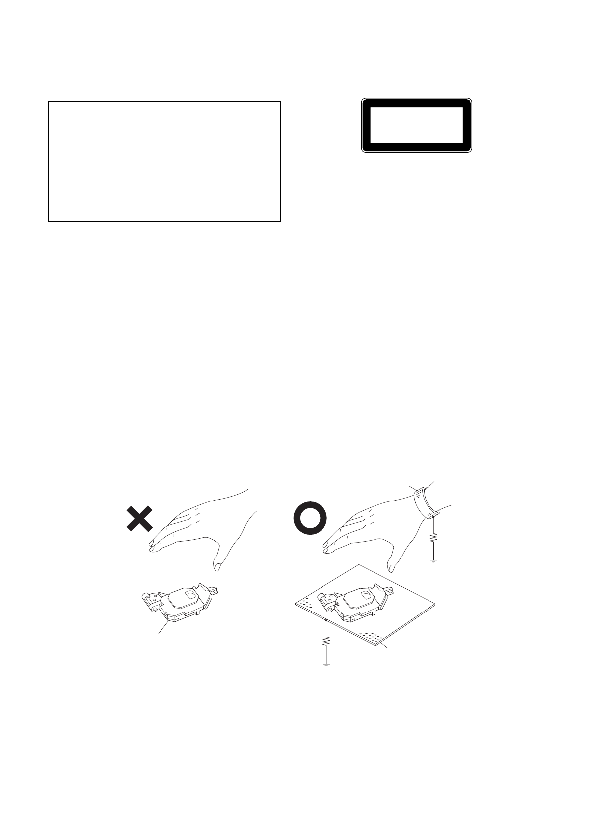
1.4. Handling the Laser Pickup
In case of repair or replacement of the Laser Pickup, pay
attention to the following handling instructions since the laser diode in the Laser Pickup is not resistant to static electricity.
(1) Grounding
When you repair a Laser Pickup, first ground the human body, as well as the measuring instruments and
other tools (with particular caution to soldering iron).
What's more, your workbench and floor should desirably be grounded using conductive sheet or copper
plate. See Fig. 1.2.
NOTE: Be careful so as not to let your clothes touch
the Laser Pickup, as static electricity on the
clothes will not be released even if your body
is grounded.
CLASS 1
LASER PRODUCT
THIS COMPACT DISC PLAYER IS CLASSIFIED
AS A CLASS 1 LASER PRODUCT.
THE CLASS 1 LASER PRODUCT LABEL IS
LOCATED ON THE REAR EXTERIOR.
(2) Discharge of Electricity
Be sure to discharge electricity from objects brought into
contact with the Laser Pickup (i.e., soldering iron, tweezers,
probes, volt-ohm-meter probes, etc.) before starting work
by contacting them with the body chassis. Besides, never
touch the Laser Pickup while power is applied.
(3) Soldering Iron to be Used
The soldering iron for use in repair work should be: (1) a
ceramic soldering iron, (2) a soldering iron with its metal
part grounded, or (3) a soldering iron whose insulation resistance after five minutes of power application is 10 M-ohm
or more at 500 VDC. Soldering should be completed
promptly, at a soldering iron temperature of 320° max (39
W). A soldering iron heated above this temperature can
break down the laser diode.
(NO GOOD)
Laser Pickup
Wrist-strap
for Grounding
(GOOD)
1MΩ
1MΩ
Conductive Sheet or
Copper Plate
Fig. 1.2 Handling the Laser Pickup
iii
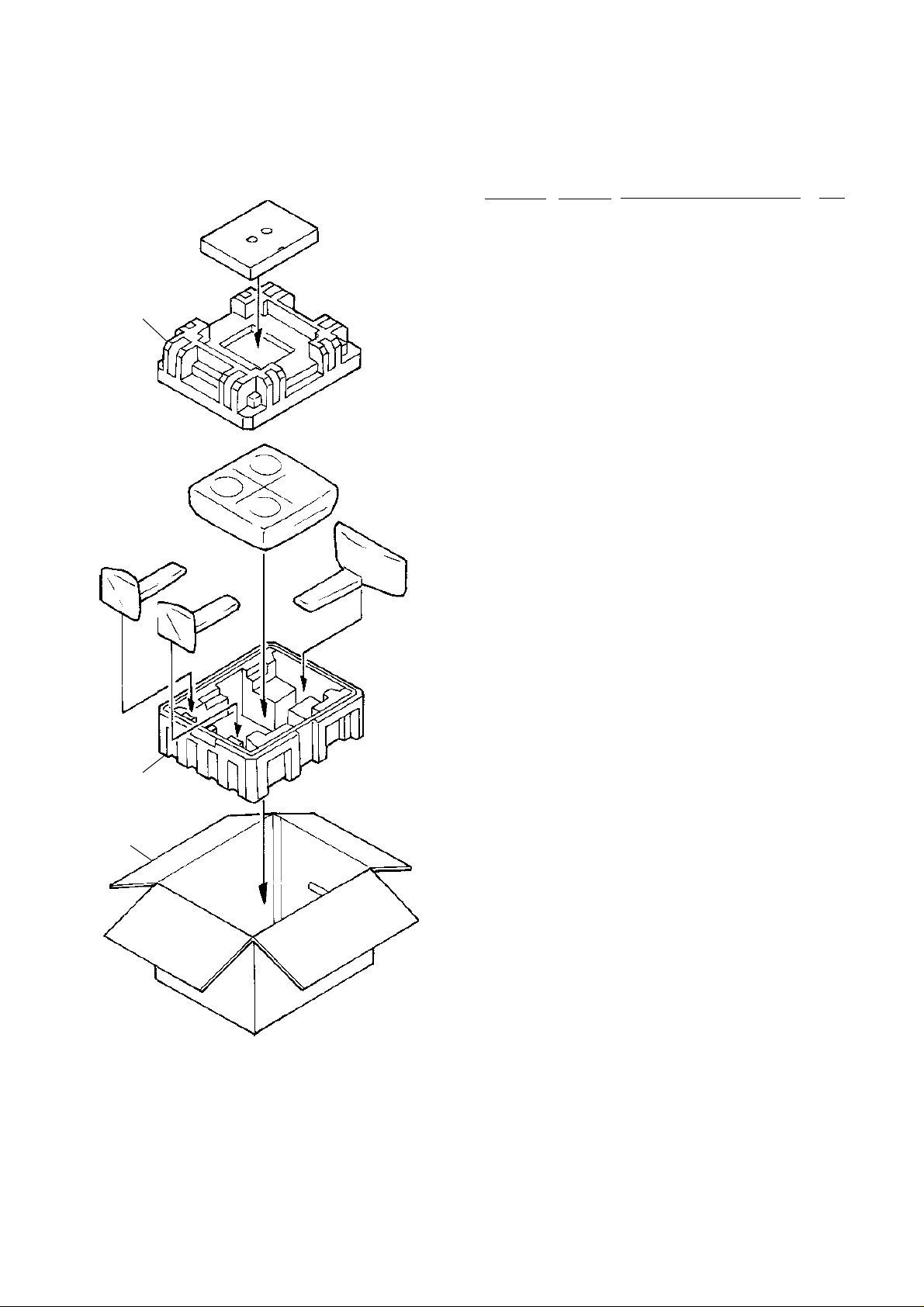
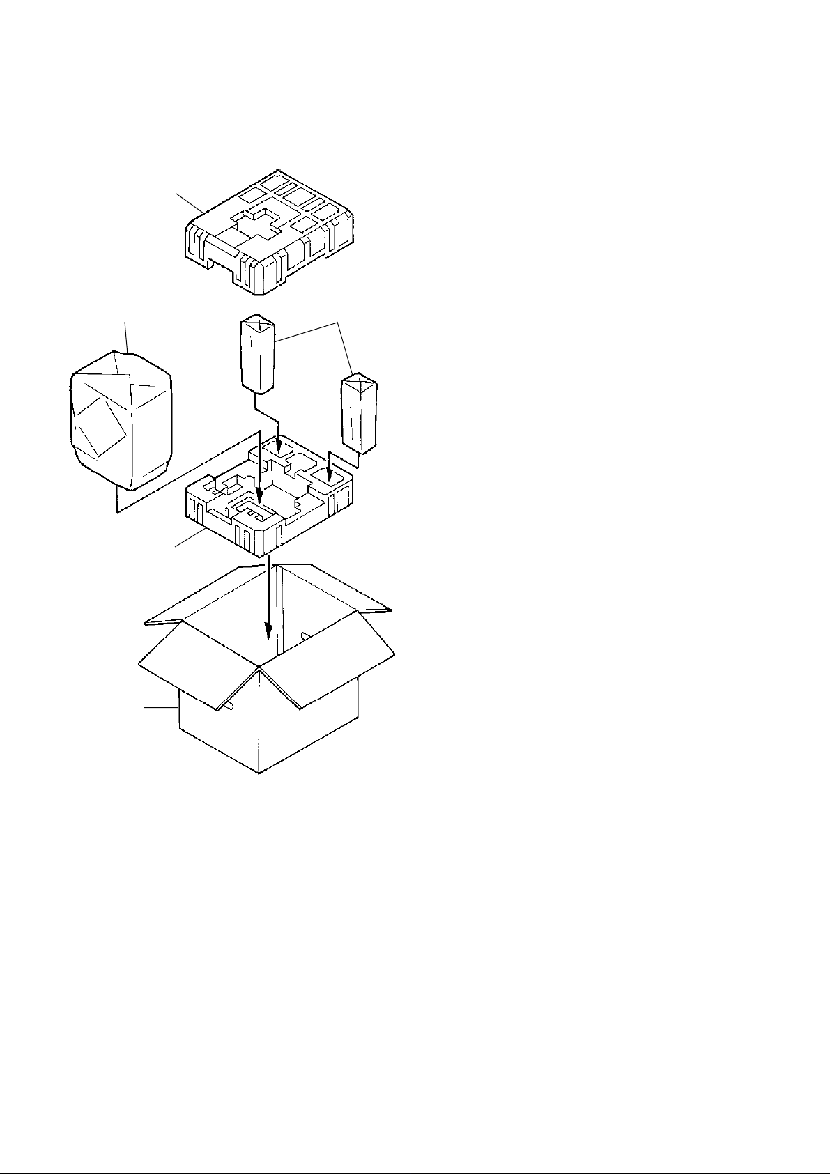
1.5. Package Ass’y and Accessory Ass’y
(1) Main Unit
03
02
01
SS-9 General
Schematic
Ref. No. Part No. Description Q'ty
— Package & Accessory Ass'y
(Main Unit)
01 0F05628A Carton Box 1
02 0F05630A Packing Bottom Center 1
03 0F05629A Packing Top Center 1
— 0F05631A Accessory Box 1
— 0F05689A Soft Sheet D Top A 1
— 0F05690A Soft Sheet D Top B 2
— 0F05692A Soft Bag Center 1
— 0F05693A Soft Bag Stand Top 3
— 0B85619A 13P DIN Cable 5m 1
— 0B85620A 3P RCA Cable 5m 1
— 0B90462A Battery UM4x1 4
— 0B90819A FM Indoor Antenna 1
— 0B90820A Antenna Adaptor 1
(JPN, OTR, USA, CAN, DA, TW)
— 0B91071A Antenna Adapter EP 1
(UK, AUS, EP, CH, HK, KR)
— 0D03092B Poly Bag 1
— 0D07105A Speaker Cable 2
— 0D07238A AC Cord UL (USA, CAN) 1
— 0D07239A AC Cord EP (EP) 1
— 0D07240A AC Cord DA/DU (OTR, DA, TW) 1
— 0D07241A AC Cord DM (JPN) 1
— 0D07242A AC Cord BS/HK (UK, HK) 1
— 0D07243A AC Cord CH (CH) 1
— 0D07244A AC Cord KR (KR) 1
— 0D07245A AC Cord SA (AUS) 1
— 0D07371B Owner’s Manual Japanese 1
— 0D07372B Owner’s Manual English 1
— 0D07375A Template 1
— 0D07376A Owner’s Manual Korean 1
— 0D07450A Owner’s Manual French 1
— 0D07451A Owner’s Manual German 1
— 0D07452B Owner’s Manual Spanish 1
— 0D07453A Owner’s Manual Italian 1
— 0D07454A Template Speaker 1
— 0D07477A AM Loop Antenna 1
— 0F05693A Soft Bag Stand Top 1
— 0H08216A CD Single Adaptor (JPN) 1
— 0H08749A Cable Holder 1
— 0H09008E Stand Holder Cover Center 1
— 0H09012A Stand Pole Cover L67 1
— 0H09013A Stand Pole Cover L82 2
— 0H09031A Base Cover Center DT 1
— 0J08862A Pole Cover Cushion 1
— DA05574A Screw Ass’y D210 1
— DG05310A Remote Control Sub Ass’y SS—5 1
— HA08444A Main Remote Ass’y SS9 1
(Except UK, EP)
— HA08447A Main Remote Ass’y RDS SS9 (UK, EP) 1
Fig. 1.3 Main Unit
iv
(2) Subwoofer and Satellite Speakers
03
04
SS-9 General
Schematic
Ref. No. Part No. Description Q'ty
— Package and Accessory Ass’y
(Subwoofer and Satellite Speakers)
01 0F05694A Carton Box S369 1
02 0F05703A Packing Bottom Subwoofer 1
03 0F05702A Packing Top Subwoofer 1
04 0F05691A Soft Sheet Subwoofer 1
05 0F05541A Soft Bag Satellite 2
— DA05647A Screw Ass’y S369 1
— DA05648A Spacer Ass’y S369 1
05
02
01
Fig. 1.4 Subwoofer and Satellite Speakers
v
Main Unit Section
Memory Repeat
Random
ST
Preset
FMAM
Disc Track RemainingTime
Memory No.
Loud.Vol.
SS-9 Main Unit Section
Main Unit
1-1

SS-9 Main Unit Section
CONTENTS
1. REMOVAL PROCEDURES ................................................................................................................................1-3
1.1. Rear Cover.............................................................................................................................................1-3
1.2. Main P.C.B. Ass'y ..................................................................................................................................1-3
1.3. Mechanism CD Ass'y .............................................................................................................................1-3
1.4. Front P.C.B. Ass'y ..................................................................................................................................1-4
1.5. Mechanism Chassis Block/Door Block of the Mechanism CD Ass'y ....................................................1-4
1.6. Disc Loading Ass'y .................................................................................................................................1-4
1.7. CD P.C.B. Ass'y and Traverse Mecha Ass'y .........................................................................................1-5
1.8. Laser Pickup ..........................................................................................................................................1-6
1.9. Sled Motor ..............................................................................................................................................1-6
2. ELECTRICAL CHECKS ..................................................................................................................................... 1-8
2.1. Measurement Instruments and Jigs ......................................................................................................1-8
2.2. Parts Location for Electrical Check........................................................................................................1-8
2.3. Electrical checks for CD Player .............................................................................................................1-9
3. MECHANISM ASS'Y AND PARTS LIST ...........................................................................................................1-11
3.1. Main Stand Ass'y ......................................................................................................... ..........................1-11
3.2. Synthesis (Main Unit) .............................................................................................................................1-12
3.3. Mechanism CD Ass'y 1/Mechanism CD Ass'y 2 (A01) .........................................................................1-14
3.4. Mechanism Chassis Ass'y (B01) ...........................................................................................................1-16
3.5. Traverse Mecha Ass'y (B02)..................................................................................................................1-17
3.6. Disc Loading Ass'y (B03) ....................................................................................................................... 1-18
4. ELECTRICAL PARTS LIST ...............................................................................................................................1-20
4.1. Main P.C.B. Ass'y......................................................................................................................................1-20
4.2. Front P.C.B. Ass'y .....................................................................................................................................1-20
4.3. CD P.C.B. Ass'y ........................................................................................................................................1-21
4.4. LED P.C.B. Ass'y ......................................................................................................................................1-21
4.5. SEN LD1 P.C.B. Ass'y ..............................................................................................................................1-21
4.6. SEN LD2 P.C.B. Ass'y ..............................................................................................................................1-21
4.7. SEN UD P.C.B. Ass'y ................................................................................................................................1-21
5. IC BLOCK DIAGRAMS .....................................................................................................................................1-22
6. BLOCK DIAGRAM ............................................................................................................................................1-33
SPECIFICATIONS (See the end of this manual.)
SCHEMATIC DIAGRAMS AND MOUNTING DIAGRAMS (See the separate volume.)
1-2
SS-9 Main Unit Section
1. REMOVAL PROCEDURES
NOTE: When parts required lubrication are replaced or reassembled, apply specified lubricant to the parts.
For the parts which require lubrication, refer to 3. "MECHANISM ASS'Y AND PARTS LIST."
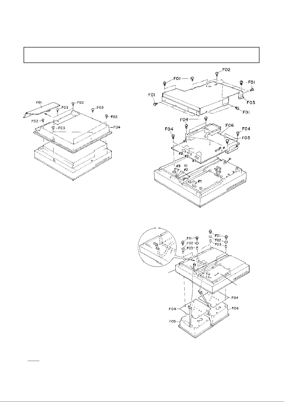
1.1. Rear Cover
Refer to Fig. 1.1.
(1) Remove F01 (Main Jack Cover) by pulling it out.
(2) Remove screws F02 (ST3x8 + Binding (Black), 5 pcs.)
and F03 (PT3x10 + Trass, 4 pcs.), and detach F04
(Rear Cover) from the main body.
Main P.C.B. Ass'y
Rear Cover
Fig. 1.1
1.2. Main P.C.B. Ass'y
Refer to Fig. 1.2.
(1) Remove the Rear Cover. Refer to item 1.1.
(2) Remove screws F01 (ST3x4 + Binding, 15 pcs.) and
F02 (M2.6x4 + Binding, 2 pcs.), and detach F03.
(3) Remove screws F04 (ST3x5 + Binding, 10 pcs.) and
F05 (ST2.6x4 + Binding, 2 pcs.), and detach F06
(Main P.C.B. Ass'y).
Notes on reassembling:
• Connect the cables #1, #2 and #3 to the connectors #1,
#2 and #3 on the Main P.C.B. Ass'y, respectively.
1.3. Mechanism CD Ass'y
Refer to Fig. 1.3.
(1) Remove the Main P.C.B. Ass'y. Refer to item 1.2.
(2) Remove screws F01 (M3x8 + Binding (2A), 8 pcs.),
F02 (Damper Collar, 8 pcs.) and F03 (Mecha Damper,
8 pcs.).
(3) Lift the Escutcheon and remove F04 (2 pcs.) from F05
(Mechanism CD Ass'y 1-No. 2) and F06 (Mechanism
CD Ass'y 1-No. 3).
Note: The Mechanism CD Ass'y 2-No. 1 can be removed
in the same way.
Notes on reassembling:
• When assembling the Mechanism CD Ass'y 1-No. 3, with
the Mechanism CD Ass'y 1-No. 2 not assembled yet,
pass the cable of the Mechanism CD Ass'y 1-No. 3 over
the frame "A". Otherwise, you cannot assemble the
Mechanism CD Ass'y 1-No. 3.
• Pass the cables of each Mechanism CD Ass'y through
the holes "B" and "C" as shown in Fig. 1.3. For Mechanism CD Ass'y 1-No. 2/No.3, extend their cables approx.
10 cm.
Escutcheon
Mechanism
CD Ass'y 1
-No.2
Fig. 1.2
A
B
C
Mechanism
CD Ass'y 2
-No. 1
Mechanism
CD Ass'y 1
-No. 3
Fig. 1.3
1-3
SS-9 Main Unit Section
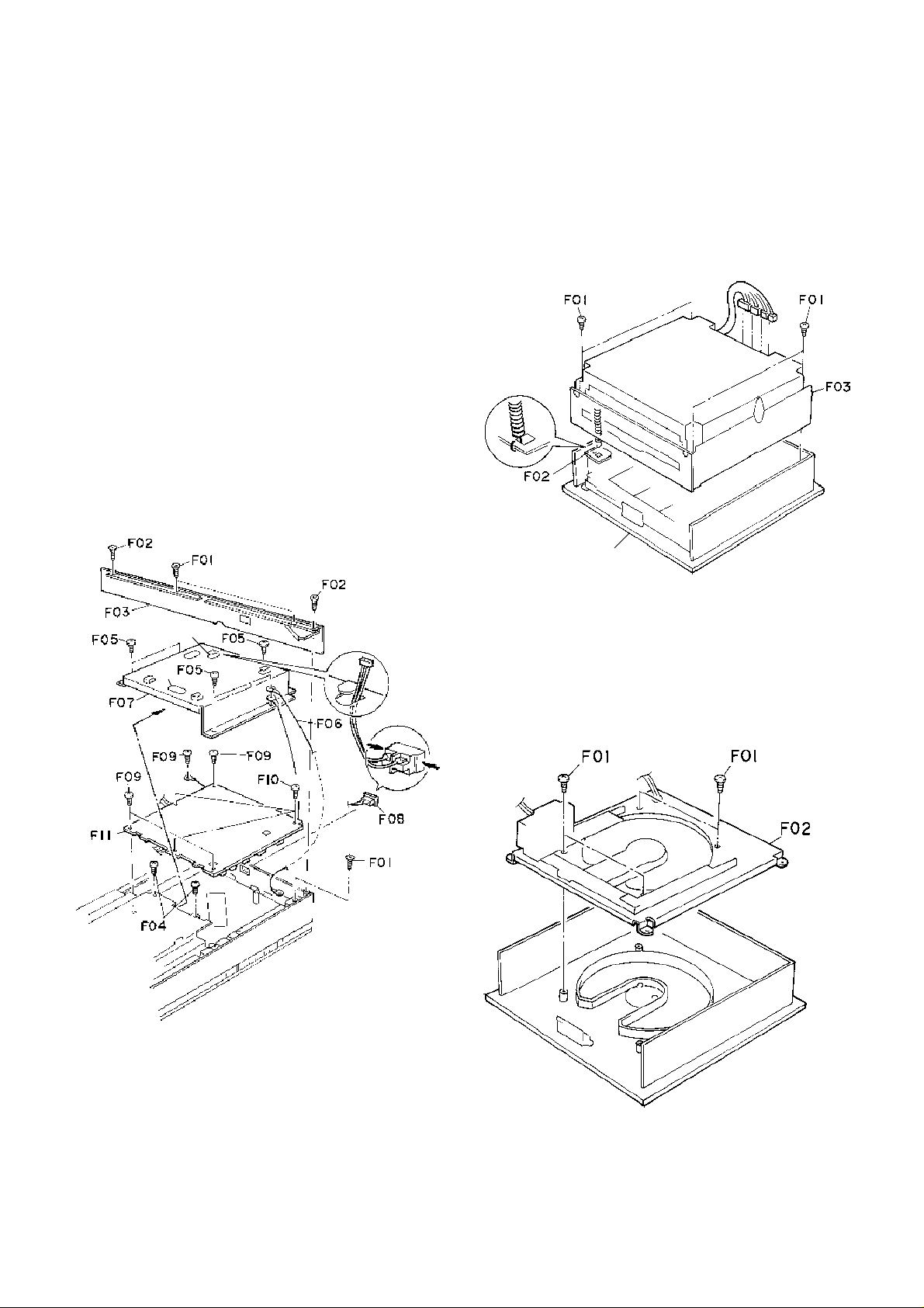
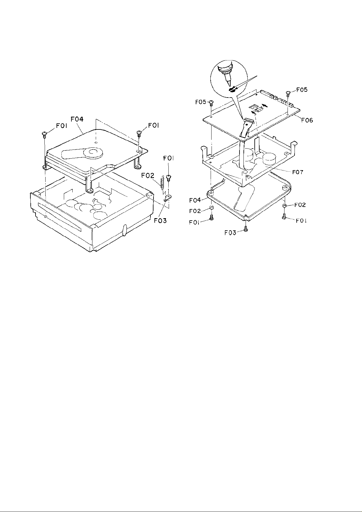
1.4. Front P.C.B. Ass'y
Refer to Fig. 1.4.
(1) Remove the Mechanism CD Ass'y. Refer to item 1.3.
(2) Remove screws F01 (BT2.6x6 + Flat Head, 2 pcs.)
and F02 (PT2.6x8 + Flat Head, 2 pcs.), and detach
F03 (Dress Plate Side C/D).
(3) Remove screws F04 (2 pcs.) and F05 (PT3x8 + Bind-
ing, 5 pcs.), and detach F06 (GND Wire Ass'y).
(4) Remove F07 in the direction shown by the arrow while
passing the power switch cable through the hole "A"
and 3 connectors through the hole "B".
(5) Remove F08 (Power Switch) outward while pinching
its claws inward.
(6) Remove screws F09 (PT3x5 + Binding, 4 pcs.) and
F10 (PT3x8 + Binding, 3 pcs.), and detach F11 (Front
P.C.B. Ass’y).
Notes on reassembling:
• When assembling F08 (Power Switch), be careful so as
not to assemble it upside down.
• When assembling F07, pass the power switch cable
through the hole "A" and 3 cables through the hole "B".
1.5. Mechanism Chassis Block/Door Block of the
Mechanism CD Ass'y
Refer to Fig. 1.5.
(1) Remove the Mechanism CD Ass'y. Refer to item 1.3.
(2) Remove screws F01 (M2.6x5 + Binding, 4 pcs.), un-
hook the spring F02, and detach F03 (Mechanism
Chassis Block) from the Door Block.
Mechanism Chassis
Block
Door Block
Fig. 1.5
Front
P.C.B.
Ass’y
A
1.6. Disc Loading Ass'y
Refer to Fig. 1.6.
B
(1) Remove the Door Block of the Mechanism CD Ass'y.
Refer to item 1.5.
(2) Remove screws F01 (PT2.6x6 + Binding (Black), 4
pcs.), and detach F02 (Disc Loading Ass'y).
Disc Loading Ass'y
Fig. 1.4
1-4
Fig. 1.6
1.7. CD P.C.B. Ass'y and Traverse Mecha Ass'y
Refer to Figs. 1.7.1 and 1.7.2.
(1) Remove the Mechanism Chassis Block. Refer to item
1.5.
(2) Remove screws F01 (M3x5 + Binding (Black), 4 pcs.),
F02 (Stabi SP) and F03, and detach F04 (Traverse
Mechanism Block). Refer to Fig. 1.7.1.
Traverse Mechanism Block
SS-9 Main Unit Section
Laser diode shorting lands
CD P.C.B. Ass’y
Traverse Mecha
Ass’y
Fig. 1.7.1
(3) Remove screws F01 (M2.6x4 + Binding (Black), 3
pcs.), collars F02 (3 pcs.) and one screw F03 (M2.6x4
+ Pan (Black)), and detach F04 (Traverse Cover CD).
Refer to Fig. 1.7.2.
(4) Short the laser diode shorting lands with a soldering
iron.
Note: Use the soldering iron whose metal part is
grounded or a ceramic soldering iron.
CAUTION: Do not disconnect the Flexible Cable from
the CD P.C.B. Ass'y unless the laser shorting lands are shorted.
(5) Remove screws F05 (M3x5 + Binding), 4 pcs.) and de-
tach F06 (CD P.C.B. Ass’y).
(6) Remove three Damper Screw SL and one Damper
Screw SD, and detach F07 (Traverse Mecha Ass'y).
Notes on reassembling:
• Unsolder the laser diode shorting lands after reassembling the CD P.C.B. Ass'y.
Fig. 1.7.2
1-5
SS-9 Main Unit Section
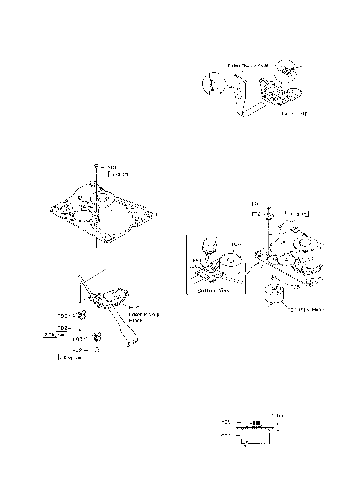
1.8. Laser Pickup
1.8.1. Removing the Laser Pickup
Refer to Fig. 1.8.1.
(1) Remove the Traverse Mecha Ass'y. Refer to item 1.7.
(2) Remove screws F01 (M1.7x4 + Pan, 2 pcs.) and F02
(M2.6x3.5 + Pan, 2 pcs.), and F03 (4 pcs.), and disassemble F04 (Laser Pickup Block).
(3) Pull out the PU Guide Shaft SL from the Laser Pickup
Block.
(4) Before disconnecting the Pickup Flexible P.C.B. from
the Laser Pickup, short the laser diode shorting lands
on the bottom of the Laser Pickup. Refer to Fig. 1.8.2.
NOTE: Use the soldering iron whose metal part is
grounded or a ceramic soldering iron.
(5) Disconnect the Pickup Flexible P.C.B. from the Laser
Pickup.
Short
Already shorted.
(See Fig. 1.7.2)
Fig. 1.8.2
1.9. Sled Motor
1.9.1. Removing the Sled Motor
Refer to Fig. 1.9.1.
(1) Remove the Traverse Mecha Ass'y. Refer to item 1.7.
(2) Remove a cut washer F01 and pull out F02 (Second
Gear).
(3) Remove screws F03 (M1.7x2.5 + Pan #0 Type 3
(Black), 2 pcs.) and detach the Sled Motor Block.
(4) Remove F05 (First Gear) from F04 (Sled Motor).
(5) Unsolder the wires of F04 (Sled Motor) from the Tra-
verse P.C.B. Ass'y.
PU Guide Shaft SL
✪: Apply lubricant
G-4270.
✪
Fig. 1.8.1
1.8.2. Installing a New Laser Pickup
(1) Connect the Pickup Flexible P.C.B. to the new Laser
Pickup. Refer to Fig. 1.8.2.
(2) Open the laser diode shorting lands on the bottom of
the Laser Pickup.
NOTE: Use the soldering iron whose metal part is
grounded or a ceramic soldering iron.
(3) Insert the PU Guide Shaft SL into the Laser Pickup.
(4) Assemble F04 (Laser Pickup Block) with F03 ( 4 pcs.)
by tightening screws F02 (2 pcs.) with a torque of 3.0
kg-cm.
(5) Assemble F04 (Laser Pickup Block) with screws F01
(2 pcs.) with a torque of 1.2 kg-cm. Refer to Fig. 1.8.1.
✪
✪: Apply lubricant
G-4270.
Fig. 1.9.1
1.9.2. Installing a New Sled Motor
(1) Reassemble F04 (Sled Motor) with screws F03 (2
pcs.) with a torque of 2.0 kg-cm.
NOTE: Pay attention to the sled motor installing di-
rection. Install it as shown in Fig. 1.9.1.
(2) Press fit a new F05 (First Gear) so that the gap be-
tween the chassis surface and the bottom of F05 (First
Gear) is 0.1 mm as shown in Fig. 1.9.2.
(3) Solder the wires of F04 (Sled Motor) to the Traverse
P.C.B. Ass'y.
(4) Reassemble other removed parts by reversing the re-
moval procedure.
Fig. 1.9.2
1-6
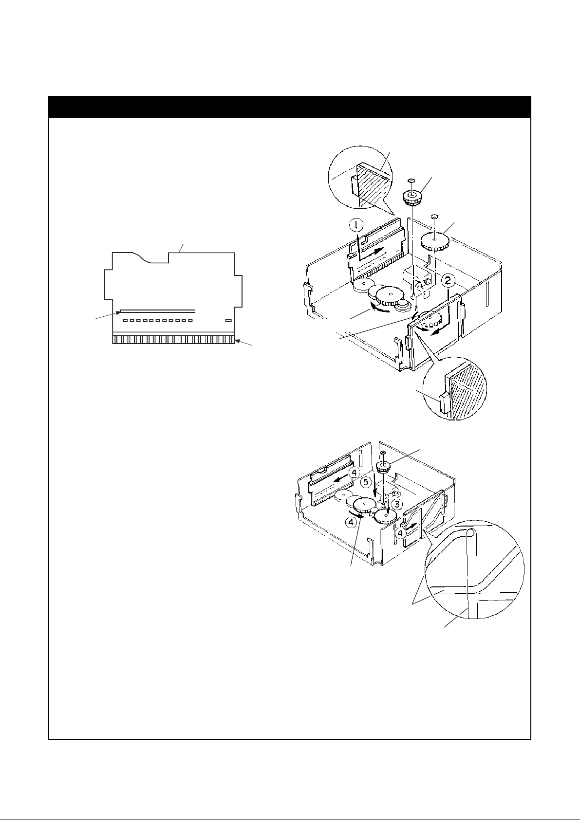
How to reassemble the UD Cam S and UD Cam
How to identify the UD Cam S and UD Cam:
The UD Cam S is used on the left side of the CD Mechanism Ass'y in Fig. A. It has the projections as shown below:
While, the UD Cam is used on the right side of the CD
Mechanism Ass'y in Fig. A, and has not projections.
• Note that they move in the opposite direction each
other. For example, in Fig. A, when the UD Cam S
moves backwards, the UD Cam moves forward.
UD Cam S
SS-9 Main Unit Section
UD Cam S
Cam D WW Guide
Cam D L Gear
Projection
Rack
(1) Remove the cut washer and pull out the Cam D WW
Gear. Refer to Fig. A.
(2) Remove the cut washer and pull out the Cam D L
Gear. (Thus, the link between the UD Cam S and UD
Cam is lost.)
(3) Assemble the UD Cam S on the chassis so that its
rack engages with the gear on the chassis. Then, by
turning the Cam D L Gear on the chassis, align the
edge of the UD Cam S with the edge of the chassis
as shown in Fig. A. (①)
(4) Assemble the UD Cam on the chassis so that its rack
engages with the gear on the chassis. Then, by turning the Cam Drive Gear on the chassis, align the
edge of the UD Cam with the edge of the chassis as
shown in Fig. A. (➁)
(5) Assemble the Cam D L Gear which was removed in
(2) and engage the cut washer. (Then, the UD Cam
S and UD Cam are linked.) (➂) Refer to Fig. B.
(6) By turning the Cam D L Gear, align the grooves on
the UD Cam S and UD Cam with the center slit of the
chassis as shown in Fig. B. (④)
• Fig. B shows the grooves on the UD Cam. Note
that the shape of the UD Cam S's grooves are reversed.
(7) Assemble the Cam D WW Gear which was removed
in (1) and engage the cut washer. (➄)
Note: If the assembled UD Cam S or UD cam is mis-po-
sitioned, the UD Plate S Ass'y (L or R) that engages with its grooves cannot be correctly assembled. In this case, you need to repeat above
steps.
Cam D L Gear
Cam Drive Gear
UD Cam
Fig. A
Cam D WW Guide
Cam D L Gear
Grooves on
the UD Cam
Center Slit of the Chassis
Fig. B
1-7
2. ELECTRICAL CHECKS
Perform the following electrical checks for CD Players.
2.1. Measurement Instruments and Jigs
(1) Oscilloscope (40 MHz or more)
(2) DC Voltmeter (Digital Voltmeter)
(3) ABEX Test Disc TCD-784 (DA09195A)
(4) ABEX Test Disc TCD-726A (DA09204A) or TCD-725A
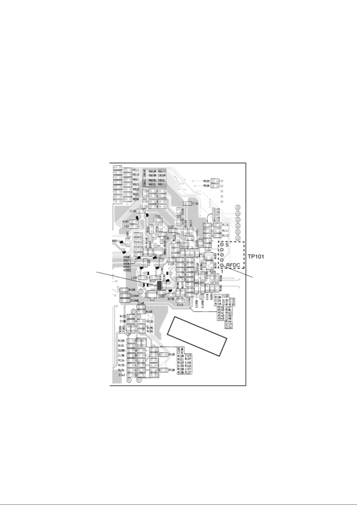
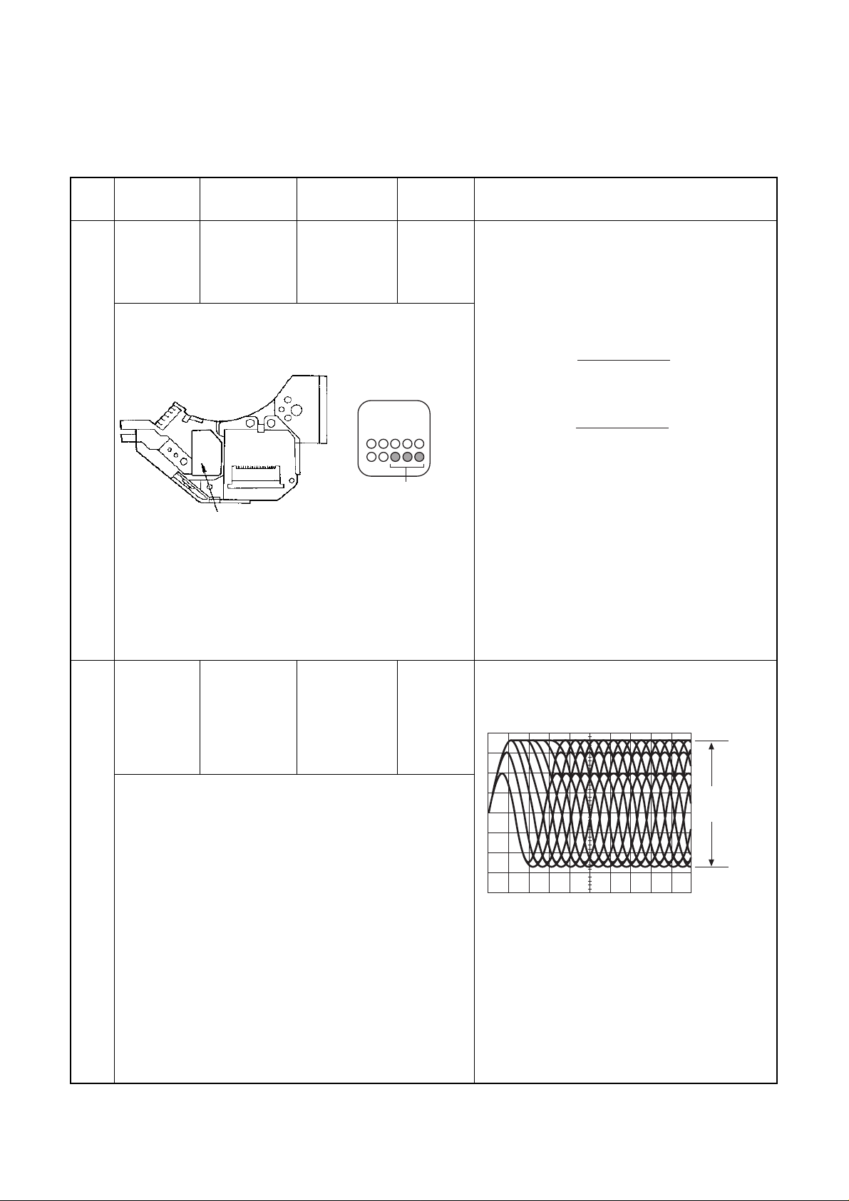
2.2. Parts Location for Electrical Check
● CD P.C.B. Ass'y of the CD Player
(Dip Side View)
SS-9 Main Unit Section
R101
Laser Current Check
Pin 1 of TP101
EFM Signal
Fig. 1.1 Parts Location for Electrical Check -- CD Player
1-8
2.3. Electrical checks for CD Player
Note: Do the same check for CD Player Nos. 1 to 3.
SS-9 Main Unit Section
STEP ITEM SIGNAL OUTPUT ADJUST- REMARKS
SOURCE CONNECTION MENT
1 Laser Current ABEX Test Disc DC Voltmeter —
Check TCD-784 across R101
on CD P.C.B.
1. Turn ON the power and load a test disc.
(To load the test disc, press the Open/Close button
of the CD Player.)
2. Play back the test disc and calculate the current
flowing into R101 on the CD P.C.B. Ass'y from the
following formula.
Voltmeter Value
I(Measured) =
R101 (10 Ohms)
Example:
KSS-540A
I(Measured) =
510.3 (mV)
10 (ohms)
3. Check that the I(Measured) obtained in 2 and the
IOP(oo.omA)
Laser Pickup
KSS-540A
rated current value (IOP) shown on the label are
almost the same.
[How to read IOP on the label]
The shaded "OOO" on the label shows the IOP.
If "OOO" is 475, the IOP is 47.5mA.
NOTE: The calculated current (I(Measured))
should be in a range of 30 to 60 mA. If the
value is large, the pickup will be defective.
4. Stop the test disc.
= oo.o mA
= 51.03 mA
2 EFM Signal ABEX Test Disc Oscilloscope —
Adjustment TCD-784 between
pin 1 of TP101
and GND
on CD P.C.B.
1. Play back the first track of the test disc.
2. Be sure that the peak-to-peak value of the EFM
waveform is approx. 1V.
Approx. 1Vp-p
Oscilloscope Setting:
AC Mode, 0.2 V/div, 0.5 µs/div
3. Stop the test disc and eject it.
1-9

STEP ITEM SIGNAL OUTPUT ADJUST- REMARKS
SOURCE CONNECTION MENT
SS-9 Main Unit Section
3 Operation ABEX Test Disc —
Check TCD-726
or TCD-725A
Make sure that no noise nor track-jumping is found in
the following programs on the test disc.
To select the desired program, press Track Search
button on the Main Unit or Remote Control
• Interruption 0.8mm: 4th program
• Black dot Ø0.6mm: 8th program
• Simulated fingerprint Ø65µm: 13th program
1-10
3. MECHANISM ASS'Y AND PARTS LIST
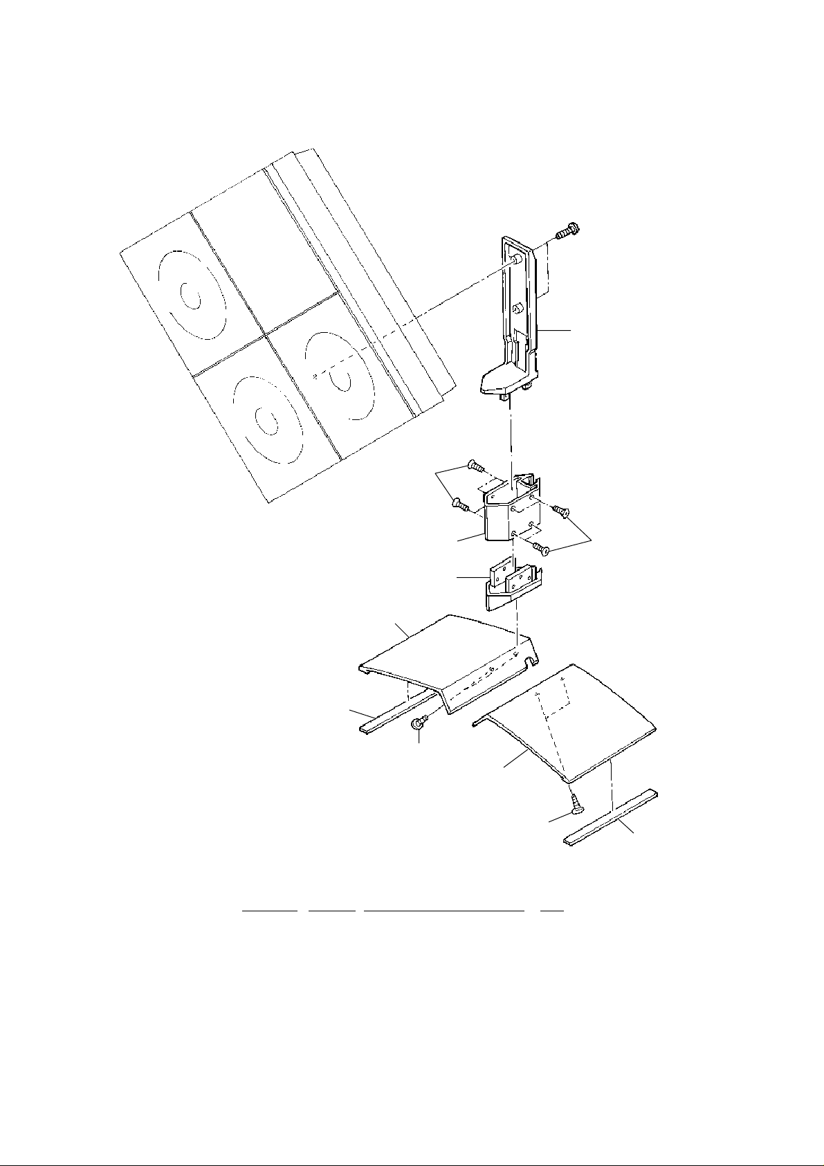
3.1. Main Stand Ass'y
SS-9 Main Unit Section
06
L01
05
04
03
01
L02
02
Fig. 3.1
L02
3.1. Main Stand Ass'y
Schematic
Ref. No. Part No. Description Q'ty
— Main Stand Ass’y (Main Unit) 1
01 0J08792A Base Cushion Center S 2
02 0H08793B Stand Base Center R 1
03 0H08792B Stand Base Center L 1
04 0H08791D Base Joint 1
05 0H08796B Stand Pole 1
06 0H08790C Stand Holder Center 1
L01 0E04323A BT4x10 + Oval Countersunk
L02 0E03972A BT4x12 + Binding
L01
01
1-11
SS-9 Main Unit Section
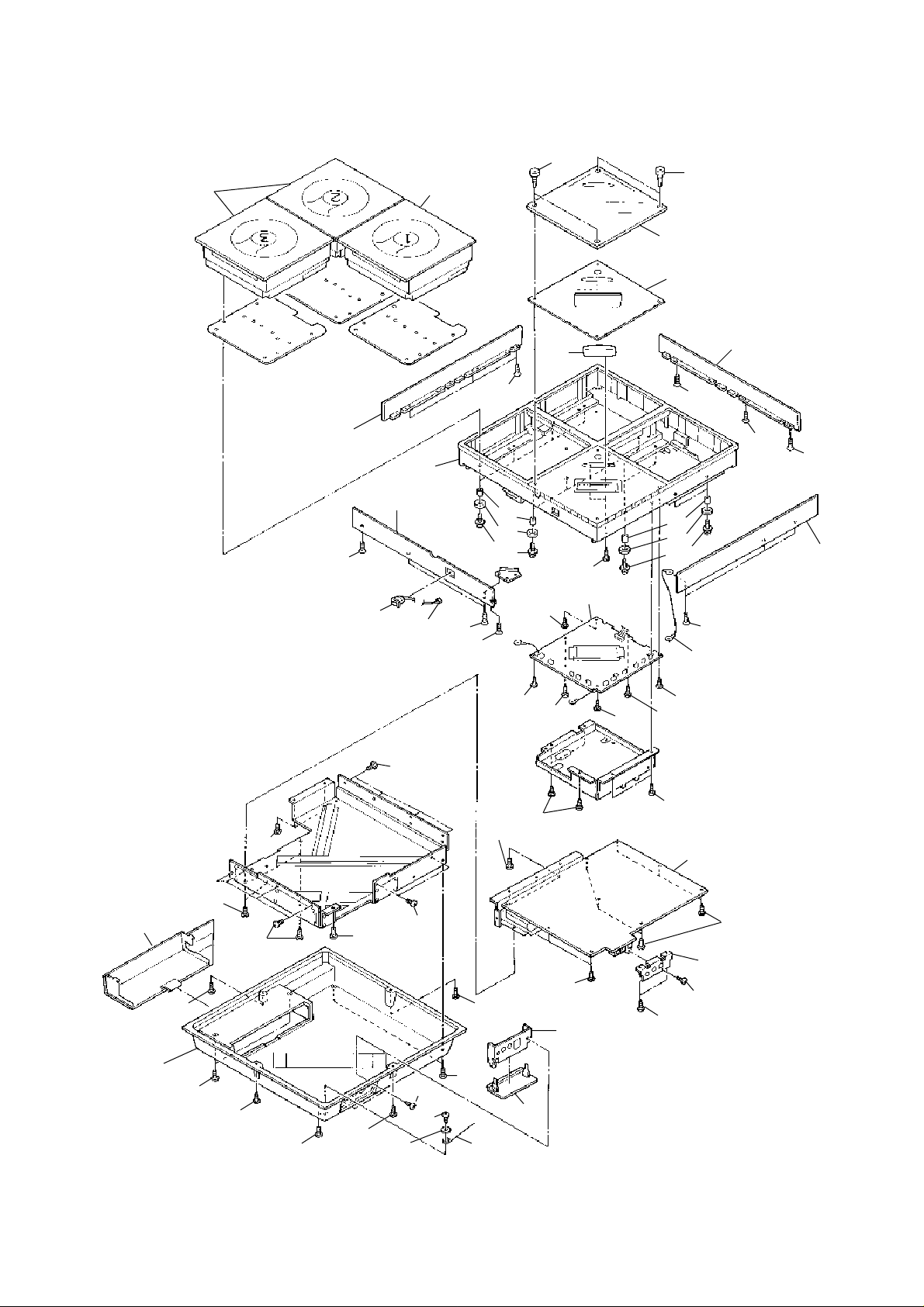
3.2. Synthesis (Main Unit)
Mechanism CD
Ass'y 1 (A01) 01
L03
06
09
11
Mechanism CD
Ass'y 2 (A01)
02
L02
08
L04
03
L02
L03
12
13
L05
L01
07
L15
14
04
05
12
13
L04
L01
06
L03
L02
L03
06
L02
21
15
16
L08
L09
L16
L08
L07
L07
L09
L07
L08
L07
L11
L07
L13
L10
L08
L09
19
Fig. 3.2
L14
L05
L06
18
L06
L12
17
L06
L05
L06
L06
20
L12
10
L17
L18
1-12
Loading...