

NAIS RK1-12V, RK1-24V, RK1-3V, RK1-4.5V, RK1-5V Datasheet
...
1Ex. RK L2
Contact arrangement
1: Standard type
1R: R type
(See Schematic on next page.)
Note: Standard packing; Carton: 50 pcs. Case 500 pcs.
Nil: Single side stable
L: 1 coil latching
L2: 2 coil latching
3, 4.5, 5, 6, 9, 12,
24 V
Operating function Coil voltage, DC
24V
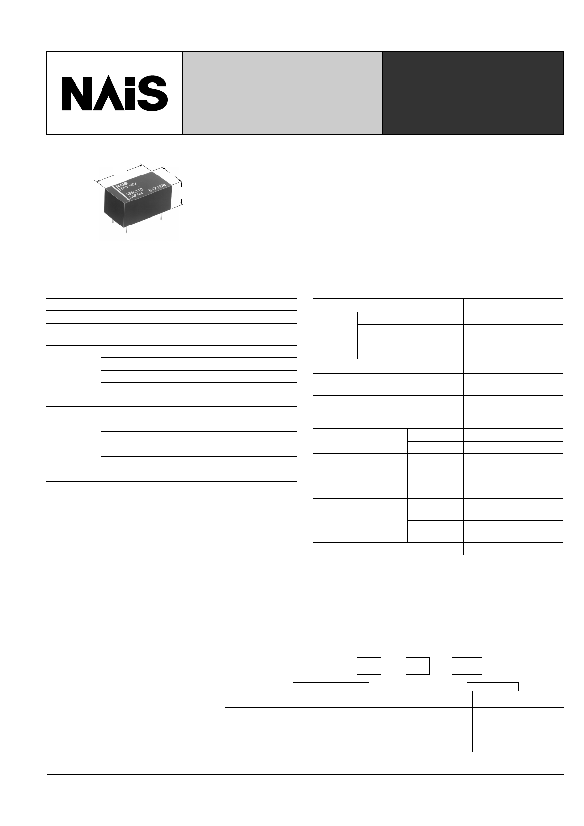
1.5 GHz MICROW AVE RELAY
20.2
.795
11.2
.441
9.7
.382
mm inch
SPECIFICATIONS
Contact
Arrangement
Contact material
Initial contact resistance, max.
(By HP4328A)
Max. switching power
Max. switching voltage
Rating
High frequency
characteristics
(
Impedance 50Ω
Expected
life (min.
operations)
Max. switching current
Nominal switching
capacity
Isolation
Insertion loss
)
V.S.W.R.
Mechanical
Electrical
0.01 A 24 V DC
10 W 1.2 GHz
0.01 A 24 V DC 10 W (at
1.2 GHz, Impedance 50Ω)
Coil (at 25°C, 68°F)
Single side stable 200 mW
1 coil latching
2 coil latching
1 Form C
Gold-clad
100 mΩ
10 W
30 V DC
0.5 A
Min. 60 dB (at 1.5 GHz)
Max. 0.3 dB (at 900 MHz)
Max. 1.5 (at 900 MHz)
5×10
3×10
Nominal operating power
200 mW
400 mW
10
RK-RELAYS
• Excellent high frequency characteristics
Isolation: Min. 60dB (at 1.5 GHz)
Insertion loss: Max. 0.3dB (at 900 MHz)
• V.S.W.R.: Max. 1.5 (at 900MHz)
• High sensitivity in small size
Size: 20.2 × 11.2 × 9.7 mm .795 × .441 × .382 inch
Nominal power consumption: 200 mW (single side stable type)
• Sealed construction for automatic cleaning
• Latching types are also available
Characteristics
Initial insulation resistance*
Initial
breakdown
voltage*
Operate time [Set time]*3 (at nominal voltage)
Release time (without diode) [Reset time]*
(at nominal voltage) *2
Temperature rise
6
5
5
Shock resistance
Vibration
resistance
Conditions for operation,
transport and storage
(Not freezing and condensing
at low temperature)
Unit weight
Remarks
* Specifications will vary with foreign standards certification ratings.
1
Measurement at same location as “Initial breakdown voltage” section
*
2
Detection current: 10mA
*
3
Excluding contact bounce time
*
4
Half-wave pulse of sine wave: 11ms, detection time: 10µs
*
5
Half-wave pulse of sine wave: 6ms
*
6
Detection time: 10µs
*
Between open contacts
Between contact and coil
2
Between contact and
earth terminal
1
Functional*
Destructive*
Functional*
Destructive
Ambient temp.
Humidity
4
6
Min. 100 MΩ at 500 V DC
500 Vrms
1,000 Vrms
500 Vrms
Approx. 6 ms [Approx. 5ms]
3
Approx. 3 ms [Approx. 5ms]
Max. 60°Cwith nominal coil
voltage across coil and at
nominal switching capacity
2
Min. 196 m/s
5
Min. 980 m/s2 {100 G}
at double amplitude of 3 mm
at double amplitude of 5 mm
10 to 55 Hz
10 to 55 Hz
–40°C to 60°C
–40°F to 140°F
5 to 85% R.H.
Approx. 4.4 g .155 oz
{20 G}
TYPICAL
APPLICATIONS
• Audio visual equipment
broadcast satellite tuners
VCRs, CATVs, TVs
• Communication equipment
automobile telephones
maritime telephones
• Instrumentation
test equipment
measuring equipment
ORDERING INFORMATION
101
RK
TYPES ANE COIL DATA (at 20°C 68°F)
• Single side stable type
Part No.
voltage,
V DC
Nominal
RK1-3V 3 2.25 0.3 45 66.7
RK1R-3V
RK1-4.5V 4.5 3.38 0.45 101 44.4 4.95RK1R-4.5V
RK1-5V
RK1-6V
RK1-9V
RK1-12V
RK1R-5V
RK1R-6V
RK1R-9V
RK1R-12V
RK1R-24V
12 9 1.2 720 16.7 200 13.2
24 18 2.4 2,880 8.3 200 26.4RK1-24V
Pick-up
voltage, max.
V DC
Drop-out
voltage, min.
V DC
Coil
resistance,
Ω (±10%)
Nominal
operating
current, mA
Nominal
operating
power, mW
200
200
5 3.75 0.5 125 40.7 200 5.5
6 4.5 0.6 180 33.3 200 6.6
9 6.75 0.9 405 22.2 200 9.9
• 1 coil latching type
Nominal
Part No.
voltage,
V DC
RK1-L-3V 3 2.25 2.25 45 66.7
RK1R-L-3V
RK1-L-4.5V 4.5 3.38 3.38 101 44.4
RK1-L-5V
RK1-L-6V
RK1-L-9V
RK1-L-12V
RK1R-L-5V
RK1R-L-6V
RK1R-L-9V
RK1R-L-12V
RK1R-L-24V
12 9 9 720 16.7 200 13.2
24 18 18
Set
voltage, max.
V DC
Reset
voltage, max.
V DC
Coil
resistance,
Ω (±10%)
Nominal
operating
current, mA
Nominal
operating
power, mW
200
200
5 3.75 3.75 125 40 200 5.5
6 4.5 4.5 180 33.3 200 6.6
9 6.75 6.75 405 22.2 200 9.9
2,880 8.3 200 26.4RK1-L-24V
• 2 coil latching type
Part No.
voltage,
V DC
Nominal
RK1-L2-3V 3 2.25 22.5 133.3 400 3.3
RK1-L2-5V
RK1-L2-6V
RK1-L2-9V
RK1-L2-12V
RK1R-L2-3V
RK1R-L2-5V
RK1R-L2-6V
RK1R-L2-9V
RK1R-L2-12V
RK1R-L2-24V
12 9 360 33.3
24 18 1,440 16.7 400 26.4RK1-L2-24V
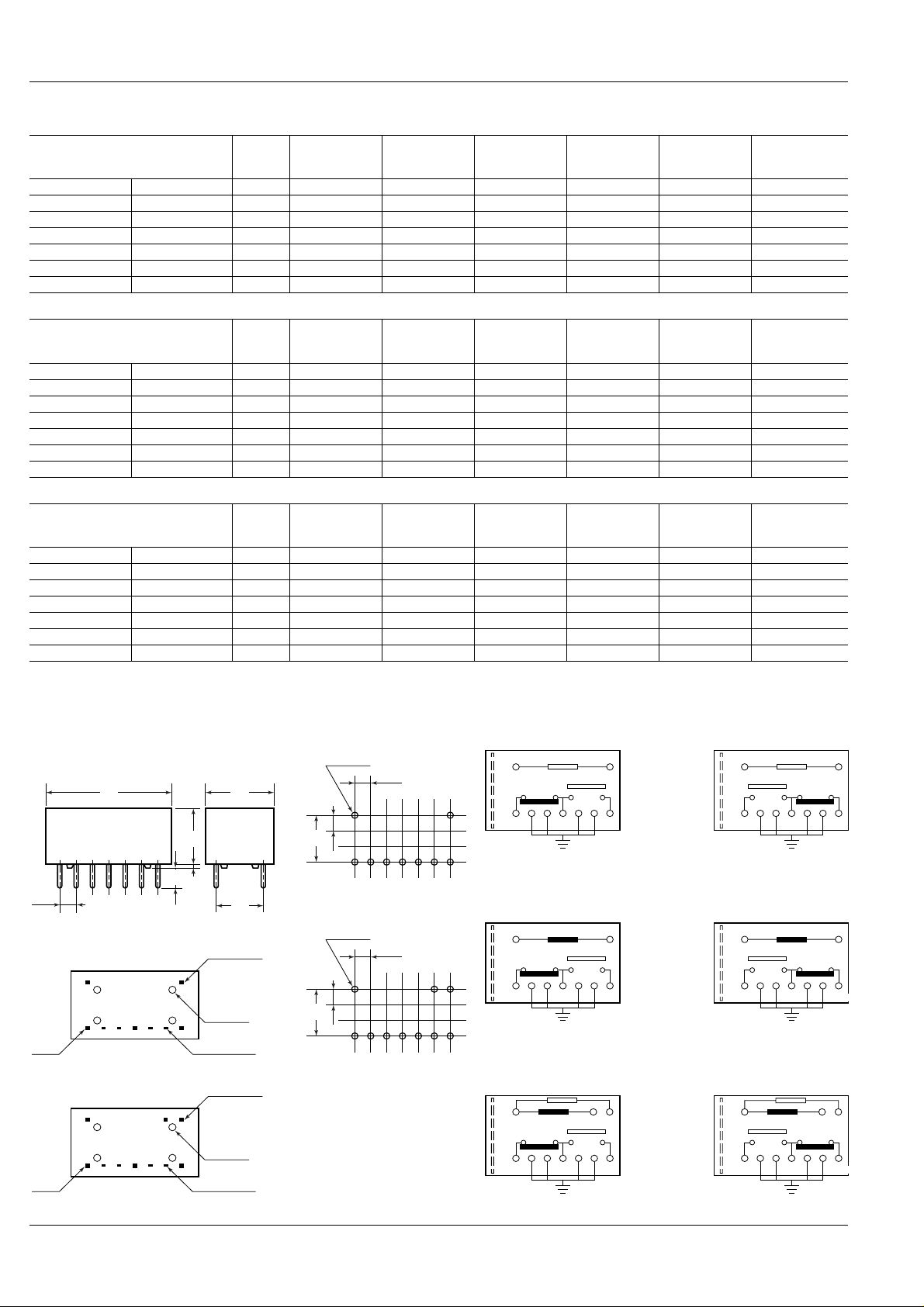
DIMENSIONS
Set
voltage, max.
V DC
5 3.75 62.5 80
6 4.5 90 66.7
9 6.75 202.5 44.4
PC board pattern (Copper-side view) Schematic (Bottom view)
Reset
voltage, max.
V DC
2.25
3.38RK1-L2-4.5V 4.5 3.38 50.6 88.9 400 4.95RK1R-L2-4.5V
3.75
4.5
6.75
9
18
Coil
resistance,
Ω (±10%)
Nominal
operating
current, mA
Nominal
operating
power, mW
400
400
400
400
Maximum.
allowable
voltage, V DC
(at 60°C 140°F)
Maximum.
allowable
voltage, V DC
(at 60°C 140°F)
Maximum.
allowable
voltage, V DC
(at 60°C 140°F)
3.3
3.3
4.95RK1R-L-4.5V
5.5
6.6
9.9
13.2
mm inch
20.2
.795
2.54
.100
(Single side stable and
1 coil latching)
3-0.45
3-.018
(2 coil latching)
3-0.45
3-.018
3.5
.138
9.1
.358
0.6
.024
4-0.6×0.25
4-.024×.010
4-0.6×0.25
4-.024×.010
11.2
.441
7.62
.300
2-0.6×0.3
2-.024×.012
Stand-off
3-0.6×0.3
3-.024×.012
Stand-off
(Single side stable and
1 coil latching)
9-0.9 dia.
9-.035 dia.
2.54
.100
7.62
.300
2.54
.100
(2 coil latching)
10-0.9 dia.
10-.035 dia.
2.54
.100
7.62
.300
2.54
.100
Tolerance: ±0.1 ±.003
Standard contact arrangement
RK1
–
1
+
Single side
7
stable
(Deenergized
14
13 12 11 10 9 8
N.C. COM N.O.
condition)
RK1-L
+
1
–
7
1 coil
latching
(Reset
14
13 12 11 10 9 8
RESET COM SET
condition)
RK1-L2
2 coil
17
14
13 12 11 10 9 8
RESET COM SET
6
latching
+–+
(Reset
condition)
R type contact arrangement
RK1R
–
1
14
13 12 11 10 9 8
N.O. COM N.C.
+
RK1R-L
+
1
14
13 12 11 10 9 8
SET COM RESET
–
RK1R-L2
17
14
13 12 11 10 9 8
SET COM RESET
6
+–+
7
7
102
General tolerance: ±0.3 ±.012
 Loading...