

NAIS HG4-DC6V, HG4-DC48V, HG4-DC24V, HG4-DC200V, HG4-DC12V Datasheet
...
422
HG-RELAYS
20 AMP POWER RELAY
36
1.417
56
2.205
a
mm inch
a
HG2 34.0 1.339
HG3 50.0 1.969
HG4 68.0 2.667
FEATURES
•
Large capacity — 20 A 250 V A C resistive and 1.5 kW 3 phase
220 V AC motor loads
• High contact reliability after long use
• Usable with direct soldering,
quick-connect and plug-in terminals. (.250)
SPECIFICATIONS
Contacts
Expected life (min. operations)
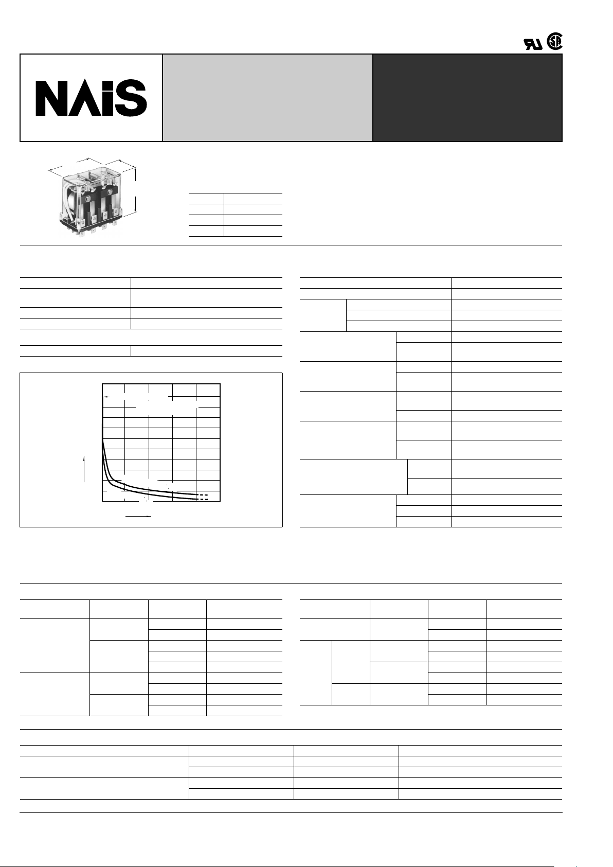
Life curve for AC types
Characteristics (at 60 Hz, 20 ° C 68 ° F)
Arrangement 2 Form C, 3 Form C, 4 Form C
Initial contact resistance, max.
(By voltage drop 6 V DC 1A)
15 m
Ω
Contact material Silver alloy
Nominal switching capacity 20 A 250 V AC (resistive)
Mechanical (at 180 cpm) AC type: 10
7
, DC type: 10
6
5101520
0
100
200
300
400
500
600
700
800
900
1,000
Load current, A
Operations, ×10
4
125 V AC cosϕ = 1
2
5
0
V
A
C
c
o
s
ϕ
=
1
Mechanical life : 10
7
Operating frequency:
180 op./min.
Maximum operating speed 20 cpm
Initial insulation resistance*
1
Min. 100 M Ω at 500 V DC
Initial
breakdown
voltage*
2
Between open contacts 2,000 Vrms for 1 min.
Between contacts sets 2,000 Vrms for 1 min.
Between contacts and coil 2,000 Vrms for 1 min.
Operate time*
3
(approx.)
(at nominal voltage)
2 Form C type 15 ms
3 Form C &
4 Form C type
25 ms
Release time
(without diode)*
3
(approx.)
(at nominal voltage)
2 Form C type 15 ms
3 Form C &
4 Form C type
25 ms
Shock resistance
Functional*
4
98 m/s
2
{10 G} (except for the
contact moving direction)
Destructive*
5
980 m/s
2
{100 G}
Vibration resistance
Functional*
6
58.8 m/s
2
{6 G}, 10 to 55 Hz
at 1 mm double amplitude
Destructive
117.6 m/s
2
{12 G}, 10 to 55 Hz
at 2 mm double amplitude
Conditions for operation,
transport and storage*
7
(Not freezing and condensing
at low temperature)
Ambient
temp.
–50
°
C to +40 ° C
–58
°
F to +104 ° F
Humidity 5 to 85% R.H.
Unit weight
2 Form C type Approx. 130 g 4.59 oz
3 Form C type Approx. 185 g 6.53 oz
4 Form C type Approx. 240 g 8.47 oz
Remarks
* Specifications will vary with foreign standards certification ratings.
*
1
Measurement at same location as "Initial breakdown voltage" section
*
2
Detection current: 10 mA
*
3
Excluding contact bounce time
*
4
Half-wave pulse of sine wave: 11ms; detection time: 10 µ s
*
5
Half-wave pulse of sine wave: 6ms
*
6
Detection time: 10 µ s
*
7
Refer to 5. Conditions for operation, transport and storage mentioned in
AMBIENT ENVIRONMENT (Page 61).
Electrical life with AC load
Note: In case of an electromagnet or exiting coil load (solenoid, etc.), the value of the motor or lamp load is applicable.
AC load Voltage, V AC Current, A
Expected life
(min. operations)
Resistive
(cos
ϕ
]
1)
125
20 5
×
10
5
15 7.5 × 10
5
250
20 2
×
10
5
15 5 × 10
5
10 7.5 × 10
5
Inductive
(cos
ϕ
]
0.4)
125
15 2
×
10
5
10 5 × 10
5
250
10 2
×
10
5
7.5 5 × 10
5
AC load Voltage, V AC Capacity, kW
Expected life
(min. operations)
Lamp 125
0.5 2
×
10
5
0.3 5 × 10
5
Motor
Single
phase
125
0.75 2
×
10
5
0.4 5 × 10
5
250
0.75 2
×
10
5
0.4 5 × 10
5
Three
phase
250
1.5 2
×
10
5
0.75 5 × 10
5
Electrical life with DC load
Note: For DC inductive load, use of an arc extinguishing circuit is recommended.
DC load Voltage, V DC Current, A Expected life (min. operations)
Resistive
24 15 5
×
10
5
125 0.8 5 × 10
5
Inductive (L/R
]
7 ms)
24 10 5
×
10
5
125 0.4 5 × 10
5
HG
423
TYPICAL
APPLICATIONS
Industrial machinery, machine tools, food
processing and packing machines, office
machines, transportation equipment and
amusement devices.
ORDERING INFORMATION
Ex. HG 2 AC 240 V
Contact arrangement
(Note) Standard packing Carton: HG2 20 pcs.
HG3, HG4 10 pcs.
UL/CSA approved type is standard.
2: 2 Form C
3: 3 Form C
4: 4 Form C
Coil voltage
AC 6, 12, 24, 48, 115, 220, 240 V
DC 6, 12, 24, 48, 110, 200 V
Case: HG2 100 pcs.
HG3, HG4 50 pcs.
TYPES AND COIL DATA
DC TYPES at 20 ° C 68 ° F
AC TYPES (50/60 Hz) at 60 HZ, 20 ° C 68 ° F
Type Part No.
Nominal coil
voltage, V DC
Pick-up
voltage,
V DC (max.)
Drop-out
voltage,
V DC (min.)
Max.
allowable,
V DC voltage
Coil
resistance,
Ω ( ±
10%)
Nominal coil
current,
mA
Operating
power, W
HG2
(2 Form C)
HG2-DC6V 6 4.8 0.9 6.6 26.4 230 (approx.) 1.4
HG2-DC12V 12 9.6 1.8 13.2 100 119.6 (approx.) 1.4
HG2-DC24V 24 19.2 3.6 26.4 416 57.6 (approx.) 1.4
HG2-DC48V 48 38.4 7.2 52.8 1585 30.3 (approx.) 1.4
HG2-DC110V 110 88 16.5 121 7650 14.4 (approx.) 1.4
HG2-DC200V 200 160 20 220 27,800 7.2 (approx.) 1.4
HG3
(3 Form C)
HG3-DC6V 6 4.8 0.9 6.6 22.7 264 (approx.) 1.6
HG3-DC12V 12 9.6 1.8 13.2 89.5 134 (approx.) 1.6
HG3-DC24V 24 19.2 3.6 26.4 364 66 (approx.) 1.6
HG3-DC48V 48 38.4 7.2 52.8 1450 33.1 (approx.) 1.6
HG3-DC110V 110 88 16.5 121 6670 16.5 (approx.) 1.6
HG3-DC200V 200 160 20 220 23,800 8.4 (approx.) 1.6
HG4
(4 Form C)
HG4-DC6V 6 4.8 0.9 6.6 18.5 325 (approx.) 2.1
HG4-DC12V 12 9.6 1.8 13.2 71.4 168 (approx.) 2.1
HG4-DC24V 24 19.2 3.6 26.4 296 81.2 (approx.) 2.1
HG4-DC48V 48 38.4 7.2 52.8 1050 45.7 (approx.) 2.1
HG4-DC110V 110 88 16.5 121 5420 20.3 (approx.) 2.1
HG4-DC200V 200 160 20 220 15,500 12.9 (approx.) 2.1
Type Part No.
Nominal coil
voltage,
V AC
Pick-up
voltage,
V AC (max.)
Drop-out
voltage,
V AC (min.)
Max.
allowable,
V AC voltage
Inductance,
H
Nominal coil
current,
mA
Operating
power,
VA
HG2
(2 Form C)
HG2-AC6V 6 4.8 1.8 6.6 0.026 600 (approx.) 3.6
HG2-AC12V 12 9.6 3.6 13.2 0.104 300 (approx.) 3.6
HG2-AC24V 24 19.2 7.2 26.4 0.416 150 (approx.) 3.6
HG2-AC48V 48 38.4 14.4 52.8 1.660 75 (approx.) 3.6
HG2-AC115V 115 92 34.5 126.5 9.531 31.3 (approx.) 3.6
HG2-AC220V 220 176 66 242 34.96 16.4 (approx.) 3.6
HG2-AC240V 240 192 72 264 41.68 15 (approx.) 3.6
HG3
(3 Form C)
HG3-AC6V 6 4.8 1.8 6.6 0.018 864 (approx.) 5.2
HG3-AC12V 12 9.6 3.6 13.2 0.073 432 (approx.) 5.2
HG3-AC24V 24 19.2 7.2 26.4 0.290 216 (approx.) 5.2
HG3-AC48V 48 38.4 14.4 52.8 1.163 108 (approx.) 5.2
HG3-AC115V 115 92 34.5 126.5 6.648 45.2 (approx.) 5.2
HG3-AC220V 220 176 66 242 24.26 23.6 (approx.) 5.2
HG3-AC240V 240 192 72 264 29.06 21.6 (approx.) 5.2
HG4
(4 Form C)
HG4-AC6V 6 4.8 1.8 6.6 0.012 1264 (approx.) 7.6
HG4-AC12V 12 9.6 3.6 13.2 0.050 632 (approx.) 7.6
HG4-AC24V 24 19.2 7.2 26.4 0.199 316 (approx.) 7.6
HG4-AC48V 48 38.4 14.4 52.8 0.795 158 (approx.) 7.6
HG4-AC115V 115 92 34.5 126.5 4.557 66.1 (approx.) 7.6
HG4-AC220V 220 176 66 242 16.89 34 (approx.) 7.6
HG4-AC240V 240 192 72 264 19.87 31.6 (approx.) 7.6
Notes:
1. The coil current ranges is ± 15% for AC (60 Hz), ± 10% for DC (20 ° C 68 ° F).
2. These relays are applicable to a r ange of 80% to 110% of the nominal coil voltage.
However , it is recommended that the rela y be used in a range of 85% to 110% of the
nominal coil voltage, taking the temporary voltage variation into consideration. For
AC types, when operating voltage is 70% of nominal coil voltage, "buzzing" will oc-
cur, and a large amount of current will flow, burning the coil.
3. Each coil resistance of DC types is the measured value at coil temperature of
20 ° C 68 ° F. Please compensate the coil resistance by ± 0.4%, each time the coil temperature changes by ± 1 ° C.
 Loading...