

NAIS ADQ13Q012, ADQ13Q009, ADQ13Q006, ADQ23Q04H, ADQ23Q024 Datasheet
...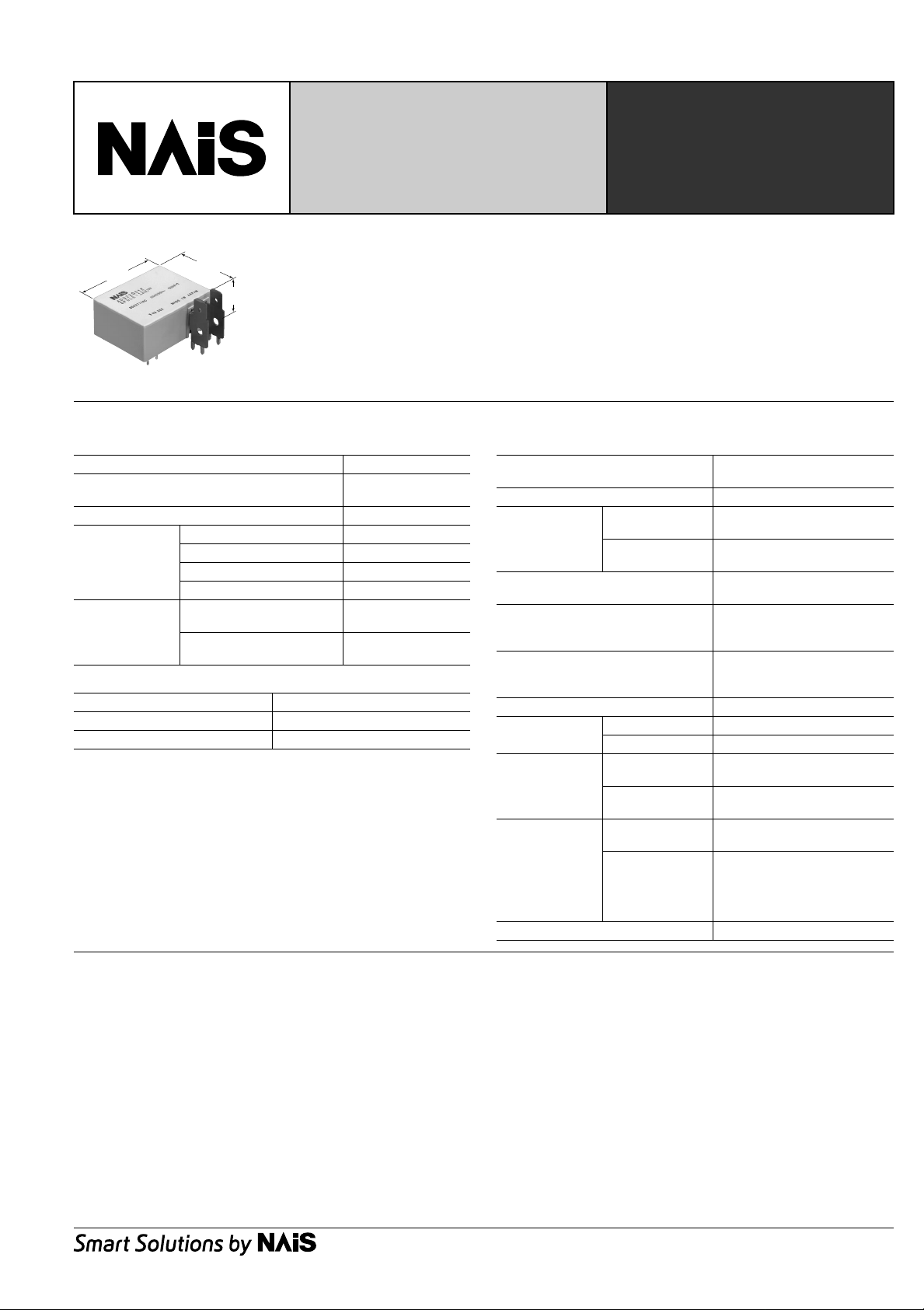
30A PO WER LATCHING
RELAY
FEATURES
38.0
1.496
29.0
1.142
17.3
.681
1. Compact with high capacity
Although compact this relay can handle
high capacity control of 30A.
2. Latching type
With latching this relay contributes to energy conservation in devices.
SPECIFICATIONS
Contact
Arrangement 1 Form A
Initial contact resistance, max.
(By voltage drop 6 V DC 1 A)
Contact material Silver alloy
Nominal switching capacity 30 A 250V AC
Rating
(resistive load)
Max. switching power 7,500 V A
Max. switching voltage 250V AC
Max. switching current 30 A
Mechanical
Expected life
(min. operations)
(at 180 cpm)
Electrical
(Resistive load)
Coil
Nominal operating power
1 coil latching 800 mW
2 coil latching 1,600 mW
Remarks
* Specifications will vary with foreign standards certification ratings.
*1At nominal switching capacity, operating frequency: 3s ON, 3s OFF
*2Measurement at same location as "Initial breakdown voltage" section.
3
Detection current: 10mA
*
*4Wave is standard shock voltage of ±1.2 × 50µs according to JEC-212-1981
5
Excluding contact bounce time.
*
*6By resistive method, max. switching current
7
Half-wave pulse of sine wave: 11 ms; detection time: 10 µs
*
*8Half-wave pulse of sine wave: 6 ms
9
Detection time: 10 µs
*
*10Refer to 5. Usage, transport and storage conditions mentioned in NOTES
*11Under the packing condition, allowable temperature range is from –40 to +65°C
–40° to +149°F.
30 m
10
104*
Ω
6
1
DQ-RELAYS
3. High insulation
Designed with an insulation distance of at
least 8 mm.
4. Cadmium and lead free
5. Complies with safety standards
UL, CSA and VDE approved.
Characteristics
Max. operating speed
(at rated load)
Initial insulation resistance*
2
Min. 1,000 MΩ (at 500 V DC)
Between open
Initial breakdown
3
voltage*
contacts
Between contacts
and coil
Surge voltage between contact and
4
coil*
Operate time [Set time]*
5
(at 20°C)
(at nominal voltage)
Release time [Reset time]*
5
(at 20°C)
(at nominal voltage)
Temperature rise (at 65°C)*
Shock
resistance
Vibration
resistance
Conditions for
operation,
transport and
10
storage*
(Not freezing and
condensing at
6
Functional*
Destructive*
Functional*
Destructive
Ambient
temperature*
7
8
9
at double amplitude of 1.5mm
at double amplitude of 2.0mm
11
Humidity 5 to 75% R.H.
low temperature)
Unit weight Approx. 35 g 1.23 oz
180 cpm
1,500 Vrms for 1 min.
4,000 Vrms for 1 min.
Min. 10,000 V (initial)
Max. 20ms
Max. 20ms
Max. 50°C
Min. 200 m/s2{20 G}
Min. 1,000 m/s2{100 G}
10 to 55Hz
10 to 55Hz
–40°C to +65°C
–40°F to +149°F
DQ
TYPICAL APPLICATIONS
• Time switches
• Electric water heaters
• Remote control of electric power meters
1
DQ
ORDERING INFORMATION
ADQ
Operating function Contact capacity
1: 1 coil latching
3: 30 A
3Q0
Terminal shape
Q: 250 Faston terminal
2: 2 coil latching
TYPES AND COIL DATA (at 20°C 68°F)
• 1 coil latching type
Contact
arrangement
1 Form A
Part No.
voltage,
V DC
ADQ13Q04H 4.5 3.15 3.15 25.3 177.8 800 5.85
ADQ13Q006 6 4.2 4.2 45 133.3 800 7.8
ADQ13Q009 9 6.3 6.3 101 88.9 800 11.7
ADQ13Q012 12 8.4 8.4 180 66.7 800 15.6
ADQ13Q024 24 16.8 16.8 720 33.3 800 31.2
Nominal
Set voltage,
max. V DC
(initial)
Reset voltage,
max. V DC
• 2 coil latching type
Contact
arrangement
1 Form A
Set
Part No.
Nominal
voltage,
V DC
voltage,
max.
V DC
(initial)
ADQ23Q04H 4.5 3.15 3.15 12.7 12.7 355.6 355.6 1,600 1,600 5.85
ADQ23Q006 6 4.2 4.2 22.5 22.5 266.7 266.7 1,600 1,600 7.8
ADQ23Q009 9 6.3 6.3 50.6 50.6 177.8 177.8 1,600 1,600 11.7
ADQ23Q012 12 8.4 8.4 90 90 133.3 133.3 1,600 1,600 15.6
ADQ23Q024 24 16.8 16.8 360 360 66.7 66.7 1,600 1,600 31.2
Reset
voltage,
max.
V DC
(initial)
Coil resistance, Ω
Set coil
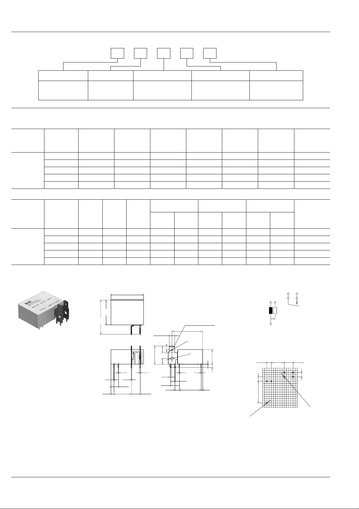
DIMENSIONS
(initial)
(±10%)
Contact characteristics
0: Standard contact
Coil
resistance, Ω
(±10%)
Nominal operating
current, mA (±10%)
Reset
coil
Set coil
Nominal
operating
current, mA
(±10%)
Reset
coil
Coil voltage (DC)
4H: 4.5 V
06: 6 V
12: 12 V
24: 24 V
09: 9 V
Nominal
operating
power, mW
Max. allow able
voltage,
V DC
Nominal operating
power, mW Max. allow able
voltage,
V DC
Set coil
Reset
coil
mm inch
40.1
1.579
29.0
1.142
.031
3.6
.142
Schematic (Bottom view)
38.0
1.496
250 faston terminal
35.8
5.08
.200
1.409
1.7 dia.
.067 dia.
3.3 dia.
.130 dia.
0.4
.016
1.5
.059
25.4
1.000
0.4
.016
.012
1.8
.071
Note) Terminal No.3 is only for 2 coil latching
type.
17.3
0.3
.681
3.7
.146
PC board pattern (Bottom view)
5.08
.200
25.4
1.000
6.35
.250
4.5
.177
7.9
.311
21.4
.843
6.9
272
0.8
.031
0.8
0.8
.031
5.08
.200
20.32
.800
0.8
.031
10.16
.400
1.5
.059
5.08
.200
Reset
coil
5.08
.200
–
3–2
Set
coil
1
+
15.24
.600
General tolerance: ±0.3 ±.012
3-1.5 dia.
3-.059 dia.
6
5
7
4
10.16
.400
5.08
.200
4-2.0 dia.
4-.079 dia.
Tolerance: ±0.1 ±.004
2
 Loading...