


OWNERS MANUAL
PREAMPLIFIERS
INTEGRATED AMPLIFIERS,POWER AMPLIFIERS
ENGLISH DEUTSCH FRANÇAIS ITALIANO

SAFETY INSTRUCTIONS
In order to comply with current European safety regulations
it is essential that the Naim loudspeaker connectors
supplied with amplifiers and loudspeakers are used.
Do not under any circumstances allow anyone to modify
your Naim equipment without first checking with the factory,
your retailer, or your distributor. Unauthorised modifications
will invalidate your guarantee.
Equipment must not be exposed to dripping or splashing
and no objects filled with liquid, such as vases, should be
placed on the equipment.
For your own safety do not under any circumstances open
Naim equipment without first disconnecting it from the
mains.
Warning: an apparatus with CLASS I construction shall
be connected to a mains socket outlet with a protective
earthing connection.
Where the mains plug or an appliance coupler is used as
the disconnect device, the disconnect device shall remain
readily operable. To disconnect the equipment from the
mains remove the mains plug from the mains outlet.
The following label is attached to all mains powered
equipment:
WARNING
THIS APPARATUS
MUST BE EARTHED
NOTE
This equipment has been tested and found to comply
with the relevant EMC and Safety Standards, and, where
applicable, also complies with the limits for a class B digital
device, pursuant to Part 15 of the FCC Rules.
These limits are designed to provide reasonable protection
against harmful interference in a residential installation.
This equipment generates, uses and can radiate radio
frequency and, if not installed and used in accordance
with the instructions, may cause harmful interference to
radio communications. However, there is no guarantee
that interference will not occur in a particular installation. If
this equipment does cause harmful interference to radio or
television reception, which can be determined by turning
off and on, the user is encouraged to try to correct the
interference by one or more of the following measures:
• Reorient or relocate the receiving antenna.
• Increase the separation between the equipment and the
receiver.
• Connect the equipment into an outlet on a circuit different
from that to which the receiver is connected.
• Consult your Naim retailer or an experienced radio/TV
technician for help.
Contents
Page Section
E1 1 Connections
E1 2 Mains Power
E2 3 General Installation
E3 4 NAC 552 Introduction and Installation
E4 5 NAC 552 Controls and Connections
E5 6 NAC 552 Specification
E6 7 NAC 252 Introduction and Installation
E6 8 NAC 252 Controls and Connections
E7 9 NAC 252 Specification
E8 10 NAC 282 Introduction and Installation
E8 11 NAC 282 Controls and Connections
E10 12 NAC 282 Specification
E11 13 NAC 202 Introduction and Installation
E11 14 NAC 202 Controls and Connections
E12 15 NAC 202 Specification
E13 16 NAC 152 XS Introduction and Installation
E14 17 NAC 152 XS Controls and Connections
E16 18 NAC 152 XS Specification
E17 19 Supernait Introduction and Installation
E19 20 Supernait Controls and Connections
E21 21 Supernait Specification
E22 22 Nait XS Introduction and Installation
E23 23 Nait XS Controls and Connections
E25 24 Nait XS Specification
E26 25 Nait 5i Introduction and Installation
E26 26 Nait 5i Controls and Connections
E27 27 Nait 5i Specification
E28 28 Preamplifier and Integrated Amplifier
Operation
E31 29 R-com Remote Handset
E32 30 NARCOM 4 Remote Handset
E33 31 NAP 500 Installation and Operation
E34 32 NAP 500 Connections
E34 33 NAP 500 Specification
E35 34 NAP 300 Installation and Operation
E36 35 NAP 300 Connections
E36 36 NAP 300 Specification
E37 37 NAP 250 Installation and Operation
E37 38 NAP 250 Connections
E37 39 NAP 250 Specification
E38 40 NAPV 145 Installation and Operation
E38 41 NAPV 145 Connections
E38 42 NAPV 145 Specification
E39 43 NAP 200 Installation and Operation
E39 44 NAP 200 Connections
E39 45 NAP 200 Specification
E40 46 NAP 155 XS Installation and Operation
E40 47 NAP 155 XS Connections
E40 48 NAP 155 XS Specification
E41 49 NAP 100 Installation and Operation
E41 50 NAP 100 Connections
E42 51 NAP 100 Specification
E42 52 Declarations of Conformity

Introduction
Naim Audio products are conceived with performance as the top priority. Careful
installation will help ensure that their full potential is achieved. This manual covers all
preamplifiers, integrated amplifiers and power amplifiers. It begins with some general
installation notes and statutory safety warnings. Product specific information begins in
Section 4.
1 Connections
It is important for both safety and performance that
the standard cables supplied are not modified.
1.1 Interconnect Cables
If options are available with your equipment and
installation, DIN interconnect sockets should be used in
preference to RCA Phono sockets. One end of each Naim
interconnect cable is marked with a band to establish
its correct orientation. The band denotes the end that
connects to the signal source.
Interconnect plugs and sockets should be kept clean and
free from corrosion. The easiest way to clean them is to
switch off the equipment, pull the plugs out of their sockets,
and push them back in again. Contact cleaners and
“enhancers” should not be used as the film they deposit
may degrade the sound.
1.2 Loudspeaker Cables
Loudspeaker cables are vitally important. They should
each be at least 3.5 metres long and of equal length. The
recommended maximum is normally 20 metres although
longer cables may be viable with some Naim amplifiers.
Some Naim amplifiers are designed only to work with Naim
loudspeaker cable and using alternatives may degrade the
performance or even damage the amplifier. Other Naim
amplifiers can be used with any high quality loudspeaker
cable although we recommend that Naim loudspeaker
cable is used. Naim loudspeaker cable is directional and
should be oriented so that the printed arrow points towards
the speakers. The Naim loudspeaker connectors supplied
are designed to comply with European safety legislation
and must be used.
Contact your local retailer or distributor for further advice on
loudspeaker cables and connectors.
2 Mains Power
Where fused plugs are used 13 amp fuses should be
fitted. Fuses of a lower rating will fail after a period
of use. Do not wire voltage dependent resistors or
noise suppressors into mains plugs. They degrade the
mains supply and the sound.
2.1 Mains Plug Wiring
In some territories a mains plug may need to be fitted to
the supplied mains lead. As the colours of the wires in the
mains lead may not correspond with the coloured markings
identifying the terminals in the plug proceed as follows:
The wire coloured GREEN-AND-YELLOW must be connected
to the terminal in the plug marked by the letter E or by
the safety earth symbol or coloured GREEN or GREEN and
YELLOW.
The wire coloured BLUE must be connected to the terminal
in the plug marked with the letter N or coloured BLACK.
The wire coloured BROWN must be connected to the
terminal in the plug marked with the letter L or coloured
RED.
2.2 Equipment Fuses
Mains powered Naim Audio equipment is fitted with a
mains fuse on the rear panel adjacent to the mains input
socket. Replace it if necessary only with the spare fuse
supplied or with an identical fuse. Repeated failure of the
fuse points to a fault that should be investigated by your
retailer or Naim itself.
2.3 Non-rewirable Mains Plugs
If a non-rewirable plug is cut from a mains lead (for
whatever purpose) the plug MUST be disposed of in a way
to render it totally useless. Considerable shock hazard exists
if the cut-off plug is inserted into a mains outlet.
2.4 Mains Circuits and Cables
A hi-fi system usually shares a mains circuit with other
household equipment some of which can cause distortion
of the mains waveform. This distortion can in turn lead to
mechanical hum from mains transformers. Some Naim
transformers are large in size, making them relatively
sensitive to such distortion, and it may be necessary to take
account of transformer hum when siting your equipment.
Transformer hum is not transmitted through the speakers
and has no effect on the performance of the system;
however, a separate mains circuit may reduce it. Such a
circuit (ideally with a 30 or 45 Amp rating) will also generally
improve system performance. Advice on the installation of
a separate mains circuit should be sought from a qualified
electrician.
Do not substitute alternative mains leads and plugs to
those supplied. They are selected to offer the best possible
performance.
E1

Introduction
3 General Installation
Naim equipment is designed to offer the finest
performance possible avoiding compromise
wherever practical. This can lead to circumstances
that may be unfamiliar. The notes that follow contain
advice specifically related to Naim equipment
as well as more general warnings about the use
of domestic audio products. Please read them
carefully.
3.1 Siting The Equipment
In order to reduce the risk of hum audible from the
loudspeakers, power supplies and power amplifiers
should be located a reasonable distance away from
other equipment. The maximum separation distance for
connected equipment is that allowed by the standard
interconnect lead.
Some Naim equipment is extremely heavy. Check the
weight of the equipment prior to lifting and if necessary
use more than one person so that it can be moved safely.
Ensure that your equipment rack or table can easily support
the weight and is stable.
Some speakers and stands are intended to be used with
floor spikes fitted. Care should be taken when siting and
moving them to avoid personal injury or damage to cables
and surfaces. Floor protectors are available from your local
dealer or distributor to protect non carpeted floors.
3.2 Switching On
Source components and power supplies should be
switched on before the power amplifiers. Always switch
amplifiers off and wait a minute before connecting or
disconnecting any leads. Always use the power switch on
the product rather than a mains outlet switch.
A “thump” may be heard from the loudspeakers as power
amplifiers are switched on. This is normal, will not cause
any loudspeaker damage and does not point to any fault
or problem. A mild “pop” may also be heard shortly after
equipment is switched off.
3.3 Running In
Naim equipment takes a considerable time to run in before
it performs at its best. The duration varies, but under some
conditions the sound may continue to improve for over a
month. Better and more consistent performance will be
achieved if the system is left switched on for long periods.
It is worth remembering however that equipment left
connected to the mains can be damaged by lightning.
3.4 Radio Interference
In some circumstances, depending on where you live
and the earthing arrangements in your home, you may
experience radio frequency interference. Controls on
broadcasting in some territories allow very high levels of
radio frequency radiation and both the choice and exact
siting of equipment may be critical. Susceptibility to radio
frequency interference is related to the wide internal
bandwidth necessary for high sound quality. A radio
frequency filter kit is available for some Naim equipment but
sound quality will be progressively compromised as more
elements of the kit are fitted.
3.5 Lightning Precautions
Your Naim hi-fi system can be damaged by lightning
and should be turned off and disconnected from the
mains when there is risk of lightning strike. For complete
protection all mains plugs and any aerial cables should be
disconnected when not in use.
3.6 Problems?
Consumer protection varies from country to country. In
most territories a retailer must be prepared to take back
any equipment he has sold if it cannot be made to work
satisfactorily. A problem may be due to a fault in the
system or its installation so it is essential to make full use of
your dealer’s diagnostic skills. Please contact your local
distributor, or Naim Audio directly, if any difficulties cannot
be resolved.
Some Naim equipment is made in special versions for
different territories and this makes it impracticable to
arrange international guarantees. Please establish the local
guarantee arrangements with your retailer. Contact Naim
Audio directly for help and advice if necessary.
3.7 Service and Updates
It is essential that repairs and updates are only carried
out by an authorised Naim retailer or at the factory by
Naim itself. Many components are custom made, tested
or matched and appropriate replacements are often
unobtainable from other sources.
Direct contact to Naim for service or update information
should be made initially through Customer Services:
Tel: +44 (0)1722 426600
Email: info@naimaudio.com
Please quote the product serial number (found on its rear
panel) in all correspondence.
E2

NAC 552 Preamplifier
4 NAC 552 Introduction and Installation
The NAC 552 preamplifier does not incorporate an internal power supply and can be used
only in conjunction with the NAC 552PS power supply. Diagram 5.3 illustrates connection
of the NAC 552 to its power supply.
The four transit screws on the underside of the NAC 552 case should be removed before
use and must be replaced if the unit is to be re-packed and shipped. These transit screws
must not be used in any other Naim product. Do not invert the NAC 552 once the transit
screws are removed.
The preamplifier and power supply should be installed on a dedicated equipment
stand intended for the purpose. Do not stand either directly on top of another item of
equipment. Care should be taken to ensure that the preamplifier is level.
The preamplifier and power supply should be installed in their final locations before
connecting cables or switching on. Ensure that power amplifiers are switched off and
that the preamplifier volume is turned down before the power supply is switched on. The
power button is located on the power supply front panel.
The units are heavy and care should be taken when lifting or moving them. Make sure
that the surface on which they are to be placed can support their weight.
The following Section 4 paragraphs describe installation features and functions specific to
the NAC 552. Operational features common to all preamplifiers and integrated amplifiers
are described in Section 28.
Both R-Com and NARCOM 4 remote handsets are included with the NAC 552. The R-com
is intended for day-to-day use while the NARCOM 4 can be used for handset-based setup
and programming.
4.1 Source Inputs and Record Outputs
The input selection buttons arranged along the upper bank
select the source signal to be routed to the power amplifier
and the loudspeakers. Below them, in the lower bank, is a
corresponding array of buttons which select the signal to be
routed to the preamplifier’s record outputs.
These separate source and record sections enable one
source (a CD player, for example) to be listened to whilst
the output from another (say, the tuner) is simultaneously
selected for recording.
Note: It is possible to lock the record controls and prevent
accidental de-selection during recording. Record-lock is
switched on or off by pressing the source mono button four
times within six seconds.
Indicators are fitted to the NAC 552 rear panel above
each input socket. These indicators illuminate to provide
information on input selection and on input mapping setup
and programming.
4.2 Input Socket Assignment
Any NAC 552 source input socket can be selected by any
button. For example, while the NAC 552 default setup is for
the CD input button to select input socket No. 2, custom
programming of input assignment could enable any input
socket to be selected by pressing the CD button. Assigning
of each record button follows the corresponding source
button.
Input assignment setup is accessed through the NAC
552 program mode. To switch into (or exit from) program
mode press and hold the prog key on the remote handset
(in preamplifier mode). Program mode is indicated by a
flashing indicator on the front panel volume control and the
record selection indicators extinguishing.
Note: If no function is operated within five minutes of
entering program mode the NAC 552 will return to normal
mode automatically.
Any of the six source buttons on the front panel can be
assigned to any of the nine stereo inputs (seven DIN sockets
and two RCA Phono socket pairs) on the rear panel. In
program mode, as a source input is selected, a rear panel
indicator will illuminate to designate the socket to which it is
assigned.
To change the input socket assigned to a source button,
select the source button and use the front panel record
mute and mono buttons to scroll along the input sockets.
If the input socket selected is already assigned to a source
button the indicator above the socket will flash repeatedly.
It is possible to assign one input socket to more than one
source button but NOT to assign multiple input sockets to
one source button. The remote handset record mute and
mono functions can also be used to set up input assignment.
To exit from program mode press and hold the prog key on
the handset until the record select indicators are restored
and the volume indicator stops flashing.
Table 4.3 illustrates the NAC 552 default input assignment.
Operational features
common to all
preamplifiers and
integrated amplifiers
are described in
Section 28
E3

NAC 552 Preamplifier
4.3 Socket Types and Assignment Defaults
Input Socket Socket Source Button
Number Features Assignment Default
1 DIN input Not assigned
2 DIN input CD
3 DIN input TUNER
4 DIN input/output, unity gain capable TAPE
5 DIN input/output, unity gain capable AV
6 DIN input/output AUX 1
7 DIN input, power output for phono stage AUX 2
8 RCA Phono pair Not assigned
9 RCA Phono pair Not assigned
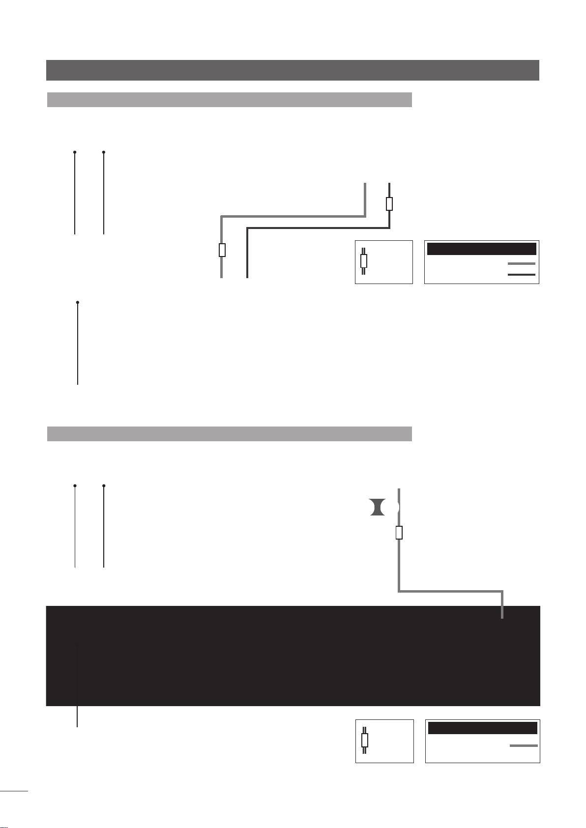
5 NAC 552 Controls and Connections
5.1 NAC 552 Front
source
bank
record
bank
volume
5.2 NAC 552 Rear
in 1 in 2 in 3
Inputs 1, 2 & 3
ch1
ch2
-ve
nc
nc
Inputs 4, 5 & 6
ch1
ch2
balance
in 4
in 5 in 6 in 8
Input 7
-ve
ch1
(out)
ch2
(out)
+ve
ch2
+ve
ch1
-ve
signal ground in 9
mono
mute
in 7 RC5 in
ch 1(L)
ch 1(L)
ch 2(R)
ch 2(R)
source and record
selection
NAC 552PS
NAC 552PS
E4

NAC 552 Preamplifier
5.3 NAC 552 Connected to NAC 552PS
Note: For best performance the Burndy and 5 pin DIN
cables should be run as close together as possible.
additional signal output
mains input
and fuse
6 NAC 552/NAC 552PS Specification
Input Sensitivities: 75mV, 47kΩ
Overload Margins: 40dB
(all inputs all audio frequencies).
Main Output Level: 0.775V, <50Ω
Tape Output Level: 75mV, 600Ω
Auxiliary Power Outputs: For Naim phono stage
Dimensions (H x W x D): Both 87 x 432 x 314mm
Weight: NAC 552 - 12.9kg
NAC 552PS - 13.9kg
Mains Supply (NAC 552PS): 100V, 115V or 230V, 50/60Hz
to mono or dual mono
power ampliers
cable
direction
marker
to stereo power
ampliers
Interconnect Cables
NAC 552 Burndy
240° 5 to 5 pin DIN
E5

NAC 252 Preamplifier
7 NAC 252 Introduction and Installation
The NAC 252 preamplifier does not incorporate an internal power supply and can be used
only in conjunction with the Supercap power supply. Diagram 8.3 illustrates connection of
the NAC 252 to its power supply.
The preamplifier and power supply should be installed on a dedicated equipment
stand intended for the purpose. Do not stand either directly on top of another item of
equipment. Care should be taken to ensure that the preamplifier is level.
The preamplifier and power supply should be installed in their final locations before
connecting cables or switching on. Ensure that power amplifiers are switched off and the
preamplifier volume is turned down before the power supply is switched on. The power
button is located on the power supply front panel.
The power supply is heavy and care should be taken when lifting or moving it. Make sure
that the surface on which it is to be placed can support its weight.
The following Section 7 paragraphs describe installation features and functions specific to
the NAC 252. Operational features common to all preamplifiers and integrated amplifiers
are described in Section 28.
7.1 Source Inputs and Record Outputs
The input selection buttons arranged along the upper bank
select the source signal to be routed to the power amplifier
and the loudspeakers. Below them, in the lower bank, are a
corresponding array of buttons which select the signal to be
routed to the preamplifier’s record outputs.
These separate source and record sections enable one
source (a CD player, for example) to be listened to whilst
the output from another (say, the tuner) is simultaneously
selected for recording.
Note: It is possible to lock the record controls and prevent
accidental de-selection during recording. Record-lock is
switched on or off by pressing the source mono button four
times within six seconds.
7.2 Input Socket Assignment
The NAC 252 has six DIN input sockets and two alternative
pairs of RCA Phono sockets. The RCA Phono sockets can be
assigned individually to the CD and AUX 2 input buttons in
place of the DIN sockets.
Input assignment setup is accessed through the NAC
252 program mode. To switch into (or exit from) program
mode press and hold the prog key on the remote handset
(in preamplifier mode). Program mode is indicated by a
flashing indicator on the front panel volume control and the
record selection indicators extinguishing.
Note: If no function is operated within five minutes of
entering program mode the NAC 252 will return to normal
mode automatically.
Once in program mode press and hold the remote handset
1 key to select or de-select the RCA Phono socket input for
CD, and the remote handset 6 key to select or de-select
the RCA Phono socket input for AUX 2. The corresponding
front panel input buttons can similarly be used to select or
de-select the RCA Phono socket inputs. The appropriate
input button indicator will flash three times on selection of
the RCA Phono option and once on selection of the DIN
option.
To exit from program mode press and hold the prog key on
the handset until the record select indicators are restored
and the volume indicator stops flashing.
Operational features
common to all
preamplifiers and
integrated amplifiers
are described in
Section 28
E6
8 NAC 252 Controls and Connections
8.1 NAC 252 Front
volume
balance
source
bank
record
bank
mono
mute
source and record
selection

NAC 252 Preamplifier
in 5
8.2 NAC 252 Rear
aux 1
in 6
aux 2
supercap RC5 in
supercap
in 4
in 1 cdin 2
Inputs 1, 2 & 6
ch1
ch2
-ve
tuner
nc
nc
in 3
tape
Inputs 3, 4 & 5
ch1
ch2
av
-ve
signal
ground
ch1
(out)
ch2
(out)
in 6 (alternative)
Input 6
(alternative)
+ve
ch2
8.3 NAC 252 Connected to Supercap
Note: For best performance the Burndy and 5 pin DIN cables
should be run as close together as possible.
-ve
+ve
ch1
cd/RCA Phono
ch1(L)
ch2(R)
Note: The NAC 252 AUX 2 input is provided with two sockets.
The lower socket, fitted on delivery with a blanking cover, is
intended for use with a Naim Audio RCA Phono stage and
incorporates an appropriate DC power supply. The two
sockets must not be used simultaneously.
Note: The RS232/comms interface is an optional upgrade.
It can be specified at time of order or fitted retrospectively.
Contact your local representative or Naim Audio directly for
further information.
aux 2/RCA Phono
ch1(L)
ch2(R)
RS232
interface
mains input
and fuse
9 NAC 252/Supercap Specification
Input Sensitivities: 75mV, 47kΩ
Overload Margins: 40dB
(all inputs all audio frequencies)
Main Output Level: 0.775V, <50Ω
Tape Output Level: 75mV, 600Ω
Auxiliary Power Outputs: For Naim phono stage.
Dimensions (H x W x D): Both 87 x 432 x 314mm
Weight: NAC 252 - 7.0kg
Supercap - 11.6kg
Mains Supply (Supercap): 100V, 115V or 230V, 50/60Hz
additional signal output
to mono or dual mono
power ampliers
cable
direction
marker
to stereo power
ampliers
Interconnect Cables
NAC 252 Burndy
240° 5 to 5 pin DIN
E7

NAC 282 Preamplifier
10 NAC 282 Introduction and Installation
The NAC 282 preamplifier does not incorporate an internal power supply but must be
used in conjunction with either a Naim power amplifier incorporating a preamplifier
power output, or with an appropriate Naim power supply. A separate NAPSC supply that
provides power to the display and control circuits is supplied. Diagrams 11.3 and 11.4
illustrate two NAC 282 power supply options.
The preamplifier and power supply should be installed on a dedicated equipment
stand intended for the purpose. Do not stand either directly on top of another item of
equipment. Care should be taken to ensure that the preamplifier is level.
The preamplifier and any power supply should be installed in their final locations before
connecting cables or switching on. Ensure that the preamplifier volume is turned down
before switching on.
The following Section 10 paragraphs describe installation features and functions specific
to the NAC 282. Operational features common to all preamplifiers and integrated
amplifiers are described in Section 28.
Operational features
common to all
preamplifiers and
integrated amplifiers
are described in
Section 28
10.1 Source Inputs and Record Outputs
The input selection buttons arranged along the upper bank
select the source signal to be routed to the power amplifier
and the loudspeakers. Below them, in the lower bank, are a
corresponding array of buttons which select the signal to be
routed to the preamplifier’s record outputs.
These separate source and record sections enable one
source (a CD player, for example) to be listened to whilst
the output from another (say, the tuner) is simultaneously
selected for recording.
Note: It is possible to lock the record controls and prevent
accidental de-selection during recording. Record-lock is
switched on or off by depressing the source mono button
four times within six seconds.
10.2 Input Socket Assignment
The NAC 282 has six DIN input sockets and two alternative
pairs of RCA Phono sockets. The RCA Phono sockets can be
assigned individually to the CD and AUX 2 input buttons in
place of the DIN sockets.
11 NAC 282 Controls and Connections
Input assignment setup is accessed through the NAC
282 program mode. To switch into (or exit from) program
mode press and hold the prog key on the remote handset
(in preamplifier mode). Program mode is indicated by a
flashing indicator on the front panel volume control and the
record selection indicators extinguishing.
Note: If no function is operated within five minutes of
entering program mode the NAC 282 will return to normal
mode automatically.
Once in program mode press and hold the remote handset
1 key to select or de-select the RCA Phono socket input for
CD, and the remote handset 6 key to select or de-select
the RCA Phono socket input for AUX 2. The corresponding
front panel input buttons can similarly be used to select or
de-select the RCA Phono socket inputs. The appropriate
input button indicator will flash three times on selection of
the RCA Phono option and once on selection of the DIN
option.
To exit from program mode press and hold the prog key on
the handset until the record select indicators are restored
and the volume indicator stops flashing.
E8
11.1 NAC 282 Front
volume
balance
source
bank
record
bank
mono
mute
source and record
selection

NAC 282 Preamplifier
11.2 NAC 282 Rear
in 5
in 6
aux 1
aux 2
power supply/output option sockets
with link and blanking plugs tted
to NAPSC
RC5 in
in 1 cdin 2
Inputs 1, 2 & 6
ch1
ch2
-ve
tuner
nc
nc
in 4
in 3
av
tape
Inputs 3, 4 & 5
ch1
ch2
-ve
signal
in 6 (alternative) cd/RCA
ground
Input 6
ch1
(out)
ch2
(out)
(alternative)
+ve
ch2
+ve
ch1
-ve
Note: The NAC 282 AUX 2 input is provided with two sockets.
The lower socket, fitted on delivery with a blanking cover,
is intended for use with a Stageline or Prefix Phono stage
and incorporates an appropriate DC power supply. The two
sockets must not be used simultaneously.
Note: The RS232/comms interface is an optional upgrade.
It can be specified at time of order or fitted retrospectively.
Contact your local representative or Naim Audio directly for
further information.
11.3 NAC 282 Connected to Supercap and NAPSC
Phono
ch1(L)
ch2(R)
aux 2/RCA
Phono
ch1(L)
ch2(R)
to power
amplier
with
internal
power
supply
RS232
interface
mains input
and fuse
cable
direction
marker
Interconnect Cables
4 to 4 pin DIN
240° 5 to 5 pin DIN
additional signal output
to mono or dual mono
power ampliers
to stereo power
ampliers
E9

NAC 282 Preamplifier
11.4 NAC 282 Connected to Hi-Cap and NAPSC
to stereo power ampliers
mains input
and fuse
Note: Alternative upgrade schemes and product
combinations may be feasible. Contact your local
representative or Naim Audio directly for further information.
additional
signal output
to mono or dual
mono power
ampliers
cable
direction
marker
Interconnect Cables
240° 5 to 5 pin DIN
E10
12 NAC 282 Specification
Input Sensitivities: 75mV, 47kΩ
Overload Margins: 40dB
(all inputs all audio frequencies)
Main Output Level: 0.775V, <50Ω
Tape Output Level: 75mV, 600Ω
Auxiliary Power Outputs: For Naim phono stage.
Dimensions (H x W x D): 87 x 432 x 314mm
Weight: 7.0kg
Mains Supply (Hi-Cap): 100V, 115V or 230V, 50/60Hz

NAC 202 Preamplifier
13 NAC 202 Introduction and Installation
The NAC 202 preamplifier does not incorporate an internal power supply but must be
used in conjunction with either a Naim power amplifier incorporating a preamplifier
power output, or with an appropriate Naim power supply. A separate NAPSC supply that
provides power to the display and control circuits is also available. Diagram 14.3 illustrates
the NAC 202 connected to a Hi-Cap power supply.
The preamplifier and any power supply should be installed on a dedicated equipment
stand intended for the purpose. Do not stand either directly on top of another item of
equipment. Care should be taken to ensure that the preamplifier is level.
The preamplifier and any power supply should be installed in their final locations before
connecting cables or switching on. Ensure that the preamplifier volume is turned down
before switching on.
The following Section 13 paragraphs describe installation features and functions specific
to the NAC 202. Operational features common to all preamplifiers and integrated
amplifiers are described in Section 28.
Operational features
common to all
preamplifiers and
integrated amplifiers
are described in
Section 28
13.1 Input Sockets and Assignment
The input selection buttons select the source input signal to
be routed to the power amplifier and the loudspeakers.
The NAC 202 has six DIN input sockets and two alternative
pairs of RCA Phono sockets. The RCA Phono sockets can be
assigned individually to the CD and AUX 2 input buttons in
place of the DIN sockets.
Input assignment setup is accessed through the NAC
202 program mode. To switch into (or exit from) program
mode press and hold the prog key on the remote handset
(in preamplifier mode). Program mode is indicated by a
flashing indicator on the front panel volume control.
Note: If no function is operated within five minutes of
entering program mode the NAC 202 will return to normal
mode automatically.
14 NAC 202 Controls and Connections
Once in program mode press and hold the remote handset
1 button to select or de-select the RCA Phono socket
input for CD, and the remote handset 6 button to select
or de-select the RCA Phono socket input for AUX 2. The
corresponding front panel input buttons can similarly be
used to select or de-select the RCA Phono socket inputs. The
appropriate input button indicator will flash three times on
selection of the RCA Phono option and once on selection of
the DIN option.
To exit from program mode press and hold the prog key on
the remote until the volume indicator stops flashing.
13.2 Record Mute
In order to minimise power consumption and improve sound
quality the NAC 202 record output circuit can be muted.
To engage or disengage record mute press the front panel
mon button followed by the front panel mute button. The
mute button indicator will illuminate when record mute is
engaged and extinguish when it is disengaged. Record
mute can also be engaged and disengaged from the
remote handset using the mon and mute keys.
14.1 NAC 202 Front
volume
mon
mute
source selection
E11

NAC 202 Preamplifier
signal
14.2 NAC 202 Rear
g’nd
in 6
(alternative)
power supply/output option sockets
with link and blanking plugs tted
to NAPSC
RC5 in
in 1 cdin 2
Inputs 1, 2 & 6
ch1
ch2
-ve
tuner
nc
nc
in 4
in 3
av
tape
Inputs 3, 4 & 5
ch1
ch2
-ve
in 5
aux 1
ch1
(out)
ch2
(out)
in 6
aux 2
(alternative)
+ve
ch2
Input 6
-ve
+ve
ch1
Note: The NAC 202 AUX 2 input is provided with two sockets.
The upper socket, fitted on delivery with a blanking cover,
is intended for use with a Stageline or Prefix Phono stage
and incorporates an appropriate DC power supply. The two
sockets must not be used simultaneously.
Note: The RS232/comms interface is an optional upgrade.
It can be specified at time of order or fitted retrospectively.
Contact your local representative or Naim Audio directly for
further information.
14.3 NAC 202 Connected to Hi-Cap and NAPSC
cd/RCA
Phono
ch1(L)
ch2(R)
aux 2/RCA
Phono
ch1(L)
ch2(R)
to power
amplier
with
internal
power
supply
RS232
interface
E12
mains input
and fuse
cable
direction
marker
to stereo power ampliers
additional
signal output
Interconnect Cables
4 to 4 pin DIN
240° 5 to 5 pin DIN
to mono or dual
mono power
ampliers
15 NAC 202 Specification
Input Sensitivities: 75mV, 47kΩ
Overload Margins: 40dB
(all inputs all audio frequencies)
Main Output Level: 0.775V, <50Ω
Tape Output Level: 75mV, 600Ω
Auxiliary Power Outputs: For Naim phono stage.
Dimensions (H x W x D): 87 x 432 x 314mm
Weight: 7.0kg
Mains Supply (Hi-Cap): 100V, 115V or 230V, 50/60Hz

NAC 152 XS Preamplifier
16 NAC 152 XS Introduction and Installation
The NAC 152 XS preamplifier does not incorporate an internal power supply but must be
used in conjunction with either a Naim power amplifier incorporating a preamplifier power
output, or with an appropriate Naim power supply. Diagram 17.3 illustrates the NAC 152 XS
connected to a FlatCap XS power supply.
The preamplifier and any power supply should be installed on a dedicated equipment
stand intended for the purpose. Do not stand either preamplifier or power supply directly
on top of another item of equipment. Ensure that the preamplifier is level.
The preamplifier and any power supply should be installed in their final locations before
connecting cables or switching on. Ensure that the preamplifier volume is turned down
before switching on.
The following Section 16 paragraphs describe installation features and functions specific
to the NAC 152 XS. Operational features common to all preamplifiers and integrated
amplifiers are described in Section 28.
Operational features
common to all
preamplifiers and
integrated amplifiers
are described in
Section 28
16.1 Audio Inputs
The input selection buttons select the source input signal
to be routed to the preamplifier outputs and the power
amplifier.
The NAC 152 XS has six DIN input sockets and five pairs
of RCA Phono sockets. The RCA Phono sockets are
permanently connected in parallel with their respective DIN
sockets. RCA Phono and DIN sockets for the same input
should not be connected simultaneously.
Note: The aux2 DIN input socket carries a power supply
output voltage appropriate for a Naim phono preamplifier.
A 3.5mm stereo Jack input socket suitable for an iPod (or
alternative portable music player) is also provided on the
NAC 152 XS front panel. This input is connected in parallel
with the aux 1 DIN and RCA Phono sockets.
Insertion of a plug into the front panel socket will
automatically switch the preamplifier to that input. Removal
of the plug will return the amplifier to the previously selected
input. If a different input is selected while a plug is inserted,
removal of the plug will not cause the input to change.
16.2 Audio Outputs
The NAC 152 XS provides subwoofer and line level outputs,
each via a pair of RCA Phono sockets.
The line level output simply reflects the selected input signal
while the subwoofer output is a duplicate of the main
preamplifier output (i.e it is affected by the preamplifier
volume control).
16.3 Power Supply Upgrades
The NAC 152 XS can be powered by a Naim power
amplifier incorporating a preamplifier power supply or its
performance upgraded through the connection of one or
more external power supplies. Power supply upgrades can
be carried out in stages:
Stage 1 is to connect an i-Supply, Flatcap, Hi-Cap or
Supercap power supply to the NAC 152 XS Upgrade 1
socket. The link/blanking plug inserted in the Link 1 socket
must be removed.
Stage 2 is to connect a Flatcap, Hi-Cap or Supercap power
supply to the NAC 152 XS Upgrade 2 socket. The link plug
fitted to this socket must be removed. With a second power
supply added, the NAC 152 XS no longer requires a power
supply from the power amplifier, which should now be
connected via the Stage 2 power supply.
Diagrams illustrating both power supply upgrade stages are
shown in Section 17.
Note: Link plugs must only be inserted in the sockets from
which they were removed and unused power supply
sockets must not be used for any other purpose. Incorrect
use of link plugs and power supply sockets risks significant
damage to the power supply or preamplifier.
Note: A wide variety of different power supply schemes are
potentially possible for the NAC 152 XS, including the use of
one Flatcap for both upgrade stages. Your local retailer will
be able to advise on the best scheme for your particular
system.
Note: The NAPSC power supply cannot be used with the
NAC 152 XS.
iPod is a trademark of Apple Inc., registered in the U.S. and other countries
E13

NAC 152 XS Preamplifier
17 NAC 152 XS Controls and Connections
17.1 NAC 152 XS Front
volume
17.2 NAC 152 XS Rear
cd in
tuner in
phono
ch1
ch2
phono
cd intuner in hdd
cd, tun, hdd, av,
and aux inputs
-ve
hdd in
phono
in
Alternative aux 2
+ve
nc
ch2
nc
av in
phono
av
in
aux 1
input
-ve
aux 1 in
phono
to power amplier with internal power supply
aux 2
in
in
+ve
ch1
signal ground
aux 2 in & power out
(cover tted)
front panel
input socket
to power amplier with
internal power supply
power supply upgrade
link plugs tted
Note: The NAC 152 XS AUX 2 input is provided with two
sockets. The right hand socket (fitted on delivery with a
blanking cover), is intended for use with a Stageline or
SuperLine phono stage and incorporates an appropriate
DC power supply. The two sockets must not be used
simultaneously.
mute source selection
line
output
subwoofer
output
remote in
RS232
interface
Note: The NAC 152 XS features various technologies to
reduce microphonic effects. Some movement of the board
and sockets when connecting and disconnecting cables is
normal.
E14 E15
Note: The RS232/comms interface is an optional upgrade.
It can be specified at time of order or fitted retrospectively.
Contact your local representative or Naim Audio directly for
further information.
cable
direction
marker
Interconnect Cables
4 to 4 pin DIN
240° 5 to 5 pin DIN

NAC 152 XS Preamplifier
17.3 NAC 152 XS Connected to FlatCap XS Power Supply (stage 1 upgrade)
to power amplier with
internal power supply
power
switch
mains input
and fuse
for preamplier stage 2
upgrade, CD5 XS, Headline
or phono stage. Additional
interconnects required.
cable
direction
marker
Interconnect Cables
4 to 4 pin DIN
240° 5 to 5 pin DIN
E15

NAC 152 XS Preamplifier
17.4 NAC 152 XS Connected to Hi-Cap and FlatCap XS Power Supplies (stage 2 upgrade)
to stereo power ampliers
mains input
and fuse
power
switch
mains input
and fuse
additional
signal output
to mono or dual
mono power
ampliers
for CD5 XS, Headline or
phono stage. Additional
interconnects required.
cable
direction
marker
Interconnect Cables
4 to 4 pin DIN
240° 5 to 5 pin DIN
E16
18 NAC 152 XS Specification
Input Sensitivities: 130mV, 47kΩ
Overload Margins: 35dB
(all inputs all audio frequencies)
Main Output Level: 0.775V, <50Ω
Line Output Level: 130mV, 600Ω
Auxiliary Power Outputs: For Naim phono stage.
Dimensions (H x W x D): 70 x 432 x 301mm
Weight: 3.9kg
Mains Supply (FlatCap XS): 100V, 115V or 230V, 50/60Hz

SUPERNAIT Integrated Amplifier
19 SUPERNAIT Introduction and Installation
The Supernait should be installed on a dedicated equipment stand intended for the
purpose. Do not stand it directly on top of another item of equipment. Care should
be taken to ensure that it is level. The amplifier should be installed in its final location
before connecting cables or switching on. Ensure that the volume is turned down before
switching on.
A variety of power supply upgrade, alternative preamplifier and alternative or additional
power amplifier options are possible for the Supernait. Diagrams illustrating the connection
of some of these are shown in Section 20.
The following Section 19 paragraphs describe installation features and functions specific
to the Supernait. Operational features common to all preamplifiers and integrated
amplifiers are described in Section 28.
Operational features
common to all
preamplifiers and
integrated amplifiers
are described in
Section 28
19.1 Source Input Selection and Assignment
The input selection buttons arranged along the upper bank
select the source signal to be routed to the power amplifier
and the loudspeakers. The six buttons are labelled cd, tuner,
tape, av, aux1 and aux2.
Each input button may be assigned to analogue inputs
(via DIN, RCA Phono or 3.5mm jack sockets), or to digital
inputs via RCA Phono coaxial, “Toslink” or “mini-toslink”
optical sockets. The default settings and the assignment
setup procedure are detailed in Sections 19.2 and 19.3
respectively.
19.1.1 Analogue Inputs
The first four selection buttons (cd, tuner, tape and av) can
each be assigned to both a DIN input socket and a pair of
RCA Phono input sockets on the rear panel. The DIN and
Phono sockets for each input are internally wired in parallel
and should not be connected simultaneously.
The aux1 and aux2 selection buttons can each be assigned
to a pair of RCA Phono input sockets and a DIN input socket
on the rear panel respectively.
Note: The aux2 DIN input socket carries a power supply
output voltage appropriate for a Naim phono preamplifier.
19.1.2 Digital Inputs
The Supernait additionally provides four S/PDIF digital input
sockets - 2 RCA Phono coaxial and 2 “Toslink” optical - on
the rear panel. Any input selection button can be assigned
to one of these sockets.
Note: The digital inputs support stereo PCM audio only. If the
digital signal contains anything other than stereo PCM audio
(Dolby or DTS encoded programme material for example)
all outputs will be muted.
19.1.3 Front Panel Combined Input
An auxiliary front panel input socket is also provided. This
socket is a 3.5mm analogue “jack” input combined with a
digital “mini-Toslink” optical socket. The analogue input is
wired internally in parallel with the rear panel aux1 input and
the two must not be connected simultaneously.
The front panel input (analogue or digital) is automatically
selected (and the aux1 selection button automatically
assigned to it), whenever a plug is inserted in the socket.
Note: The Supernait is able to differentiate a digital source
from an analogue one at the front panel input if the digital
source is working when the plug is inserted.
Input selection will revert to that previously selected when
the front panel input plug is removed.
19.2 Default Input Selection Button and Input Socket Assignment
Input Selection Input Socket Input Socket
Button Assignment Type
cd Analogue Input 1 DIN/RCA Phono
tuner
Analogue Input 2 DIN/RCA Phono
tape
Digital Input 1 RCA Phono Coax
av
Analogue Input 4 DIN/RCA Phono
aux1
Digital Input 2 “Toslink” Optical
(See Note)
aux2
Analogue Input 6 DIN (with Naim phono stage power supply)
Note: Any plug inserted into the front panel socket will automatically provoke selection of this
input (digital or analogue) and will automatically assign it to the aux1 selection button.
E17

SUPERNAIT Integrated Amplifier
19.3 Digital Input Assignment
The default digital input socket assignment illustrated in
Table 19.2 may be changed if desired. Each selection
button may be assigned to any one of the four rear panel
digital input sockets.
Input assignment setup is accessed through the Supernait
program mode. To switch into (or exit from) program mode
press and hold the prog key on the remote handset (in
preamplifier mode). Program mode is indicated by a
flashing indicator on the front panel volume control.
Note: If no function is operated within five minutes of
entering program mode the Supernait will return to normal
mode automatically.
Once in program mode, to assign a digital input socket, first
press the required input selection button. Then, press one
of the record selection buttons to assign the desired digital
input. The record selection buttons assign digital inputs as set
out in the following table:
Record Select Button Digital Input Selection
cd (assigns) digital 1 (coaxial)
tuner (assigns) digital 2 (optical)
tape (assigns) digital 3 (coaxial)
av (assigns) digital 4 (optical)
As an example, to assign the tuner input selection button to
digital input 4 proceed as follows.
i) Enter program mode.
ii) Press the tuner input selection button.
iii) Press the av record selection button (which will illuminate).
iv) Exit program mode.
To return an input selection button to its default analogue
input, repeat the assignment procedure.
For example, to return the tuner input selection button to its
analogue input socket.
i) Enter program mode.
ii) Press the tuner input selection button.
iii) Press the av (illuminated) record selection button (which
will extinguish).
iv) Exit program mode.
19.4 Record Outputs
The selection buttons arranged along the lower bank select
the source signal to be routed to the Supernait’s record
outputs.
These separate source and record sections enable one
source (a CD player, for example) to be listened to whilst
the output from another (say, the tuner) is simultaneously
selected for recording.
Note: Simultaneous and independent listen and record is not
possible with two digital sources.
19.5 Speaker Outputs
A stereo set of speaker connection sockets is provided on
the rear panel. Custom Naim Audio loudspeaker connectors
are supplied to make the connection and in order to
comply with current European safety regulations these
should always be used. Naim Audio speaker cable will
provide the best results; however, a wide range of speaker
cable types can be used without risk of damage to the
amplifier.
Ensure when connecting speakers that they are “in phase”.
That is, the positive and negative connection orientation
at both the speaker and amplifier ends of the cable is the
same for both channels.
19.6 Headphone Output
A 3.5mm headphone socket is provided on the front panel.
Insertion of a headphone plug will automatically switch on
the headphone amplifier and mute the speaker outputs
unless the Supernait is set up not to mute.
To prevent (or re-enable) automatic speaker muting, enter
program mode and press the record aux2 selection button.
19.7 Auxiliary Inputs and Outputs
A bi-amp out (preamplifier output) DIN socket is provided
on the rear panel to enable an external upgrade power
amplifier or second (bi-amp) power amplifier to be used.
Note: Bi-amp out is the preferred socket for all external
power amplifier connections.
Also provided are separate pre-amp out and power-amp
in sockets. In normal use these sockets are connected by
an external link plug. The link plug should be removed only
if a power supply upgrade is to be used or an alternative
preamplifier is to use the Supernait power amplifier section.
Diagrams 20.3 to 20.5 illustrate use of these sockets.
When an external preamplifier is connected to the Supernait
power-amp in socket, a fault will initially be indicated by the
source mute button flashing. To clear the fault, press and
hold the flashing source mute button. This will un-mute the
power amplifier and turn off the display and volume and
balance indicators.
The Supernait provides an unfiltered analogue stereo
subwoofer output via a pair of RCA Phono sockets.
Note: The subwoofer output is a duplicate of the
preamplifier output. No low-pass filtering is applied.
19.8 Power Supply Upgrades
The Supernait preamplifier section can be upgraded
through the connection of an external Flatcap, Hi-Cap or
Supercap power supply. Diagrams illustrating power supply
upgrades are shown in the following section. The Supernait
and external power supply must be switched off when
connections are made. Switch on the external power supply
and then the Supernait when all connections are complete.
E18

SUPERNAIT Integrated Amplifier
19.9 General Connections Notes
The Supernait negative input and output connections for
each channel are common. The mains earth (ground)
should always be connected regardless of what other
equipment is used in conjunction with the amplifier. The
mains earth only grounds the case and the electrostatic
20 SUPERNAIT Controls and Connections
20.1 SUPERNAIT Front
volume
balance
screen within the transformer, and is not connected to the
signal negative. In order to avoid hum loops, the signal
negative of the whole system should be connected to the
mains earth (ground) in one place.
source and record
selection
source
bank
record
bank
mute
combined
analogue and
digital input
headphone
output
20.2 SUPERNAIT Rear
power
ch1
ch2
ch2
mains
input
and fuse
cd and tuner
Inputs
-ve
pre-amp out for
bi-amp
ch1
-ve
nc
RS232
interface
nc
nc
speaker
tape and av
Inputs
ch1
ch2
left
-ve
ch1
(out)
ch2
(out)
right
speaker
aux 2 input
+ve
ch2
-ve
+ve
ch1
analogue
digital
inputs
outputs
Phono RCA
inputs
RC5 in/out
signal ground
power amp in and
preamp out. Link
plug tted.
aux 2
in &
power
out
av in
& out
tape
in &
out
Note: The RS232 interface is an optional upgrade. It can be
specified at time of order or fitted retrospectively. Contact
your local representative or Naim Audio directly for further
information.
Note: The link plug should be removed only if a power supply
upgrade is to be used or an alternative preamplifier is to use
the Supernait power amplifier section. It should remain fitted
in all other circumstances.
tunertapeavaux1tapesubbi-amp1 2 3 4
cd
tuner incd in
E19
SUPERNAIT Integrated Amplifier
20.3 SUPERNAIT Connected to Hi-Cap Power Supply
power
mains
input
and fuse
mains input
and fuse
20.4 SUPERNAIT Connected to NAP 200 Power Amplifier
cable
direction
marker
Interconnect Cables
4 to 4 pin DIN
240° 5 to 5 pin DIN
E20
power
mains
input
and fuse
mains input
and fuse
cable
direction
marker
Interconnect Cables
4 to 4 pin DIN

SUPERNAIT Integrated Amplifier
20.5 SUPERNAIT Connected to Hi-Cap Power Supply and NAP 200 Power Amplifier
power
mains
input
and fuse
mains input
and fuse
cable
direction
marker
Interconnect Cables
4 to 4 pin DIN
240° 5 to 5 pin DIN
mains input
and fuse
21 SUPERNAIT Specification
Input Sensitivities: 75mV, 47kΩ
Overload Margins: 40dB
(all inputs all audio frequencies)
Preamp Output Level: 0.775V, <50Ω
Tape Output Level: 75mV, 600Ω
Power Output: Continuous 80 Watts per
channel into 8 Ohms
Auxiliary Power Outputs: For Naim phono stage
Quiescent Consumption:
Dimensions (H x W x D): 87 x 432 x 314mm
Weight: 12.8kg
Mains Supply: 100V, 115V or 230V, 50/60Hz
10VA
E21

NAIT XS Integrated Amplifier
22 NAIT XS Introduction, Installation and Connections
The NAIT XS should be installed on a dedicated equipment stand intended for the
purpose. Do not stand it directly on top of another item of equipment. Care should
be taken to ensure that it is level. The amplifier should be installed in its final location
before connecting cables or switching on. Ensure that the volume is turned down before
switching on.
A variety of power supply upgrade, alternative preamplifier and alternative or additional
power amplifier options are possible for the NAIT XS. Diagrams illustrating the connection
of some of these are shown in Section 23. Contact your local retailer or distributor for
advice on further alternative connection schemes.
The NAIT XS incorporates an AV Bypass switch on its rear panel. The switch should only
be set to “On” if the amplifier is to be used in conjunction with an AV processor in a
home theatre system. In all other installations the AV Bypass switch should be set to “Off”.
Speaker and/or amplifier damage may occur if a signal is inadvertently connected to the
NAIT XS av input while the AV Bypass switch is “On”.
Operational features common to all preamplifiers and integrated amplifiers are described
in Section 28.
Operational features
common to all
preamplifiers and
integrated amplifiers
are described in
Section 28
22.1 Mains Power Connection
Connect the NAIT XS to a mains power socket using either
the mains cable supplied or a Naim Power-Line.
22.2 Signal Inputs
The NAIT XS front panel input buttons select the source input
signal to be routed to the integral power amplifier and the
loudspeakers. The six buttons are labelled cd, tuner, hdd, av,
aux 1 and aux 2.
The cd, tuner, hdd and av input buttons select parallel DIN
and RCA phono input sockets on the rear panel.
Note: The hdd and av sockets carry both inputs and outputs.
See Section 22.4 for more information.
The aux 1 input button corresponds to a pair of RCA phono
sockets on the rear panel and a parallel 3.5mm stereo jack
socket on the front panel. Insertion of a plug into the front
panel aux 1 socket will automatically switch the amplifier
to that input. Removal of the plug will return the amplifier to
the previously selected input. If a different input is selected
while a plug is inserted removal of the plug will not cause
the input to change.
The aux 2 input button corresponds to a DIN input socket
on the rear panel. The aux 2 DIN socket also carries a
power supply output suitable to power a Naim Stageline or
SuperLine phono preamplifier.
Note: For optimum sound quality DIN sockets should be used
in preference to RCA phono sockets.
Note: Where an input has DIN or Phono socket options only
one should be connected at any one time.
Always use high quality interconnect cables to connect
sources to inputs. The Naim Hi-Line will produce the best
results.
22.3 Speaker Outputs
A set of stereo speaker connection sockets is provided on
the rear panel. Custom Naim loudspeaker connectors are
supplied to make the connection and in order to comply
with current European safety regulations these should always
be used. Naim speaker cable will provide the best results,
however, a wide range of speaker cable types can be used
without risk of damage to the amplifier.
Ensure when connecting speakers that they are “in phase”.
That is, the positive and negative connection orientation
at both the speaker and amplifier ends of the cable is the
same for both channels.
22.4 AV and hdd Inputs and Outputs
The NAIT XS av and hdd inputs have associated outputs that
enable the selected input signal to be routed externally; to
an audio recording component for example.
Note: The av or hdd outputs will be muted if their
corresponding inputs are selected.
22.5 AV Bypass
The NAIT XS can be integrated within a multi-channel home
theatre system, driving the front left and right channel
speakers, by engaging its AV Bypass mode. AV Bypass mode
enables a home theatre processor to take over volume
control of signals connected to the NAIT XS av input. It is
engaged using the switch on the rear panel. The NAIT XS
volume control indicator will extinguish when AV Bypass
mode is engaged and the av input is selected. The remote
handset volume control will also be disabled.
Note: The AV Bypass feature must be used with care. It
bypasses the NAIT XS volume control leaving any signal
connected to the av input to be passed to the speakers at
full volume.
Note: The mute function is disabled when AV Bypass is
engaged.
E22

NAIT XS Integrated Amplifier
22.6 Auxiliary Inputs and Outputs
The NAIT XS incorporates pre-amp out and power-amp in
sockets on its rear panel. In normal use these sockets are
connected by a link plug. The link plug should be removed
only in the following circumstances:
• A power supply upgrade is to be used.
• An alternative preamplifier is to use the NAIT XS power
amplifier section.
• An alternative power amplifier is to use the NAIT XS
preamplifier section.
Diagrams 23.3 and 23.4 illustrate use of these sockets.
When an external preamplifier is connected to the NAIT XS
power-amp in socket, a fault will initially be indicated by the
mute button flashing. To clear the fault, press and hold the
flashing mute button. This will un-mute the amplifier and turn
off the display and volume indicator.
The NAIT XS provides an unfiltered analogue stereo
subwoofer output via a pair of RCA phono sockets.
Note: The subwoofer output is a duplicate of the
preamplifier output. No low-pass filtering is applied.
22.7 Power Supply Upgrades
The NAIT XS preamplifier section can be upgraded through
the connection of an external Flatcap, Hi-Cap or Supercap
power supply. Diagrams illustrating power supply upgrades
are shown in Section 23. The NAIT XS and external power
supply must be switched off when connections are made.
Switch on the external power supply first followed by the
NAIT XS when all connections are complete.
22.8 General Connections Notes
The NAIT XS negative input and output connections for each
channel are common. The mains earth (ground) should
always be connected regardless of what other equipment is
used in conjunction with the amplifier. The mains earth only
grounds the case and the electrostatic screen within the
transformer, and is not connected to the signal negative. In
order to avoid hum loops, the signal negative of the whole
system should be connected to the mains earth (ground) in
one place.
A signal ground connection is fitted to the NAIT XS rear
panel. This is intended to be used to connect a turntable
pick-up arm signal earth only.
23 NAIT XS Controls and Connections
23.1 NAIT XS Front
volume
aux 1 input socket
source selection
mute
E23

NAIT XS Integrated Amplifier
23.2 NAIT XS Rear
remote in
subwoofer
out
aux 1
input
av
in
hdd
in
tuner
in
cd
in
power
mains
input
and fuse
cd and tuner
Inputs
ch1
ch2
-ve
RS232
interface
nc
nc
left
speaker
hdd and av
Inputs/outputs
ch1
ch2
-ve
speaker
ch1
(out)
ch2
(out)
right
ch2
aux 2 input
+ve
-ve
signal
ground
+ve
ch1
power amp in
AV
bypass
switch
and preamp
out. Link plug
Note: The RS232 interface is an optional upgrade. It can
be specified at time of order or fitted retrospectively.
Contact your local representative or Naim directly for further
information.
Note: The link plug should be removed only if a power
supply upgrade is to be used, an alternative preamplifier is
to use the NAIT XS power amplifier section, or an alternative
power amplifier is to use the NAIT XS preamplifier section. It
Note: The Nait XS features various technologies to reduce
should remain fitted in all other circumstances.
microphonic effects. Some movement of the board and
sockets when connecting and disconnecting cables is
normal.
23.3 NAIT XS Connected to FlatCap XS Power Supply
tted.
aux 2
in &
power
out
av in
& out
hdd
in &
out
tuner incd in
E24
power
power
mains input
and fuse
mains input
and fuse
Note: The NAIT XS should remain connected
to mains power at all times.
cable
direction
marker
Interconnect Cables
4 to 4 pin DIN
240° 5 to 5 pin DIN

NAIT XS Integrated Amplifier
23.4 NAIT XS Connected to Hi-Cap Power Supply and NAP 200 Power Amplifier
power
mains input
and fuse
mains input
and fuse
mains input
and fuse
Note: The NAIT XS should remain connected to
mains power at all times.
cable
direction
marker
Interconnect Cables
4 to 4 pin DIN
240° 5 to 5 pin DIN
24 NAIT XS Specification
Input Sensitivities: 130mV, 47kΩ
Overload Margins: 34dB
(all inputs all audio frequencies)
Preamp Output Level: 0.775V, <50Ω
Line Output Level: 130mV, 600Ω
Power Output: Continuous 60 Watts per
channel into 8 Ohms
Auxiliary Power Outputs: For Naim phono stage
Quiescent Consumption:
Dimensions (H x W x D): 70 x 432 x 301mm
Weight: 8.6kg
Mains Supply: 100V, 115V or 230V, 50/60Hz
20VA
E25

NAIT 5i Integrated Amplifier
25 NAIT 5i Introduction and Installation
The Nait 5i should be installed on a dedicated equipment stand intended for the
purpose. Do not stand it directly on top of another item of equipment. Care should
be taken to ensure that it is level. The amplifier should be installed in its final location
before connecting cables or switching on. Ensure that the volume is turned down before
switching on.
The following Section 25 paragraphs describe installation features and functions specific
to the Nait 5i. Operational features common to all preamplifiers and integrated amplifiers
are described in Section 28.
25.1 Inputs
The front panel input selector buttons select the source
input signal to be routed to the power amplifier and the
loudspeakers. The four buttons are labelled cd, tuner, hdd
and av. Each input button corresponds to a pair of rear
panel RCA Phono input sockets. The cd and tuner inputs
are additionally provided with alternative DIN sockets. These
should be used in preference to the RCA Phono sockets if
practical. Do not connect both the DIN and RCA Phono
sockets of one input simultaneously.
A 3.5mm stereo Jack input socket suitable for an iPod* (or
alternative portable music player) on is also provided on
the Nait 5i front panel.
Insertion of a plug into the front panel socket will
automatically switch the preamplifier to that input. Removal
of the plug will return the amplifier to the previously selected
input.
Note: The mute function will not operate when the front
panl input is in use.
25.2 Outputs
A stereo set of speaker connection sockets is provided on
the rear panel. The sockets can accept standard 4mm
plugs, but to comply with European legislation the Naim
connectors supplied should be used. Naim Audio speaker
cable will provide the best results; however, a wide range of
speaker cable types can be used without risk of damage to
the amplifier.
Ensure when connecting speakers that they are “in phase”.
That is, the positive and negative connection orientation
at both the speaker and amplifier ends of the cable is the
same for both channels.
The hdd output always carries the selected input signal.
Operational features
common to all
preamplifiers and
integrated amplifiers
are described in
Section 28
26 NAIT 5i Controls and Connections
26.1 NAIT 5i Front
volume
front panel
input socket
source selection
E26

NAIT 5i Integrated Amplifier
26.2 NAIT 5i Rear
power
Note: The Nait 5i features various technologies to reduce
microphonic effects. Some movement of the board and
sockets when connecting and disconnecting cables is
normal.
mains
input
and fuse
left
speaker
right
speaker
27 NAIT 5i Specification
Input Sensitivities: 225mV, 20kΩ
Overload Margins: 35dB
(all inputs all audio frequencies)
Tape Output Level: 225mV, 100Ω
Power Output: Continuous 50 Watts per
channel into 8 Ohms
Quiescent Consumption:
Dimensions (H x W x D): 70 x 432 x 301mm
Weight: 6.4kg
Mains Supply: 100V, 115V or 230V, 50/60Hz
10VA
av in
hdd in
hdd out
tuner input (RCA Phono)
tuner input (DIN)
CD input (RCA
Phono)
cd and tuner
ch1
ch2
CD input (DIN)
Inputs
nc
nc
-ve
E27

Preamplifier and Integrated Amplifier Operation
28 Preamplifier and Integrated Amplifier Operation
Many operational and control features of Naim preamplifiers and integrated amplifiers
are common to all and are based on a similar user interface. This section of the manual
describes those features and the user interface, drawing attention to differences between
products where they occur. Table 28.10 sets out some variations in user interface between
products.
Front panel controls are duplicated on the remote control handset which may also
provide some extra functions. See Sections 29 and 30 for more information.
For the purposes of brevity the term preamplifier in the following paragraphs can be taken
also to mean integrated amplifier.
28.1 Automatic Input Switching
With Automatic Input Switching engaged the appropriate
source input will be selected as soon as any handset function
for that (Naim) source component is operated. For example,
if the tuner input is selected and the cd play key is pressed on
the handset, the preamplifier will automatically switch to the
cd input. Automatic Input Switching can be programmed to
operate on any combination of the cd, av, hdd and tuner
input buttons (and sockets to which they are assigned).
To enable Automatic Input Switching, first switch the
preamplifier into program mode by pressing and holding
the handset prog key (with the handset in preamplifier
mode). The front panel source mono/mon button (NAC
202 mon and NAC 152 XS mute buttons, Supernait record
mute button, Nait XS mute button and Nait 5i hdd button)
will illuminate if automatic switching is already enabled. If it
is not enabled it can be switched on by pressing the same
button.
With automatic switching enabled, pressing the button
again will reveal the inputs selected for auto switching
by their indicators illuminating for a short time. Repeated
operation of the button will sequentially select through
each possible combination of cd, av, hdd, and tuner inputs
and auto switching disabled (all indicators off). When the
desired inputs selected for auto switching are indicated,
stop pressing the button.
Automatic Input Switching only becomes operational on exit
from program mode by pressing and holding the handset
prog key.
Note: The preamplifier will leave program mode
automatically if no control commands are received for five
minutes.
Note: In a few cases some further equipment configuration
may be required for auto switching to operate correctly.
Please contact your retailer or local distributor for advice.
28.2 AV Integration (Unity Gain)
Unity Gain enables an audio-visual processor to be
integrated such that its volume control takes over command
of signals connected to selected preamplifier inputs. On the
NAC 552 Unity Gain may be selected on DIN input sockets 4
and 5. On all other preamplifiers it may be selected on only
the av input.
To select Unity Gain, first switch the preamplifier into program
mode by pressing and holding the handset prog key (with
the handset in preamplifier mode). The front panel source
mute button (NAC 202 mute button, NAC 152 XS and Nait
5i av button) will illuminate if Unity Gain is selected. If it is not
enabled it can be switched on by pressing the same button
twice.
Note: Unity Gain (AV Bypass) on the Nait XS is not engaged
in program mode but via a rear panel switch.
With Unity Gain enabled on the NAC 552, pressing the
source mute button again will reveal the inputs selected
by their indicators illuminating for a short time. Repeated
operation of the button will sequentially select each
combination of the available inputs, and Unity Gain
disabled. When the desired inputs are indicated, stop
pressing the button. The selected inputs will then be
enabled for Unity Gain. The handset can also be used to
select Unity Gain. See table 28.10.
Unity Gain only becomes operational on exit from program
mode by pressing and holding the handset prog key.
Note: The preamplifier will leave program mode
automatically if no control commands are receved for five
minutes.
Note: The Unity Gain feature must be used with care. It
effectively by-passes the preamplifier volume and balance
controls leaving any signal connected to a Unity Gain input
to be passed to the power amplifier and speakers at full
volume. In order to reduce the potential for inadvertent
mishap, any subsequent modifications to input assignment
will automatically disable previously set up Unity Gain inputs.
Additionally, if an input is selected which has Unity Gain
enabled, the preamplifier volume and balance handset
functions will be disabled and their indicators will turn off. This
will be flagged by the volume or balance indicators flashing
if either handset function is operated.
E28

Preamplifier and Integrated Amplifier Operation
28.3 Handset Volume and Balance Control
The remote handset volume and balance keys provide
some alternative control characteristics. A quick press and
release of a key will adjust by a preset “nudge”. A quick
press and release of a key followed by press and hold will
cause continual slow adjustment. Simple press and hold will
cause continual fast adjustment.
Note: The NAC 152 XS, Nait XS and Nait 5i do not
incorporate any facility for channel balance control.
28.4 Mute, Mono and Mon
Mute silences the output signal and can be selected by
pressing the front panel mute button. On preamplifiers
equipped with separate source and record sections Mute
can be selected independently for source and record. Mute
can also be selected from the handset.
Note: The Nait 5i does not incorporate any front panel mute
facility.
Some preamplifiers include a mon (mono) function that
sums the left and right channels. Mono can be selected by
pressing the front panel mon (NAC 552 mono) button. On
preamplifiers equipped with separate source and record
sections mono can be selected independently for source
and record. Mono can also be selected from the handset.
Note: The NAC 202, NAC 152 XS, Supernait, Nait XS and Nait
5i do not incorporate any mono facility.
The NAC 202 incorporates a mon (“tape monitor”) function.
Pressing the mon button routes the tape, av or aux 1 input
signals to the preamplifier output while leaving the input
selection routed to the tape, av and aux 1 outputs. The mon
function can also be selected from the handset.
Note: Only the tape, av and aux 1 inputs (those that
incorporate outputs) can be selected when mon is
engaged. However, if one of these inputs carries the source
signal, that input will be unavailable for monitoring.
Note: As delivered the NAC 202 record mute function is
engaged. It can be disengaged by pressing the mute
button while mon is engaged. See Section 13.2
Note: The NAC 152 XS, Nait XS and Nait 5i do not
incorporate any front panel tape monitor facility.
28.6 Switch-on
After switch-on, via the power amplifier or power supply
power button, the preamplifier will remain muted for 30
seconds while control systems and circuits stabilise. On
preamplifiers equipped with separate source and record
sections, only the source side will un-mute automatically
leaving the record side muted.
28.7 Remote Control
The remote handset supplied with the preamplifier
duplicates all configuration and control functions. See
Sections 29 and 30 for more information.
28.8 Defaults
To restore all programmable settings to the factory defaults
press and hold the remote handset disp key while the
preamplifier is in program mode. The preamplifier will exit
from program mode following this operation.
28.5 Display
The preamplifier front panel button illumination can be
switched off by pressing the remote handset (in preamplifier
mode) disp function. Any subsequent handset or front panel
operation will temporarily restore the display. A second
operation of the disp function will restore the display.
E29

Preamplifier and Integrated Amplifier Operation
28.9 Fault Conditions
Some amplifiers will indicate problems by flashing front panel
button indicators. The following diagram tabulates the fault
indication for each product.
Amplifier Power Supply or Over Current Over Temperature
Link Plug Fault Fault Fault
Flashing Button Flashing Button Flashing Button
NAC 252 source mute N/A N/A
NAC 282 source mute N/A N/A
NAC 202 mute N/A N/A
NAC 152 XS mute N/A N/A
Supernait source mute record mute N/A
Nait XS mute tuner N/A
Nait 5i N/A tuner cd
28.10 Interface Function Buttons and Keys
Amplifier Program Auto Input AV Integration Restore
Mode Switching (Unity Gain) Defaults
NAC 552 hold pre N/A N/A N/A handset key (R-com)
hold prog pre 4 mon pre 4 mute hold disp handset key(s) (NARCOM 4)
source mono source mute front panel
NAC 252
source mon source mute front panel button
NAC 282
source mon source mute front panel button
NAC 202
mon mute front panel button
NAC 152 XS
mute av front panel button
Supernait
record mute source mute front panel button
Nait XS
mute switch front panel button
Nait 5i
hdd av front panel button
hold prog pre 4 mon pre 4 mute hold disp handset key(s) (NARCOM 4)
hold prog pre 4 mon pre 4 mute hold disp handset key(s) (NARCOM 4)
hold prog pre 4 mon pre 4 mute hold disp handset key(s) (NARCOM 4)
hold prog pre 4 mute pre 4 av hold disp handset key(s) (NARCOM 4)
hold prog rec 4 mute pre 4 mute hold disp handset key(s) (NARCOM 4)
hold prog pre 4 mute rear panel hold disp handset key(s) (NARCOM 4)
hold prog pre 4 3 pre 4 4 hold disp handset key(s) (NARCOM 4)
E30
Note: The handset must be in preamplifier mode to select
program mode or to restore defaults
Note: The
4symbol means one key followed by another.

R-com Remote Handset
29 R-com Remote Handset
The R-com remote handset is supplied with the NAC 552 and CD555 and can be
purchased as an accessory. It offers quick and intuitive control of the most often used
functions of CD players, preamplifiers, integrated amplifiers and tuners.
To fit batteries, remove the bottom end cover using the tool provided and insert the
batteries into the body taking care with their orientation. Replace the end cover. Remove
the batteries if the R-com is to be packed and shipped.
disp:
29.1 Using R-com
R-com keys primarily provide control of the functions
most often used on CD players, preamplifiers, integrated
amplifiers and tuners. In order to extend battery life, R-com
will enter a “sleep” mode when unused. It will “wake” on
being touched.
R-com has three operational modes - CD Player mode,
Preamplifier/Integrated amplifier mode and Tuner mode. Its
default mode is CD player. When awake in CD Player mode,
all R-com keys will illuminate green. To switch the R-com into
Preamplifier/Integrated amplifier mode or Tuner mode press
the pre or tun keys respectively. The pre or tun key will then
illuminate white. To switch R-com back into CD player mode
either press the pre or tun key again.
In default mode the R-com keys have the following
functions:
disp:
Scrolls through the display options of track, time
and display off.
open: Opens the door on the CD555.
stop: Stops CD replay.
play: Begins CD replay.
prev: Selects the previous track or index point.
next: Selects the next track or index point.
Increases the preamplifier/integrated amplifier
vol +:
volume.
vol –: Decreases the preamplifier/integrated amplifier
volume.
mute:
Reduces the volume to zero. A second press
restores the volume.
Pauses CD replay. A second press restores play.
pause:
In Preamplifier/Integrated amplifier mode (press pre key),
the following keys will change function:
disp:
Switches the preamplifier/integrated amplifier front
panel button indicators & knob indicators off and on.
Selects the previous source input.
prev:
next: Selects the next source input.
Note: Preamplifier or integrated amplifier program mode
can be selected from the R-com by pressing and holding
the pre key. Program mode functions can then be
accessed from the equipment front panel.
In Tuner mode (press tun key) the following keys will change
function:
Switches the tuner display and front panel button
indicators off and on.
prev: Selects the tuner “down” function.
next: Selects the tuner “up” function.
Note: Tuner modes can be selected from the R-com by an
extended press of the tun key.
29.2 R-com Keys
open
disp
pre
play
next
vol +
vol -
pause
tun
stop
prev
mute
E31

NARCOM 4 Remote Handset
30 NARCOM 4 Remote Handset
The NARCOM 4 remote handset is supplied with the NAC 552, NAC 252, NAC 282, NAC
202, NAC 152 XS, Supernait, Nait XS and Nait 5i. It is a multi-functional remote control
handset designed to be used with Naim Audio CD players, integrated amplifiers,
preamplifiers, preset tuners and subwoofers.
To fit batteries, remove the battery cover and insert the batteries into the body taking care
with their orientation. Replace the battery cover.
30.1 Using NARCOM
Operation of the NARCOM 4 handset is based around three
types of keys: System Component Keys, Global Keys and
Soft Keys.
System Component Keys keys switch the operation of
the Soft Keys into modes appropriate to each system
component (CD player, preamplifier, etc.).
Global Keys operate specific component functions
regardless of the System Component Key setting and are
available at all times.
Preamplifier and Integrated Amplifier Global Keys operate
as follows:
vol (
5 & 6) Adjusts the preamplifier volume and the
volume control position.
mute Reduces the preamplifier volume to zero. A
second press restores the volume.
bal (3 & 4) Adjusts the channel balance. Some
Naim amplifiers have control of channel
balance available only from the remote
handset. On these products the balance
will automatically centre as it reaches
the mid point. Centring is indicated by a
flashing volume control indicator. To resume
adjustment once the balance has centred,
the bal key must be released and repressed.
mon
Enables the output of a tape recorder to
be heard while recording. The source to be
recorded is chosen by the input selection
buttons in the normal way. A second
operation of the mon key restores normal
operation. Mon alternatively operates the
mono function on appropriately equipped
preamplifiers.
Preamplifier and Integrated Amplifier Soft Keys operate as
follows:
disp Switches the front panel button indicators off and
on.
prog Press and hold to switch the preamplifier or
integrated amplifier into program mode.
numeric Enables direct selection of source inputs.
30.2 NARCOM 4 Keys
Disp Key (Soft)
Numeric keys (Soft)
System Component Keys
Global Keys (CD)
Volume and mute keys
Prog Key (Soft)
E32

NAP 500 Power Amplifier
31 Installation and Operation
The NAP 500 and NAP 500PS should be installed on a dedicated equipment stand
intended for the purpose and should be in their final location before connecting cables or
switching on. Switch on the source and preamplifier components, with the volume turned
down, before switching on the NAP 500. The NAP 500 power button is located on the front
panel of the NAP 500PS Power Supply.
Care should be taken when siting the NAP 500 to ensure that the top and bottom
ventilation grids are not blocked.
The NAP 500 and NAP 500PS are very heavy and care should be taken when lifting or
moving them. Make sure that the surface they are to be placed on can support the full
weight.
31.1 General Connections Notes
The negative input and output connections for each
channel are common. The mains earth (ground) should
always be connected regardless of what other equipment
is used in conjunction with Naim power amplifiers. This only
grounds the case and the electrostatic screen within the
transformer, and is not connected to the signal negative. In
order to avoid hum loops, the signal negative of the whole
system should be connected to the mains earth (ground) in
one place.
Note: Each channel of the NAP 500 is a “bridged” amplifier,
so none of the speaker outlet sockets (+ or -) is at earth
potential. Avoid connecting mains powered equipment
such as electrostatic speakers, sub-woofers and headphone
energisers that do not have a floating earth. No plug which
is connected directly or indirectly to earth potential should
be attached to any speaker outlet (+ or -).
31.2 Protection Notes
In the NAP 500 the fan speed is increased in response to an
increase in amplifier dissipation. If the amplifier reaches 70°C
due to prolonged running at high level or to airflow being
blocked, the output will be interrupted and the fan will run
at full speed until it has cooled down. This may take a few
minutes.
It is not necessary to switch the amplifier off, but it may be
advisable to mute the preamplifier or turn the volume down
to avoid surprises when it comes back on.
OPERATION OF THE AMPLIFIER’S THERMAL PROTECTION
SUGGESTS PROLONGED USE AT TOO HIGH A VOLUME LEVEL.
YOUR LOUDSPEAKERS MAY BE AT RISK IF THIS IS THE CASE.
THE VOLUME SHOULD BE REDUCED.
31.3 Loudspeaker Cable and Connectors
Only Naim Audio speaker cable should be used to connect
a loudspeaker to the output of the NAP 500. Custom Naim
Audio loudspeaker connectors are supplied to make the
connection and in order to comply with current European
safety regulations these should always be used.
DAMAGE TO THE AMPLIFIER MAY RESULT IF “HIGH DEFINITION”
CABLE OR ANY OTHER SPECIAL CABLE IS USED TO CONNECT
THE LOUDSPEAKERS.
Ensure when connecting speakers that they are “in phase”.
That is, the positive and negative connection orientation
at both the speaker and amplifier ends of the cable is the
same for both channels.
E33

NAP 500 Power Amplifier
32 NAP 500 Connections
32.1 NAP 500 Connected to NAP 500PS
signal
input ch1
(L)
mains input
and fuse
Input Ch1 Input Ch2
ch1
nc ch2
cable
direction
marker
left
speaker
-ve
NAP 500PS Burndy
nc
Interconnect Cables
-ve
right
speaker
signal
input ch2(R)
33 NAP 500/NAP 500PS Specification
Power Output: 140 Watts per channel, 8Ω
Quiescent Consumption: 60VA
Voltage Gain: +29dB
Input Impedance: 18kΩ
Frequency Response:
Dimensions (H x W x D): NAP 500 - 160 x 432 x 375mm
NAP 500PS - 87 x 432 x 314mm
Weights: NAP 500 - 25kg
NAP 500PS - 15.4kg
Mains Supply (NAP 500PS): 100V, 115V or 230V, 50/60Hz
-3dB @ 1.5Hz and 100kHz
E34

NAP 300 Power Amplifier
34 Installation and Operation
The NAP 300 and NAP 300PS should be installed on a dedicated equipment stand
intended for the purpose and should be in their final location before connecting cables or
switching on. Switch on the source and preamplifier components, with the volume turned
down, before switching on the NAP 300. The NAP 300 power button is located on the front
panel of the NAP 300PS Power Supply.
Care should be taken when siting the NAP 300 to ensure that the underside fan inlet and
rear outlet are not obstructed.
The NAP 300 and NAP 300PS are heavy and care should be taken when lifting or moving
them. Make sure that the surface they are to be placed on can support the full weight.
34.1 General Connections Notes
The negative input and output connections for each
channel are common. The mains earth (ground) should
always be connected regardless of what other equipment
is used in conjunction with Naim power amplifiers. This only
grounds the case and the electrostatic screen within the
transformer, and is not connected to the signal negative. In
order to avoid hum loops, the signal negative of the whole
system should be connected to the mains earth (ground)
in one place.
34.2 Protection Notes
In the NAP 300 the fan speed is increased in response to an
increase in amplifier dissipation. If the amplifier reaches 70°C
due to prolonged running at high level or to airflow being
blocked, the output will be interrupted and the fan will run
at full speed until it has cooled down. This may take a few
minutes.
It is not necessary to switch the amplifier off, but it may be
advisable to mute the preamplifier or turn the volume down
to avoid surprises when it comes back on.
OPERATION OF THE AMPLIFIER’S THERMAL PROTECTION
SUGGESTS PROLONGED USE AT TOO HIGH A VOLUME LEVEL.
YOUR LOUDSPEAKERS MAY BE AT RISK IF THIS IS THE CASE.
THE VOLUME SHOULD BE REDUCED.
34.3 Loudspeaker Cable and Connectors
Only Naim Audio speaker cable should be used to connect
a loudspeaker to the output of the NAP 300. Custom Naim
Audio loudspeaker connectors are supplied to make the
connection and in order to comply with current European
safety regulations these should always be used.
DAMAGE TO THE AMPLIFIER MAY RESULT IF “HIGH
DEFINITION” CABLE OR ANY OTHER SPECIAL CABLE IS USED
TO CONNECT THE LOUDSPEAKERS.
Ensure when connecting speakers that they are “in phase”.
That is, the positive and negative connection orientation
at both the speaker and amplifier ends of the cable is the
same for both channels.
E35

NAP 300 Power Amplifier
35 NAP 300 Connections
35.1 NAP 300 Connected to NAP 300PS
signal
input ch1(L)
mains input
and fuse
Input Ch1 Input Ch2
ch1
-ve
nc ch2
cable
direction
marker
nc
Interconnect Cables
NAP 300PS Burndy
left
speaker
-ve
right
speaker
signal
input ch2(R)
E36
36 NAP 300/NAP 300PS Specification
Power Output: 90 Watts per channel, 8Ω
Quiescent Consumption: 27VA
Voltage Gain: +29dB
Input Impedance: 18kΩ
Frequency Response:
Dimensions (H x W x D): Both - 87 x 432 x 314mm
Weights: NAP 300 - 10.7kg
NAP 300PS - 14.1kg
Mains Supply (NAP 300PS): 100V, 115V or 230V, 50/60Hz
-3dB @ 2Hz and 70kHz

NAP 250 Power Amplifier
37 Installation and Operation
The NAP 250 should be installed on a dedicated equipment stand intended for the
purpose and should be in its final location before connecting cables or switching on.
Switch on the source and preamplifier components, with the volume turned down, before
switching on the NAP 250. The NAP 250 power button is located on the front panel.
The NAP 250 is heavy and care should be taken when lifting or moving it. Make sure that
the surface it is to be placed on can support the full weight.
37.1 General Connections Notes
The negative input and output connections are all
common. The mains earth should always be connected
regardless of what other equipment is used. This only
grounds the case and the electrostatic screen within the
transformer, and is not connected to the signal negative. In
order to avoid hum loops, the signal negative of the whole
system should be connected to the mains earth (ground) in
one place.
37.2 Protection Notes
If the amplifier’s external case reaches 70°C due to
prolonged running at high power, the mains supply will be
interrupted and the illuminated logo will switch off until
the amplifier has cooled down. This may take up to thirty
minutes.
38 NAP 250 Connections
38.1 NAP 250 Rear
OPERATION OF THE AMPLIFIER’S THERMAL PROTECTION
SUGGESTS PROLONGED USE AT TOO HIGH A VOLUME LEVEL.
YOUR LOUDSPEAKERS MAY BE AT RISK IF THIS IS THE CASE. THE
VOLUME SHOULD BE REDUCED.
37.3 Loudspeaker Cable and Connectors
Only Naim Audio speaker cable should be used to connect
a loudspeaker to the output of the NAP 250. Custom Naim
Audio loudspeaker connectors are supplied to make the
connection and in order to comply with current European
safety regulations these should always be used.
DAMAGE TO THE AMPLIFIER MAY RESULT IF “HIGH DEFINITION”
CABLE OR ANY OTHER SPECIAL CABLE IS USED TO CONNECT
THE LOUDSPEAKERS.
Ensure when connecting speakers that they are “in phase”.
That is, the positive and negative connection orientation
at both the speaker and amplifier ends of the cable is the
same for both channels.
mains input
and fuse
left
speaker
39 NAP 250 Specification
Power Output: 80 Watts per channel, 8Ω
Quiescent Consumption:
Voltage Gain:
Input Impedance:
Frequency Response:
Dimensions (H x W x D):
Weight 15.8kg
Mains Supply:
+29dB
100V, 115V or 230V, 50/60Hz
25VA
18kΩ
-3dB @ 2Hz and 65kHz
87 x 432 x 314mm
right
speaker
signal input
ch1(L) & ch2(R)
Input
ch1
ch2
-ve
E37

NAPV 145 Power Amplifier
40 Installation and Operation
The NAPV 145 is a mono power amplifier intended for use in audio-visual systems. The
NAPV 145 should be installed on a dedicated equipment stand intended for the purpose
and should be in its final location before connecting cables or switching on. Switch on the
source and preamplifier components, with the volume turned down, before switching on
the NAPV 145. The NAPV 145 power button is located on the front panel.
The NAPV 145 is heavy and care should be taken when lifting or moving it. Make sure that
the surface it is to be placed on can support the full weight.
40.1 General Connections Notes
The negative input and output connections are all
common. The mains earth should always be connected
regardless of what other equipment is used. This only
grounds the case and the electrostatic screen within the
transformer, and is not connected to the signal negative. In
order to avoid hum loops, the signal negative of the whole
system should be connected to the mains earth (ground) in
one place.
40.2 Protection Notes
If the amplifier’s external case reaches 70°C due to
prolonged running at high power, the mains supply will be
interrupted and the illuminated logo will switch off until
the amplifier has cooled down. This may take up to thirty
minutes.
41 NAPV 145 Connections
41.1 NAPV 145 Rear
OPERATION OF THE AMPLIFIER’S THERMAL PROTECTION
SUGGESTS PROLONGED USE AT TOO HIGH A VOLUME LEVEL.
YOUR LOUDSPEAKERS MAY BE AT RISK IF THIS IS THE CASE. THE
VOLUME SHOULD BE REDUCED.
40.3 Loudspeaker Cable and Connectors
Only Naim Audio speaker cable should be used to connect
a loudspeaker to the output of the NAPV 145. Custom Naim
Audio loudspeaker connectors are supplied to make the
connection and in order to comply with current European
safety regulations these should always be used.
DAMAGE TO THE AMPLIFIER MAY RESULT IF “HIGH DEFINITION”
CABLE OR ANY OTHER SPECIAL CABLE IS USED TO CONNECT
THE LOUDSPEAKERS.
Ensure when connecting speakers that they are “in phase”.
That is, the positive and negative connection orientation
at both the speaker and amplifier ends of the cable is the
same for both channels.
E38
mains input
and fuse
42 NAPV 145 Specification
Power Output: 80 Watts, 8Ω
Quiescent Consumption:
Voltage Gain:
Input Impedance:
Frequency Response:
Dimensions (H x W x D):
Weight 15.8kg
Mains Supply:
+29dB
100V, 115V or 230V, 50/60Hz
15VA
18kΩ
-3dB @ 2Hz and 65kHz
87 x 432 x 314mm
speaker
signal input
Input
i/p
-ve
nc

NAP 200 Power Amplifier
43 Installation and Operation
The NAP 200 should be installed on a dedicated equipment stand intended for the
purpose and should be in its final location before connecting cables or switching on.
Switch on the source and preamplifier components, with the volume turned down, before
switching on the NAP 200. The NAP 200 power button is located on the front panel.
The NAP 200 can provide power for an appropriate Naim Audio preamplifier. The power
supply output is carried on the DIN input socket.
The NAP 200 is heavy and care should be taken when lifting or moving it. Make sure that
the surface it is to be placed on can support its full weight.
43.1 General Connections Notes
The negative input and output connections are all
common. The mains earth should always be connected
regardless of what other equipment is used. This only
grounds the case and the electrostatic screen within the
transformer, and is not connected to the signal negative. In
order to avoid hum loops, the signal negative of the whole
system should be connected to the mains earth (ground)
in one place.
43.2 Protection Notes
If the amplifier’s external case reaches 70°C due to
prolonged running at high power, the mains supply will be
interrupted and the illuminated logo will switch off until the
amplifier has cooled down. This may take up to thirty minutes.
44 NAP 200 Connections
44.1 NAP 200 Rear
OPERATION OF THE AMPLIFIER’S THERMAL PROTECTION
SUGGESTS PROLONGED USE AT TOO HIGH A VOLUME LEVEL.
YOUR LOUDSPEAKERS MAY BE AT RISK IF THIS IS THE CASE. THE
VOLUME SHOULD BE REDUCED.
43.3 Loudspeaker Cable and Connectors
Only Naim Audio speaker cable should be used to connect
a loudspeaker to the output of the NAP 200. Custom Naim
Audio loudspeaker connectors are supplied to make the
connection and in order to comply with current European
safety regulations these should always be used.
DAMAGE TO THE AMPLIFIER MAY RESULT IF “HIGH DEFINITION”
CABLE OR ANY OTHER SPECIAL CABLE IS USED TO CONNECT
THE LOUDSPEAKERS.
Ensure when connecting speakers that they are “in phase”.
That is, the positive and negative connection orientation
at both the speaker and amplifier ends of the cable is the
same for both channels.
mains input
and fuse
left
speaker
45 NAP 200 Specification
Power Output: 70 Watts per channel, 8Ω
Quiescent Consumption:
Voltage Gain:
Input Impedance:
Frequency Response:
Power Supply Output: 24V, 0.3A
Dimensions (H x W x D):
Weight 11.6kg
Mains Supply:
+29dB
100V, 115V or 230V, 50/60Hz
11VA
18kΩ
-3dB @ 2Hz and 65kHz
87 x 432 x 314mm
right
speaker
signal input
ch1(L) & ch2(R) and
preamp power
supply
Input/Preamp
Power Socket
ch2
-ve
ch1
24V
0.3A
E39

NAP 155 XS Power Amplifier
46 Installation and Operation
The NAP 155 XS should be installed on a dedicated equipment stand intended for the
purpose and should be in its final location before connecting cables or switching on.
Switch on the source and preamplifier components, with the volume turned down, before
switching on the NAP 155 XS. The NAP 155 XS power switch is located on the rear panel.
The NAP 155 XS can provide power for an appropriate Naim Audio preamplifier. The
power supply output is carried on the DIN input socket.
46.1 General Connections Notes
The negative input and output connections are all
common. The mains earth should always be connected
regardless of what other equipment is used. This only
grounds the case and the electrostatic screen within the
transformer, and is not connected to the signal negative. In
order to avoid hum loops, the signal negative of the whole
system should be connected to the mains earth (ground) in
one place.
46.2 Protection Notes
If the amplifier’s external case reaches 70°C due to
prolonged running at high power, the mains supply will be
interrupted and the illuminated logo will switch off until
the amplifier has cooled down. This may take up to thirty
minutes.
47 NAP 155 XS Connections
47.1 NAP 155 XS Rear
OPERATION OF THE AMPLIFIER’S THERMAL PROTECTION
SUGGESTS PROLONGED USE AT TOO HIGH A VOLUME LEVEL.
YOUR LOUDSPEAKERS MAY BE AT RISK IF THIS IS THE CASE. THE
VOLUME SHOULD BE REDUCED.
46.3 Loudspeaker Cable and Connectors
Only Naim Audio speaker cable should be used to connect
a loudspeaker to the output of the NAP 155 XS. Custom
Naim Audio loudspeaker connectors are supplied to
make the connection and in order to comply with current
European safety regulations these should always be used.
DAMAGE TO THE AMPLIFIER MAY RESULT IF “HIGH DEFINITION”
CABLE OR ANY OTHER SPECIAL CABLE IS USED TO CONNECT
THE LOUDSPEAKERS.
Ensure when connecting speakers that they are “in phase”.
That is, the positive and negative connection orientation
at both the speaker and amplifier ends of the cable is the
same for both channels.
E40
power
switch
mains input
and fuse
left
speaker
48 NAP 155 XS Specification
Power Output: 60 Watts per channel, 8Ω
Quiescent Consumption:
Voltage Gain:
Input Impedance:
Frequency Response:
Power Supply Output: 24V, 0.25A
Dimensions (H x W x D):
Weight 7.5kg
Mains Supply:
+29dB
100V, 115V or 230V, 50/60Hz
10VA
18kΩ
-3dB @ 3Hz and 50kHz
70 x 432 x 301mm
right
speaker
Note: The NAP 155 XS features various technologies to
reduce microphonic effects. Some movement of the board
and sockets when connecting and disconnecting cables is
normal.
signal input
ch1(L) & ch2(R) and
preamp power
supply
Input/Preamp
Power Socket
ch2
-ve
ch1
24V
0.25A

NAP 100 Power Amplifier
49 Installation and Operation
The NAP 100 should be installed on a dedicated equipment stand intended for the
purpose and should be in its final location before connecting cables or switching on.
Make sure that the amplifier location allows adequate ventilation. Switch on the source
and preamplifier components, with the volume turned down, before switching on the NAP
100. The NAP 100 power switch is located on the rear panel.
49.1 General Connections Notes
The mains earth grounds only the case and the
electrostatic screen within the transformer and is not
connected to the signal negative. The mains earth must
always be connected to “ground” regardless of any other
equipment used. In order to avoid hum-loops the signal
negative of the whole system should be connected to the
mains earth in one place.
The DIN and RCA signal input sockets are connected in
parallel and should not be used simultaneously.
49.2 Protection Notes
Once installed the NAP 100 is intended to remain
permanently switched on via its rear panel switch. If the
internal heatsink reaches 70°C due to prolonged operation
at high volume levels, the power amplifier circuit will be
disabled until the temperature has fallen.
This may take up to thirty minutes.
50 NAP 100 Connections
50.1 NAP 100 Rear
OPERATION OF THE AMPLIFIER’S THERMAL PROTECTION
SUGGESTS PROLONGED USE AT TOO HIGH A VOLUME LEVEL.
YOUR LOUDSPEAKERS MAY BE AT RISK IF THIS IS THE CASE. THE
VOLUME SHOULD BE REDUCED.
49.3 Loudspeaker Cable and Connectors
A stereo set of speaker connection sockets is provided on
the rear panel. Custom Naim Audio loudspeaker connectors
are supplied to make the connection and in order to
comply with current European safety regulations these
should always be used. Naim Audio speaker cable will
provide the best results; however, a wide range of speaker
cable types can be used without risk of damage to the
amplifier.
Ensure when connecting speakers that they are “in phase”.
That is, the positive and negative connection orientation
at both the speaker and amplifier ends of the cable is the
same for both channels.
left speaker right speaker
power
switch
mains input
and fuse
DIN signal input
ch1(L) & ch2(R)
51 NAP 100 Specification
Power Output: 50 Watts per channel, 8Ω
Quiescent Consumption:
Voltage Gain:
Input Impedance:
Frequency Response:
Dimensions (H x W x D):
Weight 5.6kg
Mains Supply:
+29dB
100V, 115V or 230V, 50/60Hz
15VA
18kΩ
-3dB @ 3.5Hz and 69kHz
87 x 207 x 314mm
RCA signal
input ch1(L) &
ch2(R)
DIN Input -
Ch.1 & Ch.2
ch2
-ve
ch1
nc
E41

Declarations of Conformity
52 Declaration of Conformity
Naim Audio declares that Naim Audio products are in conformance with:
Low Voltage Directive 2006/95/EC
Electromagnetic Compatibility Directive 2004/108/EC
Restriction of Hazardous Substances (RoHS2) Directive 2011/65/EU
Waste of Electrical and Electronic Equipment Directive 2002/96/EC
Energy Using Product Directive 2005/32/EC
Naim Audio products comply with the following standards:
EN60065 - Audio, video and similar electronic apparatus - Safety requirements
EN55013 - Sound and television broadcast receivers and associated equipment - Radio
disturbance characteristics
EN55020 - Sound and television broadcast receivers and associated equipment - Immunity
characteristics
EN61000-3-2 - Mains harmonics current emissions
EN61000-3-3 - Main flicker emissions
E42
Naim Audio Ltd, Southampton Road, Salisbury, England SP1 2LN
Tel: +44 (0) 1722 426600 Fax: +44 (0)871 230 1012
W: www.naimaudio.com
Part No. 12-001-0041 Iss. 6F
Products that display the crossed-out wheeled bin logo
cannot be disposed of as domestic waste. These products
must be disposed of at facilities capable of re-cycling
them and appropriately handling any waste by-products.
Contact your local authority for details of the
nearest such facility. Appropriate recycling and
waste disposal helps conserve resources and
protects the environment from contamination.

BEDIENUNGSANLEITUNG
VORSTUFEN, VOLLVERSTÄRKER, ENDSTUFEN
ENGLISH DEUTSCH FRANÇAIS ITALIANO

SICHERHEITSHINWEISE
Für die Einhaltung der europäischen Sicherheitsnormen ist
es unabdingbar, dass die mit Verstärkern und Lautsprechern
gelieferten Naim-Stecker verwendet werden.
Lassen Sie unter keinen Umständen zu, dass Ihre
Naim-Produkte ohne Rücksprache mit Naim Audio,
der zuständigen Vertriebsgesellschaft oder Ihrem
Händler modifiziert werden. Ihre Garantie erlischt,
wenn unautorisierte Modifikationen an den Produkten
vorgenommen werden.
Sorgen Sie dafür, dass keine Flüssigkeiten auf elektrische
Geräte tropfen oder spritzen können und keine mit
Flüssigkeit gefüllten Behälter wie etwa Blumenvasen auf den
Geräten stehen.
Zu Ihrer eigenen Sicherheit sollten Sie Naim-Produkte niemals
öffnen, ohne sie zuerst vom Netz zu trennen.
Warnung: Geräte der Schutzklasse I dürfen nur an einer
Netzsteckdose mit geerdetem Schutzleiter angeschlossen
werden.
Wenn der Netz- oder ein Gerätestecker als Trennvorrichtung
verwendet wird, muss der Stecker stets leicht erreichbar
sein. Ziehen Sie den Netzstecker aus der Steckdose, um das
Gerät sicher vom Netz zu trennen.
Alle netzbetriebenen Geräte tragen folgende Aufschrift:
WARNING
THIS APPARATUS
MUST BE EARTHED
(Warnung: Dieses Gerät muss geerdet werden.)
Inhalt
Seite Abschnitt
D1 1 Anschlüsse
D1 2 Netzversorgung
D2 3 Allgemeine Hinweise
D3 4 NAC 552 – Allgemeines und Installation
D4 5 NAC 552 – Bedienelemente und Anschlüsse
D5 6 NAC 552/NAC 552PS – Technische Daten
D6 7 NAC 252 – Allgemeines und Installation
D6 8 NAC 252 – Bedienelemente und Anschlüsse
D7 9 NAC 252/Supercap – Technische Daten
D8 10 NAC 282 – Allgemeines und Installation
D8 11 NAC 282 – Bedienelemente und Anschlüsse
D10 12 NAC 282 – Technische Daten
D11 13 NAC 202 – Allgemeines und Installation
D11 14 NAC 202 – Bedienelemente und Anschlüsse
D12 15 NAC 202 – Technische Daten
D13 16 NAC 152 XS – Allgemeines und Installation
D13 17 NAC 152 XS – Bedienelemente und Anschlüsse
D14 18 NAC 152 XS – Technische Daten
D15 19 Supernait – Allgemeines und Installation
D17 20 Supernait – Bedienelemente und Anschlüsse
D19 21 Supernait – Technische Daten
D22 22 Nait 5XS – Allgemeines und Installation
D23 23 Nait 5XS – Bedienelemente und Anschlüsse
D25 24 Nait 5XS – Technische Daten
D26 25 Nait 5i – Allgemeines und Installation
D27 26 Nait 5i – Bedienelemente und Anschlüsse
D27 27 Nait 5i – Technische Daten
D28 28 Bedienung von Vorstufen und Vollverstärkern
D31 29 Fernbedienung R-com
D32 30 Fernbedienung NARCOM 4
D33 31 NAP 500 – Installation und Betrieb
D34 32 NAP 500 – Anschlüsse
D34 33 NAP 500/NAP 500PS – Technische Daten
D35 34 NAP 300 – Installation und Betrieb
D29 35 NAP 300 – Anschlüsse
D29 36 NAP 300/NAP 300PS – Technische Daten
D37 37 NAP 250 – Installation und Betrieb
D37 38 NAP 250 – Anschlüsse
D37 39 NAP 250 – Technische Daten
D38 40 NAPV 145 – Installation und Betrieb
D38 41 NAPV 145 – Anschlüsse
D38 42 NAPV 145 – Technische Daten
D39 44 NAP 200 – Installation und Betrieb
D39 44 NAP 200 – Anschlüsse
D39 45 NAP 200 – Technische Daten
D40 46 NAP 155 XS – Installation und Betrieb
D40 47 NAP 155 XS – Anschlüsse
D40 48 NAP 155 XS – Technische Daten
D41 49 NAP 100 – Installation und Betrieb
D41 50 NAP 100 – Anschlüsse
D41 51 NAP 100 – Technische Daten
D42 52 Konformitätserklärung

Einleitung
Naim-Audio-Produkte werden mit dem Ziel entwickelt, höchste Klangqualität
zu bieten. Eine sorgfältig durchgeführte Installation gewährleistet, dass das
klangliche Potenzial der Produkte ausgeschöpft wird. Diese Bedienungsanleitung
enthält Informationen zu allen Vorstufen, Vollverstärkern und Endstufen. Die ersten
Abschnitte enthalten Allgemeines zur Installation sowie wichtige Sicherheitshinweise.
Produktspezifische Informationen finden Sie ab Abschnitt 4.
1 Anschlüsse
Zur Gewährleistung der Sicherheit und der
höchstmöglichen Klangqualität sollten die
Standardanschlusskabel nicht modifiziert werden.
1.1 Signalkabel
Wenn aufgrund der Gerätekombination in Ihrer Anlage die
Möglichkeit besteht, zwischen DIN- und Cinchanschlüssen
zu wählen, sollten Sie stets die DIN-Anschlüsse verwenden.
Naim-Signalkabel sind an einem Ende mit einem Stück
Klebeband zur Kennzeichnung der Ausrichtung versehen.
Das Klebeband befindet sich an dem Ende, das zur
Signalquelle zeigen sollte.
Stecker und Buchsen sollten sauber und frei von Schmutz
und Korrosion sein. Am einfachsten sind sie zu reinigen,
indem Sie die Anlage ausschalten, die Stecker aus den
Buchsen ziehen und sie dann wieder einstecken. Verwenden
Sie keine Kontaktreiniger, da diese oft einen dünnen Film
hinterlassen, der die Klangqualität beeinträchtigen kann.
1.2 Lautsprecherkabel
Lautsprecherkabel sind für die Klangqualität der Anlage
entscheidend. Die Kabel sollten eine Länge von mindestens
3,5 Metern haben und gleich lang sein. Die empfohlene
Höchstlänge beträgt 20 Meter, einige Naim-Verstärker können jedoch auch mit längeren Kabeln betrieben werden.
Manche Naim-Verstärker sollten konstruktionsbedingt
nur mit Naim-Lautsprecherkabeln betrieben werden. Die
Verwendung anderer Kabel beeinträchtigt die Klangqualität
dieser Verstärker und kann sie unter Umständen auch
beschädigen. Andere Naim-Verstärker können mit jeder
Art von hochwertigen Lautsprecherkabeln betrieben
werden, wir empfehlen jedoch die Verwendung von
Naim-Lautsprecherkabeln. Naim-Lautsprecherkabel sind so
anzuschließen, dass die aufgedruckten Pfeile in Richtung
der Lautsprecher zeigen. Lassen Sie Ihre Lautsprecherkabel
nur mit Naim-Steckern konfektionieren; sie entsprechen den
europäischen Sicherheitsnormen.
Wenden Sie sich an Ihren Händler, die zuständige
Vertriebsgesellschaft oder Naim Audio, wenn Sie Fragen zu
Kabeln und Steckern haben.
2 Netzversorgung
In Ländern, in denen Netzkabel mit
Sicherungssteckern verwendet werden, sind diese
mit 13-A-Sicherungen auszustatten. Sicherungen mit
geringerer Bemessung versagen nach einiger Zeit.
Verwenden Sie keine Netzentstörfilter, da sie die
Klangqualität von Naim-Geräten beeinträchtigen.
2.1 Netzkabel
Verwenden Sie ausschließlich die mitgelieferten Netzkabel;
sie wurden speziell für den Betrieb Ihrer Naim-Geräte
ausgewählt und bieten die bestmögliche Qualität.
In manchen Ländern müssen die Netzkabel elektrischer
Geräte vor der Inbetriebnahme mit einem Stecker versehen
werden. Da die Farben der Drähte im Netzkabel unter
Umständen nicht den Farbmarkierungen der Klemmen in
Ihrem Stecker entsprechen, gehen Sie wie folgt vor:
Schließen Sie den Draht mit den Farben Grün und Gelb an
die Klemme im Stecker an, die mit dem Buchstaben E oder
dem Schutzerdesymbol gekennzeichnet ist oder die Farben
Grün oder Grün und Gelb aufweist.
Schließen Sie den Draht mit der Farbe Blau an die Klemme
im Stecker an, die mit dem Buchstaben N gekennzeichnet
ist oder die Farbe Schwarz aufweist.
Schließen Sie den Draht mit der Farbe Braun an die Klemme
im Stecker an, die mit dem Buchstaben L gekennzeichnet ist
oder die Farbe Rot aufweist.
2.2 Gerätesicherungen
Netzbetriebene Naim-Geräte sind mit einer Eingangssicherung
ausgestattet; sie befindet sich in einem Sicherungshalter neben
der Netzanschlussbuchse an der Geräterückseite. Falls die
Sicherung durchbrennt, ersetzen Sie sie ausschließlich durch
die im Sicherungshalter befindliche Ersatzsicherung oder
eine andere Sicherung desselben Typs. Wenn die Sicherung
wiederholt durchbrennt, deutet dies auf einen Fehler oder
Defekt hin, den Sie von Ihrem Händler, der zuständigen
Vertriebsgesellschaft oder Naim Audio beheben lassen sollten.
2.3 Fest verbundene Stecker
Fest verbundene Stecker, die (aus welchem Grunde
auch immer) von einem Netzkabel abgetrennt wurden,
müssen unbedingt so entsorgt werden, dass sie nicht
wieder verwendet werden können. Beim Einstecken
des abgetrennten Steckers in eine Steckdose treten
lebensgefährliche Spannungen auf.
2.4 Hausstromnetz
Stereoanlagen sind in der Regel mit anderen Geräten
zusammen an eine Leitung des Hausstromnetzes
angeschlossen. Manche Geräte verursachen Verzerrungen
der Sinusform des Leitungsstroms, was zu einem Brummen
der Transformatoren in netzbetriebenen Komponenten
führen kann. Manche Naim-Transformatoren sind groß
ausgelegt und daher verhältnismäßig anfällig für derartige
Verzerrungen. Bedenken Sie bei der Wahl eines Standorts für
Ihre Stereoanlage, dass Transformatorbrummen eventuell
von Ihrem Hörplatz aus zu hören sein könnte.
D1

Einleitung
Transformatorbrummen wird nicht durch die Lautsprecher
übertragen und hat keine Auswirkungen auf den
Klang der Anlage. Eine gesonderte, abgesicherte
Leitung vom Hausverteiler kann zur Reduzierung des
Transformatorbrummens beitragen und verbessert in der
Regel auch die Klangqualität der Geräte. Lassen Sie
Netzleitungen nur von einem qualifizierten Elektriker und mit
einer in Ihrem Land zulässigen Ampere-Bemessung installieren.
3 Allgemeine Hinweise
Bei der Entwicklung von Naim-Audio-Produkten
hat die Klangqualität stets oberste Priorität, und
Kompromisse werden so weit wie möglich vermieden.
Dies kann ungewohnte Betriebsbedingungen zur
Folge haben. Dieser Abschnitt enthält sowohl Naim-
spezifische Informationen als auch allgemeine
Warnhinweise zum Gebrauch von Hifi-Geräten. Bitte
lesen Sie die Hinweise sorgfältig.
3.1 Platzieren der Geräte
Netzteile und Endstufen mit integrierten Netzteilen
sollten in angemessenem Abstand von den anderen
Komponenten aufgestellt werden, damit die Magnetfelder
der Transformatoren kein über die Lautsprecher hörbares
Brummen verursachen. Die Länge der mitgelieferten
Signalkabel entspricht dem maximalen Abstand zwischen
den Komponenten.
Manche Naim-Geräte sind sehr schwer. Heben Sie schwere
Geräte gegebenenfalls zu zweit, um sie sicher platzieren zu
können. Stellen Sie außerdem sicher, dass Ihr Geräterack für
das entsprechende Gewicht ausgelegt und stabil ist.
Manche Lautsprecher und Geräteracks sind für die
Verwendung mit Bodenspikes vorgesehen. Seien Sie
beim Platzieren dieser Lautsprecher und Racks besonders
vorsichtig, um Unfälle oder Beschädigungen der Kabel oder
des Fußbodens zu vermeiden. Über Ihren Händler oder die
zuständige Vertriebsgesellschaft erhalten Sie Parkettschoner
zum Schutz von Holzböden und ähnlichen Oberflächen.
3.2 Ein- und Ausschalten
Quellgeräte und Vorstufe sollten immer vor den Endstufen
eingeschaltet werden. Schalten Sie, bevor Sie an Ihrer Anlage
Kabel stecken oder ziehen, grundsätzlich sämtliche Verstärker
aus und warten Sie etwa eine Minute. Verwenden Sie zum
Ein- und Ausschalten stets den Netzschalter an den Geräten.
Beim Einschalten von Endstufen kann ein Knackgeräusch
aus den Lautsprechern zu hören sein; dieses Geräusch
verursacht weder Schäden an den Lautsprechern noch
weist es auf eine Funktionsstörung hin. Ein ähnliches, kurz
nach dem Ausschalten von Verstärkern auftretendes
Geräusch ist ebenfalls normal.
3.3 Einspielen
Naim-Geräte benötigen einige Zeit, bevor sie „eingespielt“
sind und ihr klangliches Höchstniveau erreichen. Diese Phase
dauert unterschiedlich lange, aber unter Umständen kann
sich die Klangqualität über einen Zeitraum von mehr als
einem Monat hinweg steigern. Bessere und gleichmäßigere
Qualität lässt sich erreichen, wenn Sie die Geräte längere
Zeit eingeschaltet lassen. Beachten Sie jedoch, dass alle
elektronischen Geräte durch Blitzschlag beschädigt werden
können.
3.4 Störungen durch Funkwellen
Unter Umständen können aufgrund von Funkwellen
Störungen auftreten, je nachdem, wo Sie wohnen und wie
die Erdung in Ihrem Haus ausgeführt ist. In manchen Ländern
lassen die Fernmeldegesetze starke Hochfrequenzstrahlung
zu, und sowohl der genaue Standort Ihrer Anlage als
auch die Wahl der Geräte kann entscheidend sein. Diese
Störungen hängen oft mit der großen Signalbandbreite
von Hifi-Geräten zusammen. Für einige Naim-Geräte ist
ein Entstörsatz erhältlich, der jedoch Abstriche an der
Klangqualität mit sich bringt.
3.5 Blitzschlag
Ihre Naim-Geräte können durch Blitzschlag beschädigt
werden und sollten deshalb während eines Gewitters
ausgeschaltet werden. Um die Geräte komplett zu schützen,
sollten alle Netzstecker und Antennen ausgesteckt werden.
3.6 Bei Problemen
Verbraucherschutzgesetze sind von Land zu Land
verschieden. In den meisten Ländern muss der Händler
Produkte zurücknehmen, wenn sie nicht zu Ihrer Zufriedenheit
installiert werden können. Probleme können sich aus Fehlern
an den Produkten oder beim Installieren ergeben; es ist
daher sinnvoll, den Sachverstand des zuständigen Händlers
vor Ort zu nutzen. Sollten etwaige Probleme nicht gelöst
werden können, wenden Sie sich bitte an die zuständige
Vertriebsgesellschaft oder an Naim Audio.
Manche Naim-Produkte werden für einzelne
Länder in Sonderausführungen hergestellt, weshalb
Garantiebedingungen von Land zu Land verschieden
sind. Vergewissern Sie sich beim Kauf der Produkte, welche
Garantiebedingungen für Sie gelten. Falls Sie Rat oder Hilfe
benötigen, können Sie sich auch direkt mit Naim Audio in
Verbindung setzen.
3.7 Reparaturen und Updates
Reparaturen und Updates sollten ausschließlich von
einem anerkannten Naim-Händler, der zuständigen
Vertriebsgesellschaft oder Naim Audio durchgeführt werden.
Viele Bauteile werden speziell für Naim Audio hergestellt,
geprüft oder abgeglichen, weshalb geeignete Ersatzteile oft
nur über Naim erhältlich sind.
Wenn Sie Fragen zum Kundendienst oder zu Updates haben
und Naim Audio direkt kontaktieren möchten, wenden Sie
sich bitte an unsere Kundendienstabteilung:
Telefon: +44 (0)1722 42 66 00
E-Mail: info@naimaudio.com
Bitte geben Sie bei E-Mail-Anfragen stets die Seriennummer
an, die auf der Rückseite Ihres Naim-Geräts steht.
D2

Vorstufe NAC 552
4 NAC 552 – Allgemeines und Installation
Die Vorstufe NAC 552 besitzt kein eigenes Netzteil und benötigt zur Stromversorgung das
Netzteil NAC 552PS. Abbildung 5.3 zeigt, wie das Netzteil anzuschließen ist.
Die vier Transportschrauben an der Unterseite des NAC-552-Gehäuses müssen vor der
Inbetriebnahme des Geräts entfernt und zum Wiederverpacken und Versenden der
Vorstufe wieder eingeschraubt werden. Verwenden Sie die Transportschrauben der NAC
552 nicht für andere Naim-Produkte. Sobald Sie begonnen haben, die Transportschrauben
zu entfernen, darf die Vorstufe nicht mehr gekippt werden.
Bevor Sie Vorstufe und Netzteil anschließen und einschalten, sollten Sie beide Geräte auf
ein dafür vorgesehenes Rack stellen. Stellen Sie keines der beiden Geräte direkt auf ein
anderes und achten Sie darauf, dass die Vorstufe waagrecht steht. Vor dem Einschalten
sollten Sie sicherstellen, dass die Endstufen ausgeschaltet sind und der Lautstärkeregler
heruntergedreht ist. Der Netzschalter befindet sich an der Vorderseite des Netzteils.
Die Vorstufe und das Netzteil sind sehr schwer – bitte bedenken Sie dies, wenn Sie die
Geräte hochheben oder umstellen wollen. Stellen Sie sicher, dass die Unterlage für das
Gewicht geeignet ist.
In den folgenden Abschnitten werden spezifische Merkmale und Funktionen der NAC 552
beschrieben. Informationen zur Bedienung aller Vorstufen und Vollverstärker finden Sie in
Abschnitt 28.
Im Lieferumfang der Vorstufe NAC 552 ist sowohl eine Fernbedienung des Typs R-com als
auch eine des Typs NARCOM 4 enthalten. Die R-com eignet sich für die am häufigsten
ausgeführten Bedienvorgänge, für Setup und Programmierung muss jedoch die
NARCOM 4 verwendet werden.
4.1 Eingänge und Record-Ausgänge
Mit den Eingangswahltasten in der oberen Tastenreihe
können Sie festlegen, welches Quellsignal zur Endstufe
und zu den Lautsprechern geleitet wird. Mit den RecordWahltasten in der unteren Tastenreihe können Sie festlegen,
welches Quellsignal an die Record-Ausgänge der Vorstufe
geleitet wird.
Getrennte Eingangswahl- und Record-Wahltasten
ermöglichen es, eine Quelle (z.B. einen CD-Spieler) zum
Anhören auszuwählen, während eine andere (z.B. ein Tuner)
zum Aufnehmen ausgewählt ist.
Hinweis: Die Record-Tasten können gesperrt werden, um
ein versehentliches Umschalten während des Aufnehmens
zu verhindern. Um die Tasten zu sperren bzw. zu entsperren,
betätigen Sie die Eingangstaste mono viermal innerhalb von
sechs Sekunden.
Oberhalb jeder Eingangsbuchse an der Rückseite der NAC
552 befindet sich eine LED, die unter anderem anzeigt,
welcher Eingang ausgewählt ist (siehe auch 4.2).
4.2 Eingänge konfigurieren
Jeder Eingang an der Rückseite der NAC 552 kann jeder
beliebigen Eingangswahltaste zugewiesen werden. Die
NAC 552 ist zum Beispiel werkseitig so konfiguriert, dass
die Eingangswahltaste cd Eingang Nr. 2 auswählt; Sie
können die NAC 552 jedoch auch so konfigurieren, dass
die Eingangswahltaste cd Eingang Nr. 4 auswählt. Die
Belegung der Record-Wahltasten entspricht automatisch
der Konfiguration der Eingangswahltasten.
Zum Konfigurieren der Eingänge muss der
Programmiermodus gestartet werden. Halten Sie dazu die
Fernbedienungstaste prog gedrückt (Fernbedienungsmodus
pre). Der Programmiermodus wird dadurch angezeigt, dass
die LED-Anzeige des Lautstärkereglers blinkt und die RecordTasten erlöschen.
Hinweis: Wenn Sie fünf Minuten lang keine Taste betätigen,
kehrt die Vorstufe wieder in den normalen Betriebsmodus
zurück.
Jeder der neun Eingänge (sieben DIN-Buchsen und zwei
Cinchbuchsenpaare) an der Rückseite der NAC 552 kann
jeder der sechs Eingangswahltasten zugewiesen werden.
Wenn im Programmiermodus eine Eingangswahltaste
betätigt wird, zeigt eine LED an der Geräterückseite an,
welcher Eingang dieser Taste zugewiesen ist.
Um einer Eingangswahltaste einen neuen Eingang
zuzuweisen, betätigen Sie die Eingangswahltaste und
wählen Sie dann mithilfe der Record-Tasten mute und
mono einen neuen Eingang aus. Wenn der Eingang bereits
einer Eingangswahltaste zugewiesen ist, blinkt die LED
oberhalb dieses Eingangs mehrmals. Ein Eingang kann
mehreren Eingangswahltasten zugewiesen werden; es
ist jedoch nicht möglich, mehrere Eingänge derselben
Eingangswahltaste zuzuweisen. Sie können Eingänge
auch mithilfe der Fernbedienungstasten mute und mono
(Fernbedienungsmodus rec) konfigurieren.
Um den Programmiermodus zu beenden, halten Sie die
Fernbedienungstaste prog gedrückt, bis die LED-Anzeige des
Lautstärkereglers aufhört zu blinken und die Record-Tasten
wieder leuchten.
Informationen zur
Bedienung aller
Vorstufen und
Vollverstärker finden
Sie in Abschnitt 28.
D3

Vorstufe NAC 552
4.3 Konfiguration der Eingänge – Werkseinstellungen
Eingang Buchsentyp Eingangswahltaste
(Buchse) Nr.
1 DIN-Eingang keine
2 DIN-Eingang cd
3 DIN-Eingang tuner
4 DIN-Eingang/Ausgang, Unity-Gain-fähig tape
5 DIN-Eingang/Ausgang, Unity-Gain-fähig av
6 DIN-Eingang/Ausgang aux 1
7 DIN-Eingang/Gleichstrom für Phono-Vorstufe aux 2
8 Cinchbuchsenpaar keine
9 Cinchbuchsenpaar keine
5 NAC 552 – Bedienelemente und Anschlüsse
5.1 Gerätefront
Eingangs-
Tasten
Record-
Tasten
Lautstärke
5.2 Rückseite
Eing. 1 Eing. 2 Eing. 3
Eingang 1–3
-ve
nc
nc
Knl1
Knl2
Eing. 4
Eingang 4–6
Knl1
Knl2
Balance
Eing. 5 Eing. 6 Eing. 8
Eingang 7
-ve
Knl1
Ausg
Knl2
Ausg
+ve
Knl2
+ve
Knl1
-ve
Masseanschluss Eing. 9
Mono
Eing. 7 RC5-Eingang
Stummschaltung
Knl 1 (L)
Knl 1 (L)
Knl 2 (R)
Knl 2 (R)
Eingangswahl- und
Record-Wahltasten
NAC 552PS
NAC 552PS
D4
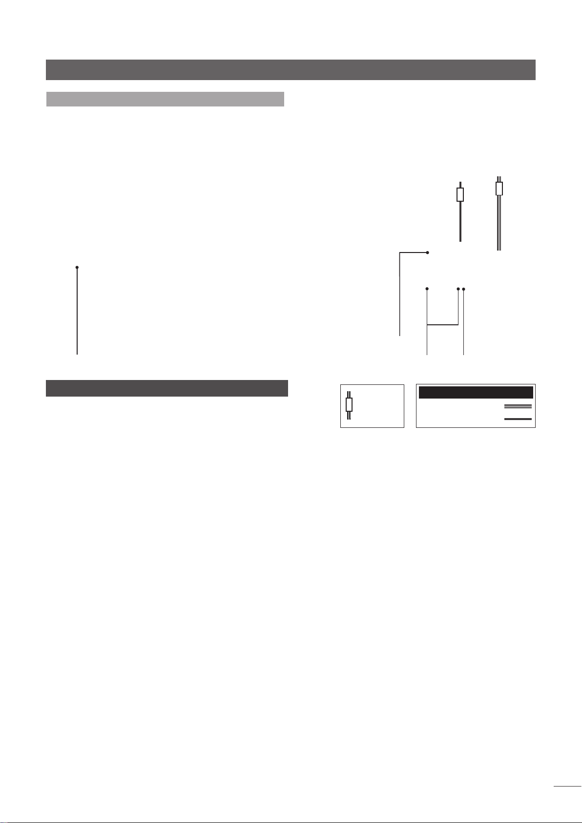
Vorstufe NAC 552
5.3 Anschluss an Netzteil NAC 552PS
Hinweis: Zur Optimierung der Klangqualität sollten das Burndy-
und das DIN-Kabel möglichst nah beieinander geführt werden.
zusätzlicher Signalausgang
Netzanschluss und
Sicherung
6 NAC 552/NAC 552PS – Technische Daten
Eingangsempfindlichkeit: 75 mV, 47 kΩ
Überlastungsgrenze: 40 dB (alle Eingänge, gesamter
Frequenzbereich)
Ausgangspegel Hauptausg.:
Ausgangspegel Tape: 75 mV, 600 Ω
Gleichstromausgang: für Naim-Phono-Vorstufe
Abmessungen (H x B x T): 87 x 432 x 314 mm (beide Geräte)
Gewicht: NAC 552 – 12,9 kg
NAC 552PS – 13,9 kg
Netzversorgung (NAC 552PS):
0,775 V, <50 Ω
100 V, 115 V oder 230 V; 50/60 Hz
Ausgänge für Mono-Endstufen oder
Doppel-Mono-Endstufe
Kabelrichtungsmarkierung
Ausgang für StereoEndstufe
Anschlusskabel
NAC-552-Burndy-Kabel
DIN-Kabel, 5-polig, 240°
D5

Vorstufe NAC 252
7 NAC 252 – Allgemeines und Installation
Die Vorstufe NAC 252 besitzt kein eigenes Netzteil und benötigt zur Stromversorgung das
Netzteil Supercap. Abbildung 8.3 zeigt, wie das Netzteil anzuschließen ist.
Bevor Sie Vorstufe und Netzteil anschließen und einschalten, sollten Sie beide Geräte auf
ein dafür vorgesehenes Rack stellen. Stellen Sie keines der beiden Geräte direkt auf ein
anderes und achten Sie darauf, dass die Vorstufe waagrecht steht. Vor dem Einschalten
sollten Sie sicherstellen, dass die Endstufen ausgeschaltet sind und der Lautstärkeregler
heruntergedreht ist. Der Netzschalter befindet sich an der Vorderseite des Netzteils.
Das Netzteil ist sehr schwer – bitte bedenken Sie dies, wenn Sie das Gerät hochheben
oder umstellen wollen. Stellen Sie sicher, dass die Unterlage für das Gewicht geeignet ist.
In den folgenden Abschnitten werden spezifische Merkmale und Funktionen der NAC 252
beschrieben. Informationen zur Bedienung aller Vorstufen und Vollverstärker finden Sie in
Abschnitt 28.
7.1 Eingänge und Record-Ausgänge
Mit den Eingangswahltasten in der oberen Tastenreihe
können Sie festlegen, welches Quellsignal zur Endstufe
und zu den Lautsprechern geleitet wird. Mit den RecordWahltasten in der unteren Tastenreihe können Sie festlegen,
welches Quellsignal an die Record-Ausgänge der Vorstufe
geleitet wird.
Getrennte Eingangswahl- und Record-Wahltasten
ermöglichen es, eine Quelle (z.B. einen CD-Spieler) zum
Anhören auszuwählen, während eine andere (z.B. ein Tuner)
zum Aufnehmen ausgewählt ist.
Hinweis: Die Record-Tasten können gesperrt werden, um
ein versehentliches Umschalten während des Aufnehmens
zu verhindern. Um die Tasten zu sperren bzw. zu entsperren,
betätigen Sie die Eingangstaste mono viermal innerhalb von
sechs Sekunden.
7.2 Eingänge konfigurieren
An der Rückseite der NAC 252 befinden sich sechs
DIN-Eingänge und zwei Cinchbuchsenpaare. Jeder
Eingangswahltaste ist werkseitig ein DIN-Eingang
zugewiesen, den Tasten cd und aux 2 kann jedoch
anstelle des jeweiligen DIN-Eingangs das entsprechende
Cinchbuchsenpaar zugewiesen werden.
Zum Neukonfigurieren der Eingänge cd und aux 2 muss der
Programmiermodus gestartet werden. Halten Sie dazu die
Fernbedienungstaste prog gedrückt (Fernbedienungsmodus
pre). Der Programmiermodus wird dadurch angezeigt, dass
die LED-Anzeige des Lautstärkereglers blinkt und die RecordTasten erlöschen.
Hinweis: Wenn Sie fünf Minuten lang keine Taste betätigen,
kehrt die Vorstufe wieder in den normalen Betriebsmodus
zurück.
Um der Eingangswahltaste cd das entsprechende
Cinchbuchsenpaar zuzuweisen, halten Sie Zifferntaste 1 der
Fernbedienung gedrückt, und um der Eingangswahltaste
aux 2 das entsprechende Cinchbuchsenpaar zuzuweisen,
Zifferntaste 6. Anstelle der Zifferntasten können Sie
auch die entsprechenden Eingangswahltasten an der
Gerätefront verwenden. Wiederholen Sie den Vorgang
jeweils, um der Taste wieder den DIN-Eingang zuzuweisen.
Wenn das Cinchbuchsenpaar ausgewählt wird, blinkt die
entsprechende Eingangswahltaste dreimal; wenn der DINEingang ausgewählt wird, blinkt sie einmal.
Um den Programmiermodus zu beenden, halten Sie die
Fernbedienungstaste prog gedrückt, bis die LED-Anzeige des
Lautstärkereglers aufhört zu blinken und die Record-Tasten
wieder leuchten.
Informationen zur
Bedienung aller
Vorstufen und
Vollverstärker finden
Sie in Abschnitt 28.
D6
8 NAC 252 – Bedienelemente und Anschlüsse
8.1 Gerätefront
Lautstärke
Balance
Eingangs-
Tasten
Record-
Tasten
Mono
Stummschaltung
Eingangswahl- und
Record-Wahltasten

Vorstufe NAC 252
Eing. 5
8.2 Rückseite
aux 1
Eing. 6
aux 2
Supercap RC5-
Supercap
Eingang
Eing. 1 cdEing. 2
Eingang 1, 2 + 6
Knl1
Knl2
-ve
tuner
nc
nc
Eing. 4
Eing. 3
av
tape
Eingang 3, 4 + 5
Knl1
Knl2
-ve
Eing. 6 (Alternativbuchse)
Masseanschluss
Eingang 6
Knl1
Ausg
Knl2
Ausg
(Alternativbuchse)
+ve
Knl2
8.3 Anschluss an Netzteil Supercap
Hinweis: Zur Optimierung der Klangqualität sollten das Burndy- und
das DIN-Kabel möglichst nah beieinander geführt werden.
-ve
+ve
Knl1
Cinchbuchsen cd
Knl 1 (L)
Knl 2 (R)
Hinweis: Eingang aux 2 ist mit zwei DIN-Buchsen ausgestattet.
Die untere Buchse (werkseitig mit einer Blindkappe
versehen) ist für den direkten Anschluss einer Naim-PhonoVorstufe ausgelegt und mit einem entsprechenden
Gleichstromausgang ausgestattet. Die beiden Buchsen
sollten nicht gleichzeitig verwendet werden.
Hinweis: Die RS232-/Kommunikationsschnittstelle ist ein
optionales Upgrade. Sie kann ab Werk bestellt oder
nachgerüstet werden. Weitere Informationen hierzu erhalten
Sie von Ihrem Händler, der zuständigen Vertriebsgesellschaft
oder Naim Audio.
Cinchbuchsen aux 2
Knl 1 (L)
Knl 2 (R)
RS232-Schnittstelle
Netzanschluss und
Sicherung
9 NAC 252/Supercap – Technische Daten
Eingangsempfindlichkeit: 75 mV, 47 kΩ
Überlastungsgrenze: 40 dB (alle Eingänge, gesamter
Frequenzbereich)
Ausgangspegel Hauptausg.:
Ausgangspegel Tape: 75 mV, 600 Ω
Gleichstromausgang: für Naim-Phono-Vorstufe
Abmessungen (H x B x T): 87 x 432 x 314 mm (beide Geräte)
Gewicht: NAC 252 – 7,0 kg
Supercap – 11,6 kg
Netzversorgung (Supercap):
0,775 V, <50 Ω
100 V, 115 V oder 230 V; 50/60 Hz
zusätzlicher Signalausgang
Ausgänge für Mono-Endstufen
oder Doppel-Mono-Endstufe
Kabelrichtungsmarkierung
Ausgang für
Stereo-Endstufe
Anschlusskabel
NAC-252-Burndy-Kabel
DIN-Kabel, 5-polig, 240°
D7

Vorstufe NAC 282
10 NAC 282 – Allgemeines und Installation
Die Vorstufe NAC 282 besitzt kein eigenes Netzteil und muss zur Stromversorgung an
eine Naim-Endstufe mit entsprechendem Gleichstromausgang oder an ein geeignetes
separates Naim-Netzteil angeschlossen werden. Das im Lieferumfang enthaltene Netzteil
des Typs NAPSC ist nur für die Versorgung der Tastenbeleuchtung und des Schaltnetzwerks
der Vorstufe zuständig. Abbildungen 11.3 und 11.4 zeigen, wie das Netzteil Supercap bzw.
Hi-Cap anzuschließen ist.
Bevor Sie Vorstufe und Netzteil(e) anschließen und einschalten, sollten Sie die Geräte auf
ein dafür vorgesehenes Rack stellen. Stellen Sie keines der Geräte direkt auf ein anderes
und achten Sie darauf, dass die Vorstufe waagrecht steht. Vor dem Einschalten sollten Sie
sicherstellen, dass der Lautstärkeregler heruntergedreht ist.
In den folgenden Abschnitten werden spezifische Merkmale und Funktionen der NAC 282
beschrieben. Informationen zur Bedienung aller Vorstufen und Vollverstärker finden Sie in
Abschnitt 28.
Informationen zur
Bedienung aller
Vorstufen und
Vollverstärker finden
Sie in Abschnitt 28.
10.1 Eingänge und Record-Ausgänge
Mit den Eingangswahltasten in der oberen Tastenreihe
können Sie festlegen, welches Quellsignal zur Endstufe
und zu den Lautsprechern geleitet wird. Mit den RecordWahltasten in der unteren Tastenreihe können Sie festlegen,
welches Quellsignal an die Record-Ausgänge der Vorstufe
geleitet wird.
Getrennte Eingangswahl- und Record-Wahltasten
ermöglichen es, eine Quelle (z.B. einen CD-Spieler) zum
Anhören auszuwählen, während eine andere (z.B. ein Tuner)
zum Aufnehmen ausgewählt ist.
Hinweis: Die Record-Tasten können gesperrt werden, um
ein versehentliches Umschalten während des Aufnehmens
zu verhindern. Um die Tasten zu sperren bzw. zu entsperren,
betätigen Sie die Eingangstaste mono viermal innerhalb von
sechs Sekunden.
10.2 Eingänge konfigurieren
An der Rückseite der NAC 282 befinden sich sechs
DIN-Eingänge und zwei Cinchbuchsenpaare. Jeder
Eingangswahltaste ist werkseitig ein DIN-Eingang
zugewiesen, den Tasten cd und aux 2 kann jedoch
11 NAC 282 – Bedienelemente und Anschlüsse
11.1 Gerätefront
anstelle des jeweiligen DIN-Eingangs das entsprechende
Cinchbuchsenpaar zugewiesen werden.
Zum Neukonfigurieren der Eingänge cd und aux 2 muss der
Programmiermodus gestartet werden. Halten Sie dazu die
Fernbedienungstaste prog gedrückt (Fernbedienungsmodus
pre). Der Programmiermodus wird dadurch angezeigt, dass
die LED-Anzeige des Lautstärkereglers blinkt und die RecordTasten erlöschen.
Hinweis: Wenn Sie fünf Minuten lang keine Taste betätigen,
kehrt die Vorstufe wieder in den normalen Betriebsmodus
zurück.
Um der Eingangswahltaste cd das entsprechende
Cinchbuchsenpaar zuzuweisen, halten Sie Zifferntaste 1 der
Fernbedienung gedrückt, und um der Eingangswahltaste
aux 2 das entsprechende Cinchbuchsenpaar zuzuweisen,
Zifferntaste 6. Anstelle der Zifferntasten können Sie
auch die entsprechenden Eingangswahltasten an der
Gerätefront verwenden. Wiederholen Sie den Vorgang
jeweils, um der Taste wieder den DIN-Eingang zuzuweisen.
Wenn das Cinchbuchsenpaar ausgewählt wird, blinkt die
entsprechende Eingangswahltaste dreimal, wenn der DINEingang ausgewählt wird, blinkt sie einmal.
Um den Programmiermodus zu beenden, halten Sie die
Fernbedienungstaste prog gedrückt, bis die LED-Anzeige des
Lautstärkereglers aufhört zu blinken und die Record-Tasten
wieder leuchten.
D8
Lautstärke
Balance
Eingangs-
Tasten
Record-
Tasten
Mono
Stummschaltung
Eingangswahl- und
Record-Wahltasten

Vorstufe NAC 282
11.2 Rückseite
Eing. 1 cdEing. 2
tuner
Eingang 1, 2 + 6
-ve
nc
nc
Knl1
Knl2
Eing. 4
Eing. 3
av
tape
Eingang 3, 4 + 5
Knl1
Knl2
-ve
Eing. 5
Eing. 6
aux 1
aux 2
Eing. 6 (Alternativbuchse) Cinchbuchsen
Masseanschluss
Eingang 6
Knl1
Ausg
Knl2
Ausg
(Alternativbuchse)
+ve
Knl2
Eingänge für optionales Netzteil (Brück-
enstecker und Blindkappe gesteckt)
+ve
Knl1
-ve
NAPSC
cd
Knl 1 (L)
Knl 2 (R)
Hinweis: Eingang aux 2 ist mit zwei DIN-Buchsen ausgestattet.
Die untere Buchse (werkseitig mit einer Blindkappe
versehen) ist für den direkten Anschluss einer Naim-PhonoVorstufe ausgelegt und mit einem entsprechenden
Gleichstromausgang ausgestattet. Die beiden Buchsen
sollten nicht gleichzeitig verwendet werden.
Hinweis: Die RS232-/Kommunikationsschnittstelle ist ein
optionales Upgrade. Sie kann ab Werk bestellt oder
nachgerüstet werden. Weitere Informationen hierzu erhalten
Sie von Ihrem Händler, der zuständigen Vertriebsgesellschaft
oder Naim Audio.
Cinchbuchsen
aux 2
Knl 1 (L)
Knl 2 (R)
Endstufe
mit Gleichstromausgang
RC5Eingang
RS232Schnittstelle
11.3 Anschluss an die Netzteile Supercap und NAPSC
zusätzlicher Signalausgang
Netzanschluss und
Sicherung
Kabelrichtungsmarkierung
Anschlusskabel
DIN-Kabel, 4-polig
DIN-Kabel, 5-polig, 240°
Ausgänge für Mono-Endstufen
oder Doppel-Mono-Endstufe
Ausgang für
Stereo-Endstufe
D9

Vorstufe NAC 282
11.4 Anschluss an die Netzteile Hi-Cap und NAPSC
Ausgang für Stereo-Endstufe
Netzanschluss und
Sicherung
Hinweis: Informationen zu weiteren Produktkombinationen
und Upgrades erhalten Sie von Ihrem Händler, der
zuständigen Vertriebsgesellschaft oder Naim Audio.
zusätzlicher
Signalausgang
Ausgänge für Mono-Endstufen oder Doppel-MonoEndstufe
12 NAC 282 – Technische Daten
Eingangsempfindlichkeit: 75 mV, 47 kΩ
Überlastungsgrenze: 40 dB (alle Eingänge, gesamter
Frequenzbereich)
Ausgangspegel Hauptausg.:
Ausgangspegel Tape: 75 mV, 600 Ω
Gleichstromausgang: für Naim-Phono-Vorstufe
Abmessungen (H x B x T): 87 x 432 x 314 mm (beide Geräte)
Gewicht: 7,0 kg
Netzversorgung (Hi-Cap):
0,775 V, <50 Ω
100 V, 115 V oder 230 V; 50/60 Hz
Kabelrichtungsmarkierung
Anschlusskabel
DIN-Kabel, 5-polig, 240°
D10

Vorstufe NAC 202
13 NAC 202 – Allgemeines und Installation
Die Vorstufe NAC 202 besitzt kein eigenes Netzteil und muss zur Stromversorgung an
eine Naim-Endstufe mit entsprechendem Gleichstromausgang oder an ein geeignetes
separates Naim-Netzteil angeschlossen werden. Optional erhältlich ist außerdem
das Netzteil NAPSC, das nur für die Versorgung der Tastenbeleuchtung und des
Schaltnetzwerks der Vorstufe zuständig ist. Abbildung 14.3 zeigt, wie die Netzteile Hi-Cap
und NAPSC anzuschließen sind.
Bevor Sie die Vorstufe und gegebenenfalls vorhandene Netzteile anschließen und
einschalten, sollten Sie die Geräte auf ein dafür vorgesehenes Rack stellen. Stellen
Sie keines der Geräte direkt auf ein anderes und achten Sie darauf, dass die Vorstufe
waagrecht steht. Vor dem Einschalten sollten Sie sicherstellen, dass der Lautstärkeregler
heruntergedreht ist.
In den folgenden Abschnitten werden spezifische Merkmale und Funktionen der NAC 202
beschrieben. Informationen zur Bedienung aller Vorstufen und Vollverstärker finden Sie in
Abschnitt 28.
Informationen zur
Bedienung aller
Vorstufen und
Vollverstärker finden
Sie in Abschnitt 28.
13.1 Eingänge und Konfiguration
Mit den Eingangswahltasten können Sie festlegen, welches
Quellsignal zur Endstufe und zu den Lautsprechern geleitet
wird.
An der Rückseite der NAC 202 befinden sich sechs
DIN-Eingänge und zwei Cinchbuchsenpaare. Jeder
Eingangswahltaste ist werkseitig ein DIN-Eingang
zugewiesen, den Tasten cd und aux 2 kann jedoch
anstelle des jeweiligen DIN-Eingangs das entsprechende
Cinchbuchsenpaar zugewiesen werden.
Zum Neukonfigurieren der Eingänge cd und aux 2 muss der
Programmiermodus gestartet werden. Halten Sie dazu die
Fernbedienungstaste prog gedrückt (Fernbedienungsmodus
pre). Der Programmiermodus wird dadurch angezeigt, dass
die LED-Anzeige des Lautstärkereglers blinkt und die RecordTasten erlöschen.
Hinweis: Wenn Sie fünf Minuten lang keine Taste betätigen,
kehrt die Vorstufe wieder in den normalen Betriebsmodus
zurück.
14 NAC 202 – Bedienelemente und Anschlüsse
Um der Eingangswahltaste cd das entsprechende
Cinchbuchsenpaar zuzuweisen, halten Sie Zifferntaste 1 der
Fernbedienung gedrückt, und um der Eingangswahltaste
aux 2 das entsprechende Cinchbuchsenpaar zuzuweisen,
Zifferntaste 6. Anstelle der Zifferntasten können Sie
auch die entsprechenden Eingangswahltasten an der
Gerätefront verwenden. Wiederholen Sie den Vorgang
jeweils, um der Taste wieder den DIN-Eingang zuzuweisen.
Wenn das Cinchbuchsenpaar ausgewählt wird, blinkt die
entsprechende Eingangswahltaste dreimal, wenn der DINEingang ausgewählt wird, blinkt sie einmal.
13.2 Stummschalten der Record-Ausgänge
Zur Reduzierung des Stromverbrauchs und zur Verbesserung
der Klangqualität können die Record-Ausgänge der NAC
202 stummgeschaltet werden. Um die Stummschaltung
zu aktivieren bzw. zu deaktivieren, drücken Sie die
Bedienfeldtaste mon und dann die Bedienfeldtaste mute.
Wenn die Record-Ausgänge stummgeschaltet sind, leuchtet
die Taste mute. Die Stummschaltung lässt sich wahlweise
auch über die Fernbedienungstasten mon und mute
aktivieren.
14.1 Gerätefront
Lautstärke
Monitorfunktion
Stummschaltung
Eingangswahltasten
D11

Vorstufe NAC 202
14.2 Rückseite
Eing. 1 cdEing. 2
tuner
Eingang 1, 2 + 6
-ve
nc
nc
Knl1
Knl2
Masseanschluss
Eing. 4
Eing. 3
av
tape
Eingang 3, 4 + 5
Knl1
Knl2
-ve
Eing. 5
aux 1
Knl1
Ausg
Knl2
Ausg
Eing. 6
(Alternativbuchse)
Eing. 6
aux 2
Eingang 6
(Alternativbuchse)
+ve
Knl2
-ve
Eingänge für optionales Netzteil (Brück-
enstecker und Blindkappe gesteckt)
+ve
Knl1
Cinchbuchsen
Hinweis: Eingang aux 2 ist mit zwei DIN-Buchsen
ausgestattet. Die obere Buchse (werkseitig mit einer
Blindkappe versehen) ist für den direkten Anschluss
einer Naim-Phono-Vorstufe ausgelegt und mit einem
entsprechenden Gleichstromausgang ausgestattet. Die
beiden Buchsen sollten nicht gleichzeitig verwendet
werden.
Hinweis: Die RS232-/Kommunikationsschnittstelle ist
ein optionales Upgrade. Sie kann ab Werk bestellt
oder nachgerüstet werden. Weitere Informationen
hierzu erhalten Sie von Ihrem Händler, der zuständigen
Vertriebsgesellschaft oder Naim Audio.
cd
Knl 1 (L)
Knl 2 (R)
NAPSC
Cinchbuchsen aux 2
Knl 1 (L)
Knl 2 (R)
Endstufe
mit Gleichstromausgang
RC5Eingang
RS232Schnittstelle
14.3 Anschluss an die Netzteile Hi-Cap und NAPSC
Ausgang für Stereo-Endstufe
15 NAC 202 – Technische Daten
Eingangsempfindlichkeit: 75 mV, 47 kΩ
Netzanschluss und
Sicherung
Kabelrichtungsmarkierung
zusätzlicher
Signalausgang
Anschlusskabel
DIN-Kabel, 4-polig
DIN-Kabel, 5-polig, 240°
Ausgänge für
Mono-Endstufen
oder DoppelMono-Endstufe
Überlastungsgrenze: 40 dB (alle Eingänge, gesamter
Frequenzbereich)
Ausgangspegel Hauptausg.:
Ausgangspegel Tape: 75 mV, 600 Ω
Gleichstromausgang: für Naim-Phono-Vorstufe
Abmessungen (H x B x T): 87 x 432 x 314 mm
Gewicht: 7,0 kg
Netzversorgung (Hi-Cap):
0,775 V, <50 Ω
100 V, 115 V oder 230 V; 50/60 Hz
D12

Vorstufe NAC 152 XS
16 NAC 152 XS – Allgemeines und Installation
Die Vorstufe NAC 152 XS besitzt kein eigenes Netzteil und muss zur Stromversorgung an
eine Naim-Endstufe mit entsprechendem Gleichstromausgang oder an ein geeignetes
separates Naim-Netzteil angeschlossen werden. Abbildung 17.3 zeigt, wie das Netzteil
Flatcapx anzuschließen ist.
Bevor Sie die Vorstufe und ein gegebenenfalls vorhandenes Netzteil anschließen und
einschalten, sollten Sie die Geräte auf ein dafür vorgesehenes Rack stellen. Stellen
Sie keines der Geräte direkt auf ein anderes und achten Sie darauf, dass die Vorstufe
waagrecht steht. Vor dem Einschalten sollten Sie sicherstellen, dass der Lautstärkeregler
heruntergedreht ist.
In den folgenden Abschnitten werden spezifische Merkmale und Funktionen der NAC 152
XS beschrieben. Informationen zur Bedienung aller Vorstufen und Vollverstärker finden Sie
in Abschnitt 28.
Informationen zur
Bedienung aller
Vorstufen und
Vollverstärker finden
Sie in Abschnitt 28.
16.1 Audio-Eingänge
Mit den Eingangswahltasten können Sie festlegen, welches
Quellsignal zu den Vorstufenausgängen und zur Endstufe
geleitet wird.
An der Rückseite der NAC 152 XS befinden sich sechs DINBuchsen und fünf Cinchbuchsenpaare zum Anschließen
von Quellgeräten. Die Cinchbuchsen und die jeweils
dazugehörige DIN-Buchse eines Eingangs sind parallel
geschaltet und sollten nicht gleichzeitig verwendet werden.
Hinweis: Die DIN-Buchse aux 2 ist für den direkten Anschluss
einer Naim-Phono-Vorstufe ausgelegt und mit einem
entsprechenden Gleichstromausgang ausgestattet.
An der Vorderseite der NAC 152 XS steht zusätzlich eine
3,5-mm-Minibuchse zum Anschließen eines iPod (oder
ähnlicher Geräte) zur Verfügung. Diese Buchse ist mit der
DIN-Buchse und dem Cinchbuchsenpaar des Eingangs aux
1 parallel geschaltet.
Wird ein Stecker in die Minibuchse an der Gerätefront
gesteckt, schaltet der Verstärker automatisch auf diesen
Eingang. Wird der Stecker aus der Minibuchse gezogen,
schaltet der Verstärker auf den zuletzt ausgewählten
Eingang. Wenn ein anderer Eingang ausgewählt wird,
während ein Stecker in der Minibuchse steckt, bewirkt
ein späteres Ziehen des Steckers kein automatisches
Umschalten.
16.2 Audio-Ausgänge
Die NAC 152 XS besitzt einen Ausgang zum Anschließen
eines Subwoofers und einen Line-Ausgang; beide Ausgänge
sind als Cinchbuchsenpaar ausgelegt.
Hinweis: Der Subwoofer-Ausgang führt dasselbe Signal wie
der Hauptvorstufenausgang (d.h., ein angeschlossener
Subwoofer reagiert auf Änderungen der Lautstärke).
16.3 Erweiterung mit externem Netzteil
Die NAC 152 XS kann zur Verbesserung der Klangqualität
mit einem oder mehreren externen Netzteilen aufgerüstet
werden. Diese Erweiterung kann stufenweise erfolgen.
Stufe 1: Anschluss eines Netzteils des Typs i-Supply, Flatcap,
Hi-Cap oder Supercap an die Buchse upgrade 1. Hierzu
muss der in Buchse link 1 steckende Brückenstecker entfernt
werden.
Stufe 2: Anschluss eines Netzteils des Typs Flatcap, Hi-Cap
oder Supercap an die Buchse upgrade 2. Hierzu muss der in
dieser Buchse steckende Brückenstecker entfernt werden.
Ist ein zweites Netzteil an die NAC 152 XS angeschlossen,
benötigt diese keinen Strom von der Endstufe mehr;
die Endstufe sollte dann direkt an das zweite Netzteil
angeschlossen werden.
Abschnitt 17 enthält Anschlussdiagramme zu beiden
Erweiterungsstufen.
Hinweis: Brückenstecker sollten nur in die jeweils
dafür vorgesehenen Buchsen gesteckt werden,
und Netzteilbuchsen sollte nur für die vorgesehenen
Netzteilerweiterungen verwendet werden. Falsche
Verwendung von Brückensteckern und Netzteilbuchsen
kann das Netzteil oder die Vorstufe beschädigen.
Hinweis: Die Erweiterung der NAC 152 XS mit Netzteilen
lässt sich mit einer Reihe unterschiedlicher Konfigurationen
realisieren (u.a. auch durch die Verwendung eines Flatcap
für beide Erweiterungsstufen). Ihr Händler kann Ihnen helfen,
die für Ihre Anlage beste Konfiguration auszuwählen.
Hinweis: Das Netzteil NAPSC kann nicht mit der NAC 152 XS
verwendet werden.
D13

Vorstufe NAC 152 XS
17 NAC 152 XS – Bedienelemente und
Anschlüsse
17.1 Gerätefront
Lautstärke
17.2 Rückseite
Eing. cd
Eing. tun
(cinch)
Eing. cdEing.
Eingang cd, tun,
hdd, av und aux
Knl1
Knl2
Hinweis: Bei der NAC 152 XS wurden mehrere Verfahren
zur Reduzierung von Mikrofonie eingesetzt; geringfügige
Bewegungen der Buchsen beim Stecken und Ziehen von
Steckern sind konstruktionsbedingt.
(cinch)
tuner
-ve
Eing. hdd
(cinch)
Eing.
hdd
nc
nc
+ve
Knl2
Eing. A V
Eing.
Eingang aux 2
(Alternativbuchse)
(cinch)
av
Eing.
aux 1
Eing. aux
1 (cinch)
Eing.
aux 2
+ve
Knl1
-ve
Masseanschluss
Eing. aux 2 und
Ausg. Gleichspannung
Fronteingang
Endstufe mit Gleichstromausgang
Eingang für optionales Netzteil
(Brückenstecker gesteckt)
Hinweis: Eingang aux 2 ist mit zwei DIN-Buchsen
ausgestattet. Die rechte Buchse (werkseitig mit einer
Blindkappe versehen) ist für den direkten Anschluss
einer Naim-Phono-Vorstufe ausgelegt und mit einem
entsprechenden Gleichstromausgang ausgestattet. Die
beiden Buchsen sollten nicht gleichzeitig verwendet
werden.
Hinweis: Die RS232-/Kommunikationsschnittstelle ist
ein optionales Upgrade. Sie kann ab Werk bestellt
oder nachgerüstet werden. Weitere Informationen
hierzu erhalten Sie von Ihrem Händler, der zuständigen
Vertriebsgesellschaft oder Naim Audio.
Stummschaltung Eingangswahltasten
line
Ausgang
SubwooferAusgang
RC5 Eingang
RS232Schnittstelle
D14 D15

Vorstufe NAC 152 XS
17.3 Anschluss an Netzteil FlatCap XS (Erweiterungsstufe 1)
Endstufe mit Gleich-
strom-ausgang
Netzschalter
Netzanschluss und
Sicherung
Erweiterungsstufe 2, CD5XS,
Headline oder Phono-V orstufe
(es werden zusätzliche An-
schlusskabel benötigt)
Kabelrichtungsmarkierung
Anschlusskabel
DIN-Kabel, 4-polig
DIN-Kabel, 5-polig, 240°
D15

Vorstufe NAC 152 XS
17.4 Anschluss an die Netzteile Hi-Cap und FlatCap XS (Erweiterungsstufe 2)
Ausgang für Stereo-Endstufe
Netzanschluss und
Sicherung
Netzanschluss und
Netzschalter
Sicherung
zusätzlicher
Signalausgang
Ausgänge für
Mono-Endstufen
oder DoppelMono-Endstufe
Phono-V orstufe (es werden
zusätzliche Anschlusskabel
CD5 XS, Headline oder
benötigt)
Kabelrichtungsmarkierung
Anschlusskabel
DIN-Kabel, 4-polig
DIN-Kabel, 5-polig, 240°
D16
18 NAC 152 XS – Technische Daten
Eingangsempfindlichkeit: 130 mV, 47 kΩ
Überlastungsgrenze: 35 dB (alle Eingänge, gesamter
Frequenzbereich)
Ausgangspegel Hauptausg.:
Ausgangspegel Tape: 130 mV, 600 Ω
Gleichstromausgang: für Naim-Phono-Vorstufe
Abmessungen (H x B x T): 70 x 432 x 301 mm
Gewicht: 3,9 kg
Netzversorgung (FlatCap XS):
0,775 V, <50 Ω
100 V, 115 V oder 230 V; 50/60 Hz

Vollverstärker SUPERNAIT
19 SUPERNAIT – Allgemeines und Installation
Bevor Sie den Vollverstärker Supernait anschließen und einschalten, sollten Sie ihn auf ein
dafür vorgesehenes Rack stellen. Stellen Sie den Verstärker nicht direkt auf ein anderes
Gerät und achten Sie darauf, dass er waagrecht steht. Vor dem Einschalten sollten Sie
sicherstellen, dass der Lautstärkeregler heruntergedreht ist.
Es bestehen mehrere Möglichkeiten, den Supernait mit einem externen Netzteil, einer
anderen Vorstufe oder einer anderen oder zusätzlichen Endstufe aufzurüsten. Einige dieser
Möglichkeiten werden in den Abbildungen in Abschnitt 20 dargestellt.
In den folgenden Abschnitten werden spezifische Merkmale und Funktionen des Supernait
beschrieben. Informationen zur Bedienung aller Vorstufen und Vollverstärker finden Sie in
Abschnitt 28.
Informationen zur
Bedienung aller
Vorstufen und
Vollverstärker finden
Sie in Abschnitt 28.
19.1 Eingänge und Konfiguration
Mit den Eingangswahltasten cd, tuner, tape, av, aux 1
und aux 2 in der oberen Tastenreihe können Sie festlegen,
welches Quellsignal zu den Lautsprechern geleitet wird.
Jeder Eingangswahltaste können bestimmte
Analogeingänge (DIN-Buchsen, Cinchbuchsen und
3,5-mm-Minibuchse) oder jeder beliebige Digitaleingang
(Cinchbuchsen, TosLink-Buchsen und Mini-TosLink-Buchse)
zugewiesen werden. Die Werkseinstellungen und Hinweise
zum Neukonfigurieren der Eingänge können Sie Abschnitt
19.2 bzw. 19.3 entnehmen.
19.1.1 Analogeingänge
Jeder der ersten vier Eingangswahltasten (cd, tuner, tape
und av) können eine DIN-Buchse und ein zugehöriges
Cinchbuchsenpaar an der Geräterückseite zugewiesen
werden. Die DIN-Buchsen und das zugehörige
Cinchbuchsenpaar sind parallel geschaltet und sollten nicht
gleichzeitig verwendet werden.
Der Eingangswahltaste aux 1 kann ein Cinchbuchsenpaar
zugewiesen werden, der Eingangswahltaste aux 2 eine DINBuchse.
Hinweis: Die DIN-Buchse aux 2 ist für den direkten Anschluss
einer Naim-Phono-Vorstufe ausgelegt und mit einem
entsprechenden Gleichstromausgang ausgestattet.
19.1.2 Digitaleingänge
An der Rückseite des Supernait stehen zusätzlich zu den
Analogeingängen vier S/PDIF-Digitaleingänge zur Verfügung
(zwei Cinchbuchsen und zwei TosLink-Buchsen). Jeder
Digitaleingang kann jeder beliebigen Eingangswahltaste
zugewiesen werden.
Hinweis: Die Digitaleingänge unterstützen nur das Audio-
Format PCM Stereo. Gibt eine angeschlossene Signalquelle
ein anderes Format aus (z.B. Dolby oder DTS), werden alle
Ausgänge stummgeschaltet.
19.1.3 Kombi-Eingang an der Gerätefront
An der Vorderseite des Supernait steht zusätzlich ein KombiEingang zur Verfügung, die wahlweise als Analogeingang
(3,5-mm-Minibuchse) oder als Digitaleingang (MiniTosLink-Buchse) fungiert. Der Analogeingang und das
Cinchbuchsenpaar aux 1 an der Geräterückseite sind
parallel geschaltet und sollten nicht gleichzeitig verwendet
werden.
Wird ein Stecker in den Kombi-Eingang gesteckt, schaltet
der Supernait automatisch auf diesen Eingang (und weist
ihn der Eingangswahltaste aux 1 zu).
Hinweis: Der Supernait erkennt am Kombi-Eingang
angeschlossene Digitalquellen automatisch, sofern sie beim
Stecken bereits Programmmaterial abspielen.
Wird der Stecker aus dem Kombi-Eingang gezogen, schaltet
der Supernait automatisch auf den zuletzt ausgewählten
Eingang zurück.
19.2 Konfiguration der Eingänge – Werkseinstellungen
Eingangswahltaste Eingang (Buchse) Buchsentyp
cd Analogeingang 1 DIN und Cinch
tuner
Analogeingang 2 DIN und Cinch
tape
Digitaleingang 1 Cinch
av
Analogeingang 4 DIN und Cinch
aux 1
Digitaleingang 2 TosLink (optisch)
(siehe Hinweis)
aux 2
Analogeingang 6 DIN (mit Gleichstromausgang für Naim-
Phono-Vorstufe)
Hinweis: Wird ein Stecker in den Kombi-Eingang an der Gerätefront gesteckt, schaltet der
Supernait automatisch auf diesen Eingang und weist ihn der Eingangswahltaste aux 1 zu.
D17

Vollverstärker SUPERNAIT
19.3 Eingänge konfigurieren
Die in Tabelle 19.2 dargestellte Konfiguration der Eingänge
kann nur durch Neukonfigurieren der Digitaleingänge
geändert werden. Jeder Digitaleingang kann jeder
beliebigen Eingangswahltaste zugewiesen werden.
Zum Neukonfigurieren der Digitaleingänge muss
der Programmiermodus gestartet werden. Halten
Sie dazu die Fernbedienungstaste prog gedrückt
(Fernbedienungsmodus pre; wiederholen Sie den Vorgang,
wenn Sie den Programmiermodus beenden wollen). Der
Programmiermodus wird dadurch angezeigt, dass die LEDAnzeige des Lautstärkereglers blinkt.
Hinweis: Wenn Sie fünf Minuten lang keine Taste betätigen,
kehrt der Verstärker wieder in den normalen Betriebsmodus
zurück.
Um einer Eingangswahltaste einen Digitaleingang
zuzuweisen, drücken Sie zuerst die Eingangswahltaste und
dann eine Record-Wahltaste. Welche Record-Wahltaste
welchem Digitaleingang entspricht, können Sie der
nachstehenden Tabelle entnehmen.
Record-Wahltaste Digitaleingang
cd (entspricht) 1 (Cinch)
tuner (entspricht) 2 (optisch)
tape (entspricht) 3 (Cinch)
av (entspricht) 4 (optisch)
Um beispielsweise der Eingangswahltaste tuner den
Digitaleingang 4 zuzuweisen, gehen Sie folgt vor:
i. Starten Sie den Programmiermodus.
ii. Drücken Sie die Eingangswahltaste tuner.
iii. Drücken Sie die Record-Wahltaste av (die Taste leuchtet
daraufhin).
iv. Beenden Sie den Programmiermodus.
Durch Wiederholen dieses Vorgangs kann einer
Eingangswahltaste wieder der entsprechende
Analogeingang zugewiesen werden.
Um beispielsweise der Eingangswahltaste tuner den entsprechenden Analogeingang zuzuweisen, gehen Sie folgt vor:
i. Starten Sie den Programmiermodus.
ii. Drücken Sie die Eingangswahltaste tuner.
iii. Drücken Sie die (leuchtende) Record-Wahltaste av (die
Taste erlischt daraufhin).
iv. Beenden Sie den Programmiermodus.
19.4 Record-Ausgänge
Mit den Record-Wahltasten in der unteren Tastenreihe
können Sie festlegen, welches Quellsignal an den RecordAusgänge des Supernait geleitet wird.
Getrennte Eingangswahl- und Record-Wahltasten
ermöglichen es, eine Quelle (z.B. einen CD-Spieler) zum
Anhören auszuwählen, während eine andere (z.B. ein Tuner)
zum Aufnehmen ausgewählt ist.
Hinweis: Es ist nicht möglich, eine Digitalquelle zum Anhören
und eine andere zum Aufnehmen auszuwählen.
19.5 Lautsprecherausgänge
An der Geräterückseite befinden sich zwei Ausgänge
zum Anschließen von Stereo-Lautsprechern. Lassen Sie
Ihre Lautsprecherkabel nur mit den im Lieferumfang
des Verstärkers enthaltenen Naim-Audio-Steckern
konfektionieren; sie entsprechen den europäischen
Sicherheitsnormen. Wir empfehlen die Verwendung von
Naim-Lautsprecherkabeln, es können jedoch auch viele
andere Kabeltypen mit dem Supernait verwendet werden.
Achten Sie darauf, dass Sie die Lautsprecher richtig gepolt
anschließen, d.h., dass jeweils der Minuspol des Ausgangs
an den Minuspol des Lautsprechers und der Pluspol des
Ausgangs an den Pluspol des Lautsprechers angeschlossen ist.
19.6 Kopfhörerausgang
An der Gerätefront befindet sich eine 3,5-mm-Buchse zum
Anschließen eines Kopfhörers. Wird ein Kopfhörerstecker in
diese Buchse gesteckt, schaltet der Supernait automatisch
den integrierten Kopfhörerverstärker ein und – sofern
der Supernait entsprechend eingestellt ist – die
Lautsprecherausgänge stumm.
Um die automatische Stummschaltung der
Lautsprecherausgänge zu deaktivieren (bzw. wieder zu
aktivieren), starten Sie den Programmiermodus und drücken
Sie die Record-Wahltaste aux 2.
19.7 Zusätzliche Ein- und Ausgänge
An der Geräterückseite befindet sich ein Bi-AmpingAusgang (Vorstufenausgang) zum Anschließen einer
anderen oder (in Bi-Amping-Konfigurationen) zusätzlichen
Endstufe.
Hinweis: Zum Anschließen externer Endstufen sollte stets
dieser Ausgang verwendet werden.
Ferner stehen ein zweiter Vorstufenausgang und ein
Endstufeneingang zur Verfügung. Im normalen Betrieb
sind diese beiden Buchsen durch einen Brückenstecker
miteinander verbunden. Entfernen Sie den Brückenstecker
nur, wenn Sie ein externes Netzteil oder eine externe Vorstufe
anschließen wollen. Abbildungen 20.3 bis 20.5 zeigen, wie
diese Buchsen zu verwenden sind.
Wird eine externe Vorstufe an den Endstufeneingang des
Supernait angeschlossen, blinkt die Eingangstaste mute; dies
zeigt einen Fehlerzustand an. Halten Sie die blinkende Taste
gedrückt, um den Fehlerzustand zu beenden. Nun werden
die Lautsprecherausgänge der Endstufensektion wieder
aktiviert und die Tastenbeleuchtung wird ausgeschaltet.
Der Supernait besitzt einen Analogausgang zum Anschließen
eines Subwoofers; dieser Ausgang ist als Cinchbuchsenpaar
ausgelegt.
Hinweis: Der Subwoofer-Ausgang führt dasselbe Signal wie
der Vorstufenausgang. Es wird kein Tiefpassfilter eingesetzt.
19.8 Erweiterung mit externem Netzteil
Die Vorstufensektion des Supernait kann mit den externen
Netzteilen Flatcapx, Hi-Cap oder Supercap aufgerüstet
D18

Vollverstärker SUPERNAIT
werden. Die Abbildungen in Abschnitt 20 zeigen, wie
externe Netzteile anzuschließen sind. Der Supernait und das
externe Netzteil müssen ausgeschaltet sein, wenn Sie die
beiden Geräte miteinander verbinden. Schalten Sie danach
zuerst das Netzteil und dann den Supernait ein.
19.9 Allgemeine technische Hinweise
Die Minuspole des Eingangs und Ausgangs eines Kanals
sind miteinander verbunden. Unabhängig davon, welche
20 SUPERNAIT – Bedienelemente und Anschlüsse
20.1 Gerätefront
Lautstärke
Balance
anderen Geräte zusammen mit der Endstufe verwendet
werden, sollte der Schutzleiter stets angeschlossen sein. Er
erdet nur das Gehäuse und die Transformatorabschirmung
und ist nicht mit der Signalmasse verbunden. Zur
Vermeidung von Brummschleifen sollte die Signalmasse
der gesamten Anlage an einem einzigen Punkt mit dem
Schutzleiter verbunden sein.
Eingangswahl- und
Record-Wahltasten
Eingangs-Tasten
Record-Tasten
Stummschaltung
Kombi-Eingang
(analog/digital)
Kopfhörerausgang
20.2 Rückseite
Netz-
schalter
Eingang
cd und tuner
Knl1
Knl2
Bi-Amping-
Ausgang
Knl2
-ve
-ve
Netzanschluss und
Sicherung
nc
nc
Knl2
nc
RS232Schnittstelle
Eingang
tape und av
Knl1
Knl2
linker Lautsprecher
-ve
Knl1
Ausg
Knl2
Ausg
rechter Lautsprecher
Eingang aux 2
+ve
Knl2
-ve
RC5-Eing./
Masseanschluss
+ve
Knl1
Analog-
tape
Eing./
Ausg.
eingänge
Cinchbuchsen
tunertapeavaux1tapesubbi-amp1 2 3 4
cd
tuner
Eing.cdEing.
Ausg.
Endstufeneingang
und V orstufenaus-
gang (Brücken-
stecker gesteckt)
Digitaleingänge
Ausgänge
av
Eing./
Ausg.
aux 2
Eing. und Gleichstromausg.
Hinweis: Die RS232-/Kommunikationsschnittstelle ist ein
optionales Upgrade. Sie kann ab Werk bestellt oder
nachgerüstet werden. Weitere Informationen hierzu erhalten
Sie von Ihrem Händler, der zuständigen Vertriebsgesellschaft
oder Naim Audio.
Hinweis: Entfernen Sie den Brückenstecker nur, wenn Sie ein
externes Netzteil oder eine externe Vorstufe anschließen
wollen. Im normalen Betrieb müssen die beiden Buchsen
im Anschlussfeld „Upgrades“ mit dem Brückenstecker
verbunden sein.
D19

Vollverstärker SUPERNAIT
20.3 Anschluss an Netzteil Hi-Cap
Netz-
schal-
ter
Netzanschluss
und Sicherung
Netzanschluss
und Sicherung
20.4 Anschluss an Endstufe NAP 200
Kabelrichtungsmarkierung
Anschlusskabel
DIN-Kabel, 4-polig
DIN-Kabel, 5-polig, 240°
D20
Netz-
schal-
ter
Netzanschluss
und Sicherung
Netzanschluss
und Sicherung
Kabelrichtungsmarkierung
Anschlusskabel
DIN-Kabel, 4-polig

Vollverstärker SUPERNAIT
20.5 Anschluss an Netzteil Hi-Cap und Endstufe NAP 200
Netz-
schal-
ter
Netzanschluss
und Sicherung
Netzanschluss
und Sicherung
Kabelrichtungsmarkierung
Anschlusskabel
DIN-Kabel, 4-polig
DIN-Kabel, 5-polig, 240°
Netzanschluss
und Sicherung
21 SUPERNAIT – Technische Daten
Eingangsempfindlichkeit: 75 mV, 47 kΩ
Überlastungsgrenze: 40 dB (alle Eingänge, gesamter
Frequenzbereich)
Ausgangspegel Vorstufe: 0,775 V, <50 Ω
Ausgangspegel Tape: 75 mV, 600Ω
Ausgangsleistung: 80 Watt pro Kanal an 8 Ω,
Sinusleistung
Gleichstromausgang: für Naim-Phono-Vorstufe
Leistungsaufnahme:
Abmessungen (H x B x T): 87 x 432 x 314 mm
Gewicht: 12,8 kg
Netzversorgung : 100 V, 115 V oder 230 V; 50/60 Hz
10 VA im Ruhezustand
D21

Vollverstärker NAIT XS
22 NAIT XS – Allgemeines und Installation
Bevor Sie den NAIT XS anschließen und einschalten, sollten Sie ihn auf ein dafür
vorgesehenes Rack stellen. Stellen Sie den Verstärker nicht direkt auf ein anderes
Gerät und achten Sie darauf, dass er waagrecht steht. Vor dem Einschalten sollten Sie
sicherstellen, dass der Lautstärkeregler heruntergedreht ist.
Es bestehen mehrere Möglichkeiten, den NAIT XS mit einem externen Netzteil, einer
anderen Vorstufe oder einer anderen oder zusätzlichen Endstufe aufzurüsten. Einige
der Anschlussmöglichkeiten werden in den Abbildungen in Abschnitt 7 dargestellt.
Über weitere Anschlussmöglichkeiten informiert Sie Ihr Händler oder die zuständige
Vertriebsgesellschaft.
An der Rückseite des NAIT XS befindet sich ein Schalter („AV Bypass“) für
AV-Anwendungen. Stellen Sie diesen Schalter nur auf „On“, wenn Sie den Verstärker in
Kombination mit einem AV-Prozessor verwenden. Für alle anderen Betriebsarten sollte der
AV-Schalter auf „Off“ stehen. Sowohl der Verstärker als auch die Lautsprecher können
beschädigt werden, wenn ein Signal an den AV-Eingang des NAIT XS geleitet wird,
während der AV-Schalter auf „On“ steht.
Informationen zur Bedienung aller Vorstufen und Vollverstärker finden Sie in Abschnitt 28.
Informationen zur
Bedienung aller
Vorstufen und
Vollverstärker finden
Sie in Abschnitt 28.
22.1 Netzanschluss
Verwenden Sie das mitgelieferte Netzkabel oder ein
Naim Power-Line, um den NAIT XS an das Stromnetz
anzuschließen.
22.2 Signaleingänge
Mit den Eingangswahltasten cd, tuner, hdd, av, aux 1 und
aux 2 können Sie festlegen, welches Quellsignal zu den
Lautsprechern geleitet wird.
Die Eingänge cd, tuner, hdd und av sind jeweils als
Cinchbuchsenpaar und als parallel geschaltete DIN-Buchse
ausgelegt.
Hinweis: Die DIN-Buchsen hdd in/out und av in/out dienen
auch als Signalausgänge. Weitere Informationen hierzu
finden Sie in Abschnitt 22.4.
Eingang aux 1 ist als Cinchbuchsenpaar an der Rückseite
und als parallel geschaltete 3,5-mm-Minibuchse (Stereo)
an der Gerätefront ausgelegt. Wird ein Stecker in die
Minibuchse an der Gerätefront gesteckt, schaltet der
Verstärker automatisch auf Eingang aux 1. Wird der Stecker
aus der Minibuchse gezogen, schaltet der Verstärker auf
den zuletzt ausgewählten Eingang. Wenn ein anderer
Eingang ausgewählt wird, während ein Stecker in der
Minibuchse steckt, bewirkt ein späteres Ziehen des Steckers
kein automatisches Umschalten.
Eingang aux 2 ist als DIN-Buchse an der Rückseite
ausgelegt. Diese Buchse verfügt außerdem über einen
Gleichstromausgang zur Versorgung einer Naim-PhonoVorstufe des Typs Stageline oder SuperLine.
Hinweis: Wenn die Möglichkeit besteht, zwischen DIN- und
Cinchbuchsen zu wählen, sollten Sie die DIN-Buchsen
verwenden.
Hinweis: Bei Eingängen mit parallel geschalteten DIN- und
Cinchbuchsen sollte immer nur ein Buchsentyp verwendet
werden.
Verwenden Sie zum Anschließen von Quellgeräten
hochwertige Signalkabel. Wir empfehlen das Naim Hi-Line.
22.3 Lautsprecherausgänge
An der Geräterückseite befinden sich zwei Ausgänge
zum Anschließen von Stereo-Lautsprechern. Lassen Sie
Ihre Lautsprecherkabel nur mit den im Lieferumfang des
Verstärkers enthaltenen Naim-Steckern konfektionieren;
sie entsprechen den europäischen Sicherheitsnormen. Wir
empfehlen die Verwendung von Naim-Lautsprecherkabeln,
es können jedoch auch viele andere Kabeltypen mit dem
NAIT XS verwendet werden.
Achten Sie darauf, dass Sie die Lautsprecher richtig gepolt
anschließen, d.h., dass jeweils der Minuspol des Ausgangs
an den Minuspol des Lautsprechers und der Pluspol des
Ausgangs an den Pluspol des Lautsprechers angeschlossen
ist.
22.4 HDD- und AV-Eingänge und -Ausgänge
Die DIN-Buchsen hdd in/out und av in/out dienen auch
als Signalausgänge, was es ermöglicht, das ausgewählte
Quellsignal an ein externes Gerät, z.B. ein Aufnahmegerät,
weiterzuleiten.
Hinweis: Die Ausgänge der Buchsen hdd in/out und av
in/out werden automatisch stummgeschaltet, wenn der
dazugehörige Eingang ausgewählt wird.
22.5 AV-Modus
Der AV-Modus ermöglicht die Verwendung des NAIT XS zur
Verstärkung der beiden Hauptlautsprecherkanäle in einer
Mehrkanal-Heimkinoanlage. In einer solchen Konfiguration
übernimmt der AV-Prozessor die Lautstärkeregelung des
Quellsignals, das am Eingang av des NAIT XS anliegt. Der
AV-Modus lässt sich mithilfe des Schalters „AV Bypass“ an der
Geräterückseite aktivieren. Wenn der Modus aktiv ist und
D22

Vollverstärker NAIT XS
der Eingang av ausgewählt wird, erlischt die LED-Anzeige
des Lautstärkereglers und die Fernbedienungsfunktion für die
Lautstärke wird deaktiviert.
Hinweis: Bei der Verwendung des AV-Modus ist
Vorsicht geboten. Wenn der Modus aktiv ist, wird die
Lautstärkeregelung des NAIT XS umgangen, sodass ein am
Eingang av anliegendes Signal mit voller Lautstärke an die
Lautsprecher geleitet wird.
Hinweis: Wenn der AV-Modus aktiv ist, wird die
Stummschaltungsfunktion des NAIT XS deaktiviert.
22.6 Zusätzliche Ein- und Ausgänge
An der Geräterückseite befinden sich ein Vorstufenausgang
(pre-amp out) und ein Endstufeneingang (power amp in).
Im normalen Betrieb sind diese beiden Buchsen durch einen
Brückenstecker miteinander verbunden. Entfernen Sie den
Brückenstecker nur
• zum Anschließen eines externen Netzteils,
• zum Anschließen einer externen Vorstufe an die
Endstufensektion des NAIT XS oder
• zum Anschließen einer externen Endstufe an die
Vorstufensektion des NAIT XS.
Die Abbildungen 23.3 und 23.4 zeigen, wie die Buchsen zu
verwenden sind.
Wird eine externe Vorstufe an den Endstufeneingang des
NAIT XS angeschlossen, blinkt die Eingangstaste mute; dies
zeigt einen Fehlerzustand an. Halten Sie die blinkende Taste
gedrückt, um den Fehlerzustand zu beenden. Nun wird die
Endstufensektion wieder aktiviert; die Tastenbeleuchtung
und die LED-Anzeige des Lautstärkereglers werden
ausgeschaltet.
Der NAIT XS besitzt einen Analogausgang zum Anschließen
eines Subwoofers; dieser Ausgang ist als Cinchbuchsenpaar
ausgelegt.
Hinweis: Der Subwoofer-Ausgang führt dasselbe Signal wie
der Vorstufenausgang. Es wird kein Tiefpassfilter eingesetzt.
22.7 Erweiterung mit externem Netzteil
Die Vorstufensektion des NAIT XS kann mit einem externen
Netzteil des Typs Flatcapx, Hi-Cap oder Supercap
aufgerüstet werden. Die Abbildungen in Abschnitt 7 zeigen,
wie externe Netzteile anzuschließen sind. Der NAIT XS und
das externe Netzteil müssen ausgeschaltet sein, wenn Sie die
beiden Geräte miteinander verbinden. Schalten Sie danach
zuerst das Netzteil und dann den NAIT XS ein.
22.8 Allgemeine technische Hinweise
Die Minuspole des Eingangs und Ausgangs eines Kanals
sind miteinander verbunden. Unabhängig davon, welche
anderen Geräte zusammen mit dem NAIT XS verwendet
werden, sollte der Schutzleiter stets angeschlossen sein. Er
erdet nur das Gehäuse und die Transformatorabschirmung
und ist nicht mit der Signalmasse verbunden. Zur
Vermeidung von Brummschleifen sollte die Signalmasse
der gesamten Anlage an einem einzigen Punkt mit dem
Schutzleiter verbunden sein.
Der an der Geräterückseite befindliche Masseanschluss
sollte nur zum Anschließen der Signalmasse eines
Plattenspielertonarms verwendet werden.
23 NAIT XS – Bedienelemente und Anschlüsse
23.1 Gerätefront
Lautstärke
Eingangsbuchse aux 1
Eingangswahltasten
Stummschaltung
D23

Vollverstärker NAIT XS
23.2 Rückseite
Subwoofer-
RC5-Eing.
Ausg.
aux 1
Eing. avEing.
hdd
Eing.
tuner
Eing.cdEing.
Netz-
schalter
Netzan-
schluss
und
Sicherung
Eingang cd und
tuner
Knl 1
L
Knl 2
R
-ve
RS232-
Schnitt-
stelle
Eingang hdd und
Knl 1
nc
Knl 2
nc
linker
Laut-
sprecher
av
L
R
-ve
Lautspre-
Knl 1
(Ausg.)
Knl 2
(Ausg.)
rechter
cher
Masseanschluss
Eingang aux 2
+ve
Knl 2
R
Hinweis: Beim NAIT XS wurden mehrere Verfahren zur
Reduzierung von Mikrofonie eingesetzt; geringfügige
Bewegungen der Buchsen beim Stecken und Ziehen von
Steckern sind konstruktionsbedingt.
23.3 Anschluss an Netzteil FlatCap XS
-ve
+ve
Knl 1
L
av
hdd
AV-
Schalter
Endstufenein-
gang und V or-
stufenausgang
(Brückenste-
cker gesteckt)
aux 2
Eing.
und
Gleichstromausg.
Eing./
Ausg.
Eing./
Ausg.
tuner
Eing.cdEing.
Hinweis: Die RS232-Schnittstelle ist ein optionales Upgrade.
Sie kann ab Werk bestellt oder nachgerüstet werden.
Weitere Informationen hierzu erhalten Sie von Ihrem Händler,
der zuständigen Vertriebsgesellschaft oder Naim Audio.
Hinweis: Entfernen Sie den Brückenstecker nur, wenn
Sie ein externes Netzteil, eine externe Vorstufe (an die
Endstufensektion des NAIT XS) oder eine externe Endstufe
(an die Vorstufensektion des NAIT XS) anschließen wollen.
Im normalen Betrieb müssen die beiden Buchsen mit dem
Brückenstecker verbunden sein.
D24
Netzschalter
Netzschalter
Netzanschluss
und Sicherung
Netzanschluss
und Sicherung
Hinweis: Der NAIT XS muss stets an den
Netzstrom angeschlossen sein.

Vollverstärker NAIT XS
23.4 Anschluss an Netzteil Hi-Cap und Endstufe NAP 200
Netzschalter
Netzanschluss
und Sicherung
Netzanschluss
und Sicherung
Netzanschluss
und Sicherung
Hinweis: Der NAIT XS muss stets an den
Netzstrom angeschlossen sein.
Kabelrichtungsmarkierung
DIN-Kabel, 4-polig
DIN-Kabel, 5-polig, 240°
Anschlusskabel
24 NAIT XS – Technische Daten
Eingangsempfindlichkeit 130 mV, 47 kOhm
Überlastungsgrenze 34 dB
(alle Eingänge, gesamter
Frequenzbereich)
Ausgangspegel Vorstufe 0,775 V, <50 Ohm
Ausgangspegel Tape 130 mV, 600 Ohm
Ausgangsleistung 60 Watt pro Kanal an 8 Ohm,
Sinusleistung
Gleichstromausgang für Naim-Phono-Vorstufe
Leistungsaufnahme
Ruhezustand
Abmessungen (H x B x T) 70 x 432 x 301 mm
Gewicht 8.6 kg
Netzversorgung 100 V, 115 V oder 230 V; 50/60 Hz
20 VA
D25

Vollverstärker NAIT 5i
25 Nait 5i – Allgemeines und Installation
Bevor Sie den Vollverstärker Nait 5i anschließen und einschalten, sollten Sie ihn auf ein
dafür vorgesehenes Rack stellen. Stellen Sie den Verstärker nicht direkt auf ein anderes
Gerät und achten Sie darauf, dass er waagrecht steht. Vor dem Einschalten sollten Sie
sicherstellen, dass der Lautstärkeregler heruntergedreht ist.
In den folgenden Abschnitten werden spezifische Merkmale und Funktionen des Nait 5i
beschrieben. Informationen zur Bedienung aller Vorstufen und Vollverstärker finden Sie in
Abschnitt 28.
25.1 Eingänge
Mit den Eingangswahltasten cd, tuner, tape und av können
Sie festlegen, welches Quellsignal zu den Lautsprechern
geleitet wird. An der Rückseite des Nait 5i befinden sich
vier Eingänge (Cinchbuchsenpaare) zum Anschließen von
Quellgeräten. Die Eingänge cd und tuner sind zusätzlich
mit je einer DIN-Buchse ausgestattet. Wenn die Möglichkeit
besteht, zwischen DIN- und Cinchbuchsen zu wählen, sollten
Sie die DIN-Buchsen verwenden. Die Cinchbuchsen und die
DIN-Buchse des jeweiligen Eingangs sind parallel geschaltet
und sollten nicht gleichzeitig verwendet werden.
An der Vorderseite des Nait 5i steht zusätzlich eine
3,5-mm-Minibuchse zum Anschließen eines iPod* (oder
ähnlicher Geräte) zur Verfügung.
Wird ein Stecker in die Minibuchse an der Gerätefront
gesteckt, schaltet der Verstärker automatisch auf diesen
Eingang. Wird der Stecker aus der Minibuchse gezogen,
schaltet der Verstärker auf den zuletzt ausgewählten
Eingang.
Hinweis: Wenn der Fronteingang verwendet wird, lässt sich
der Verstärker nicht stummschalten.
25.2 Ausgänge
An der Geräterückseite befinden sich zwei Ausgänge
zum Anschließen von Stereo-Lautsprechern. Es ist möglich,
Lautsprecherkabel mit 4-mm-Steckern anzuschließen; zur
Einhaltung europäischer Sicherheitsnormen sollten Sie
Ihre Lautsprecherkabel jedoch mit den im Lieferumfang
des Verstärkers enthaltenen Naim-Audio-Steckern
konfektionieren lassen. Wir empfehlen die Verwendung von
Naim-Lautsprecherkabeln, es können jedoch auch viele
andere Kabeltypen mit dem Nait 5i verwendet werden.
Achten Sie darauf, dass Sie die Lautsprecher richtig gepolt
anschließen, d.h., dass jeweils der Minuspol des Ausgangs
an den Minuspol des Lautsprechers und der Pluspol des
Ausgangs an den Pluspol des Lautsprechers angeschlossen ist.
Der Record-Ausgang (hdd out) führt das mithilfe
der Eingangswahltasten ausgewählte Signal. Eine
Monitorfunktion steht nicht zur Verfügung.
Informationen zur
Bedienung aller
Vorstufen und
Vollverstärker finden
Sie in Abschnitt 28.
26 Nait 5i – Bedienelemente und Anschlüsse
26.1 Gerätefront
Lautstärke
Fronteingang
Eingangswahltasten
D26

Vollverstärker NAIT 5i
26.2 Rückseite
Netz-
schalter
Hinweis: Beim Nait 5i wurden mehrere Verfahren zur
Reduzierung von Mikrofonie eingesetzt; geringfügige
Bewegungen der Buchsen beim Stecken und Ziehen von
Steckern sind konstruktionsbedingt.
Netzanschluss und
Sicherung
linker Lautsprecher
rechter Lautsprecher
27 NAIT 5i – Technische Daten
Eingangsempfindlichkeit: 225 mV, 20 kΩ
Überlastungsgrenze: 35 dB (alle Eingänge, gesamter
Frequenzbereich)
Ausgangspegel Tape: 225 mV, 100 Ω
Ausgangsleistung: 50 Watt pro Kanal an 8 Ω,
Sinusleistung
Leistungsaufnahme:
Abmessungen (H x B x T): 70 x 432 x 301 mm
Gewicht: 6,4 kg
Netzversorgung : 100 V, 115 V oder 230 V; 50/60 Hz
10 VA im Ruhezustand
Eing. av
Eing. hdd
Ausg. hdd
Eing. tuner (Cinch)
Eing. tuner (DIN)
Eing. cd (Cinch)
Knl1
Knl2
Eing. cd (DIN)
Eingang cd und
tuner
nc
nc
-ve
D27

Bedienung von Vorstufen und Vollverstärkern
28 Bedienung von Vorstufen und Vollverstärkern
Die Benutzerschnittstellen von Naim-Vorstufen und -Vollverstärkern haben viele
Bedienfunktionen gemeinsam. Diese Funktionen werden im Folgenden beschrieben;
wo Unterschiede zwischen den einzelnen Produkten bestehen, wird ausdrücklich darauf
hingewiesen. Tabelle 28.10 bietet eine Übersicht über die bedeutendsten Unterschiede.
Sämtliche über die Bedienfeldtasten zugänglichen Funktionen können auch mit der
Fernbedienung gesteuert werden. Die Fernbedienung ermöglicht in manchen Fällen die
Verwendung zusätzlicher Funktionen (siehe Abschnitte 29 und 30).
Aus Gründen der Einfachheit ist im Folgenden nur von Vorstufen die Rede; wo nicht
ausdrücklich auf Unterschiede zwischen einzelnen Produkten hingewiesen wird, gilt das
Gesagte jedoch auch für Vollverstärker.
28.1 Automatische Eingangswahl
Wenn die automatische Eingangswahl aktiviert ist,
schaltet die Vorstufe selbsttätig auf einen bestimmten
Eingang, sobald eine der Fernbedienungstasten für
die entsprechende (Naim-)Quelle betätigt wird. Wenn
beispielsweise der Eingang tuner ausgewählt ist und die
Fernbedienungstaste play (für den CD-Spieler) gedrückt
wird, schaltet die Vorstufe auf den Eingang cd um. Die
automatische Eingangswahl kann für jede beliebige
Kombination der Eingangswahltasten cd, av, hdd und tuner
(sowie der jeweils zugewiesenen Eingänge) konfiguriert
werden.
Zum Aktivieren der automatischen Eingangswahl muss der
Programmiermodus gestartet werden. Halten Sie dazu die
Fernbedienungstaste prog gedrückt (Fernbedienungsmodus
pre). Wenn die automatische Eingangswahl bereits aktiviert
ist, leuchtet die Eingangstaste mono/mon (NAC 202 und
NAC 152 XS: mute; Supernait: Record-Taste mute; Nait XS:
mute; Nait 5i: hdd). Wenn die Funktion nicht aktiviert ist,
können Sie sie durch Betätigen derselben Taste aktivieren.
Ist die automatische Eingangswahl aktiviert, lässt sich durch
erneutes Betätigen der oben genannten Taste anzeigen,
für welche Eingangswahltasten die Funktion konfiguriert ist
(die entsprechenden Tasten leuchten kurz auf). Betätigen
Sie die Taste wiederholt, um die Kombinationsmöglichkeiten
der Eingänge cd, av, hdd und tuner sowie „automatische
Eingangswahl aus“ (keine der Tasten leuchtet) zu
durchlaufen und eine davon auszuwählen.
Die automatische Eingangswahl funktioniert erst,
nachdem Sie den Programmiermodus beendet haben
(Fernbedienungstaste prog gedrückt halten).
Hinweis: Wenn Sie fünf Minuten lang keine Taste betätigen,
wird der Programmiermodus automatisch beendet.
Hinweis: In wenigen Fällen kann es erforderlich sein,
weitere Geräte zu konfigurieren, damit die automatische
Eingangswahl funktioniert. Weitere Informationen
hierzu erhalten Sie von Ihrem Händler, der zuständigen
Vertriebsgesellschaft oder Naim Audio.
28.2 AV-Integration (Unity Gain)
Die Unity-Gain-Funktion ermöglicht es, einen AV-Prozessor
die Lautstärkeregelung von Quellsignalen übernehmen
zu lassen, die an bestimmten Eingängen der Vorstufe
anliegen. Bei der Vorstufe NAC 552 kann Unity Gain an den
DIN-Buchsen 4 und 5 aktiviert werden, bei allen anderen
Vorstufen nur am Eingang av.
Zum Aktivieren von Unity Gain muss der Programmiermodus
gestartet werden. Halten Sie dazu die Fernbedienungstaste
prog gedrückt (Fernbedienungsmodus pre). Wenn Unity
Gain bereits aktiviert ist, leuchtet die Eingangstaste mute
(NAC 202: mute; NAC 152 XS und Nait 5i: av). Wenn die
Funktion nicht aktiviert ist, können Sie sie durch zweimaliges
Betätigen derselben Taste aktivieren.
Hinweis: Am Nait XS wird die Unity-Gain-Funktion mithilfe
eines Schalters an der Geräterückseite aktiviert.
Ist an der Vorstufe NAC 552 Unity Gain aktiviert, lässt sich
durch erneutes Betätigen der Eingangstaste mute anzeigen,
für welche Eingangswahltasten die Funktion konfiguriert ist
(die entsprechenden Tasten leuchten kurz auf). Betätigen Sie
die Taste wiederholt, um die Kombinationsmöglichkeiten der
Eingänge sowie „Unity Gain aus“ zu durchlaufen und eine
davon auszuwählen. Sie können Unity Gain auch mithilfe der
Fernbedienung konfigurieren (siehe Tabelle 28.10).
Unity Gain funktioniert erst, nachdem Sie den
Programmiermodus beendet haben (Fernbedienungstaste
prog gedrückt halten).
Hinweis: Wenn Sie fünf Minuten lang keine Taste betätigen,
wird der Programmiermodus automatisch beendet.
Hinweis: Bei der Verwendung von Unity Gain ist Vorsicht
geboten. Wenn Sie einen Eingang auswählen, für den
Unity Gain aktiviert wurde, wird die Lautstärke- und
Balance-Regelung der Vorstufe umgangen, sodass ein an
diesem Eingang anliegendes Signal mit voller Lautstärke
an Endstufe und Lautsprecher geleitet wird. Zum Schutz
gegen ungewollte Lautstärkesprünge wird Unity Gain
automatisch deaktiviert, wenn Sie eine Änderung an
der Konfiguration der Eingänge vornehmen. Wenn Sie
einen Unity-Gain-Eingang auswählen, wird außerdem
die Fernbedienungsfunktion für Lautstärke und Balance
der Vorstufe deaktiviert und die LED-Anzeigen der Regler
erlöschen. In diesem Zustand blinken die LED-Anzeigen der
Regler, wenn Sie versuchen, über die Fernbedienung die
Lautstärke oder Balance der Vorstufe zu regeln.
D28

Bedienung von Vorstufen und Vollverstärkern
28.3 Lautstärke und Balance per Fernbedienung
Über die Lautstärke- und Balance-Tasten an der Fernbedienung
lassen sich Lautstärke bzw. Balance auf unterschiedliche Weise
einstellen. Drücken Sie eine Taste kurz und lassen Sie sie wieder
los, um die entsprechende Einstellung geringfügig zu ändern.
Halten Sie eine Taste gedrückt, um die Einstellung schnell und
kontinuierlich zu ändern. Drücken Sie eine Taste kurz, lassen
Sie sie los und halten Sie sie sofort danach gedrückt, um die
Einstellung langsam und kontinuierlich zu ändern.
Hinweis: Die Vorstufe NAC 152 XS sowie die Vollverstärker
Nait XS und Nait 5i besitzen keine Balance-Regelung.
28.4 Stummschaltung, Mono und Monitorfunktion
Die Stummschaltung (Bedienfeldtaste mute) unterbricht die
Signalausgabe. An Vorstufen mit Record-Tasten kann diese
Funktion jeweils unabhängig für die Eingangswahl- und
Record-Wahltasten genutzt werden. Die Stummschaltung
lässt sich auch über die Fernbedienung aktivieren.
Hinweis: Der Nait 5i kann nicht über die Bedienfeldtasten an
der Gerätefront stummgeschaltet werden.
Einige Vorstufen besitzen eine Monoschaltung (Bedienfeldtaste
mon; NAC 552: mono) zum Zusammenlegen von linkem
und rechtem Kanal. An Vorstufen mit Record-Tasten kann
diese Funktion jeweils unabhängig für die Eingangswahl- und
Record-Wahltasten genutzt werden. Die Monoschaltung lässt
sich auch über die Fernbedienung aktivieren.
Hinweis: Die Vorstufen NAC 202 und NAC 152 XS sowie die
Vollverstärker Supernait, Nait XS und Nait 5i besitzen keine
Monoschaltung.
Die Vorstufe NAC 202 besitzt eine Monitorfunktion
(Bedienfeldtaste mon). Wird diese Funktion aktiviert, leitet die
Vorstufe das am Eingang tape, av oder aux 1 anliegende
Signal zum Abhören an den Vorstufenausgang weiter (das
Quellsignal wird stets an die Record-Ausgänge der Buchsen
tape, av und aux 1 geleitet, sodass diese Buchsen zum
Einschleifen eines Aufnahmegeräts verwendet werden
können). Die Monitorfunktion lässt sich auch über die
Fernbedienung aktivieren.
Hinweis: Im Monitormodus können nur die Eingänge tape,
av und aux 1 (die Eingänge, die mit einem Record-Ausgang
ausgestattet sind) ausgewählt werden; führt einer dieser
Eingänge das Quellsignal, können nur die anderen beiden
Eingänge ausgewählt werden.
Hinweis: Bei Auslieferung sind die Record-Ausgänge der
NAC 202 stummgeschaltet. Um die Stummschaltung
zu deaktivieren, drücken Sie die im Monitormodus die
Bedienfeldtaste mute (siehe Abschnitt 13.2).
Hinweis: Die Monitorfunktion der Vorstufe NAC 152 XS sowie
der Vollverstärker Nait XS und Nait 5i kann nicht über die
Bedienfeldtasten an der Gerätefront aktiviert werden.
28.5 Tastenbeleuchtung
Die Beleuchtung der Bedienfeldtasten kann ausgeschaltet
werden. Drücken Sie dazu die Fernbedienungstaste disp
(Fernbedienungsmodus pre). In diesem Zustand leuchten
die Tasten bei jeder Betätigung (auch der entsprechenden
Fernbedienungstasten) nur kurz auf. Drücken Sie disp erneut,
um die Tastenbeleuchtung wieder einzuschalten.
28.6 Einschalten
Nach dem Einschalten (mit dem Netzschalter der Endstufe
bzw. des Vorstufennetzteils) bleibt die Vorstufe 30 Sekunden
lang stummgeschaltet, während sich die Schaltkreise
stabilisieren. An Vorstufen mit Record-Tasten wird nur
die Stummschaltung der Eingangstasten automatisch
deaktiviert; die Stummschaltung der Record-Tasten bleibt
aktiviert.
28.7 Fernbedienung
Sämtliche über die Bedienfeldtasten zugänglichen
Funktionen können auch mit der im Lieferumfang
enthaltenen Fernbedienung gesteuert werden. Weitere
Hinweise können Sie den Abschnitten 29 und 30 entnehmen.
28.8 Werkseinstellungen
Um alle programmierbaren Einstellungen zurückzusetzen,
halten Sie im Programmiermodus die Fernbedienungstaste
disp gedrückt. Nach diesem Vorgang verlässt die Vorstufe
den Programmiermodus.
D29

Bedienung von Vorstufen und Vollverstärkern
28.9 Fehleranzeigen
Einige Vorstufen zeigen durch blinkende Bedienfeldtasten
an, dass ein Fehler vorliegt. Die nachstehende Tabelle bietet
eine Übersicht über die jeweiligen Fehleranzeigen.
Verstärker Netzteil oder
Brückenstecker
falsch gesteckt Überstromzustand Übertemperatur
NAC 252 Eingangst. mute – –
NAC 282 Eingangst. mute – –
NAC 202 mute – –
NAC 152 XS mute – –
Supernait Eingangst. mute Record-T. mute –
Nait XS mute tuner –
i – tuner cd
Nait 5
28.10 Tastenfunktionen – Übersicht
Produkt Programmier- Automatische AV-Integration Einstellungen
modus Eingangswahl (Unity Gain) zurücksetzen
NAC 552 pre gedr. halten – – – Fernbedienungstaste (R-com)
prog gedr. halten pre 4 mon pre 4 mute disp gedr. halten Fernbedienungstaste(n) (NARCOM 4)
Eingangst. mono Eingangst. mute Bedienfeldtaste
NAC 252
Eingangst. mono Eingangst. mute Bedienfeldtaste
NAC 282
Eingangst. mono Eingangst. mute Bedienfeldtaste
NAC 202
mon mute Bedienfeldtaste
NAC 152 XS
mute av Bedienfeldtaste
Supernait
Record-T. mute Eingangst. mute Bedienfeldtaste
Nait 5XS prog gedr . halten pre 4 mute Schalter an disp gedr. halten Fernbedienungstaste(n) (NARCOM 4)
mute Rückseite Bedienfeldtaste
Nait 5i
hdd av Bedienfeldtaste
prog gedr. halten pre 4 mon pre 4 mute disp gedr. halten Fernbedienungstaste(n) (NARCOM 4)
prog gedr. halten pre 4 mon pre 4 mute disp gedr. halten Fernbedienungstaste(n) (NARCOM 4)
prog gedr. halten pre 4 mon pre 4 mute disp gedr. halten Fernbedienungstaste(n) (NARCOM 4)
prog gedr . halten pre 4 mon pre 4 mute disp gedr. halten Fernbedienungstaste(n) (NARCOM 4)
prog gedr . halten rec 4 mute pre 4 mute disp gedr. halten Fernbedienungstaste(n) (NARCOM 4)
prog gedr. halten pre 4 3 pre 4 4 disp gedr. halten Fernbedienungstaste(n) (NARCOM 4)
D30
Hinweis: Zum Starten des Programmiermodus und
zum Zurücksetzen auf die Werkseinstellungen muss der
Fernbedienungsmodus pre ausgewählt sein.
Hinweis: Das Symbol
drücken“.
4 bedeutet „Tasten nacheinander

Fernbedienung R-com
29 Fernbedienung R-com
Die Fernbedienung R-com ist im Lieferumfang der Vorstufe NAC 552 und des CD-Spielers
CD555 enthalten, aber auch separat erhältlich. Sie ermöglicht die schnelle, einfache
Steuerung der am häufigsten benötigten Funktionen von CD-Spielern, Vorstufen,
Vollverstärkern und Tunern.
Entfernen Sie zum Einlegen der Batterien die Batteriefachabdeckung mithilfe des
mitgelieferten Werkzeugs und schieben Sie die Batterien in das Batteriefach; achten Sie
dabei auf die korrekte Polung. Setzen Sie nun die Batteriefachabdeckung wieder ein.
Entfernen Sie die Batterien, wenn die R-com wieder verpackt werden soll.
29.1 Funktionen
Wenn die R-com nicht benutzt wird, schaltet sie sich
automatisch aus, um die Lebensdauer der Batterien zu
erhöhen. Sobald sie berührt wird, schaltet sie sich wieder ein.
Die R-com hat jeweils einen Modus für die Bedienung von
CD-Spielern, Vorstufen (bzw. Vollverstärkern) und Tunern. Der
Standardmodus ist derjenige für CD-Spieler. Wenn die R-com
eingeschaltet und der CD-Spieler-Modus aktiv ist, leuchten
alle R-com-Tasten grün. Um die R-com in den Vorstufenoder den Tuner-Modus zu schalten, drücken Sie die Taste
pre bzw. tun (die entsprechende Taste leuchtet dann weiß).
Drücken Sie die Taste erneut, um zum CD-Spieler-Modus
zurückzukehren.
Im Standardmodus erfüllen die R-com-Tasten folgende
Funktionen:
Schaltet das Display und die Tastenbeleuchtung
disp:
des CD-Spielers aus bzw. ein.
open: Öffnet bzw. schließt das CD-Fach des CD555.
stop: Stoppt die CD-Wiedergabe.
play: Startet die CD-Wiedergabe
prev: Wählt den vorherigen Track oder Indexpunkt an.
next: Wählt den nächsten Track oder Indexpunkt an
Erhöht die Lautstärke der Vorstufe (bzw. des
vol +:
Vollverstärkers).
vol –: Verringert die Lautstärke der Vorstufe (bzw. des
Vollverstärkers).
Schaltet die Vorstufe (bzw. den Vollverstärker)
mute:
stumm. Drücken Sie die Taste erneut, um zur zuletzt
gewählten Lautstärkeeinstellung zurückzukehren.
Unterbricht die CD-Wiedergabe. Drücken Sie die
pause:
Taste erneut, um die Wiedergabe fortzusetzen.
Im Vorstufenmodus (Taste pre drücken) erfüllen folgende
Tasten eine andere Funktion:
Schaltet die Tastenbeleuchtung der Vorstufe (bzw.
disp:
des Vollverstärkers) aus bzw. ein.
prev: Wählt den vorherigen Eingang aus.
next: Wählt den nächsten Eingang aus.
Hinweis: Um mit der R-com den Programmiermodus der
Vorstufe (bzw. des Vollverstärkers) zu starten, halten Sie die
Taste pre gedrückt. Mithilfe der Bedienfeldtasten an der
Gerätefront können Sie dann auf die Programmierfunktionen
zugreifen.
Im Tuner-Modus (Taste tun drücken) erfüllen folgende Tasten
eine andere Funktion:
Schaltet die Tastenbeleuchtung des Tuners aus
disp:
bzw. ein.
prev: Wählt die Tuner-Funktion down aus.
next: Wählt die Tuner-Funktion up aus.
29.2 R-com-Tasten
open
disp
pre
play
next
vol +
vol -
pause
tun
stop
prev
mute
D31

Fernbedienung NARCOM 4
30 Fernbedienung NARCOM 4
Die Multifunktions-Fernbedienung NARCOM 4 ist im Lieferumfang der Vorstufen NAC 552,
NAC 252, NAC 282, NAC 202 und NAC 152 XS sowie der Vollverstärker Supernait, Nait
XS und Nait 5i enthalten. Sie steuert alle CD-Spieler, Vorstufen, Vollverstärker, Tuner und
Subwoofer von Naim.
Entfernen Sie zum Einlegen der Batterien den Batteriefachdeckel und schieben Sie die
Batterien in das Batteriefach; achten Sie dabei auf die korrekte Polung. Setzen Sie nun
den Batteriefachdeckel wieder ein.
30.1 Funktionen
Die NARCOM 4 besitzt drei Arten von Tasten: Modustasten,
Standardtasten und Dialogtasten.
Die Modustasten legen je nach dem zu steuernden
Produkttyp (CD-Spieler, Vorstufe etc.) fest, mit welchen
Funktionen die Dialogtasten belegt werden.
Die Standardtasten steuern Funktionen, die nicht von den
Modustasten abhängen. Die für Vorstufen und Vollverstärker
relevanten Standardtasten erfüllen folgende Funktionen:
vol (
5,6): Regelt die Lautstärke und bringt den
Lautstärkeregler in die entsprechende
Stellung.
mute:
Schaltet die Vorstufe (bzw. den Vollverstärker)
stumm. Drücken Sie die Taste erneut, um
zur zuletzt gewählten Lautstärkeeinstellung
zurückzukehren.
bal (
3,4): Regelt die Kanalbalance. Bei manchen
Naim-Vorstufen und -Vollverstärkern
kann die Balance nur mithilfe dieser
Fernbedienungstasten geregelt werden. Bei
diesen Produkten zentriert sich die BalanceEinstellung automatisch, sobald sie sich dem
Mittelpunkt nähert. Dies wird durch Blinken
der LED-Anzeige des Lautstärkereglers
angezeigt. Um die Balance nach dem
Zentrieren neu zu regeln, lassen Sie die Taste
los und drücken Sie sie erneut.
mon:
Ermöglicht das Abhören des Ausgangssignals
eines Kassettenrekorders während einer
Aufnahme (Monitorfunktion). Die Signalquelle
für die Aufnahme wird wie gewohnt mit
den Eingangswahltasten ausgewählt.
Drücken Sie die mon erneut, um zum
normalen Betriebsmodus zurückzukehren. Bei
entsprechend ausgelegten Vorstufen aktiviert
mon die Monoschaltung.
Die Dialogtasten erfüllen im Fernbedienungsmodus pre
(Auswahl über die Modustasten) folgende Funktionen:
disp: Schaltet die Tastenbeleuchtung aus bzw. ein.
prog: Startet den Programmier modus der Vorstufe
bzw. des Vollverstärkers (Taste gedrückt
halten).
Zifferntasten: Wählen Eingänge (Signalquellen) aus.
30.2 Tasten
Taste
disp
(Dialogtaste)
Zifferntasten (Dialogtasten)
Modustasten
Standardtasten (CD)
Lautstärketasten und Stummtaste
Taste
prog
(Dialogtaste)
D32

Endstufe NAP 500
31 NAP 500 – Installation und Betrieb
Bevor Sie die Endstufe NAP 500 und das Netzteil NAP 500PS anschließen und einschalten,
sollten Sie die Geräte auf einem dafür vorgesehenen Rack platzieren. Schalten Sie zuerst
die Quellgeräte, dann (bei heruntergedrehtem Lautstärkeregler) die Vorstufe und zuletzt
die Endstufe ein. Der Netzschalter der Endstufe befindet sich an der Vorderseite des
Netzteils.
Beachten Sie beim Aufstellen der NAP 500, dass die oberen und unteren Lüftungsschlitze
nicht verdeckt werden dürfen.
Die NAP 500 und das NAP 500PS sind sehr schwer – bitte bedenken Sie dies, wenn Sie die
Geräte hochheben oder umstellen wollen. Stellen Sie sicher, dass die Unterlage für das
Gewicht geeignet ist.
31.1 Allgemeine technische Hinweise
Die Minuspole des Eingangs und Ausgangs eines Kanals
sind miteinander verbunden. Unabhängig davon, welche
anderen Geräte zusammen mit der Endstufe verwendet
werden, sollte der Schutzleiter stets angeschlossen sein. Er
erdet nur das Gehäuse und die Transformatorabschirmung
und ist nicht mit der Signalmasse verbunden. Zur
Vermeidung von Brummschleifen sollte die Signalmasse
der gesamten Anlage an einem einzigen Punkt mit dem
Schutzleiter verbunden sein.
Hinweis: Beide Kanäle der NAP 500 sind als Brückenverstärker
ausgeführt; keiner der Lautsprecherausgänge (weder +
noch -) führt Erdpotenzial. An die Endstufe angeschlossene
netzbetriebene Geräte wie elektrostatische Lautsprecher,
Subwoofer oder Kopfhörerverstärker sollten erdfrei sein. In
die Lautsprecherausgänge (+ und -) sollten keine direkt oder
indirekt geerdeten Stecker gesteckt werden.
31.2 Schutzschaltung
Die Geschwindigkeit des Lüfters der NAP 500 passt sich der
Wärmeentwicklung in der Endstufe an. Wenn die Endstufe
aufgrund längeren Betriebs bei hoher Lautstärke oder
mangelnden Luftaustauschs eine Temperatur von 70° C
erreicht, wird die Signalausgabe unterbrochen und der
Lüfter läuft so lange mit voller Geschwindigkeit, bis sich die
Endstufe abgekühlt hat. Dies kann einige Minuten dauern.
Die Endstufe muss in diesem Fall nicht ausgeschaltet werden;
es ist jedoch ratsam, die Vorstufe stummzuschalten oder
die Lautstärke herunterzudrehen, um einen ungewollten
Lautstärkesprung beim Wiedereinschalten der Endstufe zu
vermeiden.
WENN DIE SCHUTZSCHALTUNG DER ENDSTUFE EINSETZT, LIEGT
DIES IN DEN MEISTEN FÄLLEN AN ZU LANGEM BETRIEB BEI ZU
HOHER LÄUTSTÄRKE. DIE LAUTSTÄRKE SOLLTE IN SOLCHEN
FÄLLEN REDUZIERT WERDEN, DA DIE LAUTSPRECHER SONST
BESCHÄDIGT WERDEN KÖNNEN.
32.3 Lautsprecherkabel und -stecker
Zum Anschließen Ihrer Lautsprecher an die Ausgänge der
NAP 500 sollten Sie nur Naim-Audio-Lautsprecherkabel
verwenden. Lassen Sie die Lautsprecherkabel nur mit den
im Lieferumfang der Endstufe enthaltenen Naim-AudioSteckern konfektionieren; sie entsprechen den europäischen
Sicherheitsnormen.
DIE VERWENDUNG VON „HIGH DEFINITION“- ODER
SONSTIGEN SPEZIELLEN KABELN KANN ZUR BESCHÄDIGUNG
DER ENDSTUFE FÜHREN.
Achten Sie darauf, dass Sie die Lautsprecher richtig gepolt
anschließen, d.h., dass jeweils der Minuspol des Ausgangs
an den Minuspol des Lautsprechers und der Pluspol des
Ausgangs an den Pluspol des Lautsprechers angeschlossen ist.
D33
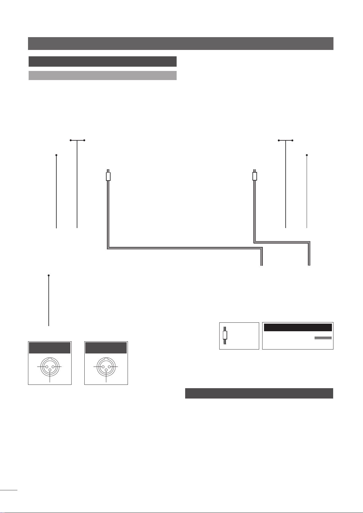
Endstufe NAP 500
32 NAP 500 – Anschlüsse
32.1 Anschluss an Netzteil NAP 500PS
Signalein-
gang Knl 1 (L)
Eingang links
(„Ch 1“)
Knl1
linker Lautsprecher
Netzanschluss
und Sicherung
Eingang rechts
(„Ch 2“)
-ve
nc Knl2
nc
-ve
Signaleingang
Knl 2 (R)
Kabelrichtungsmarkierung
rechter
Lautspre-
cher
Anschlusskabel
NAP-500-Burndy-Kabel
33 NAP 500/NAP 500PS – Technische Daten
D34
Ausgangsleistung: 140 Watt pro Kanal an 8 Ω,
Leistungsaufnahme:
Verstärkung: +29 dB
Eingangsimpedanz: 18 kΩ
Frequenzgang:
Abmessungen (H x B x T): NAP 500: 160 x 432 x 375 mm
NAP 500PS: 87 x 432 x 314 mm
Gewicht: NAP 500 – 25 kg
NAP 500PS – 15,4 kg
Netzversorgung: 100 V, 115 V oder 230 V; 50/60 Hz
60 VA im Ruhezustand
-3 dB bei 1,5 Hz und 100 kHz

Endstufe NAP 300
34 NAP 300 – Installation und Betrieb
Bevor Sie die Endstufe NAP 300 und das Netzteil NAP 300PS anschließen und einschalten,
sollten Sie die Geräte auf einem dafür vorgesehenen Rack platzieren. Schalten Sie zuerst
die Quellgeräte, dann (bei heruntergedrehtem Lautstärkeregler) die Vorstufe und zuletzt
die Endstufe ein. Der Netzschalter der Endstufe befindet sich an der Vorderseite des
Netzteils.
Beachten Sie beim Aufstellen der NAP 300, dass der Lüftereinlass an der Unterseite und
der Auslass an der Rückseite nicht verdeckt werden dürfen.
Die NAP 300 und das NAP 300PS sind sehr schwer – bitte bedenken Sie dies, wenn Sie die
Geräte hochheben oder umstellen wollen. Stellen Sie sicher, dass die Unterlage für das
Gewicht geeignet ist.
34.1 Allgemeine technische Hinweise
Die Minuspole der Ein- und Ausgänge eines Kanals sind
miteinander verbunden. Unabhängig davon, welche
anderen Geräte zusammen mit der Endstufe verwendet
werden, sollte der Schutzleiter stets angeschlossen sein. Er
erdet nur das Gehäuse und die Transformatorabschirmung
und ist nicht mit der Signalmasse verbunden. Zur
Vermeidung von Brummschleifen sollte die Signalmasse
der gesamten Anlage an einem einzigen Punkt mit dem
Schutzleiter verbunden sein.
34.2 Schutzschaltung
Die Geschwindigkeit des Lüfters der NAP 300 passt sich der
Wärmeentwicklung in der Endstufe an. Wenn die Endstufe
aufgrund längeren Betriebs bei hoher Lautstärke oder
mangelnden Luftaustauschs eine Temperatur von 70° C
erreicht, wird die Signalausgabe unterbrochen und der
Lüfter läuft so lange mit voller Geschwindigkeit, bis sich die
Endstufe abgekühlt hat. Dies kann einige Minuten dauern.
Die Endstufe muss in diesem Fall nicht ausgeschaltet
werden; es ist jedoch ratsam, die Vorstufe stummzuschalten
oder die Lautstärke herunterzudrehen, um einen
ungewollten Lautstärkesprung beim Wiedereinschalten der
Endstufe zu vermeiden.
WENN DIE SCHUTZSCHALTUNG DER ENDSTUFE EINSETZT, LIEGT
DIES IN DEN MEISTEN FÄLLEN AN ZU LANGEM BETRIEB BEI ZU
HOHER LÄUTSTÄRKE. DIE LAUTSTÄRKE SOLLTE IN SOLCHEN
FÄLLEN REDUZIERT WERDEN, DA DIE LAUTSPRECHER SONST
BESCHÄDIGT WERDEN KÖNNEN.
34.3 Lautsprecherkabel und -stecker
Zum Anschließen Ihrer Lautsprecher an die Ausgänge der
NAP 300 sollten Sie nur Naim-Audio-Lautsprecherkabel
verwenden. Lassen Sie die Lautsprecherkabel nur mit
den im Lieferumfang der Endstufe enthaltenen NaimAudio-Steckern konfektionieren; sie entsprechen den
europäischen Sicherheitsnormen.
DIE VERWENDUNG VON „HIGH DEFINITION“- ODER
SONSTIGEN SPEZIELLEN KABELN KANN ZUR BESCHÄDIGUNG
DER ENDSTUFE FÜHREN.
Achten Sie darauf, dass Sie die Lautsprecher richtig gepolt
anschließen, d.h., dass jeweils der Minuspol des Ausgangs
an den Minuspol des Lautsprechers und der Pluspol des
Ausgangs an den Pluspol des Lautsprechers angeschlossen ist.
D35
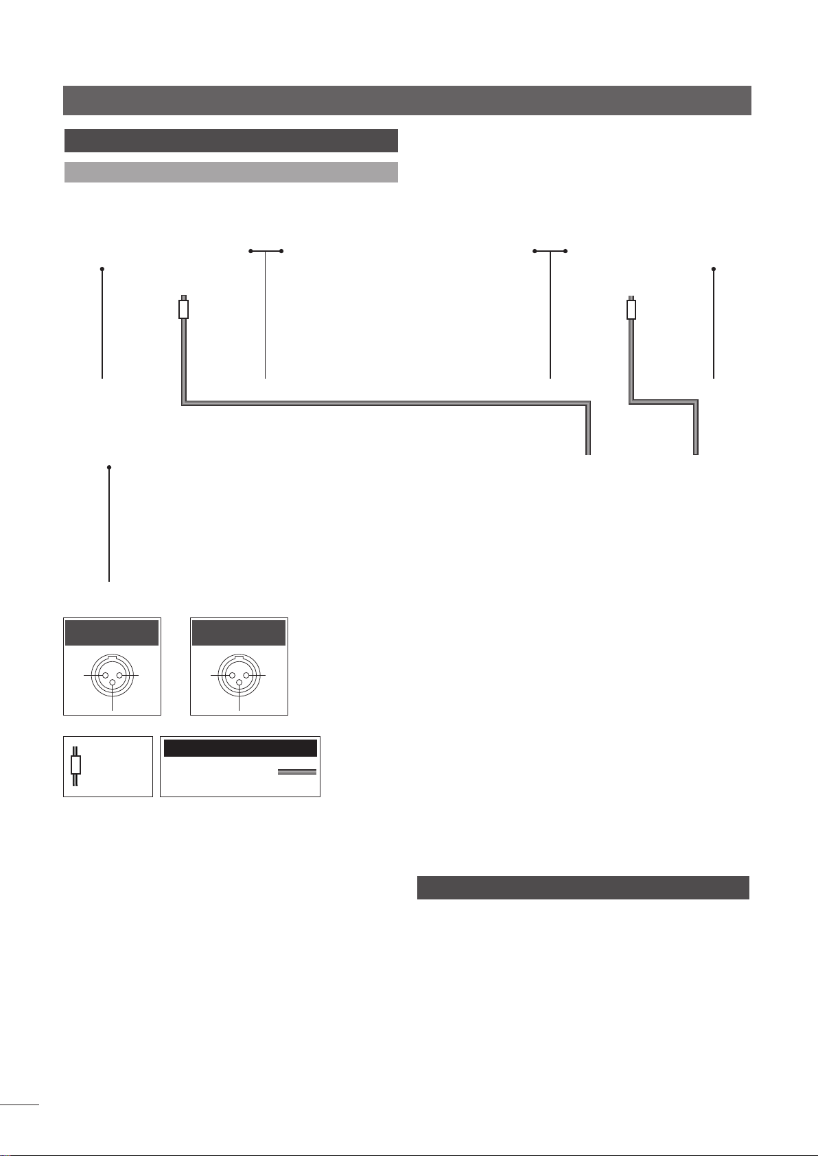
Endstufe NAP 300
35 NAP 300 – Anschlüsse
35.1 Anschluss an Netzteil NAP 300PS
Signaleingang
Knl 1 (L)
Eingang links
(„Ch 1“)
Knl1
Kabelrichtungsmarkierung
Netzanschluss und
Sicherung
Eingang rechts
(„Ch 2“)
-ve
nc Knl2
nc
Anschlusskabel
NAP-300-Burndy-Kabel
linker Lautsprecher
-ve
rechter Lautsprecher
Signaleingang
Knl 2 (R)
D36
36 NAP 300/NAP 300PS – Technische Daten
Ausgangsleistung: 90 Watt pro Kanal an 8 Ω,
Leistungsaufnahme:
Verstärkung: +29 dB
Eingangsimpedanz: 18 kΩ
Frequenzgang:
Abmessungen (H x B x T): 87 x 432 x 314 mm
(beide Geräte)
Gewicht: NAP 300 – 10,7 kg
NAP 300PS – 14,1 kg
Netzversorgung: 100 V, 115 V oder 230 V; 50/60 Hz
27 VA im Ruhezustand
-3 dB bei 2 Hz und 70 kHz

Endstufe NAP 250
37 NAP 250 – Installation und Betrieb
Bevor Sie die Endstufe NAP 250 anschließen und einschalten, sollten Sie das Gerät auf
einem dafür vorgesehenen Rack platzieren. Schalten Sie zuerst die Quellgeräte, dann
(bei heruntergedrehtem Lautstärkeregler) die Vorstufe und zuletzt die Endstufe ein. Der
Netzschalter der Endstufe befindet sich an der Vorderseite des Geräts.
Die NAP 250 ist sehr schwer – bitte bedenken Sie dies, wenn Sie das Gerät hochheben
oder umstellen wollen. Stellen Sie sicher, dass die Unterlage für das Gewicht geeignet ist.
37.1 Allgemeine technische Hinweise
Die Minuspole aller Ein- und Ausgänge sind miteinander
verbunden. Unabhängig davon, welche anderen Geräte
zusammen mit der Endstufe verwendet werden, sollte
der Schutzleiter stets angeschlossen sein. Er erdet nur
das Gehäuse und die Transformatorabschirmung und ist
nicht mit der Signalmasse verbunden. Zur Vermeidung
von Brummschleifen sollte die Signalmasse der gesamten
Anlage an einem einzigen Punkt mit dem Schutzleiter
verbunden sein.
37.2 Schutzschaltung
Wenn die Endstufe aufgrund längeren Betriebs bei hoher
Lautstärke eine Temperatur von 70° C erreicht, wird die
Stromzufuhr unterbrochen; das Logo an der Gerätefront
erlischt und leuchtet erst wieder, wenn sich die Endstufe
abgekühlt hat. Dies kann bis zu 30 Minuten dauern.
38 NAP 250 – Anschlüsse
38.1 Rückseite
WENN DIE SCHUTZSCHALTUNG DER ENDSTUFE EINSETZT, LIEGT
DIES IN DEN MEISTEN FÄLLEN AN ZU LANGEM BETRIEB BEI ZU
HOHER LÄUTSTÄRKE. DIE LAUTSTÄRKE SOLLTE IN SOLCHEN
FÄLLEN REDUZIERT WERDEN, DA DIE LAUTSPRECHER SONST
BESCHÄDIGT WERDEN KÖNNEN.
37.3 Lautsprecherkabel und -stecker
Zum Anschließen Ihrer Lautsprecher an die Ausgänge der
NAP 250 sollten Sie nur Naim-Audio-Lautsprecherkabel
verwenden. Lassen Sie die Lautsprecherkabel nur mit den
im Lieferumfang der Endstufe enthaltenen Naim-AudioSteckern konfektionieren; sie entsprechen den europäischen
Sicherheitsnormen.
DIE VERWENDUNG VON „HIGH DEFINITION“- ODER
SONSTIGEN SPEZIELLEN KABELN KANN ZUR BESCHÄDIGUNG
DER ENDSTUFE FÜHREN.
Achten Sie darauf, dass Sie die Lautsprecher richtig gepolt
anschließen, d.h., dass jeweils der Minuspol des Ausgangs
an den Minuspol des Lautsprechers und der Pluspol des
Ausgangs an den Pluspol des Lautsprechers angeschlossen ist.
Netzanschluss und
Sicherung
linker Lautsprecher
39 NAP 250 – Technische Daten
Ausgangsleistung: 80 Watt pro Kanal an 8 Ω,
Leistungsaufnahme:
Verstärkung: +29 dB
Eingangsimpedanz: 18 kΩ
Frequenzgang:
Abmessungen (H x B x T): 87 x 432 x 314 mm
Gewicht: 15,8 kg
Netzversorgung: 100 V, 115 V oder 230 V; 50/60 Hz
25 VA im Ruhezustand
-3 dB bei 2Hz und 65 kHz
rechter Lautsprecher
Signaleingang
(beide Kanäle)
Eingang
Knl1
Knl2
-ve
D37

Endstufe NAPV 145
40 NAPV 145 – Installation und Betrieb
Die NAPV 145 ist eine Mono-Endstufe für AV-Anwendungen. Bevor Sie die NAPV 145
anschließen und einschalten, sollten Sie das Gerät auf einem dafür vorgesehenen
Rack platzieren. Schalten Sie zuerst die Quellgeräte, dann (bei heruntergedrehtem
Lautstärkeregler) die Vorstufe und zuletzt die Endstufe ein. Der Netzschalter der Endstufe
befindet sich an der Vorderseite des Geräts.
Die NAPV 145 ist sehr schwer – bitte bedenken Sie dies, wenn Sie das Gerät hochheben
oder umstellen wollen. Stellen Sie sicher, dass die Unterlage für das Gewicht geeignet ist.
40.1 Allgemeine technische Hinweise
Die Minuspole des Eingangs und des Ausgangs sind
miteinander verbunden. Unabhängig davon, welche
anderen Geräte zusammen mit der Endstufe verwendet
werden, sollte der Schutzleiter stets angeschlossen sein. Er
erdet nur das Gehäuse und die Transformatorabschirmung
und ist nicht mit der Signalmasse verbunden. Zur
Vermeidung von Brummschleifen sollte die Signalmasse
der gesamten Anlage an einem einzigen Punkt mit dem
Schutzleiter verbunden sein.
40.2 Schutzschaltung
Wenn die Endstufe aufgrund längeren Betriebs bei hoher
Lautstärke eine Temperatur von 70° C erreicht, wird die
Stromzufuhr unterbrochen; das Logo an der Gerätefront
erlischt und leuchtet erst wieder, wenn sich die Endstufe
abgekühlt hat. Dies kann bis zu 30 Minuten dauern.
41 NAPV 145 – Anschlüsse
41.1 Rückseite
WENN DIE SCHUTZSCHALTUNG DER ENDSTUFE EINSETZT, LIEGT
DIES IN DEN MEISTEN FÄLLEN AN ZU LANGEM BETRIEB BEI ZU
HOHER LÄUTSTÄRKE. DIE LAUTSTÄRKE SOLLTE IN SOLCHEN
FÄLLEN REDUZIERT WERDEN, DA DIE LAUTSPRECHER SONST
BESCHÄDIGT WERDEN KÖNNEN.
40.3 Lautsprecherkabel und -stecker
Zum Anschließen Ihrer Lautsprecher an die Ausgänge der
NAPV 145 sollten Sie nur Naim-Audio-Lautsprecherkabel
verwenden. Lassen Sie die Lautsprecherkabel nur mit den
im Lieferumfang der Endstufe enthaltenen Naim-AudioSteckern konfektionieren; sie entsprechen den europäischen
Sicherheitsnormen.
DIE VERWENDUNG VON „HIGH DEFINITION“- ODER
SONSTIGEN SPEZIELLEN KABELN KANN ZUR BESCHÄDIGUNG
DER ENDSTUFE FÜHREN.
Achten Sie darauf, dass Sie die Lautsprecher richtig gepolt
anschließen, d.h., dass jeweils der Minuspol des Ausgangs
an den Minuspol des Lautsprechers und der Pluspol des
Ausgangs an den Pluspol des Lautsprechers angeschlossen ist.
D38
Netzanschluss und
Sicherung
42 NAPV 145 – Technische Daten
Ausgangsleistung: 80 Watt an 8 Ω,
Leistungsaufnahme:
Verstärkung: +29 dB
Eingangsimpedanz: 18 kΩ
Frequenzgang:
Abmessungen (H x B x T): 87 x 432 x 314 mm
Gewicht: 15,8 kg
Netzversorgung: 100 V, 115 V oder 230 V; 50/60 Hz
15 VA im Ruhezustand
-3 dB bei 2Hz und 65 kHz
Lautsprecher
Signaleingang
Eingang
i/p
nc
-ve

Endstufe NAP 200
43 NAP 200 – Installation und Betrieb
Bevor Sie die Endstufe NAP 200 anschließen und einschalten, sollten Sie das Gerät auf
einem dafür vorgesehenen Rack platzieren. Schalten Sie zuerst die Quellgeräte, dann
(bei heruntergedrehtem Lautstärkeregler) die Vorstufe und zuletzt die Endstufe ein. Der
Netzschalter der Endstufe befindet sich an der Vorderseite des Geräts.
Die NAP 200 kann bestimmte Naim-Vorstufen mit Strom versorgen. Das dazu benötigte
Gleichstromsignal wird am DIN-Eingang der NAP 200 geführt.
Die NAP 200 ist sehr schwer – bitte bedenken Sie dies, wenn Sie das Gerät hochheben
oder umstellen wollen. Stellen Sie sicher, dass die Unterlage für das Gewicht geeignet ist.
43.1 Allgemeine technische Hinweise
Die Minuspole aller Ein- und Ausgänge sind miteinander
verbunden. Unabhängig davon, welche anderen Geräte
zusammen mit der Endstufe verwendet werden, sollte
der Schutzleiter stets angeschlossen sein. Er erdet nur
das Gehäuse und die Transformatorabschirmung und ist
nicht mit der Signalmasse verbunden. Zur Vermeidung
von Brummschleifen sollte die Signalmasse der gesamten
Anlage an einem einzigen Punkt mit dem Schutzleiter
verbunden sein.
43.2 Schutzschaltung
Wenn die Endstufe aufgrund längeren Betriebs bei hoher
Lautstärke eine Temperatur von 70° C erreicht, wird die
Stromzufuhr unterbrochen; das Logo an der Gerätefront
erlischt und leuchtet erst wieder, wenn sich die Endstufe
abgekühlt hat. Dies kann bis zu 30 Minuten dauern.
44 NAP 200 – Anschlüsse
44.1 Rückseite
WENN DIE SCHUTZSCHALTUNG DER ENDSTUFE EINSETZT, LIEGT
DIES IN DEN MEISTEN FÄLLEN AN ZU LANGEM BETRIEB BEI ZU
HOHER LÄUTSTÄRKE. DIE LAUTSTÄRKE SOLLTE IN SOLCHEN
FÄLLEN REDUZIERT WERDEN, DA DIE LAUTSPRECHER SONST
BESCHÄDIGT WERDEN KÖNNEN.
43.3 Lautsprecherkabel und -stecker
Zum Anschließen Ihrer Lautsprecher an die Ausgänge der
NAP 200 sollten Sie nur Naim-Audio-Lautsprecherkabel
verwenden. Lassen Sie die Lautsprecherkabel nur mit den
im Lieferumfang der Endstufe enthaltenen Naim-AudioSteckern konfektionieren; sie entsprechen den europäischen
Sicherheitsnormen.
DIE VERWENDUNG VON „HIGH DEFINITION“- ODER
SONSTIGEN SPEZIELLEN KABELN KANN ZUR BESCHÄDIGUNG
DER ENDSTUFE FÜHREN.
Achten Sie darauf, dass Sie die Lautsprecher richtig gepolt
anschließen, d.h., dass jeweils der Minuspol des Ausgangs
an den Minuspol des Lautsprechers und der Pluspol des
Ausgangs an den Pluspol des Lautsprechers angeschlossen ist.
Netzanschluss
und Sicherung
linker Lautsprecher
45 NAP 200 – Technische Daten
Ausgangsleistung: 70 Watt pro Kanal an 8 Ω,
Leistungsaufnahme:
Verstärkung: +29 dB
Eingangsimpedanz: 18 kΩ
Frequenzgang:
Gleichstromausgang:
Abmessungen (H x B x T): 87 x 432 x 314 mm
Gewicht: 11,6 kg
Netzversorgung: 100 V, 115 V oder 230 V; 50/60 Hz
11 VA im Ruhezustand
-3 dB bei 2Hz und 65 kHz
24 V, 0,3 A
rechter Lautsprecher
Signaleingang
(beide Kanäle) und
Gleichstromaus-
gang
Eingang/Gleich-
stromausgang
Knl2
-ve
Knl1
24 V
0,3 A
D39

Endstufe NAP 155 XS
46 NAP 155 XS – Installation und Betrieb
Bevor Sie die Endstufe NAP 155 XS anschließen und einschalten, sollten Sie das Gerät auf
einem dafür vorgesehenen Rack platzieren. Schalten Sie zuerst die Quellgeräte, dann
(bei heruntergedrehtem Lautstärkeregler) die Vorstufe und zuletzt die Endstufe ein. Der
Netzschalter der Endstufe befindet sich an der Rückseite des Geräts.
Die NAP 155 XS kann bestimmte Naim-Vorstufen mit Strom versorgen. Das dazu benötigte
Gleichstromsignal wird am DIN-Eingang der NAP 155 XS geführt.
46.1 Allgemeine technische Hinweise
Die Minuspole aller Ein- und Ausgänge sind miteinander
verbunden. Unabhängig davon, welche anderen Geräte
zusammen mit der Endstufe verwendet werden, sollte
der Schutzleiter stets angeschlossen sein. Er erdet nur
das Gehäuse und die Transformatorabschirmung und ist
nicht mit der Signalmasse verbunden. Zur Vermeidung
von Brummschleifen sollte die Signalmasse der gesamten
Anlage an einem einzigen Punkt mit dem Schutzleiter
verbunden sein.
46.2 Schutzschaltung
Wenn die Endstufe aufgrund längeren Betriebs bei hoher
Lautstärke eine Temperatur von 70° C erreicht, wird die
Stromzufuhr unterbrochen; das Logo an der Gerätefront
erlischt und leuchtet erst wieder, wenn sich die Endstufe
abgekühlt hat. Dies kann bis zu 30 Minuten dauern.
47 NAP 155 XS – Anschlüsse
47.1 Rückseite
WENN DIE SCHUTZSCHALTUNG DER ENDSTUFE EINSETZT, LIEGT
DIES IN DEN MEISTEN FÄLLEN AN ZU LANGEM BETRIEB BEI ZU
HOHER LÄUTSTÄRKE. DIE LAUTSTÄRKE SOLLTE IN SOLCHEN
FÄLLEN REDUZIERT WERDEN, DA DIE LAUTSPRECHER SONST
BESCHÄDIGT WERDEN KÖNNEN.
46.3 Lautsprecherkabel und -stecker
Zum Anschließen Ihrer Lautsprecher an die Ausgänge der
NAP 155 XS sollten Sie nur Naim-Audio-Lautsprecherkabel
verwenden. Lassen Sie die Lautsprecherkabel nur mit den
im Lieferumfang der Endstufe enthaltenen Naim-AudioSteckern konfektionieren; sie entsprechen den europäischen
Sicherheitsnormen.
DIE VERWENDUNG VON „HIGH DEFINITION“- ODER
SONSTIGEN SPEZIELLEN KABELN KANN ZUR BESCHÄDIGUNG
DER ENDSTUFE FÜHREN.
Achten Sie darauf, dass Sie die Lautsprecher richtig gepolt
anschließen, d.h., dass jeweils der Minuspol des Ausgangs
an den Minuspol des Lautsprechers und der Pluspol des
Ausgangs an den Pluspol des Lautsprechers angeschlossen ist.
D40
Netz-
schalter
Netzanschluss und
Sicherung
linker Lautsprecher
48 NAP 155 XS – Technische Daten
Ausgangsleistung: 60 Watt pro Kanal an 8 Ω,
Leistungsaufnahme:
Verstärkung: +29 dB
Eingangsimpedanz: 18 kΩ
Frequenzgang:
Gleichstromausgang:
Abmessungen (H x B x T): 70 x 432 x 301 mm
Gewicht: 7,5 kg
Netzversorgung: 100 V, 115 V oder 230 V; 50/60 Hz
10 VA im Ruhezustand
-3 dB bei 3 Hz und 50 kHz
24 V, 0,25 A
rechter Lautsprecher
Signaleingang
(beide Kanäle) und
Gleichstromaus-
gang
Eingang/Gleich-
stromausgang
Knl2
-ve
Knl1
24 V
0,25 A

Endstufe NAP 100
49 NAP 100 – Installation und Betrieb
Bevor Sie die Endstufe NAP 100 anschließen und einschalten, sollten Sie das Gerät auf
einem dafür vorgesehenen Rack platzieren. Schalten Sie zuerst die Quellgeräte, dann (bei
heruntergedrehtem Lautstärkeregler) die Vorstufe und zuletzt die Endstufe ein. Achten Sie
darauf, dass der Verstärker ausreichend belüftet ist. Der Netzschalter der Endstufe befindet
sich an der Rückseite des Geräts.
49.1 Allgemeine technische Hinweise
Der Schutzleiter erdet nur das Gehäuse und die
Transformatorabschirmung und ist nicht mit der Signalmasse
verbunden. Unabhängig davon, welche anderen Geräte
zusammen mit der Endstufe verwendet werden, sollte
der Schutzleiter stets angeschlossen sein. Zur Vermeidung
von Brummschleifen sollte die Signalmasse der gesamten
Anlage an einem einzigen Punkt mit dem Schutzleiter
verbunden sein.
Die Cinchbuchsen und die DIN-Buchse für den
Signaleingang sind parallel geschaltet und sollten nicht
gleichzeitig verwendet werden.
49.2 Schutzschaltung
Die NAP 100 sollte unter normalen Umständen stets
eingeschaltet bleiben. Wenn der Kühlkörper in der
Endstufe aufgrund längeren Betriebs bei hoher Lautstärke
eine Temperatur von 70° C erreicht, wird die Stromzufuhr
unterbrochen, bis sich die Endstufe abgekühlt hat. Dies
kann bis zu 30 Minuten dauern.
50 NAP 100 – Anschlüsse
50.1 Rückseite
WENN DIE SCHUTZSCHALTUNG DER ENDSTUFE EINSETZT, LIEGT
DIES IN DEN MEISTEN FÄLLEN AN ZU LANGEM BETRIEB BEI ZU
HOHER LÄUTSTÄRKE. DIE LAUTSTÄRKE SOLLTE IN SOLCHEN
FÄLLEN REDUZIERT WERDEN, DA DIE LAUTSPRECHER SONST
BESCHÄDIGT WERDEN KÖNNEN.
49.3 Lautsprecherkabel und -stecker
An der Geräterückseite befinden sich zwei Ausgänge
zum Anschließen von Stereo-Lautsprechern. Lassen Sie
Ihre Lautsprecherkabel nur mit den im Lieferumfang
des Verstärkers enthaltenen Naim-Audio-Steckern
konfektionieren; sie entsprechen den europäischen
Sicherheitsnormen. Wir empfehlen die Verwendung von
Naim-Lautsprecherkabeln, es können jedoch auch viele
andere Kabeltypen mit dem NAP 100 verwendet werden.
Achten Sie darauf, dass Sie die Lautsprecher richtig gepolt
anschließen, d.h., dass jeweils der Minuspol des Ausgangs
an den Minuspol des Lautsprechers und der Pluspol des
Ausgangs an den Pluspol des Lautsprechers angeschlossen ist.
Lautsprecher
Netzschalter
linker
Netzanschluss und
Sicherung
rechter
Lautsprecher
Cincheingang
Knl1(L) & Knl2(R)
DIN-Eingang
Knl1(L) & Knl2(R)
51 NAP 100 – Technische Daten
Ausgangsleistung: 50 Watt pro Kanal an 8 Ω
Leistungsaufnahme:
Verstärkung: +29 dB
Eingangsimpedanz: 18 kΩ
Frequenzgang:
Abmessungen (H x B x T): 87 x 207 x 314 mm
Gewicht: 5,6 kg
Netzversorgung: 100 V, 115 V oder 230 V; 50/60 Hz
15 VA im Ruhezustand
-3 dB bei 3,5 Hz und 69 kHz
Eingang – links
und rechts
Knl2
-ve
Knl
nc
D41

Konformitätserklärung
52 Konformitätserklärung
Naim-Audio-Produkte sind mit folgenden Richtlinien konform:
Niederspannungsrichtlinie 2006/95/EG
EMV-Richtlinie 2004/108/EG
EG-Richtlinie 2011/65/EG (Beschränkung der Verwendung bestimmter gefährlicher Stoffe in
Elektro- und Elektronikgeräten)
EG-Richtlinie 2002/96/EG (Entsorgung von Elektro- und Elektronik-Altgeräten)
EG-Richtlinie 2005/32/EG (Ökodesign-Richtlinie)
Naim-Audio-Produkte entsprechen folgenden Normen:
EN 60065: Audio-, Video- und ähnliche elektronische Geräte – Sicherheitsanforderungen
EN 55013: Ton- und Fernseh-Rundfunkempfänger und verwandte Geräte
EN 55020: Störfestigkeit von Rundfunkempfängern und verwandten Geräten
EN 61000-3-2: Grenzwerte für Oberschwingungsströme
EN 61000-3-3: Begrenzung von Spannungsschwankungen und Flicker in öffentlichen
D42
Naim Audio Ltd, Southampton Road, Salisbury, England SP1 2LN
Tel: +44 (0) 1722 426600 Fax: +44 (0)871 230 1012
W: www.naimaudio.com
Part No. 12-001-0041 Iss. 6G
Produkte, die mit der durchgestrichenen Mülltonne
gekennzeichnet sind, dürfen nicht mit dem Hausmüll
entsorgt werden. Diese Produkte müssen Einrichtungen
übergeben werden, die sie recyceln und anfallende
Schadstoffe sachgemäß entsorgen können. Die
Adressen solcher Einrichtungen erfahren Sie von
Ihrem örtlichen Umweltamt. Recycling und die
Schadstoffbeseitigung tragen zur Schonung von
Ressourcen und zum Schutz der Umwelt bei.
MANUEL D’UTILISATION
PREAMPLIFICATEURS
AMPLIFICATEURS INTEGRES, AMPLIFICATEURS DE PUISSANCE
ENGLISH DEUTSCH FRANÇAIS ITALIANO

CONSIGNES DE SECURITE
Afin de respecter les réglementations Européennes de
sécurité en vigueur, il est impératif d’utiliser les connecteurs
d’enceintes, fournis avec les amplificateurs et enceintes
Naim.
Ne permettre en aucun cas de modification de votre
matériel Naim sans prendre contact au préalable avec
l’usine Naim, votre revendeur ou votre distributeur. Toute
modification non autorisée entraînerait la nullité de la
garantie.
Le matériel ne doit pas être exposé aux coulures ni aux
éclaboussures, donc aucun objet contenant un liquide,
comme par exemple un vase, ne doit être posé dessus.
Pour votre propre sécurité, ne jamais ouvrir le matériel Naim
sans l’avoir débranché du secteur.
Attention : Les appareils de classe 1 doivent être branchés
exclusivement à une prise secteur munie d’une protection
par mise à la terre.
Lorsqu’une prise secteur ou un prolongateur est utilisé
comme dispositif de débranchement, celui-ci doit rester
facilement accessible. Pour débrancher le matériel,
débrancher la prise de courant au niveau de la prise
murale.
L’étiquette suivante est accrochée à tout matériel
électrique branché sur le secteur.
WARNING
THIS APPARATUS
MUST BE EARTHED
(ATTENTION: CET APPAREIL DOIT ETRE MIS A LA TERRE)
NOTA
Cet appareil a été vérifié et certifié conforme aux
exigences CEM et aux Normes de Sécurité, et le cas
échéant, est également conforme aux limites admissibles
pour les dispositifs numériques de classe B, selon la Partie 15
de la Réglementation FCC.
Ces limites visent à assurer une protection raisonnable
contre les perturbations nuisibles dans les installations
privées. Le matériel génère, utilise et peut émettre des
fréquences radio, et en cas d’utilisation ou d’installation
contraire aux directives, peut perturber les communications
radio. il n’y a cependant aucune garantie qu’une
installation donnée ne génère pas d’interférences radio.
Si ce matériel perturbe les réceptions radio ou télévisées,
ce qui peut être confirmé en l’allumant et l’éteignant, il est
préconisé d’adopter une ou plusieurs des mesures suivantes :
Réorienter ou repositionner l’antenne de réception.
Augmenter la distance entre le matériel et le récepteur.
Brancher le matériel sur une prise murale raccordée à un
circuit différent de celui du récepteur.
Consulter votre revendeur Naim ou un technicien spécialisé
en radio/TV.
Table des Matières
Page Section
F1 1 Raccordements
F1 2 Alimentation secteur
F2 3 Généralités d’installation
F3 4 NAC 552 Introduction et Installation
F4 5 NAC 552 Commandes et Raccordements
F5 6 NAC 552 Spécifications
F6 7 NAC 252 Introduction et Installation
F6 8 NAC 252 Commandes et Raccordements
F7 9 NAC 252 Spécifications
F8 10 NAC 282 Introduction et Installation
F8 11 NAC 282 Commandes et Raccordements
F10 12 NAC 282 Spécifications
F11 13 NAC 202 Introduction et Installation
F11 14 NAC 202 Commandes et Raccordements
F12 15 NAC 202 Spécifications
F13 16 NAC 152 XS Introduction et Installation
F14 17 NAC 152 XS Commandes et Raccordements
F16 18 NAC 152 XS Spécifications
F17 19 Supernait Introduction et Installation
F19 20 Supernait Commandes et Raccordements
F21 21 Supernait Spécifications
F22 22 Nait XS Introduction et Installation
F23 23 Nait XS Commandes et Raccordements
F25 24 Nait XS Spécifications
F26 25 Nait 5i Introduction et Installation
F26 26 Nait 5i Commandes et Raccordements
F27 27 Nait 5i Spécifications
F28 28 Fonctionnement des Préamplificateurs et
Amplificateurs Intégrés
F31 29 Télécommande R-com
F32 30 Télécommande NARCOM 4
F33 31 NAP 500 Installation et Fonctionnement
F34 32 NAP 500 Raccordements
F34 33 NAP 500 Spécifications
F35 34 NAP 300 Installation et Fonctionnement
F36 35 NAP 300 Raccordements
F36 36 NAP 300 Spécifications
F37 37 NAP 250 Installation et Fonctionnement
F37 38 NAP 250 Raccordements
F37 39 NAP 250 Spécifications
F38 40 NAPV 145 Installation et Fonctionnement
F38 41 NAPV 145 Raccordements
F38 42 NAPV 145 Spécifications
F39 43 NAP 200 Installation et Fonctionnement
F39 44 NAP 200 Raccordements
F39 45 NAP 200 Spécifications
F40 46 NAP 155 XS Installation et Fonctionnement
F40 47 NAP 155 XS Raccordements
F40 48 NAP 155 XS Spécifications
F41 49 NAP 100 Installation et Fonctionnement
F41 50 NAP 100 Raccordements
F41 51 NAP 100 Spécifications
F42 52 Déclarations de Conformité

Introduction
La conception des produits Naim Audio vise en premier lieu les performances. Une installation minutieuse est nécessaire pour assurer la réalisation de tout leur potentiel. Ce manuel
couvre les
commence par des informations générales concernant l’installation et les avertissements
réglementaires sur la sécurité. Les informations spécifiques aux différents produits commencent en Section 4.
preamplificateurs, amplificateurs integres et amplificateurs de puissance. Le manuel
1 Branchements
Pour des raisons de sécurité et pour garantir les performances, il est primordial de ne pas modifier les câbles
standards fournis avec l’appareil.
1.1 Câbles de modulation
Si plusieurs possibilités sont offertes au niveau de l’installation
de votre matériel, les prises DIN doivent être utilisées en
préférence aux prises RCA. Une extrémité de chaque câble
de modulation Naim est pourvue d’un collier identifiant le
sens de branchement optimal. Ce collier indique l’extrémité
qui doit être branchée à la source du signal.
Les prises de modulation mâles et femelles doivent
être maintenues propres et exemptes de corrosion. La
manière la plus facile de les nettoyer est d’éteindre tout le
matériel, débrancher toutes les prises mâles de leurs prises
femelles, puis de les y réinsérer. Les produits de nettoyage
des contacts et dispositifs “d’amélioration” ne sont pas
recommandés, car le film déposé peut dégrader le son.
1.2 Câbles de raccordement des enceintes
Les câbles de raccordement des enceintes sont d’une
importance primordiale. Ils doivent avoir une longueur
minimum de 3,5 mètres et doivent être de longueur égale.
La longueur maximum généralement recommandée, est
de 20 mètres, néanmoins, des câbles plus longs peuvent
être utilisés avec certains amplificateurs Naim.
La conception de certains amplificateurs Naim nécessite
l’utilisation exclusive de câble de raccordement des
enceintes Naim, et l’utilisation de câbles de fabrication
différente risque de dégrader les performances, voire
endommager l’amplificateur. Les autres amplificateurs
Naim peuvent être utilisés avec n’importe quel câble de
raccordement d’enceintes de bonne qualité, mais nous
recommandons néanmoins l’utilisation de câbles Naim. Le
câble Naim est directionnel et doit être orienté de manière
que les flèches imprimées sur l’isolation soient dirigées vers
les enceintes. Les connecteurs d’enceintes Naim livrés sont
conformes à la réglementation européenne sur la sécurité,
et doivent être utilisés.
Contacter votre revendeur pour de plus amples
informations concernant les câbles d’enceintes et les
connecteurs.
2 Alimentation électrique
Ne pas câbler de résistances sensibles à la tension, ni de
réducteur de bruit au niveau des prises secteurs, car ceux-ci
dégradent l’alimentation et le son.
2.1 Câblage de la prise d’alimentation électrique
Dans certains pays, la prise secteur doit être installée sur le
câble d’alimentation fourni. Comme les couleurs des fils du
câble d’alimentation peuvent ne pas correspondre aux
codes couleurs identifiant les cosses de la prise, respecter
impérativement le schéma suivant :
Le fil VERT ET JAUNE doit être relié à la cosse de la prise
identifiée par la lettre E ou par le symbole de sécurité de la
terre, ou de couleur VERTE ou VERTE ET JAUNE.
Le fil BLEU doit être relié à la cosse de la prise identifiée par
la lettre N ou de couleur NOIRE.
Le fil MARRON doit être relié à la cosse de la prise identifiée
par la lettre L ou de couleur ROUGE.
2.2 Fusibles de protection
Le matériel Naim branché sur secteur est protégé par un
fusible d’alimentation, en face arrière, à proximité de la
prise femelle d’alimentation secteur. En cas de nécessité,
remplacer le fusible exclusivement avec le fusible de
rechange fourni, ou par un fusible identique. En cas de fusible
grillé à répétition, contacter votre revendeur ou Naim pour
étudier le problème.
2.3 Prises secteur moulées
Si, pour une raison quelconque, le câble d’alimentation
est sectionné afin de déposer la prise secteur moulée, la
prise doit IMPERATIVEMENT être éliminée d’une manière qui
la rend complètement inutilisable. Un risque considérable
de choc électrique existe si jamais la prise sectionnée est
insérée dans une prise murale.
2.4 Circuits et câbles secteurs
Les systèmes hi-fi partagent habituellement le circuit
secteur avec d’autres appareils ménagers dont certains
peuvent déformer la forme de l’onde de l’alimentation
secteur. Cette déformation peut, à son tour, entraîner
un bourdonnement mécanique dans les transformateurs
d’alimentation. Certains transformateurs Naim sont de
dimensions importantes, ce qui les rend particulièrement
sensibles à ce genre de déformation, et il faudra
éventuellement en tenir compte lors du choix de
l’implantation de votre matériel.
Le bourdonnement des transformateurs n’est pas transmis
par les enceintes et n’exerce aucune influence sur les
performances du système, néanmoins, l’utilisation d’un circuit
secteur séparé permet souvent de le réduire. Un tel circuit
(de préférence protégé par un fusible de 30 ou 45 ampères)
conduira aussi, en général, à des performances accrues. Pour
l’installation d’un circuit secteur séparé, demander l’avis d’un
électricien qualifié.
F1

Introduction
Il n’est pas recommandé de remplacer les cordons et
prises d’alimentation fournies par d’autres modèles, car
ceux-ci ont été sélectionnés pour assurer les meilleures
performances possibles.
3 Installation générale
Le matériel Naim est conçu pour garantir les meilleures
performances possibles en évitant tant que possible, tout
compromis. Ceci peut donner lieu à des circonstances qui
sont inattendues. Les notes ci-dessous contiennent des recommandations spécifiques au matériel Naim, ainsi que des avertissements plus généraux concernant l’utilisation des appareils
audio domestiques. Veuillez les étudier attentivement.
3.1 Implantation du matériel
Afin de diminuer le risque de bourdonnement audible
par les enceintes, les alimentations et amplificateurs
de puissance doivent être positionnés à une distance
raisonnable du reste du matériel. La distance de séparation
maximale pour le matériel connecté est celle admise par le
cordon de modulation standard fourni.
Certains équipements Naim sont particulièrement lourds.
Vérifier le poids du matériel avant de le soulever et si
nécessaire travailler à plusieurs personnes pour pouvoir le
mettre en place en toute sécurité.
Assurez-vous que votre support de matériel ou votre table,
est capable de résister au poids et assure une bonne
stabilité.
Certaines enceintes et leurs supports sont équipés de
pointes. Faire très attention en les mettant en place ou
en les déplaçant, pour éviter toute possibilité de blessure
corporelle ou d’endommagement des câbles ou des
surfaces de soutien. Des dispositifs de protection du sol sont
disponibles auprès de votre revendeur, afin de protéger les
sols non munis de tapis.
3.2 Mise sous tension
Les sources et les alimentations doivent être mises sous
tension avant les amplificateurs de puissance. Toujours
éteindre les amplificateurs et attendre au moins une minute
avant de brancher ou débrancher de câbles. Toujours
utiliser l’interrupteur de mise sous tension plutôt qu’un
interrupteur de prise murale.
Un coup sourd peut être émis par les enceintes à la mise
sous tension des amplificateurs de puissance. Ceci est tout
à fait normal, ne déteriore pas les enceintes, et n’est pas
indicatif d’un défaut ou problème. Un léger “ploc” peut
également être émis peu de temps après avoir éteint le
matériel.
3.3 Rodage
Le matériel Naim demande un temps considérable de
rodage avant de délivrer toutes ses performances. Cette
période peut varier, mais sous certaines conditions, la
qualité du son peut continuer de s’améliorer pendant un
mois. Des performances meilleures et plus homogènes sont
obtenues lorsque le matériel est laissé sous tension pendant
longtemps. Il faut cependant penser que le matériel sous
tension est plus susceptible d’être endommagé en cas
d’orage.
3.4 Interférences radio
Sous certaines conditions, selon le lieu du domicile et
de la configuration de la mise à la terre, il est possible
d’entendre des interférences radio. Les réglementations
de radiocommunications dans certain pays admettent
des niveaux d’émission en fréquence radio très importants,
et le choix ainsi que le positionnement précis du matériel
peuvent devenir très critiques. La sensibilité aux interférences
radio est liée à l’importante bande passante nécessaire à
la bonne qualité du son. Un kit de filtre des fréquences radio
est disponible pour certains matériels Naim, mais la qualité
du son diminue progressivement au fur et à mesure de
l’installation des différents éléments du kit.
3.5 Précautions à prendre contre la foudre
Le matériel Naim est susceptible d’être endommagé par la
foudre et doit être éteint et débranché du secteur lorsqu’il
y a un risque d’orage. Pour une protection totale, toutes les
prises secteur et les éventuels câbles d’antennes doivent
être débranchés en cas d’inutilisation.
3.6 En cas de problème
La protection des consommateurs varie d’un pays à
l’autre. Dans la plupart des pays, un revendeur doit être
prêt à reprendre tout matériel vendu si celui-ci ne peut pas
fonctionner correctement. Le problème peut provenir d’un
défaut du système ou de son installation, il est donc essentiel
d’utiliser toutes les connaissances de diagnostic de votre
revendeur. Veuillez contacter votre revendeur ou Naim
directement, si vous n’arrivez pas à résoudre un problème.
Certains matériels Naim existent en version spéciale pour
les différents pays, et il n’est donc pas pratique d’organiser
des garanties internationales. Veuillez donc interroger
votre revendeur concernant les garanties applicables
dans votre pays. Vous pouvez néanmoins contacter Naim
directement, si nécessaire, pour des renseignements et
recommandations.
3.7 Réparation et remise à niveau
Il est essentiel que les réparations et les remises à niveau
soient effectuées exclusivement par un revendeur Naim
autorisé, ou à l’usine même de Naim. De nombreux
composants sont spécifiquement fabriqués, testés ou
appairés et une pièce de remplacement adaptée n’est
souvent pas disponible d’une autre source.
Le contact direct avec Naim pour obtenir des informations
concernant les réparations ou les remises à niveau, doit être
effectué d’abord auprès du Service à la clientèle :
Téléphone : +44 (0)1722 42 66 00
E-mail: info@naimaudio.com
Veuillez indiquer le numéro de série du produit concerné
(indiqué en face arrière) dans toute communication.
F2

Préamplificateur NAC 552
4 NAC 552 Introduction et Installation
Le préamplificateur NAC 552 ne dispose pas d’alimentation interne, et ne peut être
utilisé qu’en association avec une alimentation NAC 552PS. Le schéma 5.3 illustre les
raccordements entre le NAC 552 et son alimentation.
Les quatre vis de transport en dessous du boîtier du NAC 552 doivent être retirées
avant son utilisation, et doivent être remises en place en cas de conditionnement pour
expédition. Ces vis de transport ne doivent être utilisées avec aucun autre appareil Naim.
Ne jamais retourner le NAC 552 lorsque les vis de transport sont retirées.
Le préamplificateur et son alimentation doivent être installés sur un support dédié,
spécialement conçu à cet effet. Ne poser ni l’un ni l’autre directement sur un autre
appareil. Bien vérifier que le préamplificateur est de niveau.
Le préamplificateur et son alimentation doivent être installés dans leur position définitive
avant de brancher les câbles et de les mettre en marche. Vérifier que les amplificateurs
de puissance sont éteints et que le volume du préamplificateur est diminué avant
d’allumer l’alimentation. Le bouton marche/arrêt est situé en façade de l’alimentation.
L’alimentation est lourde, et il est important de faire attention pour la soulever ou la déplacer.
Bien s’assurer que la surface devant la recevoir est capable de résister à son poids.
Les paragraphes ci-dessous de la Section 4 décrivent les caractéristiques d’installation et
les fonctions spécifiques du NAC 552. Les caractéristiques de fonctionnement communes
à tous les préamplificateurs et amplificateurs intégrés, figurent à la Section 28.
Les télécommandes R-Com et NARCOM 4 sont toutes les deux fournies d’origine avec le
NAC 552. La télécommande R-Com est adaptée aux utilisations courantes, alors que la
NARCOM 4 sert à la programmation et à la configuration par télécommande.
4.1 Entrées Sources et Sorties d’Enregistrement
Les boutons de sélection des entrées, disposés dans la
rangée supérieure, servent à sélectionner le signal source
à diriger vers l’amplificateur de puissance et les enceintes.
Les boutons correspondants dans la rangée inférieure
servent à sélectionner le signal à diriger vers les sorties
d’enregistrement du préamplificateur.
La séparation des boutons de sélection des sources et
d’enregistrement permet d’écouter une source (par
exemple le lecteur de CD) alors qu’une autre source (par
exemple le tuner) est sélectionnée pour l’enregistrement.
Note : Il est possible de verrouiller les commandes
d’enregistrement afin d’éviter une désélection accidentelle
lors de l’enregistrement. Le verrouillage d’enregistrement est
sélectionné ou désélectionné en appuyant sur le bouton
source mono quatre fois en moins de six secondes.
Le NAC 552 est équipé de témoins lumineux en façade
arrière au-dessus de chaque prise d’entrée. Ces témoins
s’éclairent pour indiquer l’entrée sélectionnée et
servent à configurer la cartographie des entrées et à la
programmation.
4.2 Affectation des prises d’entrées
Les différentes prises d’entrées du NAC 552 peuvent être
sélectionnées à partir de n’importe lequel des boutons.
Par exemple, alors que la configuration par défaut du
NAC 552 consiste à sélectionner la prise d’entrée N° 2 au
moyen du bouton de sélection CD, la programmation
personnalisée permet de sélectionner n’importe laquelle
des prises d’entrées au moyen du bouton de sélection CD.
L’affectation de chaque bouton d’enregistrement suit celle
du bouton correspondant de sélection de source.
La configuration de l’affectation des entrées est accessible
par le mode programmation du NAC 552. Pour activer
(ou quitter) le mode programmation, appuyer et
maintenir la touche prog de la télécommande (en mode
préamplificateur). L’activation du mode programmation
est indiquée par le clignotement du témoin lumineux de
la commande de volume en façade et par l’extinction de
l’éclairage des boutons de sélection d’enregistrement.
Note : Si aucune fonction n’est utilisée dans les cinq minutes
qui suivent l’activation du mode programmation, le NAC
552 se remet automatiquement en mode normal.
N’importe lequel des six boutons de sélection de source
peut être affecté à n’importe laquelle des entrées stéréo
(sept prises DIN et deux paires de prises RCA) en façade
arrière. En mode programmation, lorsqu’une entrée source
est sélectionnée, un témoin lumineux s’éclaire en façade
arrière pour indiquer la prise d’entrée qui y est affectée.
Pour modifier la prise d’entrée affectée à un bouton de
sélection de source, appuyer sur le bouton de source
correspondant puis utiliser les boutons mute et mono pour
déplacer la prise d’entrée sélectionnée. Si la prise d’entrée
choisie est déjà affectée à un bouton de sélection de
source, le témoin lumineux au-dessus de la prise d’entrée se
mettra à clignoter. Il est possible d’affecter une même prise
d’entrée à plusieurs boutons de sélection de source, mais
il n’est PAS possible d’affecter plusieurs prises d’entrée au
Les caractéristiques
de fonctionnement
communes à tous
les préamplificateurs
et amplificateurs
intégrés, figurent à la
Section 28.
F3

Préamplificateur NAC 552
même bouton de sélection de source. Les fonctions record
mute et mono de la télécommande peuvent également
être utilisées pour configurer l’affectation des entrées.
Pour quitter le mode de programmation, appuyer et
maintenir la touche prog de la télécommande jusqu’à
la restitution de l’éclairage des boutons de sélection
d’enregistrement et l’arrêt du clignotement du témoin
lumineux du bouton de volume.
Le Tableau 4.3 indique l’affectation par défaut des prises
d’entrée du NAC 552.
4.3 Types de Prises et Affectation par Défaut
N° Prise Caractéristiques Affectation par défaut du bouton
d’entrée de la prise de sélection de source
1 Entrée DIN Non affectée
2 Entrée DIN CD
3 Entrée DIN TUNER
4 Entrée/Sortie DIN avec capacité “gain unité” TAPE
5 Entrée/Sortie DIN avec capacité “gain unité” AV
6 Entrée/Sortie DIN AUX 1
7 Entrée DIN, avec alimentation pour étage phono AUX 2
8 Paire RCA Non affectée
9 Paire RCA Non affectée
5 Commandes et Raccordements du NAC 552
5.1 Façade avant du NAC 552
volume
balance
5.2 Façade arrière du NAC 552
entr 1 entr 2 entr 3
entr 4
entr 5 entr 6 entr 8
rangée supérieure
(sources d’entrées
rangée inférieure
(enregistrement)
mono
terre signal entr 9
mute
entr 7 entrée RC5
voie 1
voie 1
voie 2
voie 2
sélection
des sources
d’entrée et
d’enregistrement
NAC 552PS
NAC 552PS
F4
Entrées 1, 2 & 3
v1
v2
nég
nc
nc
Entrées 4, 5 & 6
v1
v1
v2
sortie
v2
sortie
nég
pos
v2
Entrée 7
pos
v1
nég

Préamplificateur NAC 552
5.3 NAC 552 relié au NAC 552PS
Note : Pour garantir des performances optimales, les câbles Burndy et
DIN à 5 broches doivent cheminer le plus près possible l’un de l’autre.
sortie signal complémentaire
entrée secteur et
fusible
6 Spécifications NAC 552 / NAC 552PS
Sensibilité des entrées : 75mV, 47kΩ
Marge de puissance: 40dB (toutes entrées, toutes
fréquences audio)
Niveau de sortie principal : 0,775V, < 50Ω
Niveau de sortie Tape : 75mV, 600Ω
Sorties d’alimentation aux : Pour étage phono Naim
Dimensions (H x L x P) : 87 x 432 x 314mm chacun
Poids : NAC 552 : 12,9 kg
NAC 552PS : 13,9kg
Tension de secteur : 100V, 115V ou 230V, 50/60Hz
(NAC 552PS)
vers amplicateurs de puissance
monos ou double-monos
indicateur
d’orientation
de câble
vers amplicateurs
de puissance
stéréos
Câbles de modulation
NAC 552 Burndy
5-br à 5-br DIN à 240°
F5

Préamplificateur NAC 252
7 NAC 252 Introduction et Installation
Le préamplificateur NAC 252 ne dispose pas d’alimentation interne, et ne peut être utilisé
qu’en association avec une alimentation externe Supercap. Le schéma 8.3 illustre les
raccordements entre le NAC 252 et son alimentation.
Le préamplificateur et son alimentation doivent être installés sur un support dédié,
spécialement conçu à cet effet. Ne poser ni l’un ni l’autre directement sur un autre
appareil. Bien vérifier que le préamplificateur est de niveau.
Le préamplificateur et son alimentation doivent être installés dans leur position définitive
avant de brancher les câbles et de les mettre en marche. Vérifier que les amplificateurs
de puissance sont éteints et que le volume du préamplificateur est diminué avant
d’allumer l’alimentation. Le bouton marche/arrêt est situé en façade de l’alimentation.
L’alimentation est lourde, et il est important de faire attention pour la soulever ou la
déplacer. Bien s’assurer que la surface devant la recevoir est capable de résister à son
poids.
Les paragraphes ci-dessous de la Section 7 décrivent les caractéristiques d’installation et
les fonctions spécifiques du NAC 252. Les caractéristiques de fonctionnement communes
à tous les préamplificateurs et amplificateurs intégrés, figurent à la Section 28.
Les caractéristiques
de fonctionnement
communes à tous
les préamplificateurs
et amplificateurs
intégrés, figurent à la
Section 28.
7.1 Entrées Sources et Sorties d’Enregistrement
Les boutons de sélection des entrées, disposés dans la
rangée supérieure, servent à sélectionner le signal source
à diriger vers l’amplificateur de puissance et les enceintes.
Les boutons correspondants dans la rangée inférieure
servent à sélectionner le signal à diriger vers les sorties
d’enregistrement du préamplificateur.
La séparation des boutons de sélection des sources et
d’enregistrement permet d’écouter une source (par
exemple le lecteur de CD) alors qu’une autre source (par
exemple le tuner) est sélectionnée pour l’enregistrement.
Note : Il est possible de verrouiller les commandes
d’enregistrement afin d’éviter une désélection accidentelle
lors de l’enregistrement. Le verrouillage d’enregistrement est
sélectionné ou désélectionné en appuyant sur le bouton
source mono quatre fois en moins de six secondes.
7.2 Affectation des prises d’entrées
Le NAC 252 dispose de six prises d’entrées DIN et deux
paires de prises alternatives RCA. Les prises RCA peuvent
être affectées individuellement aux boutons de sélection
CD et AUX 2, au lieu des prises DIN.
8 Commandes et Raccordements du NAC 252
8.1 Façade avant du NAC 252
La configuration de l’affectation des entrées est accessible
par le mode programmation du NAC 252. Pour activer
(ou quitter) le mode programmation, appuyer et
maintenir la touche prog de la télécommande (en mode
préamplificateur). L’activation du mode programmation
est indiquée par le clignotement du témoin lumineux de
la commande de volume en façade et par l’extinction de
l’éclairage des boutons de sélection d’enregistrement.
Note : Si aucune fonction n’est utilisée dans les cinq minutes
qui suivent l’activation du mode programmation, le NAC
252 se remet automatiquement en mode normal.
Lorsque le mode programmation a été activé, appuyer
et maintenir la touche 1 de la télécommande pour
sélectionner ou désélectionner les prises d’entrée RCA pour
le bouton CD, de même appuyer et maintenir la touche 6
de la télécommande pour sélectionner ou désélectionner
les prises d’entrée RCA pour le bouton AUX 2. De la même
manière, on peut utiliser les boutons de sélection d’entrée
en façade pour sélectionner ou désélectionner les prises
d’entrées RCA Le bouton de sélection d’entrée clignote
trois fois lorsque les prises RCA sont sélectionnées, et une fois
lorsque la prise DIN est sélectionnée.
Pour quitter le mode de programmation, appuyer et
maintenir la touche prog de la télécommande jusqu’à
la restitution de l’éclairage des boutons de sélection
d’enregistrement et l’arrêt du clignotement du témoin
lumineux du bouton de volume.
F6
volume
balance
rangée supérieure
(sources d’entrées
rangée inférieure
(enregistrement)
mono
mute
sélection des sources
d’entrée et d’enregistrement

Préamplificateur NAC 252
entr 5
8.2 Façade arrière
aux 1
entr 6
aux 2
supercap entrée
supercap
RC5
entr 4
entr 1 cdentr 2
Entrées 1, 2 & 6
v1
v2
nég
tuner
nc
nc
entr 3
tape
Entrées 3, 4 & 5
v1
v2
av
nég
terre
entr 6 (alternative)
signal
v1
sortie
v2
sortie
pos
v2
8.3 NAC 252 Relié au Supercap
Note : Pour garantir des performances optimales, les câbles Burndy et
DIN à 5 broches doivent cheminer le plus près possible l’un de l’autre.
Entrée 6
(alternative)
nég
pos
v1
cd/RCA
voie 1(G)
voie 2(D)
Note : L’entrée AUX 2 du NAC 252 est équipée de 2 prises.
La prise inférieure, pourvue d’origine d’un bouchon, est
prévue pour un étage Phono Naim Audio et comprend une
alimentation CC adaptée. Ces deux prises ne doivent pas
être utilisées en même temps.
Note : L’interface RS 232/comms est une évolution
optionnelle. Elle peut être spécifiée au moment de la
commande ou installée ultérieurement. Pour de plus
amples informations, contactez votre distributeur local ou
Naim Audio directement.
aux 2/RCA
voie 1(G)
voie 2(D)
interface
RS232
entrée secteur
et fusible
9 Spécifications NAC 252 / Supercap
Sensibilité des entrées : 75mV, 47kΩ
Marge de puissance: 40dB (toutes entrées, toutes
fréquences audio)
Niveau de sortie principal : 0,775V, <50Ω
Niveau de sortie Tape : 75mV, 600Ω
Sorties d’alimentation aux : Pour étage phono Naim
Dimensions (H x L x P) : 87 x 432 x 314mm chacun
Poids : NAC 252 : 7,0 kg Supercap : 11.6 kg
Tension de secteur : 100V, 115V ou 230V, 50/60Hz
(Supercap)
sortie signal complémentaire
vers amplicateurs de puissance
monos ou double-monos
indicateur
d’orientation
de câble
vers amplicateurs de puissance stéréos
Câbles de modulation
NAC 252 Burndy
5-br à 5-br DIN à 240°
F7

Préamplificateur NAC 282
10 NAC 282 Introduction et Installation
Le préamplificateur NAC 282 ne dispose pas d’alimentation interne, et ne peut être utilisé
qu’en association avec un amplificateur de puissance comportant une alimentation
préamplificateur, ou avec une alimentation Naim adaptée. Une alimentation externe
NAPSC est fournie d’origine, pour alimenter les afficheurs et les circuits de commande. Les
schémas 11.3 et 11.4 illustrent deux options d’alimentation du NAC 282.
Le préamplificateur et son alimentation doivent être installés sur un support dédié,
spécialement conçu à cet effet. Ne poser ni l’un ni l’autre directement sur un autre
appareil. Bien vérifier que le préamplificateur est de niveau.
Le préamplificateur et son alimentation doivent être installés dans leur position définitive
avant de brancher les câbles et de les mettre en marche. Vérifier que les amplificateurs
de puissance sont éteints et que le volume du préamplificateur est diminué avant
d’allumer l’alimentation.
Les paragraphes ci-dessous de la Section 10 décrivent les caractéristiques d’installation et
les fonctions spécifiques du NAC 282. Les caractéristiques de fonctionnement communes
à tous les préamplificateurs et amplificateurs intégrés, figurent à la Section 28.
Les caractéristiques
de fonctionnement
communes à tous
les préamplificateurs
et amplificateurs
intégrés, figurent à la
Section 28.
10.1 Entrées Sources et Sorties d’Enregistrement
Les boutons de sélection des entrées, disposés dans la
rangée supérieure, servent à sélectionner le signal source
à diriger vers l’amplificateur de puissance et les enceintes.
Les boutons correspondants dans la rangée inférieure
servent à sélectionner le signal à diriger vers les sorties
d’enregistrement du préamplificateur.
La séparation des boutons de sélection des sources et
d’enregistrement permet d’écouter une source (par
exemple le lecteur de CD) alors qu’une autre source (par
exemple le tuner) est sélectionnée pour l’enregistrement.
Note : Il est possible de verrouiller les commandes
d’enregistrement afin d’éviter une désélection accidentelle
lors de l’enregistrement. Le verrouillage d’enregistrement est
sélectionné ou désélectionné en appuyant sur le bouton
source mono quatre fois en moins de six secondes.
10.2 Affectation des Prises d’Entrées
Le NAC 282 dispose de six prises d’entrées DIN et deux
paires de prises alternatives RCA. Les prises RCA peuvent
être affectées individuellement aux boutons de sélection
CD et AUX 2, au lieu des prises DIN.
11 Commandes et Raccordements du NAC 282
11.1 Façade avant du NAC 282
La configuration de l’affectation des entrées est
accessible par le mode programmation du NAC 282. Pour
activer (ou quitter) le mode programmation, appuyer et
maintenir la touche prog de la télécommande (en mode
préamplificateur). L’activation du mode programmation
est indiquée par le clignotement du témoin lumineux de
la commande de volume en façade et par l’extinction de
l’éclairage des boutons de sélection d’enregistrement.
Note : Si aucune fonction n’est utilisée dans les cinq minutes
qui suivent l’activation du mode programmation, le NAC
282 se remet automatiquement en mode normal.
Lorsque le mode programmation a été activé, appuyer
et maintenir la touche 1 de la télécommande pour
sélectionner ou désélectionner les prises d’entrée RCA pour
le bouton CD, de même, appuyer et maintenir la touche 6
de la télécommande pour sélectionner ou désélectionner
les prises d’entrée RCA pour le bouton AUX 2. De la même
manière, on peut utiliser les boutons de sélection d’entrée
en façade pour sélectionner ou désélectionner les prises
d’entrées RCA Le bouton de sélection d’entrée clignote
trois fois lorsque les prises RCA sont sélectionnées, et une fois
lorsque la prise DIN est sélectionnée.
Pour quitter le mode de programmation, appuyer et
maintenir la touche prog de la télécommande jusqu’à
la restitution de l’éclairage des boutons de sélection
d’enregistrement et l’arrêt du clignotement du témoin
lumineux du bouton de volume.
F8
volume
balance
Rangée supérieure
(sources d’entrées
Rangée inférieure
(enregistrement)
mono
mute
sélection des sources
d’entrée et d’enregistrement

Préamplificateur NAC 282
11.2 Façade arrière
entr 1 cdentr 2
Entrées 1, 2 & 6
v1
v2
nég
tuner
nc
nc
entr 3
tape
Entrées 3, 4 & 5
v1
v2
entr 4
av
nég
prises d’alimentation et de sortie
entr 5
entr 6
aux 1
aux 2
terre
entr 6 (alternative) cd/RCA
signal
Entrée 6
v1
sortie
v2
sortie
(alternative)
pos
v2
optionnelle avec capuchons et
prise de raccordement en place
pos
v1
nég
vers NAPSC
voie1(G)
voie 2(D)
Note : L’entrée AUX 2 du NAC 282 est équipée de 2 prises.
La prise inférieure, pourvue d’origine d’un bouchon,
est prévue pour un étage Phono Stageline ou Prefix et
comprend une alimentation CC adaptée. Ces deux prises
ne doivent pas être utilisées en même temps.
Note : L’interface RS 232/comms est une évolution
optionnelle. Elle peut être spécifiée au moment de la
commande ou installée ultérieurement. Pour de plus
amples informations, contactez votre distributeur local ou
Naim Audio directement.
aux 2/RCA
voie1(G)
voie 2(D)
vers ampli.
de puiss.
avec alim.
interne
RC5 in
interface
RS232
11.3 NAC 282 Relié aux Supercap et NAPSC
entrée secteur
et fusible
indicateur
d’orientation
de câble
Câbles de modulation
4 br. à 4 br. DIN
5-br à 5-br DIN à 240°
signal de sortie complémentaire
vers amplicateurs de puissance
monos ou doubles monos
vers amplicateurs de puissance stéréos
F9

Préamplificateur NAC 282
11.4 NAC 282 Relié aux Hi-Cap et NAPSC
vers amplicateurs de
puissance stéréos
Note : D’autres possibilités d’évolution et de combinaisons
de produits existent. Pour de plus amples informations,
contactez votre distributeur local ou Naim Audio
directement.
alimentation secteur et fusible
sortie signal
complémentaire
vers amplicateurs de puissance monos ou
doubles monos
12 Spécifications NAC 282
Sensibilité des entrées : 75mV, 47kΩ
Marge de puissance : 40dB (toutes entrées, toutes
fréquences audio)
Niveau de sortie principal : 0,775V, <50Ω
Niveau de sortie Tape : 75mV, 600Ω
Sorties d’alimentation aux : Pour étage phono Naim
Dimensions (H x L x P) : 87 x 432 x 314mm
Poids : 7,0 kg
Tension de secteur : 100V, 115V ou 230V, 50/60Hz
(Hi-Cap)
indicateur
d’orientation
de câble
Câbles de modulation
5-br à 5-br DIN à 240°
F10
 Loading...