

Page 1

OWNERS MANUAL
Connection Guide
Page 2

c
contents
cd players
2 cds
4 cdx
6 cd5
tuners
8 nat 01
9 nat 02
9 nat 05
headphones
10 headline
phono stage
11 stageline
preamplifiers
12 nac 52
14 nac 82
18 nac 102
20 nac 112
a/v processor
22 av2
integrated amplifier
24 nait 5
power amplifiers
28 nap 500
29 nap 135
30 nap 250, nap 180, nap 150
31 nap 140, nap 6-50, nap v175
power supplies
32 supercap, hi-cap
33 flatcap 2
active crossovers
40 snaxo 3-6, snaxo 2-4, ixo 2
introduction
This connection guide collects together illustrations
of product connection panels and many of the most
often used system connection diagrams. Each
illustration and diagram can also be found in the
appropriate product Owners Manual. This guide
should not be seen as a replacement for specific
Owners Manuals as these contain important safety
and installation information.
Page 3
cable
direction
marker
3
cd players
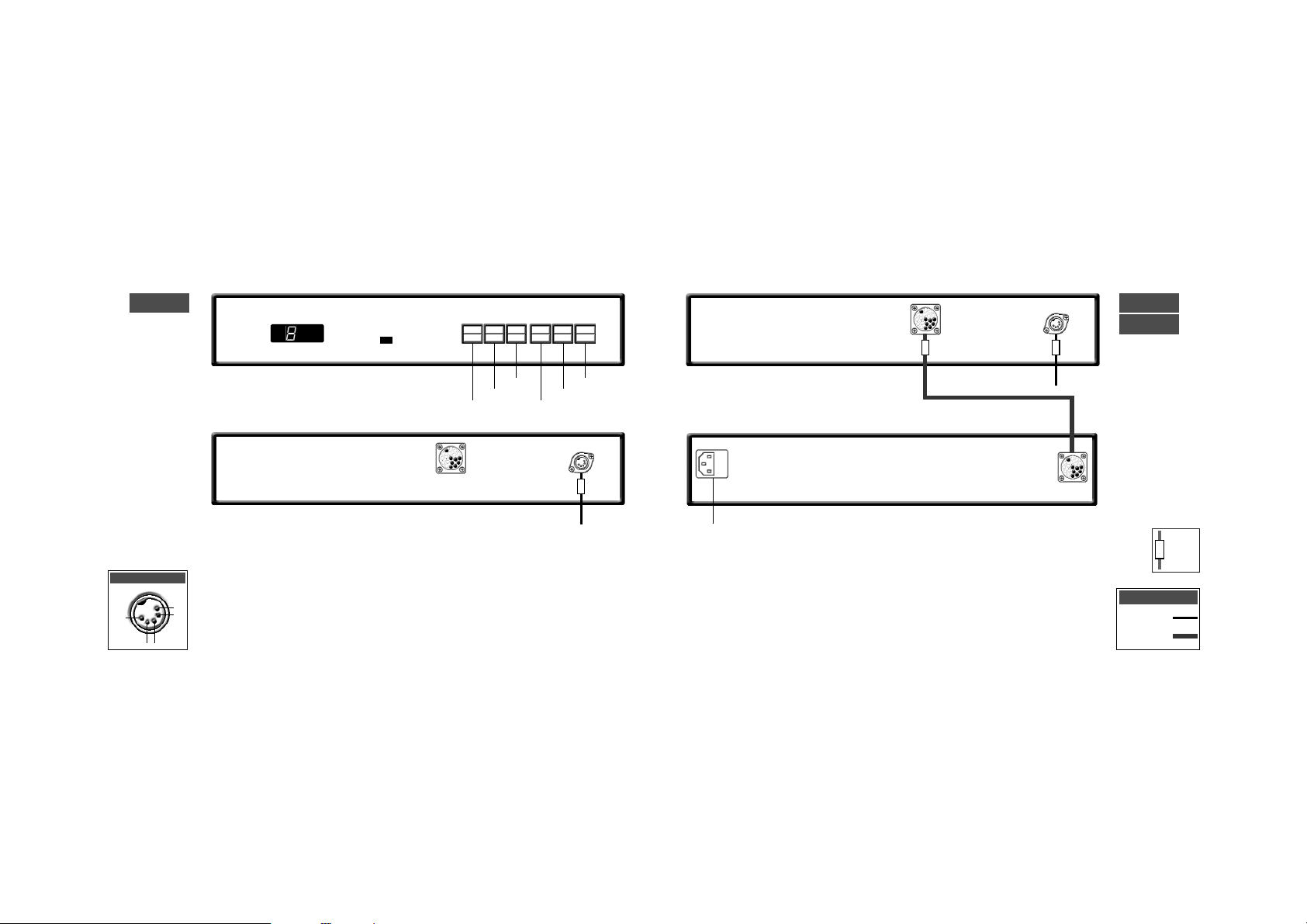
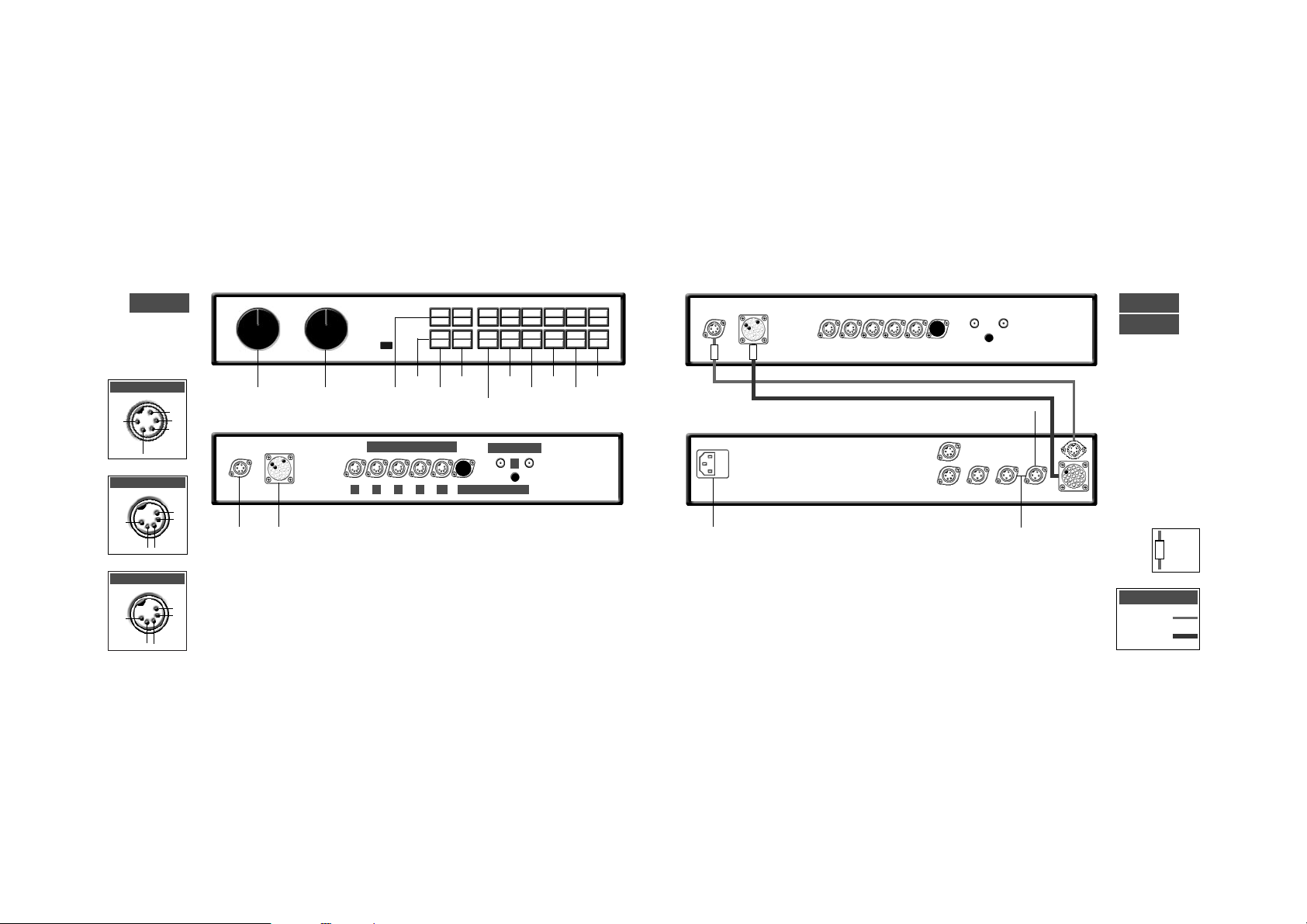
cds connection to xps power supply
cds
xps
cd players
cds
2
track
time
repeat
program
to preamplifier
mains input
to preamplifier
5-5 180˚ DIN
11-11 Burndy
Interconnects
display
previous
next
pause
stop
play
ch1
nc
nc
-ve
ch2
cds output
Page 4

5
cd players
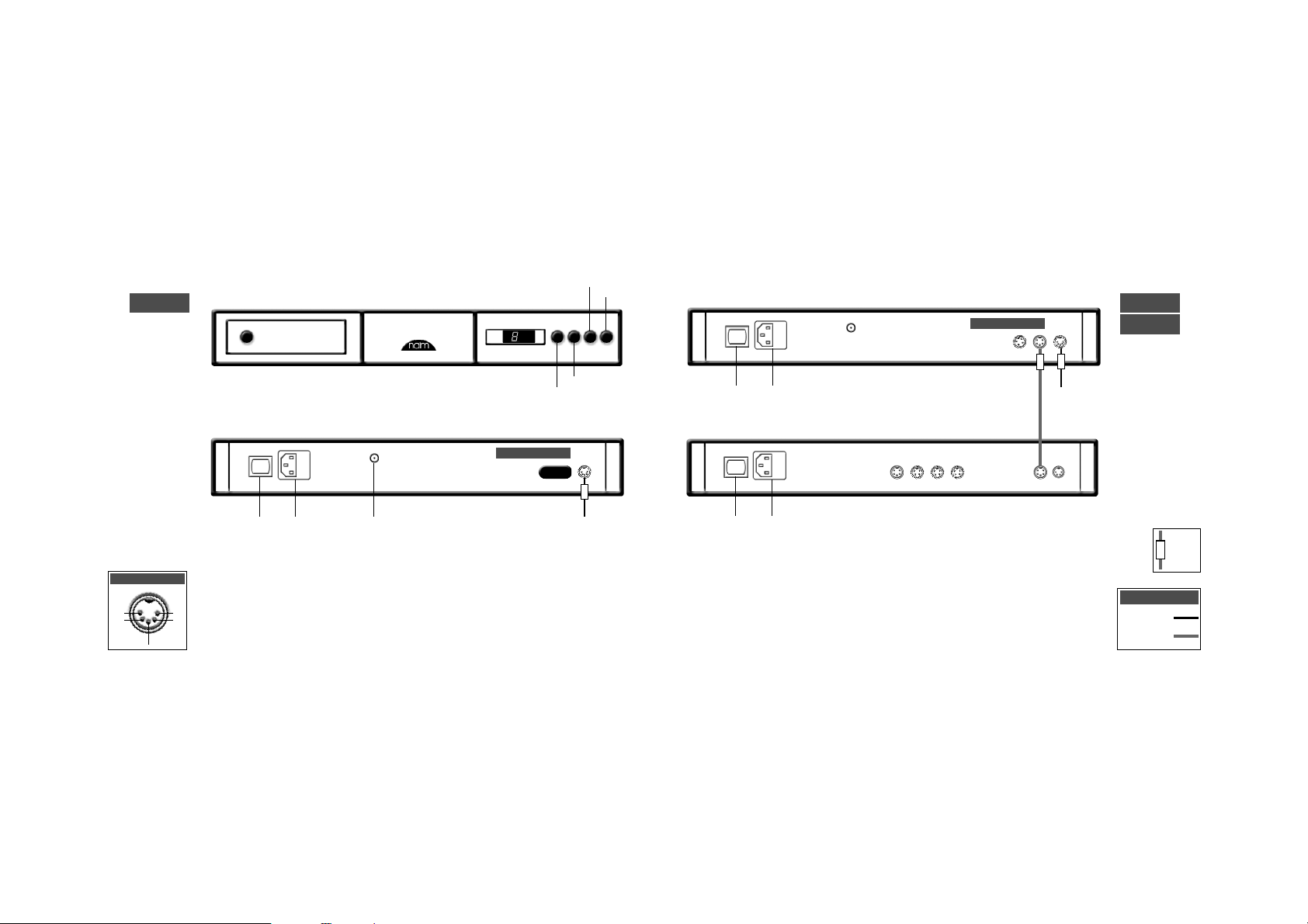
cdx connection to xps power supply
cdx
xps
cd players
cdx
4
pause
time
repeat
program
link plug fitted
to preamplifier
mains input
power switch
to preamplifier
cable
direction
marker
5-5 180˚ DIN
11-11 Burndy
Interconnects
mains input
note
Do not connect the cdx to mains power.
ch1
nc
nc
-ve
ch2
cdx output
previous
next
stop
play
Page 5
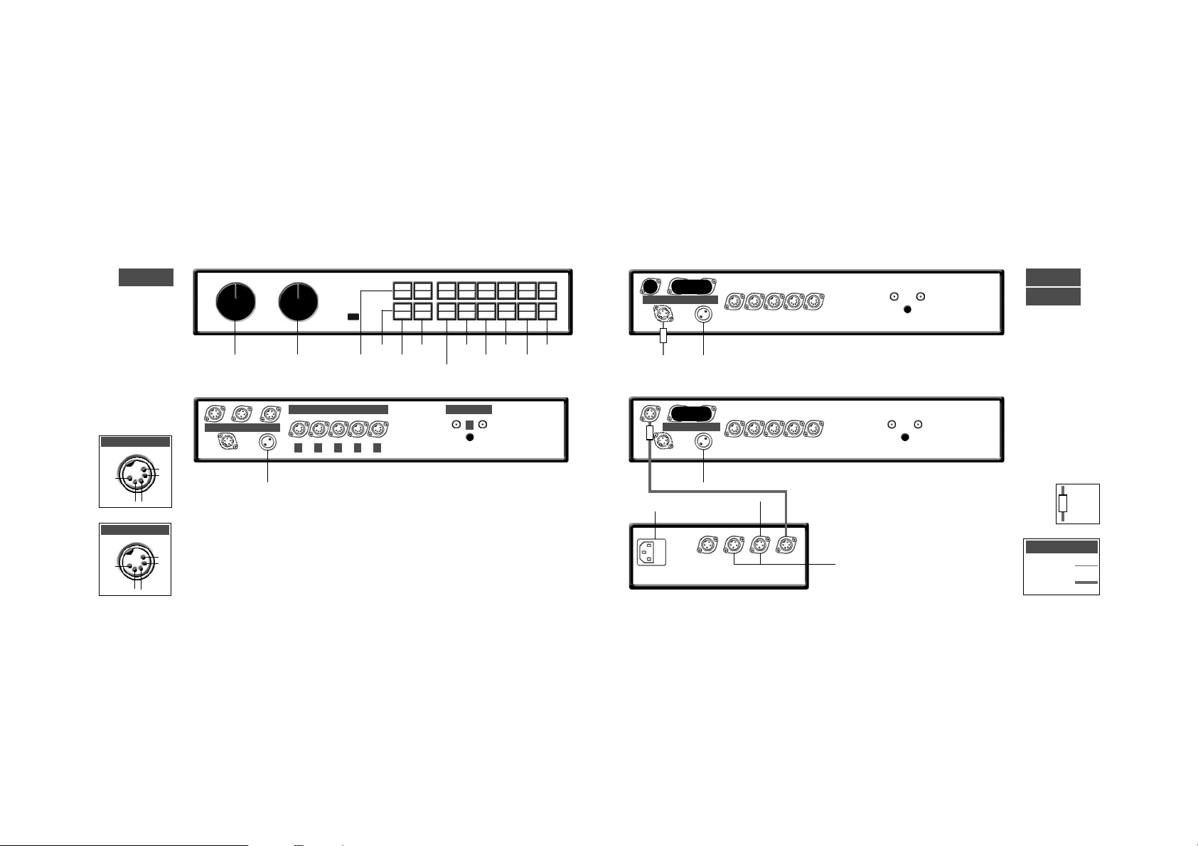
7
cd players
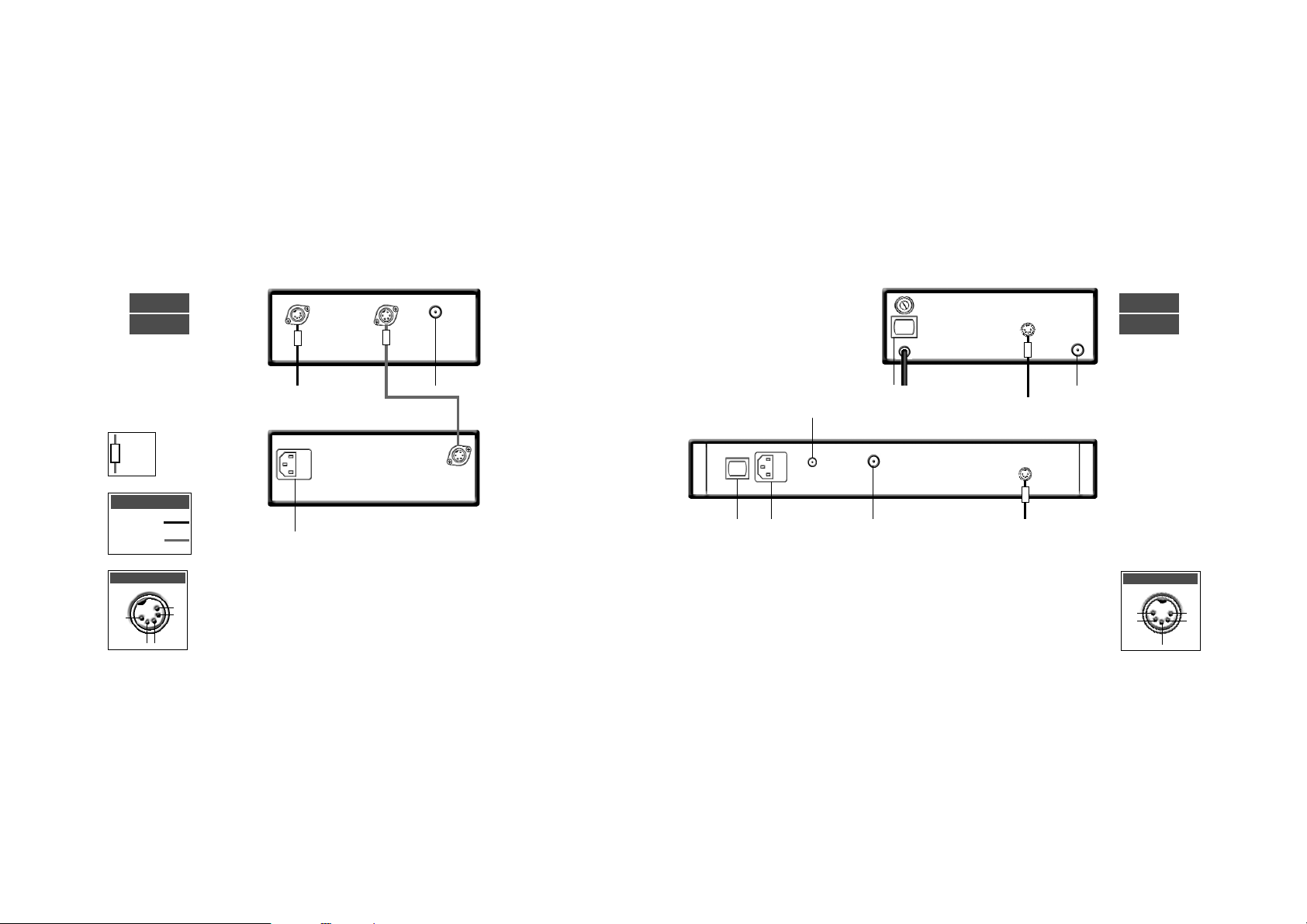
cd5 connection to flatcap 2 power supply
cd players
6
link plug fitted
to preamplifier
rc5 input
link plug removed
to preamplifier
ch1
nc
nc
-ve
ch2
cd5 output
cable
direction
marker
5-5 180˚ DIN
5-5 240˚ DIN
Interconnects
cd5
flatcap 2
cd5
previous
next
stop
play
note
cd5 players manufactured after April 2001 are fitted
with an RC5 control input. This input is designed to
accept external control signals for multi-room
applications. Contact your dealer for further
information on its use.
mains input
power switch
mains input
power switch
mains input
power switch
Page 6
9
tuners
tuners
napst
nat 01
8
ch1
nc
nc
-ve
ch2
nat 01 output
nat 01 connection to napst power supply
to preamplifier
75 ohm FM aerial
mains input
rc5 input
cable
direction
marker
5-5 180˚ DIN
5-5 240˚ DIN
Interconnects
ch1
nc
nc
-ve
ch2
nat 02/05 output
75 ohm FM aerial
to preamplifier
75 ohm FM aerial
to preamplifier
nat 05
nat 02
note
The RC5 input is designed to accept
external control signals for multi-room
applications. Contact your dealer for
further information on its use.
mains input
power switch
power switch
mains input
Page 7
to:
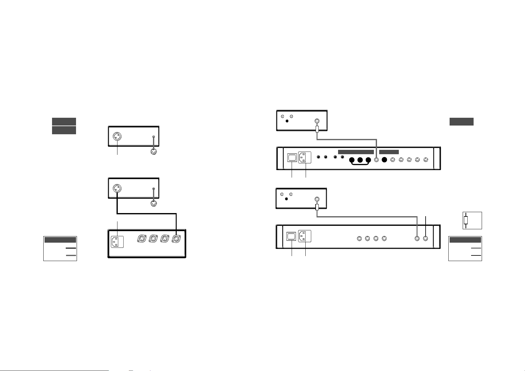
nac 52, nac 82, nac 102:
socket 4, 5 or 6.
nac 112, nait 5:
socket 3, 4 or 5.
11
phono stage
stageline connection to nait 5 or nac 112
stageline connection to flatcap 2
stageline
headphone amplifier
headline connection to napsc or hi-cap power supply.
headline
10
from napsc
to:
nac 52, nac 82, nac 102:
socket 4, 5 or 6.
nac 112, nait 5:
socket 3, 4 or 5.
all link plugs fitted
cover fitted
5-2 SLIC
Captive 5/180˚ DIN
Interconnects
cable
direction
marker
hi-cap
to preamp. 4
to 5 pin
interconnect
required
mains input
mains input
power switch
mains input
power switch
5-5 240˚DIN
4-5 DIN
Interconnects
Page 8
13
preamplifiers
nac 52 connection to supercap power supply
nac 52
supercap
preamplifiers
nac 52
12
6
5 4 3
2a 2b (blank fitted)
1
high level inputs
phono input
digital
power supply
audio power supply
ch1
nc
nc
-ve
ch2
inputs 3 & 2a
ch1
ch1
ch2
-ve
ch2
inputs 6, 5 & 4
input 2b
+ve
ch1
ch2
-ve
+ve
cable
direction
marker
5-5 240˚ DIN
16 -16 Burndy
Interconnects
1
inputs
mono
volume
balance
mute
2a/b
3
4
5
6
rec
source
to nap 140, 150 or 180 power amplifiers (4 pin DIN) or nap 250 power amplifier (4 DIN-XLR)
to nap 135 or nap 500 power amplifiers (4 pin to XLR)
mains input
Page 9
15
preamplifiers
nac 82 connection to nap 140, 150 and nap 180 power amplifiers
nac 82 connected to one hi-cap or flatcap 2
nac 82
hi-cap
preamplifiers
nac 82
14
6 5 4 3
2
1
high level inputs
outputs
phono input
napsc
link plugs fitted
napsc
to nap 140,150
& 180 power
amplifiers
link plug fitted
napsc
ch1
nc
nc
-ve
ch2
inputs 3 & 2
ch1
ch1
ch2
-ve
ch2
inputs 6, 5 & 4
note
The napsc power supply must
be connected to the nac 82 at
all times.
4-4 DIN to nap 140, 150 & 180
4 DIN-XLR to nap 250
4 DIN-XLR to
nap 135 & 500
cable
direction
marker
4-4 DIN
5-5 240˚ DIN
Interconnects
1
inputs
mono
volume
balance
mute
2
3
4
5
6
rec
source
mains input
Page 10
17
preamplifiers
nac 82 connection to supercap
nac 82
supercap
preamplifiers
nac 82 connection to two hi-caps or flatcaps
nac 82
hi-cap
16
napsc
4-4 DIN to nap 140, 150 & 180
4 DIN-XLR to nap 250
4 DIN-XLR to
nap 135 & 500
all link plugs removed
napsc
all link plugs removed
4-4 DIN to nap 140, 150 & 180
4 DIN-XLR to nap 250
4 DIN-XLR to nap 135 & 500
cable
direction
marker
5-5 240˚ DIN
Interconnects
cable
direction
marker
5-5 240˚ DIN
Interconnects
note
Sound quality will be severely impaired if power
supplies are mixed. A flatcap together with a hi-cap
for example. Similarly, both outputs of a Flatcap 2
should not be used simultanesously to power one
preamp.
mains input
mains input
mains input
do not use
do not use
Page 11

19
preamplifiers
nac 102 connection to hi-cap or flatcap
nac 102
hi-cap
preamplifiers
nac 102 connection to one power amplifier with internal power supply
nac 102
18
1b
high level inputs
outputs
phono input
6
5
4
3
2
1a
4-4 DIN to nap 140, 150 & 180
note
When connecting a hi-cap without an napsc, the
large link plug must be fitted (see previous page).
link plugs
fitted
volume
balance
inputs 3, 2 & 1a
inputs 6, 5 & 4
ch1
nc
nc
-ve
ch2
ch1
ch1
ch2
-ve
ch2
napsc
(optional)
link plugs removed
4-4 DIN to nap 140, 150 & 180
4 DIN-XLR to nap 250
4 DIN-XLR to
nap 135 & 500
cable
direction
marker
5-5 240˚ DIN
Interconnects
1
inputs
monitor
mute
2
3
4
5
6
mains input
Page 12

21
preamplifiers
nac 112 connection to flatcap 2
nac 112
preamplifiers
nac 112
20
link plug & cover fitted
cover fitted
monitor
mute
cd
tuner
tape
a/v
aux 1
aux 2
volume
4-4 DIN to nap 140, 150 & 180
aux 1
tape
a/v
tuner
aux 2
cd
note
The aux 2 input is provided with two sockets. The
left hand socket, fitted on delivery with a blanking
cover, is intended for use with a Stageline or Prefix
phono stage and incorporates an appropriate DC
power supply.
ch1
ch1
ch2
-ve
ch2
tape, a/v & aux 1
inputs
ch1
nc
nc
-ve
ch2
cd, tuner & aux 2
inputs
nac 112 connection to one power amplifier with internal power supply
to nap 140, 150,
180 & 250 power
amplifiers
to nap 135 & 500
power amplifiers
for cd5, headline or
stageline. Additional
interconnects
required.
cable
direction
marker
5-5 240˚ DIN
Interconnects
flatcap 2
mains input
power switch
Page 13

dig
out
2
23
a/v processor
av2 connection to nap v175
av2
nap v175
a/v processor
av2
22
V1 MUL
encoder
input mode
mains
input
rear
out
cen
out
sur
out
fr’t
out
sub
out
rc5
in
dig
out
1
dig
in
1
data
i/o
vs
1
i/o
rec
out
rec
out
ch1
left
an’g
in 3
dig
in
2
dig
opt
out
dig
opt
in 2
dig
opt
in 1
an’g
in 6
an’g
in 4
ch 2
right
an’g
in 2
(vip)
an’g
in 1
(vip)
power
switch
ch1
nc
ch2
-ve
rear, surround &
front outputs
centre output
cen
nc
(sub)
-ve
analogue in 3
ch1
ch1
front
out
ch2
-ve
ch2
analogue in 2
ch1
nc
nc
-ve
ch2
analogue in 1
ch1
nc
nc
-ve
ch2
analogue in V2 & V1 multi mode
V2 V1
cen
in
ch1
ch2
-ve
sub
in
ch1
ch1
ch2
-ve
ch2
rear
in
surr
in
front
in
mains
input
power
switch
- ++ -
- +
4-4 DIN
Interconnects
to nap 140, 150, 180 &
250 power amplifiers
to nap 140, 150, 180 &
250 power amplifiers
to preamp
Page 14

25
integrated amplifier
nait 5 connection to flatcap 2
nait 5
integrated amplifier
nait 5
24
link plugs/covers fitted
aux 1
tape
a/v
tuner
aux 2
out A
out B
in
cd
monitor
mute
cd
tuner
tape
a/v
aux 1
aux 2
volume
mains input
power switch
ch1
ch1
ch2
-ve
ch2
tape, a/v & aux 1
inputs
ch1
nc
nc
-ve
ch2
cd, tuner & aux 2
inputs
+V in +V in
ch1
-ve
ch2
signal out A
for cd5, headline or
stageline. Additional
interconnects
required.
flatcap 2
mains input
power switch
link plugs removed, cover fitted
mains input
power switch
cable
direction
marker
4-4 DIN
5-5 240˚ DIN
Interconnects
speakers
ch1, left
speakers
ch2, right
- ++ -
- ++ -
Page 15

27
integrated amplifier
nait 5 connection to flatcap 2 and nap150
nait 5
integrated amplifier
nait 5 connection to nap 150
nap 150
nait 5
26
link plug fitted
mains input
power switch
mains input
power switch
note
Do not connect the nait 5 to mains power.
cable
direction
marker
4-4 DIN
Interconnects
mains input
power switch
link plugs removed
flatcap 2
nap 150
cable
direction
marker
4-4 DIN
5-5 240˚ DIN
Interconnects
speakers
ch1, left
speakers
ch2, right
- ++ -
speakers
ch1, left
speakers
ch2, right
- ++ -
note
Do not connect the nait 5 to mains power.
Page 16

29
power amplifiers
nap 500 connection to na ps500 power supply
nap 135
power amplifiers
na ps500
nap 500
28
2
1
-venc
ch2
Socket 2
-vech1
nc
Socket 1
-venc
ch2
Socket 2
-vech1
nc
Socket 1
speakers
ch1, left
speakers
ch2, right
mains input
to preamp
power supply.
ch 1, left
to preamp
power supply.
ch 2, right
9-9 Burndy
Interconnects
mains input
to power supply
fan
2
1
fan
2
1
mains input
to power supply
speakers
ch1, left
speakers
ch2, right
- +
- +
- +
+ -
Page 17

31
power amplifiers
power amplifiers
nap 180
nap 150
nap 250
30
-ve
ch2
ch1
+ve
mains input
to power supply
mains input
to preamplifier
or power supply
to preamplifier
or power supply
speakers
ch1, left
speakers
ch2, right
-vech1
ch2
nap 250
nap 180
nap 140
mains
input
power
switch
to preamplifier
or power supply
nap 140
nap 6-50
-ve
ch2
+ve
ch1
mains
input
zone 1
speakers
ch 1, left
zone 2
speakers
ch 1, left
zone 1
speakers
ch 2, right
zone 2
speakers
ch 2, right
zone 3
speakers
ch 2, right
zone 3
speakers
ch 1, left
- + - + - +
- + - + - +
mains input
zone 1
trigger
zone 3
zone 2
speakers
ch1, left
speakers
ch2, right
speakers
ch1, left
speakers
ch2, right
- ++ -
- ++ -
- ++ -
speakers
ch1, left
speakers
ch2, right
- ++ -
mains
input
power
switch
to av
processor
speakers
ch1, left
speakers
centre
- ++ -
napv 175
nap 150
ch1
+ve
ch2
-ve
napv 175 Skt 2
ch1
nc
ch2
-ve
napv 175 Skt 1
centre
nc
nc
-ve
ch1
nc
ch2
-ve
nap 6-50
speakers
ch2, right
- +
2
1
Page 18

33
power supplies
power supplies
hi-cap
supercap
32
mains input
1
3
4
5
7
6
2
hi-cap
Socket 4
+ve
ch1
ch2
-ve
+ve
ch1
nc
-ve
ch2
hi-cap
Sockets 1, 2 & 3
ch1
nc
ch2
-ve
Sockets 2, 3, 4 & 6
supercap
Socket 1
+ve
ch1
ch2
-ve
+ve
supercap
Socket 2
+ve
nc
nc
-ve
+ve
ch1
nc
-ve
ch2
supercap
Sockets 3, 4, & 5
mains input
1 2 3 4
note
supercap socket 6 for nac 52 only
supercap socket 7 for nac 52 and snaxo only
mains input
power switch
1 2 3 4 5 6
flatcap 2
+ve +ve
ch1
-ve
ch2
Sockets 1 & 5
note
socket group 1, 2 3 & 4. and socket group 5 &
6 are entirely seperate.
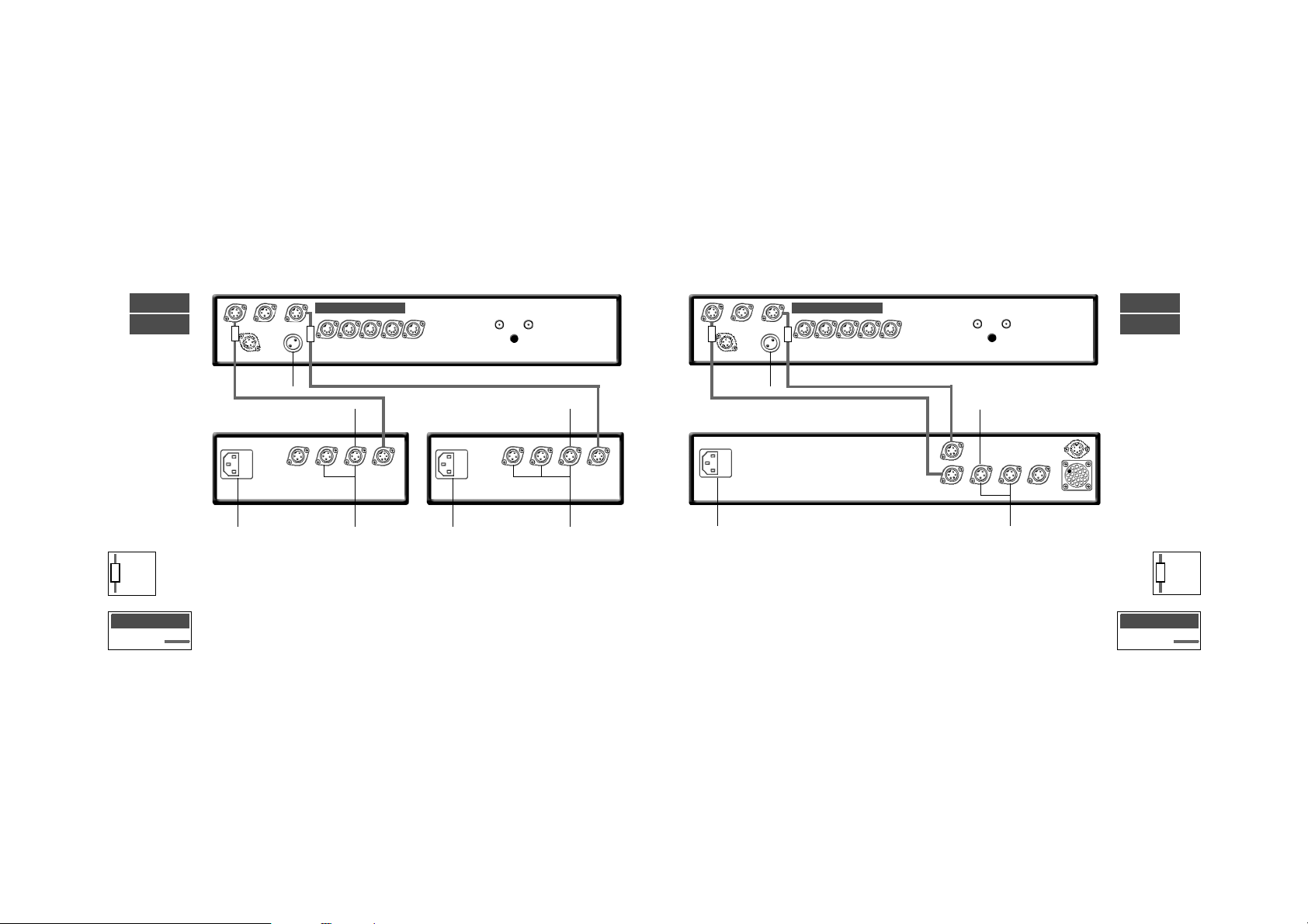
Page 19

35
power supplies
nac 52 connection to supercap with second supercap for snaxo
nac 52
supercap
supercap
power supplies
nac 52 connection to supercap with optional extra hi-cap for snaxo
supercap
hi-cap
nac 52
34
to snaxo
to snaxo
16 -16 Burndy
5-5 240˚ DIN
4-4 DIN
Interconnects
cable
direction
marker
16 -16 Burndy
5-5 240˚ DIN
4-4 DIN
Interconnects
cable
direction
marker
mains input
mains input
mains input
mains input
Page 20

37
power supplies
nac 82 connection to supercap with extra hi-cap for snaxo
nac 82
supercap
hi-cap
power supplies
nac 82 connection to two hi-caps with extra flatcap 2 for snaxo
36
nac 82
hi-cap
napsc
mains input
power switch
mains input
all link plugs removed
to snaxo
flatcap 2
cable
direction
marker
cable
direction
marker
4-4 DIN
5-5 240˚ DIN
Interconnects
4-4 DIN
5-5 240˚ DIN
Interconnects
for cd5, headline or
stageline. Additional
interconnects
required.
napsc
all link plugs removed
to snaxo
mains input
mains input
Page 21

39
power supplies
nac 112 connection to flatcap 2 with extra flatcap 2 for snaxo, cd5, stageline or headline
nac 112
flatcap 2
power supplies
nac 82 connection to supercap with extra supercap for snaxo
38
nac 82
supercap
supercap
napsc
all link plugs removed
to snaxo
16 -16 Burndy
5-5 240˚ DIN
4-4 DIN
Interconnects
cable
direction
marker
to snaxo
cover fitted
for cd5, headline or
stageline. Additional
interconnects
required.
cable
direction
marker
4-4 DIN
5-5 240˚ DIN
Interconnects
mains input
mains input
mains input
power switch
mains input
power switch
Page 22

41
active crossovers
snaxo connection to hi-cap from nac 52 and supercap
supercap
hi-cap
snaxo
active crossovers
snaxo 2-4
ixo 2
snaxo 3-6
40
1
2 - 4
5 - 7
1
2 - 3
4 - 5
1 2 3
o/p2
nc
o/p1
-ve
ixo sockets 1 & 2
ch1
nc
ch2
-ve
ixo socket 3
o/p1
nc
-ve
o/p2
3-6 sockets 5 - 7
o/p2
nc
-ve
o/p1
2-4 sockets 4 & 5
o/p1
nc
-ve
-ve
3-6 sockets 2 - 4
-ve
nc
-ve
o/p1
2-4 sockets 2 & 3
+ve
ch1
ch2
-ve
+ve
3-6/2-4 socket 1
mains input
power switch
link plug fitted
cable
direction
marker
4-4 DIN
5-5 240˚ DIN
Interconnects
to nac 52
level adjustment
note
connections for the snaxo 3-6 and snaxo 2-4
are the same.
mains input
mains input
Page 23

43
active crossovers
snaxo connection to hi-cap from nac 82, 102, 112 and hi-cap
hi-cap
snaxo
hi-cap
active crossovers
snaxo connection to supercap from nac 52 and supercap
supercap
supercap
snaxo
42
to nac 52
link plug removed
cable
direction
marker
4-4 DIN
17 -17 Burndy
Interconnects
to preamp
link plug fitted
note
If a nac 82 is powered by two hi-caps the
connections are the same (from 82 hi-cap
number one).
hi-caps earlier than serial number 105469
must be connected together via the second
set of sockets rather than the third - as
illustrated by the dotted connection cable.
cable
direction
marker
4-4 DIN
5-5 240˚ DIN
Interconnects
mains input
mains input
mains input
mains input
Page 24

45
active crossovers
supercap
supercap
snaxo
active crossovers
hi-cap
snaxo
supercap
44
to nac 82
link plug fitted
snaxo connection to hi-cap from nac 82 and supercap
cable
direction
marker
4-4 DIN
5-5 240˚ DIN
Interconnects
to nac 82
link plug removed
snaxo connection to supercap from nac 82 and supercap
cable
direction
marker
4-4 DIN
17 -17 Burndy
Interconnects
mains input
mains input
mains input
mains input
Page 25

47
active crossovers
nap 500
nap 500
active crossovers
snaxo 3-6 connection to three nap 500
snaxo 3-6
nap 500
46
ch1 bass green ch1 mid red
ch2 bass green
ch2 mid red
ch2 treble
red
ch1 treble
green
4 DIN/XLR Red
4 DIN/XLR Green
Interconnects
- +
+ -
- +
+ -
- +
+ -
Page 26

49
48
active crossovers
nap 500
active crossovers
sanxo 2-4 connection to two nap 500
snaxo 2-4
nap 500
ch1 bass green ch1 treble red
ch2 bass green
ch2 treble red
4 DIN/XLR Red
4 DIN/XLR Green
Interconnects
- +
+ -
- +
+ -
Page 27

51
active crossovers
nap 135
nap 135
nap 135
active crossovers
snaxo 3-6 connection to six nap 135
nap 135
nap 135
snaxo 3-6
nap 135
50
4 DIN/XLR Red
4 DIN/XLR Green
Interconnects
ch1 bass green
ch1 mid
red
ch2 mid
red
ch2 bass green
ch1 treble green
ch2 treble
red
- +
- +
- +
- +
- +
- +
mains input
mains input
mains input
mains input
mains input
mains input
Page 28

53
active crossovers
active crossovers
52
nap 135
nap 135
snaxo 2-4 connection to four nap 135
nap 135
nap 135
snaxo 2-4
4 DIN/XLR Red
4 DIN/XLR Green
Interconnects
ch1 treble red
ch1 bass green
ch2 bass green
ch2 treble red
- +
- +
- +
- +
mains input
mains input
mains input
mains input
Page 29

55
active crossovers
snaxo 2-4 connection to two nap 250
snaxo 2-4
nap 250
nap 250
active crossovers
snaxo 3-6 connection to three nap 250
54
nap 250
snaxo 3-6
nap 250
nap 250
4 DIN/XLR White
Interconnects
4 DIN/XLR White
Interconnects
ch1 bass
ch1 mid
ch2 bass
ch2 mid
ch1 treble
ch2 treble
ch1 bass
ch1 treble
ch2 bass
ch2 treble
mains input
mains input
mains input
mains input
- ++ -
- ++ -
- ++ -
- ++ -
- ++ -
- ++ - - ++ -
Page 30

57
active crossovers
ixo 2 connection to two nap 150
active crossovers
nac 112 connection to flatcap 2 and ixo 2
flatcap 2
ixo 2
nac 112
56
cover fitted
left
right
for cd5, headline or
stageline. Additional
interconnects
required.
cable
direction
marker
cable
direction
marker
4-4 DIN
5-5 240˚ DIN
Interconnects
ch1 bass
ch1 treble
ch2 bass
ch2 treble
ixo 2
nap 150
nap 150
4-4 DIN
Interconnects
power switch
mains input
mains input
power switch
power switch
mains input
mains input
power switch
mains input
power switch
- ++ -
- ++ -
Page 31

58
Naim Audio Southampton Road Salisbury England SP1 2LN
Tel: +44 (0)1722 332266 www.naim-audio.com
OWNCG
•
issue 2 •August 2001
 Loading...