

Page 1
U-800
UHF 800-Channel Wireless System
OWNER’S MANUAL
Page 2

CONTENTS
1. INTRODUCTION ................................................................................ 2
2. USING THIS MANUAL .......................................................................2
3. SYSTEM FEATURES ............................................................................3
4. QUICK USER CONTROLS GUIDE ........................................................ 4
5. SYSTEM OPERATION .........................................................................8
6. SELECTING GROUP/CHANNEL, IR PROGRAMMING
AND SIMULTANEOUS MULTICHANNEL OPERATION ........................14
7. CAUTIONS AND TROUBLESHOOTING ............................................. 17
8. MISCELLANEOUS TIPS .....................................................................18
9. SPECIFICATIONS .............................................................................19
10. FREQUENCY PLAN ........................................................................ 20
11. FREQUENCY LISTS ......................................................................... 21
12. OPTIONAL ACCESSORIES .............................................................22
13. SERVICE INFORMATION ................................................................ 22
14. ONE YEAR LIMITED WARRANTY ....................................................23
1. INTRODUCTION
Thank you for choosing the Nady U-800 wireless system, and congratulations on
your choice. The U-800 has the best performance and price value in professional
UHF wireless, offering clear-channel, frequency-agile operation on the UHF band for
interference-free performance in any application or locale. The U-800 delivers 800
user-selectable, frequency synthesized channels in the US frequency band 470MHz490MHz. The Nady U-800 offers built-in Autoscan for quick and convenient open
channel selection and set up of one system, or many wireless systems at the same
location for simultaneous multichannel operation. The U-800 features proprietary
companding and low-noise circuitry for an industry-best 120dB dynamic range, and
the clearest, most natural sound available in wireless today
2. USING THIS MANUAL
This booklet provides instructions for the operation of the U-800 and includes a
description of features, a quick user controls guide, a step-by-step guide to operations
for each unit, system specifications, a troubleshooting guide, miscellaneous tips, and
servicing information.
2
Page 3

3. SYSTEM FEATURES
U-800 RECEIVER
• Unsurpassed state-of-the-art PLL UHF performance with 120dB dynamic range and long-
range operation, up to 500 ft. (line-of-sight)
• 800 user-selectable UHF frequencies, with one-touch Autoscan open-channel automatic
selection
• ASC™ (Auto-Sync Channels) download feature sends selected channel information to
transmitter via IR sender for easy frequency synchronization
• Sophisticated IF ltering for optimal simultaneous operation of up to 14 systems in the
same location
• To facilitate multiple, simultaneous systems operation setup, the 800 selectable channels are
available from 10 optimized factory pre-set groups of up to 14 compatible channels and 5
additional user-select groups, all offering 800 channels each. All groups retain in memory the
previously selected channels for that group for easy setup subsequently in the same location.
• DigiTRU Diversity™ for maximum range and dropout protection
• 120dB Dynamic Range — the quietest and best sounding UHF wireless available at any price
• Tone Squelch™ for locking out potential interference, and special circuitry for noiseless
transmitter ON/OFF switching
• Dual front-panel permanently attached swivel antennas
• Front LCD panel displays A/B diversity, Group/Channel with frequency, ASC™ transfer
status, RF/AF level, Mute (squelch) level, and push On/Off power switch
• Back panel with Balanced XLR xed Mic Level and adjustable Unbalanced ¼” jacks, audio
Line Level outputs with volume control and DC input jack
• Half-rack receiver design with unique snap-out, side panel locking tabs for single receiver
or dual receivers (side-by-side) optional rack mounting
• Externally powered with included DC adapter (120VAC/22VDC/400 mA)
• Choice of transmitters: UH-800 handheld Mic or UB-800 bodypack—lavalier (LT),
Headmic™ (HM), or instrument (GT)
UH-800 HANDHELD MIC TRANSMITTER
• Sleek metal housing with internal antenna for optimum aesthetics and durable long life
• Features the Nady DM -10D unidirectional neodymium dynamic cartridge for optimum
true sound, maximum feedback rejection and minimal handling noise
• 800 easily selectable channels via IR Sync download for easy synchronization with
receiver’s selected channel
• Easy accessible audio level adjustment for optimum sound
• Power On/Off and Audio Mute switch allows convenient audio muting with the
transmitter “ON”
• Status LED indicators for unit “ON” (green) and for low-battery alert “ON” (red)
• Convenient, economical operation with two AA alkaline or rechargeable NiMH batteries
UB-800 BODYPACK INSTRUMENT TRANSMITTER
• Choice of transmitters: UB-800 bodypack—lavalier (LT), Headmic™ (HM), or instrument (GT)
• 800 easily selectable channels via IR Sync download for easy synchronization with receiver’s
selected channel
• Easy accessible input level adjustment for optimum sound
• Power On/Off and Audio Mute switch allows convenient audio muting with the transmitter “ON”
• Bicolor LED status indicator for unit “ON” and for low battery alert “ON”
• Convenient, economical operation with two AAA Alkaline or rechargeable NiMH batteries
• Ultra-compact housing, removable antenna and unique locking 3.5mm mini plug connector
for mic or instrument cable
3
Page 4
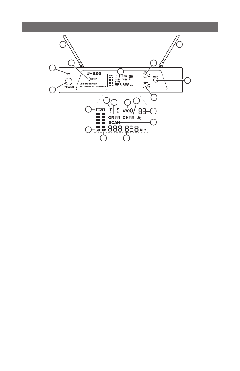
4. QUICK USER CONTROLS GUIDE
3
U-800 RECEIVER: FRONT VIEW
2
1
4
5
9
11
10
6
7
8
15
12
16
17
13
14
3
18
1. POWER BUTTON BUTTON push in to power receiver ON or OFF
2. POWER LED LED indicates receiver is turned ON
3. DUAL ANTENNAS permanently mounted., rotate to 45° as shown for optimal
reception
4. ASC/IR infrared LED window for sync receiver and transmitter. Transmits LED
Infrared signal for linking the receiver to the transmitter for frequency downloads
5. LCD DISPLAY shows receiver current status
6. MUTE ICON indicates audio muted
7. AF INDICATOR displays received Audio level
8. RF INDICATOR displays received radio signal level
9. A/B INDICATORS indicates diversity A or B antenna reception when
transmitter is on
10. IR INDICATOR INDICATOR indicates IR ASC™ receiver-to-transmitter channel
sync is in progress
11. GROUP indicates group number
12. CHANNEL indicates channel number
13. MUTE LEVEL shows muting level
14. SCAN ICON indicates scanning is in progress
15. FREQUENCY indicates frequency in MHz
16. UP BUTTON BUTTON to change the receiver MUTE level up, GRP/CH up by
one step at a time or activate ASC™ sync in IR menu
17. DOWN BUTTON to change the receiver MUTE level down, GRP/CH down by
one step at a time
18. MENU BUTTON repeatedly press the button to advance to the next menu, or press
once to start the Auto Scan/IR/Sync function or to manually select GR/CH. Use
MENU BUTTON for easy set up with ONE TOUCH PROGRAMMING. Start the
IR link download of the receiver’s selected channel to the transmitter. Position the
transmitter IR RECEPTOR WINDOW (37,44) 6-12” away from the receiver
IR window, press the MENU button once and wait five second, the receiver will
4
Page 5
SCAN and IR automatically for the open channel. The IR INDICATOR will flash
19
20
21
22
for 2 seconds. If the IR data download is successful, the receiver’s RF (8) and
A/B INDICATORS (9) will also be on, indicating channel transfer is complete.
See also section “6. Selecting Group/Channel, IR Programming and
Simultaneous Multichannel Operation”
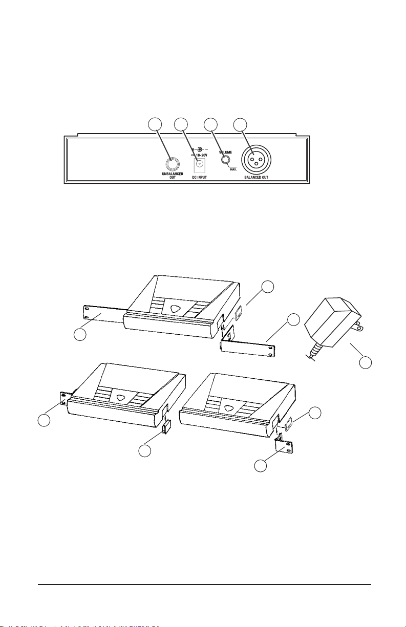
U-800 RECEIVER: BACK VIEW
19. UNBALANCED LINE OUT ¼” JACK Line level audio output, adjustable
with Volume control
20. DC INPUT JACK For connecting external AC/DC adapter to power receiver
(DC22VDC/400mA)
21. VOLUME CONTROL Selects desired output volume level for the Unbalanced
Line Out
22. BALANCED MIC OUT XLR JACK Audio output at xed MIC level
24
25
25
27
26
27
24
23. DC POWER SUPPLY ADAPTER 120VAC/22VDC/400mA
24. SIDE MOUNT CLIP removes to leave space for optional rack ears
25. ERM-12 SINGLE RACK KIT optional rack ears for single receiver rack
mounting
26. EJC-3 JOINING CLIP supplied with ERM-22 kit for joining two receivers
side-by-side for dual rack mounting
27. ERM-22 DUAL RACK KIT optional rack ears for rack mounting two
receivers side by side
23
5
Page 6

UH-800 HANDHELD TRANSMITTER: FRONT AND BOTTOM VIEW
28. MIC BALL/ ANTENNA windscreen also functions as antenna, so for best
operating range do not handle this antenna during use
29. BATTERY COVER unscrew CCW to open battery tube to insert batteries
30. AUDIO INPUT LEVEL normally set at middle position, turn knob with small
flat head screw driver for optimum sound
31. TWO AA BATTERIES operating from two AA batteries
32. BATTERY COMPARTMENT holds two AA alkaline or NiMH batteries,
observe correct polarity
33. POWER ON LED indicates the transmitter ON (green)
34. LOW BATTERY LED indicates the batteries are weak (red)
35. RF POWER slide the switch to power the transmitter ON or OFF
36. AUDIO MUTE slide the switch to ON or OFF to mute audio with transmitter
powered on
37. IR RECEPTOR SENSOR/WINDOW infrared LED sensor for linking the
transmitter to the receiver during IR selected frequency downloads
29
28
31
33
34
30
35
OFF
6
ON
36
37
32
Page 7

UB-800 BODYPACK TRANSMITTER: FRONT VIEW
38. ANTENNA Removable antenna—should be attached during operation
39. INPUT JACK Locking 3.5mm mini-jack for connecting audio input cord from
lapel mic (LT), Headmic™ (LT/HM), or instrument (GT) cable
40. AUDIO MUTE slide the switch to ON or OFF to mute audio with transmitter
powered on
41. BI-COLOR BATTERY STATUS LED indicates green for strong usable battery
and red for low battery needing replacement
42. POWER ON/OFF slide switch to power receiver ON or OFF
43. INPUT VOLUME LEVEL adjusts input (LT/HM) audio level for optimal sound
44. IR RECEPTOR SENSOR infrared LED sensor for linking the transmitter to the
receiver during IR selected-frequency download
45. BATTERY COMPARTMENT holds two AAA alkaline or NiMH batteries
46. LATCHING BATTERY DOOR open fully to insert batteries
47. BELT CLIP on back of unit
48. INSTRUMENT CORD GT cable—connects instrument’s audio output to TX
input jack
49. HEADMIC™ Headworn microphone (choice of models)—connects to
transmitter input jack
50. LAVALIER MIC Lavalier (lapel) microphone (choice of models)—connects to
transmitter input jack
48
43
39
46
40 41
44
45
42
38
49
50
47
7
Page 8
5. SYSTEM OPERATION
U-800 RECEIVER
Button Function
The POWER ON Button (1) is used to power receiver ON or OFF. When the
power button is pressed, the POWER LED (2) and the white backlight on the LCD
DISPLAY (5) will light up indicating the receiver is ready. Press the Power button
again to turn off the receiver. The power LED and the backlight on the LCD will be off
indicating the receiver is off. At power-off the U-800 receiver will store the last settings entered and re-display them at power-on. It can be reprogrammed to any new
Group/Channel, or Mute level. The default factory setting is Group 11, Channel 01
and Mute 0 on the first LCD menu screen.
The UP BUTTON (16) is pressed one step at a time to SCAN, IR or to increase
GROUP, CHANNEL, MUTE by one level each time
The DOWN BUTTON (17) is pressed one step at a time to decrease GROUP,
CHANNEL, MUTE by one level each time
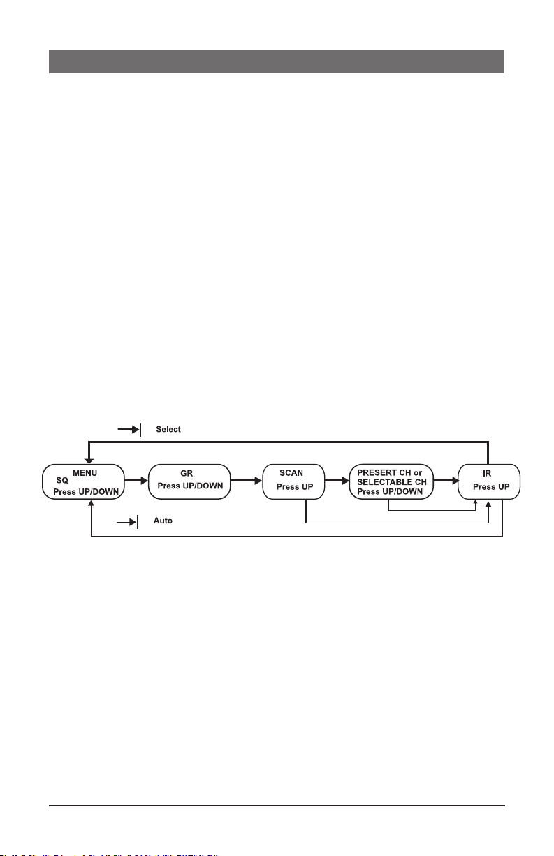
The MENU BUTTON (18) is pressed one step at a time for Auto Scan Frequency
or to Automatic GR/CH ASC™ Sync, or if pressed repeatedly the LCD DISPLAY (5)
menu will cycle through the following screens.v
During manual programming, press the MENU BUTTON (18) to confirm the selec-
tion and advance to the next menu before the Auto Programming Function takes over
after 5 sec.
Rack Mounting the Receiver
There are 2 options available for rack mounting the U-800 receiver: singly or side
by-side with another U-800 receiver.
a. Single mounting: Remove the receiver SIDE MOUNT CLIP (24) from each side of
the receiver (as shown) and slide in the optional ERM-12 RACK EARS (25).
b. Side-by-side double mounting: After removing the SIDE MOUNT CLIPS (24) from
both U-800 receivers join the two receivers with the EJC-3 JOINING CLIP (26)
and attach the ERM-22 RACK EARS (27) as shown.
(Note: Do not mount the receiver in a rack directly above an amplier or other source
of high heat — this could degrade the performance of the U-800. Always ensure
adequate airflow and heat dissipation in any rack configuration.)
8
Page 9

Powering the Receiver
Plug the AC/DC ADAPTER (23) provided into the DC INPUT JACK (20)
on the back of the receiver. Then plug the power supply into an AC outlet. (Note:
Any 22V DC source with 400mA capability can also be used.) Press the POWER
SWITCH (1) once to turn on the receiver. The POWER ON LED (2) and the LCD
DISPLAY (5) will now light and the receiver is operational.
Adjusting Antennas
The U-800 has two permanently attached, exible elbow ANTENNAS (3) for diver-
sity reception. Unfold and rotate these antennas to operate the receiver. The optimal
positions of the antennas are flared 45° out from the receiver sides and 90° from each
other. For maximum range, it is always best to maintain a line-of-sight (no obstructions)
between the receiver antennas and the transmitter at all times whenever possible.
Adjusting the Mute Level/ RF Squelch
The MUTE LEVEL/RF SQUELCH (13) can be changed anytime during the main
screen display to quiet the receiver in high noise environment condition. The control
ranges are from level 0 to level 5. The level should be adjusted to a lower number
for the minimum RF squelch setting at which the RF INDICATOR (8) will remain on
while your transmitter is in normal use, up to the maximum operating range anticipated in use for your application. However, in areas of high RF activity, the squelch
control may need to be adjusted to a higher number. If the transmitter is off and the
receiver’s signal RF INDICATOR (8) or the diversity A or B INDICATOR (9) flickers
or stays on continuously, the squelch should be adjusted to a higher number to stop
the flickering. Be careful not to select too high a number setting as this may reduce
the operating range to below what is needed. A range walk test will help in select-
ing the proper level. If the range is not critical, note that a higher level (maximum
squelch) setting will also yield a quieter mute function, which might be desired in
certain applications. The squelch level is factory preset at maximum sensitivity and
operating range (i.e. level 0 for minimum squelch level—maximum usable range).
Note: For easier intuitive operation, the MIN and MAX indications for this control
refer to the minimum and maximum operating range settings, not to the actual mute
levels selected, which are the opposite as per above.
Keyboard/Buttons Lock Function
Use keyboard/Buttons Lock Function to lock or unlock the receiver controls, preventing accidental adjustment during use: You can push and hold MENU BUTTON (18),
then push UP BUTTON (16) to lock; push and hold MENU BUTTON (18), then
push UP BUTTON (16) again to unlock. The Keyboard/Buttons must be unlocked
before you can make a selection: AUTO SCAN, Group/Channel or MUTE levels.
9
Page 10

Audio Level and Peak LED Indicator
1/4” Plug
The U-800 receiver has a 5 bar AF LCD (7) display that typically shows a few bars
SYSTEM OPERATION
indicating normal level audio signal from the transmitter. Occasional flickering of
the fifth AF LCD (peak level) on loud inputs to the transmitter is normal. If the AF LCD
lights up full bars continuously decrease the input audio level to the transmitter or
overload distortion may result.
Connecting the Audio Output
The U-800 receiver has two type of outputs available, an adjustable level ¼”
UNBALANCED LINE OUT (19) and a xed level MIC out BALANCED MIC
OUT XLR JACK (22). The ¼” unbalanced line out is controlled by the VOLUME
CONTROL (21).
For unbalanced line output connection, plug an audio cable with a ¼” mono
(Tip/Sleeve) plug into the Unbalanced Line Out jack and plug the other end into your
mixing board or amplier. Adjusting the Volume control will increase or decrease the
audio level at the ¼” Unbalanced Line Out only.
(Note: When using the UB-800 instrument transmitter system, connect the
Unbalanced Line Out directly to your instrument amp or preamp. At maximum
receiver volume setting, the system output is approximately +4dB higher than a direct
cord-to-amp connection.)
For balanced Output connection, plug an audio cable with an XLR connector into the
Balanced Mic Out XLR Jack socket and plug the other end into your mixing board or
amplifier and control the audio levels from there.
Both the ¼” Unbalanced Line Out and the XLR Balanced Mic Out can be used at the
same time to connect to your mixing board, effect, or amplier. Please follow below
drawing for the audio cable/connector wiring.
Pin 2: +
Pin 2: +
Pin 1: Ground
Tip = signal (+)
Sleeve = ground
SLEEVE
TIP
Your U-800 receiver is now operational and ready to use. Proceed to the following
instructions for the UH-800 handheld microphone transmitter or UB-800 bodypack
transmitter included with your system.
Note: As when making any connection, make sure the amplifier or mixing board
volume is at the minimum level before plugging in the receiver to avoid possible
sound system damage.
Note: : Only one transmitter can be used with one receiver. It is not possible to use
two transmitters on the same frequency and mix the output of these transmitters into
F-XLR
one wireless receiver.
10
Page 11

Programming the U-800 to the Selected Group/Channel (frequency)
The Receiver must be programmed for a Group/Channel (frequency) first then auto-
matic synchronization using the IR ASC™ Sync function to the transmitter. For system
set up procedures, see next section “6. Selecting Group/Channel, IR Pro-
gramming and Simultaneous Multichannel Operation”
UH-800 HANDHELD MICROPHONE TRANSMITTER (HT)
Setting up the UH-800 Transmitter
The UH-800 requires two AA alkaline or NiMH batteries to operate (do not mix
types). Installing batteries by unscrewing counterclockwise the BATTERY COVER
(29) and slide down, exposing the BATTERY COMPACTMENT (32). Insert two
fresh AA BATTERIES (31), observing the correct polarity as marked, and screw the
cover back on to the microphone. Make sure the cover is screwed clockwise completely. Fresh alkaline batteries can last up to 10 hours in use, but in order to ensure
optimum performance, it is recommended that you replace the batteries after every
6-8 hours of use.
Powering the UH-800 Transmitter On/Off
Turn on the UH-800 by sliding the AUDIO SWITCH (36) to the OFF position first.
Then slide the POWER SWITCH (35) to the ON position. The POWER ON LED
(33) will stay on, indicating that the transmitter is now on. The BATTERY LED (34)
will stay off, indicating usable battery strength. In the case of a dead or low battery,
the low battery LED will light red continuously, indicating that the batteries should be
replaced with fresh ones.
To preserve battery life, turn the transmitter off when not in use. To turn the transmitter
off, slide the RF POWER (35) switch to the OFF position. The POWER ON LED
(33) is not lit up, indicating the unit is off. The MUTE ICON (6) on the receiver
should be on, muting the audio out.
At power off the transmitter will store the last settings entered and re-display them at
the next power on. The default factory setting is Group 11, Channel 01.
For optimum performance, an AUDIO INPUT LEVEL (30) is provided. Adjust the
gain by turning the control with a small screwdriver. It is recommended that the level
be set at about 1/2 maximum. Experiment and set for maximum possible gain without audible distortion on the high level peaks. (Note: Turning down the gain too much
can compromise the signal-to-noise and it is not recommended.)
The microphone is now ready to use. The diversity A/B INDICATORS (9) on the
U-800 receiver should now be on, indicating a received signal from the transmitter.
When ready to speak, slide the AUDIO MUTE (36) to the ON position. The MUTE
ICON (6) on receiver should be off. Adjust the volume of the receiver as per the Au-
dio Output Microphone Connection section of the above U-800 receiver instructions.
11
Page 12

Note: : The windscreen of the UH-800 functions as a built-in antenna. For proper
operation, never remove the windscreen during use, or exchange with another type.
For optimum range maintain line-of-sight between the transmitter and the receiver
whenever possible. Holding the microphone tightly, bridging across the windscreen
and Mic tube, will also lessen range. Hold by the Mic tube housing only for optimum
operation.
Note: Observe care in selecting P.A. volume, transmitter location and speaker
placement so that acoustic feedback (howling or screeching) will be avoided.
Operating the UH-800 Handheld Transmitter
The RF POWER (35) and the AUDIO MUTE (36) switches have two positions
for power ON/OFF and audio mute ON/OFF respectively. During normal operation
with the unit powered on standby, slide the RF POWER (35) switch to the ON position. You will feel a slight click indicating the ON position is selected. The receiver’s
RF Indicator (8) and diversity A/B INDICATOR (9) should now be on, indicating a received RF signal from the transmitter. When ready to transmit audio, slide the
AUDIO MUTE (36) to ON to un-mute. To mute, slide the switch to OFF again. Ad-
just the volume of the receiver per the previous section, Connecting the Audio Output.
Note: Avoid acoustic feedback (howling or screeching) by taking care in selecting
PA volume, transmitter location and speaker placement.
Programming the UB-800 to the Selected Group/Channel (frequency)
The transmitter must be programmed to the same frequency as selected for the re-
ceiver via automatic synchronization using the IR ASC™ Sync function. It can not be
programmed on the transmitter itself. See in next section “6. Selecting Group/
Channel, IR Programming and Simultaneous Multichannel Operation”.
UB-800 BODYPACK MICROPHONE TRANSMITTER (LT, HM OR GT)
Setting up the UB-800 Transmitter
The UH-800 requires two AAA alkaline or NiMH batteries to operate (do not mix
types). To install the batteries, lift the LATCHING BATTERY DOOR (46) and open
up, exposing the BATTERY COMPARTMENT (45). Insert two fresh AAA batteries
according to the polarity indicated on the transmitter body. Close the battery cover
back onto the microphone, making sure it is secure. Fresh alkaline batteries can
provide up to 8 hours of operation, but in order to ensure optimal performance it is
recommended that the batteries be replaced after 4-6 hours of use or as indicated
necessary by the BATTERY STATUS LED (41) lit RED.
Powering the UB-800 Transmitter On/Off
Turn on the UB-800 by sliding the AUDIO MUTE (40) to the OFF position first.
Then slide the POWER ON/OFF (42) to the ON position. The BATTERY STA-
TUS LED (41) will stay on GREEN and the transmitter is now on, indicating usable
battery strength. In the case of a dead or low battery, the LEDs will not go on at all or
the BATTERY STATUS LED (41) will stay on RED continuously, indicating that the
batteries should be replaced with fresh ones.
12
Page 13

To preserve battery life, turn the transmitter off when not in use. To turn the transmitter off, slide the POWER ON/OFF (42) switch to the OFF position. The BATTERY
STATUS LED (41) is not lit up, indicating the unit is off. The MUTE ICON (6) on
receiver should be on, muting the audio out.
At power off the transmitter will store the last settings entered and re-display them at
the next power on. The default factory setting is Group 11, Channel 01.
For optimum performance, an INPUT VOLUME LEVEL (43) is provided (for LT/
HM input mode operation only). Adjust the gain by turning the control with a small
screwdriver. It is recommended that the level be set at about 1/2 maximum. Experiment and set for maximum possible gain without audible distortion on the high level
peaks. (Note: Turning down the gain too much can compromise the signal-to-noise
and it is not recommended.)
The microphone is now ready to use. The diversity A or B INDICATORS (9) on the
U-800 receiver should now be lit, indicating a received signal from the transmitter.
When ready to speak, slide the AUDIO MUTE ON/OFF SWITCH (40) to the
ON position. The MUTE ICON (6) on receiver should be off. Adjust the volume of
the receiver as per the Audio Output Microphone Connection section of the above
U-800 receiver instructions.
Note: The transmitter has a removable ANTENNA (38). For best operating range, it
should be attached (screwed on tightly counterclockwise, or exchange with another type.).
For best transmitting power during use, make sure it is not blocked. For optimum range
maintain line-of-sight (no obstructions) between the transmitter and the receiver whenever
possible. A walk test before use will determine the operating range in your application.
Note: Observe care in selecting P.A. volume, transmitter location and speaker
placement so that acoustic feedback (howling or screeching) will be avoided.
Operating the UB-800 Transmitter
The POWER ON/OFF SWITCH (42) and the AUDIO MUTE ON/OFF
SWITCH (41) switches have two positions for power ON/OFF and audio mute
ON/Standby respectively. During normal operation with the unit powered on
standby, slide the RF POWER (35) switch to the ON position. You will feel a slight
click indicating the ON position is selected. The receiver’s RF INDICATOR (8) and
diversity A/B INDICATOR (9) should now be on, indicating a received RF signal
from the transmitter. When ready to transmit audio, slide the AUDIO MUTE (36)
to ON to un-mute. To mute, slide the switch to OFF again. Adjust the volume of the
receiver per the previous section, Connecting the Audio Output.
Note: Avoid acoustic feedback (howling or screeching) by taking care in selecting
PA volume, transmitter location and speaker placement.
13
Page 14

Connecting Input Audio Source
Lapel/Head Mic Uses (UB-800 LT/HM)
The mini 3.5mm locking INPUT JACK (39) is for connecting the audio input from a
lavaliere/lapel Mic (LT), a Head Mic™ (HM), or an instrument (GT) cable, depending
on which transmitter version is being used. Secure the connection to the cable by tightening the cable mini plug’s outer ring counterclockwise. When ready to play, slide the
AUDIO MUTE ON/OFF SWITCH (40) to the ON position to un-mute the audio.
Adjust the INPUT VOLUME LEVEL (43) on the transmitter for suitable level.
Instrument Use (UB-800 GT)
Secure the connection of the GT (instrument) cable by tightening the mini plug outer
ring counterclockwise onto the 3.5mm locking INPUT JACK (39). When ready
to play, slide the AUDIO MUTE ON/OFF SWITCH (40) to the ON position to
un-mute the audio. Adjust the volume on the receiver for one-to-one unity gain with
a hardwired cord or select up to an added 4-5dB boost by adjusting the receiver
volume to maximum for normal use with guitars and bass guitars.
Note: The audio level should be adjusted on the instrument as when using a hardwired cord.
Programming the UB-800 to the Selected Group/Channel (frequency)
The transmitter must be programmed to the same frequency as selected for the receiver
via automatic synchronization using the IR ASC™ Sync function. It cannot be programmed on the transmitter itself. See next section “6. Selecting Group/Channel,
IR Programming and Simultaneous Multichannel Operation”.
6. SELECTING GROUP/CHANNEL, IR PROGRAMMING
AND SIMULTANEOUS MULTICHANNEL OPERATION
Note: Note: The transmitter should be turned ON and ready for the IR communications with the receiver IR receptor for the following process.
Note: If no button is pressed within the five seconds period during a selection, the
program is terminated and the process needs to be repeated.
Note: For normal operation, the transmitter should have the same channel as displayed on the receiver.
Choosing Group/Channel for the System
The receiver offers a choice of 15 groups: 10 that are Factory PRESET (Group 11
to 1A) and 5 that are User SELECTABLE (Group 1B to 1F). If the Factory PRESET
Group mode is chosen, only a limited numbers of channels are available in these
groups. For most convenient setup, each of these groups offers from 3 to 14 channels
(depending on group selected) to choose from that are factory preset for simultaneous
multichannel operation compatibility and are retained in memory after the receiver
is powered off. For the User SELECTABLE Group 1B-1F mode, a letter “U” will lit up
on the LCD DISPLAY (5) instead of the CHANNEL (12) number as in the Factory
PRESET Groups. Each User SELECTABLE Group has 800 channels to choose from
either by manually selecting a channel or using the Auto-Scan in 1MHz segment
increments at a time within the frequency band and they are retained in memory
14
Page 15

after receiver is powered off. This facilitates easy setup by enabling quick selection of
stored channels for any group, i.e, selecting any group will automatically display the
last channel selected for that group. See section “11. U-800 Frequency Lists”
for available channels in each group. The previous group and channel used is stored
in memory automatically when receiver and transmitter are turned off after operation.
Selecting a different group on the receiver in subsequent use will display a different channel as previously selected for that group, however, the transmitter will need
again to be sync’ed to that new frequency to complete the system setup for operation.
Receiver ASC/IR Sync GR/CH (Frequency)
If different frequencies than previously stored in both the receiver and transmitter memories are needed, there are three ways to program the receiver and then
sync the selected Group/Channel to the transmitter: One-Touch Automatic ASC™/
Auto Sync receiver to transmitter, manual SCAN for Group/Channel, or manual
select Group/Channel from the Factory Preset or User Selectable channel. Place the
transmitter’s IR RECEPTOR SENSOR WINDOW (37, 44) 6-12” away from the
receiver’s IR WINDOW (4) before starting the following steps.
• For One-Touch channel Autoscan and Automatic ASC™/Auto Sync from the
receiver to the transmitter, press the MENU BUTTON (18) once, wait for about
5 seconds, the receiver will start process automatically with no further user action
required. A running bar in a clockwise direction on the LCD DISPLAY (5) shows
the scanning process which normally takes about two seconds. When it finds an
interference-free channel, the receiver stores the channel for use, and it will begin
ASC™ sync IR download of the selected channel to the transmitter automatically.
• To manually scan the selected Group/Channel, press the MENU BUTTON (18) twice
for AUTOSCAN menu, press UP BUTTON (16) once and it will start scanning. A
running bar in a clockwise direction shows the scanning process, which normally takes
about 2 seconds. When it finds an interference-free channel, it will display and store the
frequency/channel for use. It can be rescanned again for a new frequency by pressing
the UP button or pressing the MENU BUTTON twice to IR MENU (IR icon will lit up for IR
function), then pressing UP BUTTON to start IR programming.
• To manually select Group/Channel press the MENU BUTTON (18) once for
GROUP (11) selection for Factory PRESET Group 11 to 1A mode or User SELECTABLE Group 1B to 1F mode. Use the UP/DOWN Buttons to change the group. After selecting a group, press the MENU BUTTON twice for channel selection menu.
Use the UP/DOWN Buttons to change the channels (frequencies) that are available in each group. [Note: for Group11 to 1A, the CH (12) display will indicate
the channel number chosen, and for Group 1B to 1F only the letter “U” and the
frequency chosen will be displayed. See section “11. U-800 Frequency Lists”
for available channels in each group]. After finishing channel selection, press the
MENU BUTTON once or wait a few seconds for IR MENU, and then press UP BUTTON to start IR programming.
This completes the GP/CH (frequency) programming. The next section outlines the
procedure for sync’ing the receiver’s programmed channel to the transmitter.
15
Page 16

Receiver/Transmitter ASC™ IR Sync Manual Programming
To manually program the pre-selected Group/Channel (frequency) from the receiver
to the transmitter, place the transmitter’s IR RECEPTOR SENSOR WINDOW (37,
44) 6-12” away from the receiver’s IR WINDOW (4). Press the MENU BUTTON
(18) four times to the IR Screen Display and then press the UP BUTTON (16) to
start IR programming. The flashing IR INDICATOR (10) icon indicates IR transmission is in progress. When the synchronization is completed successfully (usually in
less than 2 seconds), the RF INDICATOR (8) and the diversity A or B INDICA-
TOR (9) on the receiver will display, indicating that the IR linking is completed. The
LCD DISPLAY SCREEN (5) will show the selected channel. If the UP button is not
pressed during the two seconds of active data transfer, the IR INDICATOR (10) will
not flash, the LCD Display will revert to the main menu, the receiver will not link to the
transmitter, and the transmitter’s previously programmed channel remains unchanged.
Instructions for Setup of Simultaneous Multichannel Operation
This U-800 receiver is capable of finding an open channel with its autoscan capability. This built-in feature is a quick, convenient way to set up many wireless systems at
the same location for simultaneous multichannel operation.
If you are using multiple transmitters at the same location, set up the first transmitter and
leave it ON and keep 10 feet away from the receivers and 1 foot away from transmitter
to transmitter. This avoids possible duplicate selection of the same channel as already
selected for the first receiver. Then start the autoscan function on the second receiver.
Repeat this procedure for all receiver/transmitters to be used in your system. Finally
with all the transmitters ON, perform a range walk test in the location these systems will
be used in to check for potential crosstalk interference in this application.
If you are not satisfied with any of the channels scanned, repeat the autoscan procedure for that receiver again anytime for finding another free channel.
This process can be simplified if you select channels within Factory SELECTED Groups
11 to1A, as the channels within those groups are mutually compatible (unless there is
outside interference on any of the selected frequencies). If there is any such interference in your location, select as many channels as you can using these 10 groups and
then select additional open channels as needed (depending on number of systems to
be operated simultaneously) from Groups 1B to 1F. As noted above all these groups
will retain in memory the previously selected channels for that group for easy setup
subsequently in that same location.
16
Page 17

7. CAUTIONS AND TROUBLESHOOTING
Feedback
Avoid acoustic feedback (howling or screeching) by taking care in selecting PA
volume, transmitter location and speaker placement.
Please also note the pickup pattern characteristics of the microphone selected.
Unidirectional microphones are more resistant to feedback. However, they pick up
sound sources best that are directly in front of the microphone. Also, mics that are
farther from the sound source (such as a handheld) require more acoustic gain and
thus are also more prone to feedback than close-source mics.
No or Low Audio
If you are not getting audio through the system, carefully re-check all setups.
Especially note that the receiver and transmitter must be set to operate on the same
RF channel. Also confirm that the transmitter’s AUDIO MUTE (36, 40) is not in the
OFF position. The receiver’s UNBALANCED LINE OUT (19) is adjustable so make
sure the VOLUME CONTROL (21) is set properly.
RF Interference and Finding Open Channels
The FCC mandates the following information be provided to all end users of this
equipment:
Consumer Alert
Most users do not need a license to operate this wireless microphone system.
Nevertheless, operating this microphone system without a license is subject to certain
restrictions: the system may not cause harmful interference; it must operate at a low
power level (not in excess of 50mW); and it has no protection from interference
received from any other device. Purchasers should also be aware that the FCC is
currently evaluating use of wireless microphone systems, and these rules are subject
to change.
For more information, call the FCC at 1-888-CALL-FCC (TTY: 1-888-TELL-FCC)
or visit www.fcc.gov/cgb/consumerfacts/wirelessmic_factsheet.html.
If you encounter slight receiving interference when the transmitter is far from the
receiver (from other than an operating TV station on the same frequency), it can
often be overcome by adjusting the receiver‘s MUTE LEVEL/SQUELCH (13)—see
Adjusting the Mute Level / RFSquelch.
If receiving interference on a selected channel with the transmitter off, or if you encounter interferences in operating multiple U-800 systems simultaneously at the same
location see: “6. Selecting Group/Channel, IR Programming and Simultaneous Multichannel Operation” for proper procedures for reprogramming
system(s) for open channels.
17
Page 18

8. MISCELLANEOUS TIPS
• The receiver antennas should be kept away from any metal surfaces whenever
possible as they can reflect away or shield the incoming RF signal.
• If the receiver’s volume control is set too high, it may overdrive the input of the
attached audio mixer, causing distortion. Conversely, if the output is set too low, the
overall signal-to-noise ratio of the system may be reduced, causing noticeable hiss.
If such noise occurs, adjust the output level of the receiver so that highest sound
pressure level going into the microphone transmitter causes no input overload in
the mixer, but permits the mixer level control to operate in the normal range (not
too high and not too low). This provides the optimal signal-to-noise for the entire
system.
• Before inserting the batteries, ensure that they are inserted with the correct polarity.
• Before operation, conrm that the receiver and associated transmitter are tuned to
the same frequency group and channel number.
• After making a receiver channel change, ensure that the corresponding change is
also made on the matching transmitter.
• Use only new alkaline or fully recharged NiMH batteries. Do not use “general
purpose” carbon batteries. When batteries are weak, replace all the batteries at the
same time. Do not mix new and old batteries.
• Position the receiver so that it has the least possible obstructions between it and the
transmitter. Line-of-sight is best!
• During operation, the transmitter and the receiver should be as close as possible for
optimum results but never closer than 3 ft. (1 m) as that may overload the receiver’s
input circuitry and cause noises.
• If rack mounting the receiver, keep away from heat sources such as amps by
allowing enough space between them for adequate ventilation.
• For the best operation, the receiver should be placed at least 3 ft. (1 m) above the
ground and 3 ft. (1 m) away from a wall or metal surface. The transmitter should
also be at least 3 ft. (1 m) from the receiver. Keep antennas away from noise
sources such as motors, automobiles, neon lights, signal processors, computers, as
well as large metal objects.
• A receiver cannot receive signals from two or more transmitters simultaneously.
• Turn the transmitter off when it is not in use. For longest life, remove the batteries if
the unit is not to be used for a long period as the transmitters draw a tiny residual
current to maintain the programmed settings, even when turned off. Also, since
batteries installed for a long time can sometimes corrode and/or leak, causing
damage, it is generally recommended that batteries be removed whenever the
transmitters are not being used.
• When using the bodypack for instrument use: Scratchy noises can sometimes occur
when an electric guitar with dirty pots or connections is used with a wireless system.
Therefore, the supplied capacitor provides first-order filtering of the RF signal from
the cord into the guitar and eliminates virtually all scratchy noises. Should your
equipment still produce scratchy noise, we suggest these steps to eliminate problems:
1) Make sure all guitar volume and tone pots are clean and all contacts are
solid. This is very important.
2) Solder a 47pF capacitor across the pot to ground terminal of the guitar’s
volume and tone pots to provide extra ltering.
18
Page 19

9. SPECIFICATIONS
U-800 OVERALL SYSTEM PERFORMANCE
Operating Frequency Range 470MHz–510MHz, two Bands
Freq. Synthesized (800 channels switchable) 25kHz/step
PLL system frequency stability <0.005%
Frequency Response 50Hz-18kHz +/-3dB
Dynamic Range 120dB
Harmonic Distortion <0.5%
Modulation FM (F3E) +/-50kHz normal, +/-100kHz max
Operating Range 150-250 feet typical, 500+feet max line-of-sight
U-800 RECEIVER
Receiver System Dual conversion Super Heterodyne with Digi-True
Diversity (dual antennas with optimum reception
selected)
Selectivity 60dB, normal +/-75kHz offset
Image Rejection -70dB, minimum
Sensitivity -107dBm, normal
Spurious Rejection 65dB, normal
Mute /Squelch Adjustable (-65dBm to -95dBm), Tone Squelch
40kHz
Controls Power ON/OFF push switch, VOLUME line level
pot, MENU, UP/DOWN buttons
LCD Display MUTE, AF/RF bars, A/B diversity, IR, GR/CH, MUTE
Level, SCAN, Frequency
LED indicator Power on
Audio Outputs LINE OUT UNBALANCED: adjustable line audio
output
MIC OUT BALANCED Fixed Mic level audio output
Output Impedance Unbalanced: 1k Ω and Balanced: for 600 Ω loads
Power Requirement 22VDC/0.4A
Antennas Dual permanently attached swivel antennas
Dimensions 8.1”W x 7.5”D x 1.75”H (20.7cm x 19cm x 4.4cm)
Weight 1lbs (454g)
Housing Construction ABS Plastic
UH-800 HANDHELD TRANSMITTER
RF Output Power +17dBm Max, +14dBm (25mW typical)
Harmonic/Spurious Emission -50dBc normal
Impedance 3.0 k Ω
Controls Power and Audio ON/OFF switches, Input Level
LED Display Power ON (GREEN), Low Battery ON (RED)
Antenna Type Integral
Battery Type 2 x AA alkaline batteries operation
Battery Life 8-10 hours typical
Dimensions 9”L x 2”D (22.86cm x 5.08cm)
Weight (w/o batteries) 11.6oz (329g)
Housing Construction Metal
19
Page 20

UB-800 BODYPACK TRANSMITTER
RF Output Power +17dBm Max, +14dBm (25mW typical)
Harmonic/Spurious Emission -50dBc normal
Input Impedance 4.7k Ω (Lavalier); 500 k Ω (Instrument)
Controls Power and Audio ON/OFF switches, Input Level
Input Connector Locking 3.5mm mini-jack
LED Display Bi-Color - Power ON (GREEN) and Low Battery ON
(RED)
Antenna Type External Removable
Battery Type 2 x AAA alkaline or NiMH
Battery Life 6-8 Hours typical, alkaline
Dimensions 3.25”W x 2.18”D x 1”H (8.25cm x 5.53cm x
2.54cm)
Weight (w/o batteries) 3.9 oz (111g)
Housing Construction ABS Plastic
Specications subject to change at any time without prior notice for purposes of
product improvement
10. FREQUENCY PLAN
800 Channels/25 KHz per step
Band 1: 470.000MHz–489.975MHz
Band 2: 490.000MHz–509.975 MHz
20
Page 21

11. U-800 FREQUENCY LISTS
Band 1: U-800 Frequency Listing Groups from 11 to 1A (470.000MHz-489.975MHz)
FAC TOR Y P RESE T C HAN NELS USE R S ELE CTA BLE CHA NNE LS
G
rou p 1 1 G rou p 1 2 Grou p 1 3 Gro up 1 4 Group 15 G roup 16 Grou p 17 Grou p 1 8 Gro up 1 9 Gr oup 1A
CH 1 470.325 470.025 470.050 470.125 470.725 471.425 471.300 477.300 483.300 488.100 CH 1 470.000
CH 2 470.725 470.625 470.925 470.425 475.825 471.725 471.750 477.750 483.750 489.450 CH 2 470.025
CH 3 471.225 471.425 472.125 475.325 476.425 478.025 472.350 478.350 484.350 489.750 CH 3 470.050
CH 4 472.025 472.425 473.625
CH 5 473.025 474.025 476.025
CH 6 474.425 476.025 479.025
CH 7 475.125 478.825 483.225
CH 8 476.325 483.025 489.525
CH 9 476.625 486.025
CH 10 479.125 489.225
CH 11 482.125
CH 12 484.125
CH 13 488.325
CH 14 489.425
473.100 479.350 485.100
474.300 480.300 486.300
475.800 481.800 487.800
Band 1: U-800 Frequency Listing Channels for each Group from 1B to 1F
(470.000MHz-489.975MHz)
USE R S ELE CTA BLE CHA NNE LS
CHS 1 51 101 151 201 251 301 351 401 451 501 551 601 651 701 751
1 470.000 471.250 472.500 473.750 475.000 476.250 477.500 478.750 480.000 481.250 482.500 483.750 485.000 486.250 487.500 488.750
2 470.025 471.275 472.525 473.775 475.025 476.275 477.525 478.775 480.025 481.275 482.525 483.775 485.025 486.275 487.525 488.775
3 470.050 471.300 472.550 473.800 475.050 476.300 477.550 478.800 480.050 481.300 482.550 483.800 485.050 486.300 487.550 488.800
4 470.075 471.325 472.575 473.825 475.075 476.325 477.575 478.825 480.075 481.325 482.575 483.825 485.075 486.325 487.575 488.825
5 470.100 471.350 472.600 473.850 475.100 476.350 477.600 478.850 480.100 481.350 482.600 483.850 485.100 486.350 487.600 488.850
6 470.125 471.375 472.625 473.875 475.125 476.375 477.625 478.875 480.125 481.375 482.625 483.875 485.125 486.375 487.625 488.875
7 470.150 471.400 472.650 473.900 475.150 476.400 477.650 478.900 480.150 481.400 482.650 483.900 485.150 486.400 487.650 488.900
8 470.175 471.425 472.675 473.925 475.175 476.425 477.675 478.925 480.175 481.425 482.675 483.925 485.175 486.425 487.675 488.925
9 470.200 471.450 472.700 473.950 475.200 476.450 477.700 478.950 480.200 481.450 482.700 483.950 485.200 486.450 487.700 488.950
10 470.225 471.475 472.725 473.975 475.225 476.475 477.725 478.975 480.225 481.475 482.725 483.975 485.225 486.475 487.725 488.975
11 470.250 471.500 472.750 474.000 475.250 476.500 477.750 479.000 480.250 481.500 482.750 484.000 485.250 486.500 487.750 489.000
12 470.275 471.525 472.775 474.025 475.275 476.525 477.775 479.025 480.275 481.525 482.775 484.025 485.275 486.525 487.775 489.025
13 470.300 471.550 472.800 474.050 475.300 476.550 477.800 479.050 480.300 481.550 482.800 484.050 485.300 486.550 487.800 489.050
14 470.325 471.575 472.825 474.075 475.325 476.575 477.825 479.075 480.325 481.575 482.825 484.075 485.325 486.575 487.825 489.075
15 470.350 471.600 472.850 474.100 475.350 476.600 477.850 479.100 480.350 481.600 482.850 484.100 485.350 486.600 487.850 489.100
16 470.375 471.625 472.875 474.125 475.375 476.625 477.875 479.125 480.375 481.625 482.875 484.125 485.375 486.625 487.875 489.125
17 470.400 471.650 472.900 474.150 475.400 476.650 477.900 479.150 480.400 481.650 482.900 484.150 485.400 486.650 487.900 489.150
18 470.425 471.675 472.925 474.175 475.425 476.675 477.925 479.175 480.425 481.675 482.925 484.175 485.425 486.675 487.925 489.175
19 470.450 471.700 472.950 474.200 475.450 476.700 477.950 479.200 480.450 481.700 482.950 484.200 485.450 486.700 487.950 489.200
20 470.475 471.725 472.975 474.225 475.475 476.725 477.975 479.225 480.475 481.725 482.975 484.225 485.475 486.725 487.975 489.225
21 470.500 471.750 473.000 474.250 475.500 476.750 478.000 479.250 480.500 481.750 483.000 484.250 485.500 486.750 488.000 489.250
22 470.525 471.775 473.025 474.275 475.525 476.775 478.025 479.275 480.525 481.775 483.025 484.275 485.525 486.775 488.025 489.275
23 470.550 471.800 473.050 474.300 475.550 476.800 478.050 479.300 480.550 481.800 483.050 484.300 485.550 486.800 488.050 489.300
24 470.575 471.825 473.075 474.325 475.575 476.825 478.075 479.325 480.575 481.825 483.075 484.325 485.575 486.825 488.075 489.325
25 470.600 471.850 473.100 474.350 475.600 476.850 478.100 479.350 480.600 481.850 483.100 484.350 485.600 486.850 488.100 489.350
26 470.625 471.875 473.125 474.375 475.625 476.875 478.125 479.375 480.625 481.875 483.125 484.375 485.625 486.875 488.125 489.375
27 470.650 471.900 473.150 474.400 475.650 476.900 478.150 479.400 480.650 481.900 483.150 484.400 485.650 486.900 488.150 489.400
28 470.675 471.925 473.175 474.425 475.675 476.925 478.175 479.425 480.675 481.925 483.175 484.425 485.675 486.925 488.175 489.425
29 470.700 471.950 473.200 474.450 475.700 476.950 478.200 479.450 480.700 481.950 483.200 484.450 485.700 486.950 488.200 489.450
30 470.725 471.975 473.225 474.475 475.725 476.975 478.225 479.475 480.725 481.975 483.225 484.475 485.725 486.975 488.225 489.475
31 470.750 472.000 473.250 474.500 475.750 477.000 478.250 479.500 480.750 482.000 483.250 484.500 485.750 487.000 488.250 489.500
32 470.775 472.025 473.275 474.525 475.775 477.025 478.275 479.525 480.775 482.025 483.275 484.525 485.775 487.025 488.275 489.525
33 470.800 472.050 473.300 474.550 475.800 477.050 478.300 479.550 480.800 482.050 483.300 484.550 485.800 487.050 488.300 489.550
34 470.825 472.075 473.325 474.575 475.825 477.075 478.325 479.575 480.825 482.075 483.325 484.575 485.825 487.075 488.325 489.575
35 470.850 472.100 473.350 474.600 475.850 477.100 478.350 479.600 480.850 482.100 483.350 484.600 485.850 487.100 488.350 489.600
36 470.875 472.125 473.375 474.625 475.875 477.125 478.375 479.625 480.875 482.125 483.375 484.625 485.875 487.125 488.375 489.625
37 470.900 472.150 473.400 474.650 475.900 477.150 478.400 479.650 480.900 482.150 483.400 484.650 485.900 487.150 488.400 489.650
38 470.925 472.175 473.425 474.675 475.925 477.175 478.425 479.675 480.925 482.175 483.425 484.675 485.925 487.175 488.425 489.675
39 470.950 472.200 473.450 474.700 475.950 477.200 478.450 479.700 480.950 482.200 483.450 484.700 485.950 487.200 488.450 489.700
40 470.975 472.225 473.475 474.725 475.975 477.225 478.475 479.725 480.975 482.225 483.475 484.725 485.975 487.225 488.475 489.725
41 471.000 472.250 473.500 474.750 476.000 477.250 478.500 479.750 481.000 482.250 483.500 484.750 486.000 487.250 488.500 489.750
42 471.025 472.275 473.525 474.775 476.025 477.275 478.525 479.775 481.025 482.275 483.525 484.775 486.025 487.275 488.525 489.775
43 471.050 472.300 473.550 474.800 476.050 477.300 478.550 479.800 481.050 482.300 483.550 484.800 486.050 487.300 488.550 489.800
44 471.075 472.325 473.575 474.825 476.075 477.325 478.575 479.825 481.075 482.325 483.575 484.825 486.075 487.325 488.575 489.825
45 471.100 472.350 473.600 474.850 476.100 477.350 478.600 479.850 481.100 482.350 483.600 484.850 486.100 487.350 488.600 489.850
46 471.125 472.375 473.625 474.875 476.125 477.375 478.625 479.875 481.125 482.375 483.625 484.875 486.125 487.375 488.625 489.875
47 471.150 472.400 473.650 474.900 476.150 477.400 478.650 479.900 481.150 482.400 483.650 484.900 486.150 487.400 488.650 489.900
48 471.175 472.425 473.675 474.925 476.175 477.425 478.675 479.925 481.175 482.425 483.675 484.925 486.175 487.425 488.675 489.925
49 471.200 472.450 473.700 474.950 476.200 477.450 478.700 479.950 481.200 482.450 483.700 484.950 486.200 487.450 488.700 489.950
50 471.225 472.475 473.725 474.975 476.225 477.475 478.725 479.975 481.225 482.475 483.725 484.975 486.225 487.475 488.725 489.975
Gro ups 1B -1F
: :
: :
: :
: :
: EVERY 25KHz
: :
: :
: :
C
H 7 98 489.925
C
H 7 99 489.950
C
H 8 00 489.975
Band 2: contact Nady Systems for frequency plan
21
Page 22

12. OPTIONAL ACCESSORIES
ERM-12 Single rack mount kit for one U-800 receiver
ERM-22 Dual rackmount kit for two U-800 receivers, includes EJC-3 joining clip
13. SERVICE INFORMATION
In the U.S. If you are experiencing operational problems with your system,
please refer to the Support page at www.nady.com for assistance. Should your
wireless system require service, please contact the Nady Service Department at
(510) 652-2411 for a Return Authorization (R/A) Number and service quote (if out
of warranty). Make sure the R/A Number is clearly marked on the outside of the
package that you are returning.
If your unit is out of warranty, please enclose a cashier’s check or money order (or
pay by credit card) per instructions by the Nady Service Department. Ship your unit
prepaid to: Nady Systems, Service Dept, 6701 Shellmound Street, Emeryville, CA
94608. Include a brief description of the problem you are experiencing. For service
of a unit under warranty, please follow the instructions in the following section.
Outside the U.S. For service or warranty matters please contact the Nady
distributor in your country through the dealer/store from which you purchased this
product.
Do not attempt to service this unit yourself as it can be dangerous
and will also void the warranty.
22
Page 23

14. ONE YEAR LIMITED WARRANTY
Nady Systems, Inc. warrants to the original consumer purchaser that the unit is free from any defects
in material or workmanship for a period of one year from the date of original retail purchase. If any
such defect is discovered within the warranty period, Nady Systems, Inc. will repair or replace the unit
free of charge, subject to verication of the defect or malfunction upon return to Nady Systems. Please
do not return your Nady product to the store where it was purchased as Nady Systems handles your
warranty service directly. Communication with our Service Department is the most efficient means of
servicing your unit and we are dedicated to keeping you a satisfied customer.
To the extent permitted by law, any applicable implied warranties, including warranties of
merchantability and fitness are hereby limited to one year from the date of purchase. Consequential
or incidental damages resulting from a breach of any applicable express or implied warranties are
hereby excluded. This warranty is in lieu of all other agreements and warranties, general or special,
express or implied and no representative or person including a Nady dealer, agent, or employee is
authorized to assume for us any other liability in connection with the sale or use of this Nady Systems’
product.
Whereas some states do not allow limitations on how long implied warranties last, and do not allow
exclusion of incidental or consequential damages, the above limitations and exclusions may not apply to
you. This warranty gives you specific legal rights and you may also have other rights which may vary from
state to state.
This warranty is subject to the following conditions:
1) This system must have been purchased from an authorized Nady dealer and all warranty service must be
performed by Nady’s service department. Any service not performed by Nady will automatically void this
warranty.
2) Items not covered: physical damage resulting from improper handling of the unit in transit from the
factory by the shipper (Nady Systems is not responsible for such damage and all such claims must be
made against the shipping company by the consignee); defects caused by normal wear of the product
(expendable parts are typically connectors, cables, potentiometers, switches and similar components);
damage or defects caused by abuse, neglect, accident, failure to connect or operate the unit in any way
that does not comply with applicable technical or safety regulations, or improper repair, excessive heat
or humidity, alteration or unreasonable use of the unit, causing cracks, broken cases/housings or parts;
damage caused by leaking batteries; nish or appearance items; items damaged in shipment en route to
Nady Systems, Inc. for repair. The warranty is null and void if any Nady serial number has been removed
or defaced.
How To Obtain Service:
1) If factory service is required, you must contact our Service Department at (510) 652-2411 for a
return authorization (RA) number. Make sure the RA number is clearly marked on the outside of your
package. (Please note: if an RA number is not included, our shipping department cannot accept your
package.)
2) Send the unit back to Nady Systems, 6701 Shellmound Street, Emeryville, CA, 94608, freight pre-paid.
You must include proof of date and place of purchase (i.e., photocopy of your bill of sale) or Nady cannot
be responsible for repair or replacement. Nady Systems, Inc. will not repair, nor be held responsible, for any
units returned without proper identification, return address, and RA number clearly marked on the package.
3) Per the above, Nady will perform all warranty service and return the unit to you at no charge. Nady
Systems will inform the buyer if product sent in does not meet the terms of this warranty and will provide a
quote for xing the unit and/or shipping it back exclusively at the buyer’s expense.
23
Page 24

Consumer Alert
Most users do not need a license to operate this wireless microphone system. Nevertheless, operating this microphone system
without a license is subject to certain restrictions: the system may
not cause harmful interference; it must operate at a low power
level (not in excess of 50mW); and it has noprotection from interference received from any other device. Purchasers should also be
aware that the FCC is currently evaluating use of wireless microphone systems, and these rules are subject to change.
For more information, call the FCC at 1-888-CALL-FCC
(TTY: 1-888-TELL-FCC) or visit
www.fcc.gov/cgb/consumerfacts/wirelessmic_factsheet.html.
NADY SYSTEMS, INC.
6701 Shellmound Street • Emeryville, CA 94608 USA
Tel: 510/652-2411 • Fax: 510/652-5075
www.nady.com
 Loading...