


U-800
UHF 800-Channel Wireless System
OWNER’S MANUAL

|
CONTENTS |
|
1. |
INTRODUCTION................................................................................ |
2 |
2. USING THIS MANUAL........................................................................ |
2 |
|
3. |
SYSTEM FEATURES............................................................................. |
3 |
4. QUICK USER CONTROLS GUIDE......................................................... |
4 |
|
5. |
SYSTEM OPERATION.......................................................................... |
8 |
6. SELECTING GROUP/CHANNEL, IR PROGRAMMING |
|
|
|
AND SIMULTANEOUS MULTICHANNEL OPERATION ........................ |
14 |
7. CAUTIONS AND TROUBLESHOOTING.............................................. |
17 |
|
8. |
MISCELLANEOUS TIPS...................................................................... |
18 |
9. |
SPECIFICATIONS.............................................................................. |
19 |
10. FREQUENCY PLAN......................................................................... |
20 |
|
11. FREQUENCY LISTS......................................................................... |
21 |
|
12. OPTIONAL ACCESSORIES.............................................................. |
22 |
|
13. SERVICE INFORMATION................................................................. |
22 |
|
14. ONE YEAR LIMITED WARRANTY..................................................... |
23 |
|
1. INTRODUCTION
Thank you for choosing the Nady U-800 wireless system, and congratulations on your choice. The U-800 has the best performance and price value in professional UHF wireless, offering clear-channel, frequency-agile operation on the UHF band for interference-free performance in any application or locale. The U-800 delivers 800 user-selectable, frequency synthesized channels in the US frequency band 470MHz490MHz. The Nady U-800 offers built-in Autoscan for quick and convenient open channel selection and set up of one system, or many wireless systems at the same location for simultaneous multichannel operation. The U-800 features proprietary companding and low-noise circuitry for an industry-best 120dB dynamic range, and the clearest, most natural sound available in wireless today
2. USING THIS MANUAL
This booklet provides instructions for the operation of the U-800 and includes a description of features, a quick user controls guide, a step-by-step guide to operations for each unit, system specifications, a troubleshooting guide, miscellaneous tips, and servicing information.
2

3. SYSTEM FEATURES
U-800 RECEIVER
•Unsurpassed state-of-the-art PLL UHF performance with 120dB dynamic range and longrange operation, up to 500 ft. (line-of-sight)
•800 user-selectable UHF frequencies, with one-touch Autoscan open-channel automatic selection
•ASC™ (Auto-Sync Channels) download feature sends selected channel information to transmitter via IR sender for easy frequency synchronization
•Sophisticated IF filtering for optimal simultaneous operation of up to 14 systems in the same location
•To facilitate multiple, simultaneous systems operation setup, the 800 selectable channels are available from 10 optimized factory pre-set groups of up to 14 compatible channels and 5 additional user-select groups, all offering 800 channels each. All groups retain in memory the previously selected channels for that group for easy setup subsequently in the same location.
•DigiTRU Diversity™ for maximum range and dropout protection
•120dB Dynamic Range — the quietest and best sounding UHF wireless available at any price
•Tone Squelch™ for locking out potential interference, and special circuitry for noiseless transmitter ON/OFF switching
•Dual front-panel permanently attached swivel antennas
•Front LCD panel displays A/B diversity, Group/Channel with frequency, ASC™ transfer status, RF/AF level, Mute (squelch) level, and push On/Off power switch
•Back panel with Balanced XLR fixed Mic Level and adjustable Unbalanced ¼” jacks, audio Line Level outputs with volume control and DC input jack
•Half-rack receiver design with unique snap-out, side panel locking tabs for single receiver or dual receivers (side-by-side) optional rack mounting
•Externally powered with included DC adapter (120VAC/22VDC/400 mA)
•Choice of transmitters: UH-800 handheld Mic or UB-800 bodypack—lavalier (LT), Headmic™ (HM), or instrument (GT)
UH-800 HANDHELD MIC TRANSMITTER
•Sleek metal housing with internal antenna for optimum aesthetics and durable long life
•Features the Nady DM -10D unidirectional neodymium dynamic cartridge for optimum true sound, maximum feedback rejection and minimal handling noise
•800 easily selectable channels via IR Sync download for easy synchronization with receiver’s selected channel
•Easy accessible audio level adjustment for optimum sound
•Power On/Off and Audio Mute switch allows convenient audio muting with the transmitter “ON”
•Status LED indicators for unit “ON” (green) and for low-battery alert “ON” (red)
•Convenient, economical operation with two AA alkaline or rechargeable NiMH batteries
UB-800 BODYPACK INSTRUMENT TRANSMITTER
•Choice of transmitters: UB-800 bodypack—lavalier (LT), Headmic™ (HM), or instrument (GT)
•800 easily selectable channels via IR Sync download for easy synchronization with receiver’s selected channel
•Easy accessible input level adjustment for optimum sound
•Power On/Off and Audio Mute switch allows convenient audio muting with the transmitter “ON”
•Bicolor LED status indicator for unit “ON” and for low battery alert “ON”
•Convenient, economical operation with two AAA Alkaline or rechargeable NiMH batteries
•Ultra-compact housing, removable antenna and unique locking 3.5mm mini plug connector for mic or instrument cable
3
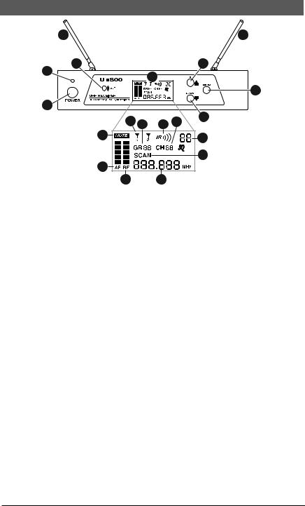
4. QUICK USER CONTROLS GUIDE
3 |
-800 RECEIVER: FRONT VIEW |
3 |
|
|
|
4 |
16 |
|
2 |
5 |
|
|
|
18
1
9 |
11 |
10 |
12 |
17 |
|
||||
6 |
|
|
|
13 |
|
|
|
|
|
|
|
|
|
14 |
7 |
|
|
|
|
815
1.POWER BUTTON BUTTON push in to power receiver ON or OFF
2.POWER LED LED indicates receiver is turned ON
3.DUAL ANTENNAS permanently mounted., rotate to 45° as shown for optimal reception
4.ASC/IR infrared LED window for sync receiver and transmitter. Transmits LED Infrared signal for linking the receiver to the transmitter for frequency downloads
5.LCD DISPLAY shows receiver current status
6.MUTE ICON indicates audio muted
7.AF INDICATOR displays received Audio level
8.RF INDICATOR displays received radio signal level
9.A/B INDICATORS indicates diversity A or B antenna reception when transmitter is on
10.IR INDICATOR INDICATOR indicates IR ASC™ receiver-to-transmitter channel sync is in progress
11.GROUP indicates group number
12.CHANNEL indicates channel number
13.MUTE LEVEL shows muting level
14.SCAN ICON indicates scanning is in progress
15.FREQUENCY indicates frequency in MHz
16.UP BUTTON BUTTON to change the receiver MUTE level up, GRP/CH up by one step at a time or activate ASC™ sync in IR menu
17.DOWN BUTTON to change the receiver MUTE level down, GRP/CH down by one step at a time
18.MENU BUTTON repeatedly press the button to advance to the next menu, or press once to start the Auto Scan/IR/Sync function or to manually select GR/CH. Use MENU BUTTON for easy set up with ONE TOUCH PROGRAMMING. Start the IR link download of the receiver’s selected channel to the transmitter. Position the transmitter IR RECEPTOR WINDOW (37,44) 6-12” away from the receiver
IR window, press the MENU button once and wait five second, the receiver will
4
SCAN and IR automatically for the open channel. The IR INDICATOR will flash for 2 seconds. If the IR data download is successful, the receiver’s RF (8) and A/B INDICATORS (9) will also be on, indicating channel transfer is complete. See also section “6. Selecting Group/Channel, IR Programming and
Simultaneous Multichannel Operation”
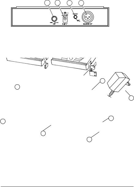
U-800 RECEIVER: BACK VIEW
19 20 21 22
19.UNBALANCED LINE OUT ¼” JACK Line level audio output, adjustable with Volume control
20.DC INPUT JACK For connecting external AC/DC adapter to power receiver
(DC22VDC/400mA)
21.VOLUME CONTROL Selects desired output volume level for the Unbalanced Line Out
22.BALANCED MIC OUT XLR JACK Audio output at fixed MIC level
24
 25 25
25 25
23
 24 27
24 27
26
27
23.DC POWER SUPPLY ADAPTER 120VAC/22VDC/400mA
24.SIDE MOUNT CLIP removes to leave space for optional rack ears
25.ERM-12 SINGLE RACK KIT optional rack ears for single receiver rack mounting
26.EJC-3 JOINING CLIP supplied with ERM-22 kit for joining two receivers side-by-side for dual rack mounting
27.ERM-22 DUAL RACK KIT optional rack ears for rack mounting two receivers side by side
5

UH-800 HANDHELD TRANSMITTER: FRONT AND BOTTOM VIEW
28.MIC BALL/ ANTENNA windscreen also functions as antenna, so for best operating range do not handle this antenna during use
29.BATTERY COVER unscrew CCW to open battery tube to insert batteries
30.AUDIO INPUT LEVEL normally set at middle position, turn knob with small flat head screw driver for optimum sound
31.TWO AA BATTERIES operating from two AA batteries
32.BATTERY COMPARTMENT holds two AA alkaline or NiMH batteries, observe correct polarity
33.POWER ON LED indicates the transmitter ON (green)
34.LOW BATTERY LED indicates the batteries are weak (red)
35.RF POWER slide the switch to power the transmitter ON or OFF
36.AUDIO MUTE slide the switch to ON or OFF to mute audio with transmitter powered on
37.IR RECEPTOR SENSOR/WINDOW infrared LED sensor for linking the transmitter to the receiver during IR selected frequency downloads
29
28
31
33 |
34 |
30 |
35 |
|
36 |
OFF |
|
ON |
37 32
6
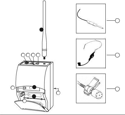
UB-800 BODYPACK TRANSMITTER: FRONT VIEW
38.ANTENNA Removable antenna—should be attached during operation
39.INPUT JACK Locking 3.5mm mini-jack for connecting audio input cord from lapel mic (LT), Headmic™ (LT/HM), or instrument (GT) cable
40.AUDIO MUTE slide the switch to ON or OFF to mute audio with transmitter powered on
41.BI-COLOR BATTERY STATUS LED indicates green for strong usable battery and red for low battery needing replacement
42.POWER ON/OFF slide switch to power receiver ON or OFF
43.INPUT VOLUME LEVEL adjusts input (LT/HM) audio level for optimal sound
44.IR RECEPTOR SENSOR infrared LED sensor for linking the transmitter to the receiver during IR selected-frequency download
45.BATTERY COMPARTMENT holds two AAA alkaline or NiMH batteries
46.LATCHING BATTERY DOOR open fully to insert batteries
47.BELT CLIP on back of unit
48.INSTRUMENT CORD GT cable—connects instrument’s audio output to TX input jack
49.HEADMIC™ Headworn microphone (choice of models)—connects to transmitter input jack
50.LAVALIER MIC Lavalier (lapel) microphone (choice of models)—connects to transmitter input jack
48
38
39 |
40 |
41 |
42 |
49 |
43 |
44 |
50 |
47
 45 46
45 46
7
5. SYSTEM OPERATION
U-800 RECEIVER
Button Function
The POWER ON Button (1) is used to power receiver ON or OFF. When the power button is pressed, the POWER LED (2) and the white backlight on the LCD DISPLAY (5) will light up indicating the receiver is ready. Press the Power button again to turn off the receiver. The power LED and the backlight on the LCD will be off indicating the receiver is off. At power-off the U-800 receiver will store the last settings entered and re-display them at power-on. It can be reprogrammed to any new Group/Channel, or Mute level. The default factory setting is Group 11, Channel 01 and Mute 0 on the first LCD menu screen.
The UP BUTTON (16) is pressed one step at a time to SCAN, IR or to increase GROUP, CHANNEL, MUTE by one level each time
The DOWN BUTTON (17) is pressed one step at a time to decrease GROUP, CHANNEL, MUTE by one level each time
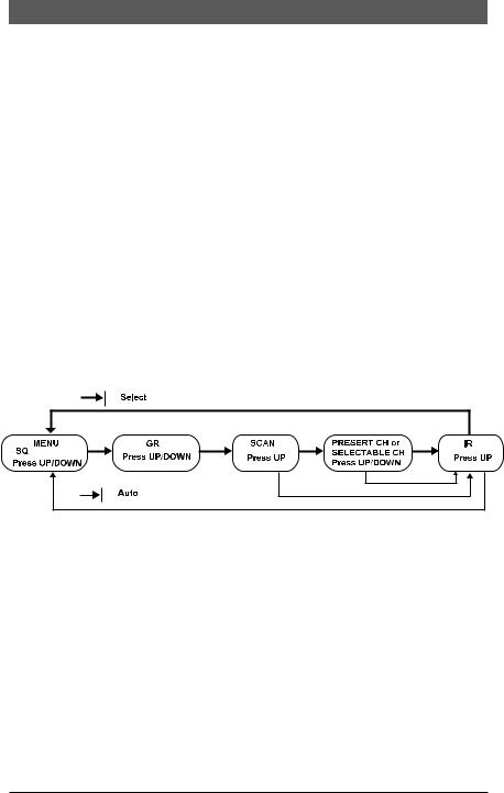
The MENU BUTTON (18) is pressed one step at a time for Auto Scan Frequency or to Automatic GR/CH ASC™ Sync, or if pressed repeatedly the LCD DISPLAY (5) menu will cycle through the following screens.v
During manual programming, press the MENU BUTTON (18) to confirm the selection and advance to the next menu before the Auto Programming Function takes over after 5 sec.
Rack Mounting the Receiver
There are 2 options available for rack mounting the U-800 receiver: singly or side by-side with another U-800 receiver.
a.Single mounting: Remove the receiver SIDE MOUNT CLIP (24) from each side of the receiver (as shown) and slide in the optional ERM-12 RACK EARS (25).
b.Side-by-side double mounting: After removing the SIDE MOUNT CLIPS (24) from both U-800 receivers join the two receivers with the EJC-3 JOINING CLIP (26) and attach the ERM-22 RACK EARS (27) as shown.
(Note: Do not mount the receiver in a rack directly above an amplifier or other source of high heat — this could degrade the performance of the U-800. Always ensure adequate airflow and heat dissipation in any rack configuration.)
8
 Loading...