

SMA-2130
STEREO MONITOR AMPLIFIER
OWNER’S MANUAL
AMPLIFIER
2
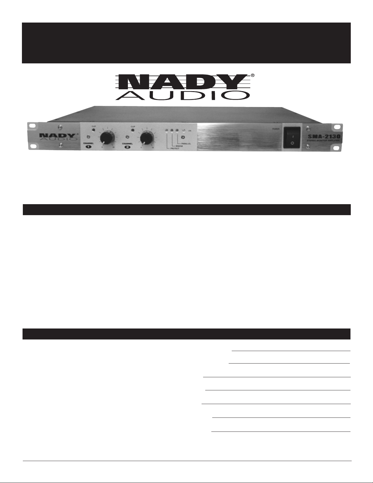
SMA-2130
Stereo Monitor Amplifier
Congratulations on your choice of amplifier — you have purchased one of the finest amplifiers on the market today. This unit
was developed using the expertise of professional sound engineers and working musicians. You will find that your new NADY
AUDIO SMA-2130 has superior performance and greater flexibility than any other amplifiers in its price range. Please read this
manual carefully to get the most out of your new unit.
Thanks for selecting NADY AUDIO as your choice in amplifier.
Date of Purchase
Dealer’s Name
City
State
Zip
Model #
Serial #
CONTENTS
FEATURES
FEATURES ................................................................................2
WARNING ..................................................................................3
INSTALLATION ..........................................................................4
LEGAL INFORMATION..............................................................4
FRONT CONTROL AND CONNECTORS ................................5
REAR CONTROL AND CONNECTORS ..................................6
SPECIFICATIONS......................................................................7
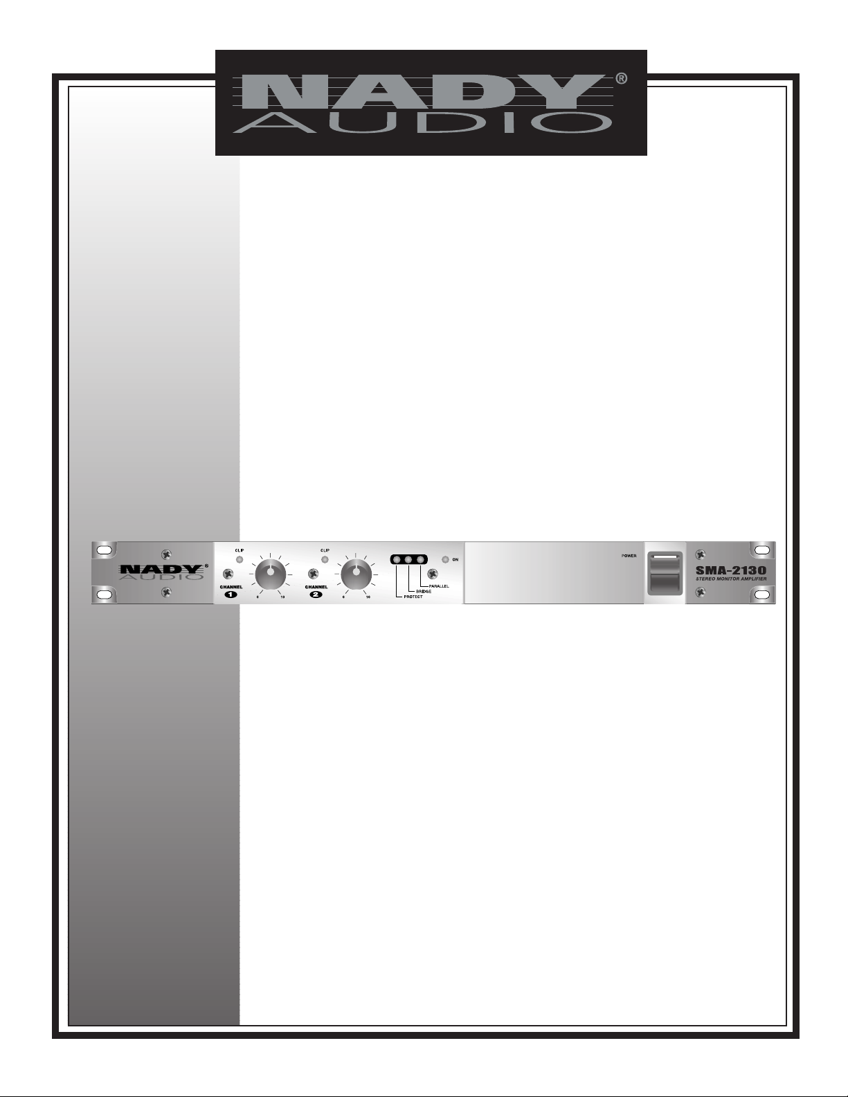
Offering superior clean power and performance with full professional operating features in a roadworthy compact 1U rackspace
chassis, the SMA-2130 is perfect for even the most demanding studio and reinforcement applications.
• Calibrated 40 detent level controls
• Dual cooling quiet mini-fans for optimum output power
• Stereo / Parallel / Bridged mono operating modes with
selector switch
• 1/4" TRS and XLR balanced and unbalanced inputs
• 3 setting input level sensitivity switch
• Binding post and Neutrik Speakon™ outputs; ground-lift
switch
• Complete, advanced safety/reliability features: soft-start turn
on; noise-free on-off; built-in DC offset protection;
independent DC and thermal overload protection on each
channel; short circuit and speaker protection; built-in current
limiter protection
• ~115V (60Hz)/~230V (50Hz) AC select switch
• Clip LED indicators for each channel
• Bridge and Parallel mode LED indicators
• Protect mode LED indicator
• Durable single rack space (1U) steel casing
• 2 x 130W @4 Ohms, 2 x 70W @8 Ohms
Bridge mono: 220W @ 8 Ohms

WARNING
3
IMPORTANT SAFETY INSTRUCTIONS
When using this electronic device, basic precautions should always be taken, including the following:
1. Read all instructions before using the product.
2. Do not use this product near water (e.g., near a bathtub, washbowl, kitchen sink, in a wet basement, or near a
swimming pool, etc.).
3. This product should be used only with a cart or stand that will keep it level and stable and prevent wobbling.
4. This product, in combination with headphones or speakers, may be capable of producing sound levels that
could cause permanent hearing loss. Do not operate for a long period of time at a high volume level or at a
level that is uncomfortable. If you experience any hearing loss or ringing in the ears, you should consult an
audiologist.
5. The product should be positioned so that proper ventilation is maintained.
6. The product should be located away from heat sources such as radiators, heat vents, or other devices
(including amplifiers) that produce heat.
7. The product should be connected to a power supply only of the type described in the operating instructions or
as marked on the product. Replace the fuse only with one of the specified type, size, and correct rating.
8. The power supply cord should: (1) be undamaged, (2) never share an outlet or extension cord with other
devices so that the outlet’s or extension cord’s power rating is exceeded, and (3) never be left plugged into
the outlet when not being used for a long period of time.
9. Care should be taken so that objects do not fall into, and liquids are not spilled through, the enclosure’s
openings.
10. The product should be serviced by qualified service personnel if:
A. The power supply cord or the plug has been damaged.
B. Objects have fallen into, or liquid has been spilled onto the product.
C. The product has been exposed to rain.
D. The product does not appear to operate normally or exhibits a marked change in performance.
E. The product has been dropped, or the enclosure damaged.
11. Do not attempt to service the product beyond what is described in the user maintenance instructions. All
other servicing should be referred to qualified service personnel.
ATTENTION: RISQUE DE CHOC ELECTRIQUE NE PAS OUVRIR
An equilateral triangle enclosing a lightening flash/arrowhead symbol is
intended to alert the user to the presence of uninsulated “dangerous
voltage” within the product’s enclosure which may be of sufficient
magnitude to constitute a risk of electric shock.
An equilateral triangle enclosing an exclamation point is intended to alert
the user to the presence of important operating and service instructions in
the literature enclosed with this unit.

INSTALLATION
4
To ensure years of enjoyment from your NADY AUDIO SMA-2130, please read and understand this manual thoroughly before
using the unit.
INSPECTION
Your NADY AUDIO SMA-2130 was carefully packed at the factory in packaging designed to protect the units in shipment.
Before installing and using your unit, carefully examine the packaging and all contents for any signs of physical damage
that may have occurred in transit.
[Please note: Nady Systems is not responsible for shipping damage. If your unit is damaged, do not return to Nady, but
notify your dealer and the shipping company (if shipped to you) immediately to make a claim. Such claims must be made
by the consignee in a timely manner.]
CONTENTS
• Instruction manual
• SMA-2130 (verify that the unit’s serial number is same as shown on shipping carton)
• AC Power cord
• Warranty Card
RACK MOUNTING
The SMA-2130 fits into one standard 19” rack unit of space (1 3/4”). Parts of the unit can become very warm during use.
This is normal during operation. Care should be taken to ensure that there is enough space around the unit for cooling (at
least 12” or 30cm). Do not place the SMA-2130 on high temperature devices such as power amplifiers, etc., or the unit
may overheat in operation. Also, do not place the unit on speakers as this may cause them to move and/or fall due to
speaker vibrations.
Although the unit’s chassis is shielded against radio frequency (RF) and electromagnetic interference (EMI), extremely
high fields of RF and EMI should be avoided.
POWER CONNECTION
The SMA-2130 has an internal power supply and is designed to operate from an external AC source. Power requirements
for electrical equipment differ from area to area. Be sure to confirm that the voltage selected by the voltage selector switch
on the back panel is proper for your area (120VAC/60 Hz or 230VAC/50Hz) per the information below:
Europe (except UK): 230V, 50Hz
UK and Australia: 240V, 50Hz
USA and Canada: 120V, 60 Hz
For other areas, please check with local authorities.When ready to operate, plug the AC cord into the power source. Make
sure that the unit is turned off before connecting to the AC power source to avoid possible loud transients that can
damage your speakers or your ears, especially when monitoring with headphones.
NOTICE
The information in this document is subject to change, as the Company may make changes to product in order to improve
reliability, design, or function, without prior written notice. No part of this manual may be reproduced or transmitted in any form
or by any means without the written permission of the company.
IN NO EVENT WILL THE COMPANY BE LIABLE FOR SPECIAL INCIDENTAL OR CONSEQUENTIAL DAMAGES,
WHETHER ARISING DIRECTLY OR INDIRECTLY, SUCH AS LOSS OF PROFIT OR GOOD WILL, THAT MAY BE
SUFFERED IN CONNECTION WITH THE PURCHASE OF THIS PRODUCT OR FROM THE BREACH OF ANY
REPRESENTATION OR WARRANTY.
LICENSE
The Company grants the customer a non-exclusive, non-transferable license to use the software, if any, accompanying this
product for internal use on a single computer system. The end user may make a single copy of the software solely for backup
purposes; otherwise, no copies may be made of the software or any part thereof. No other license of any kind is granted to
any part of the product or any of the intellectual property therein.
LEGAL INFORMATION

5
FRONT CONTROLS AND CONNECTIONS
(5)
(4)
(6)
1. POWER SWITCH
To turn the unit ON or OFF, press the upper or lower portion
of this button.
CAUTION: Always turn on your power amplifier last, after all
your other connected equipment, and always turn off your
power amplifier before your other connected equipment.
2. POWER LED INDICATOR
Lights when the unit is on.
3. BRIDGE / PARALLEL INDICATORS
These indicators will light when the corresponding mode of
operation is selected with the mode selector switch. No light
means the unit is in Stereo mode.
4. PROTECTION LED INDICATOR
This LED illuminates when the unit is overheated, or when a
shorted load or DC is detected at the amplifier output. When
this LED lights up, turn OFF the power and check the
output’s connection to verify that it is correct, then turn ON
the power again. The amplifier will reset itself when the
problem is corrected. This LED will also light briefly when
the unit is powered on.
5. LEVEL CONTROLS
These control the level of signal coming into each channel.
Turn these controls counterclockwise if the peak LEDs
illuminate steadily (indicating too strong an input signal). To
be safe, it is also suggested these controls be turned fully
counter-clockwise before powering on the unit, in case there
are any loud input signals.
6. CLIP LED INDICATORS
These LEDs illuminate if any section of the power amplifier’s
output is within 3dB of clipping. Occasional blinking of these
LEDs is acceptable, but if they remain on more than
intermittently you should turn down either the amplifier’s level
control or reduce the output level of the preceding
component to avoid audible distortion.
(1)
(2)
(3)

REAR CONTROLS AND CONNECTIONS
6
(12)
7. BALANCED INPUT CONNECTORS (1/4" TRS & XLR)
These 1/4" (6.3mm) TRS (Tip/Ring/Sleeve) phone jacks and XLR
jacks are compatible with balanced inputs and are wired as
Tip/Pin 3 = (-), Ring/Pin 2 = (+), and Sleeve/Pin 1 = Ground.
Input impedance is 14K Ohms.
Since the channel TRS phone jacks and XLR jacks are wired
internally in parallel, you can parallel this unit with another
amplifier by using either the LINE 1/4" jack or the XLR jack
(depending on which you’re using to input your signal) to output
the signal to the input jack of the other amplifier.
The 1/4" TRS phone jacks can also be used for unbalanced
inputs. For TRS phone plugs, simply connect the unused side of
the balanced input to ground. For 1/4" TS phone plugs, no
change is necessary for compatibility with this input. Balanced
input signals are recommended as they are less prone to AC
hum. For long cable runs a source of less than 600 ohms output
impedance is needed to avoid signal loss. For short cable runs
an unbalanced signal input should be suitable.
(Note: Do not use both unbalanced and balanced cables in the
same set-up as that can unbalance all the connections when
daisy-chaining, resulting in hum.)
For stereo (two-channel) operation, use the inputs for both
Channel 1 and Channel 2; for parallel or bridged mono operation,
use only Channel 1 input. (See 9. MODE SELECTOR
SWITCHES below for more explanation.)
8. INPUT LEVEL SWITCH
Sensitivity slide switch offers 3 sensitivity inputs of operation;
0.77 volts, 1.0 volts & 1.44 volts.
9. MODE SELECTOR SWITCH
The SPA Series amplifiers offer 3 modes of operation:
PARALLEL, STEREO & BRIDGED. Slide the switch to one of the
three positions for your application.
• PARALLEL (MONO) INPUT — This mode allows both
channel outputs to operate in parallel with the same signal. In
this mode, use channel 1 input and Level Control to operate
Channel 1 and Channel 2 Speaker Outputs. Channel 2 input
is not operational.
(11)
• STEREO INPUT — This is the most common mode
generally used, and allows independent control of 2 separate
signals such as stereo, main and monitor live mixes, and biamp operation (highs in one channel and lows in the other).
• BRIDGED MONO — This mode combines the power of
both channels to drive a single speaker. Connect the input
signal to Channel 1 input for bridged mono operation. When
in Bridged mode, use the red binding post (banana jack)
outputs only. If Channel 1 and Channel 2 outputs are used,
the Speakers will be out of phase.
(CAUTION: This amplifier can deliver high power into a speaker.
Make sure that the speaker can handle the power output of this
amplifier)
10. GROUND LIFT SWITCH
Switch to disconnect the chassis from ground if necessary to
eliminate hum caused by ground loops.
11. SPEAKER OUTPUT CONNECTORS
Speakon™ and binding post (banana jack) outputs are
compatible with a speaker load of 4ohms or greater (8 ohms or
greater for bridged operation). Do not use less than an 8 Ohm
load when in Bridged mode. Connections are as depicted on the
rear panel.
12. FUSE HOLDER & POWER CORD CONNECTOR
This fuse holder contains an AC primary fuse. When this fuse
blows, replace it with the same type fuse, size and power rating
(see SPECIFICATIONS). If it continuously blows, stop replacing
the fuse and refer servicing to qualified personnel. The cord
connector is used to connect the AC power source to your power
amplifier.
(CAUTION: After checking the AC supply voltage, be sure that
the correct fuse is in the fuse holder.)
CAUTION: DO NOT REMOVE THE AC PLUG CENTER
GROUNDING PIN.
13. INPUT VOLTAGE SELECT SWITCH (BOTTOM PANEL)
Select 115V/60Hz or 230V/50Hz as appropriate for your area.
(CAUTION: Selecting the wrong voltage can damage your unit.
See also POWER CONNECTION, pg 6)
(10)
(9)
(7)
(8)
(7)
(13)
Bottom
Panel

7
SPECIFICATIONS
EIA Output Power RMS 8Ω 70W + 70W
1kHz, THD maximum 1% 4Ω 130W + 130W
8Ω Bridged 220W
Less than 8Ω Bridged or 4Ω Per Side is not recommended.
POWER SPECIFICATIONS
INPUT SENSITIVITY ..............................................................0.77V/26dB/1.4V
INPUT IMPEDANCE ..............................................................20KΩ Unbalanced & Balanced
FREQUENCY RESPONSE ....................................................10Hz~50KHz +/-3dB
MAXIMUM INPUT LEVEL........................................................21dB/6V
DAMPING FACTOR (f=1KHz 8Ω) ..........................................>150
SLEW RATE ............................................................................35V/uS
DISTORTION ..........................................................................<0.04%
S/N RATIO A-Weighted RMS..................................................>80dB
POWER SUPPLY ....................................................................Voltage selectable 110-120V or 220~240V AC 50/60Hz
FUSES ....................................................................................Standard IEC receptacle with built-in fuse holder
115VAC ~ 5A/250V
230VAC ~ 3A/250V
ELECTRICAL SPECIFICATIONS
GENERAL SPECIFICATIONS
PROTECTION ..........................................................................Full short circuit, current limited, DC fault, AC line fuse, thermal, Power on/off transients,
FRONT PANEL ........................................................................Power switch, Channel 1 and Channel 2 Level controls
REAR PANEL ..........................................................................Stereo/Bridge/Parallel selector, Input Level selector,
LED INDICATORS ..................................................................Channel 1 and Channel 2 Clipping, Protect, Bridge, Parallel, Power
POWER ....................................................................................IEC power cord jack
INPUTS ....................................................................................Active balanced XLR and 1/4" (6.3mm) TRS
OUTPUTS ................................................................................Binding posts/Banana jack, Speakon
DIMENSIONS (WXDXH) ..........................................................19" x 9.84" x 1.73" (483 x 250 x 44mm)
WEIGHT ..................................................................................18.25lbs. (8.28Kg)
The specifications above are correct at the time of printing of this manual. For improvement purposes, all specifications for this unit, including design
and appearance, are subject to change without prior notice.

NADY SYSTEMS, INC. • 6701 SHELLMOUND STREET, EMERYVILLE, CA 94608
Tel: 510.652.2411 • Fax: 510.652.5075 • www.nady.com
SERVICE FOR YOUR NADY AUDIO PRODUCT
(U.S.) Should your NADY AUDIO product require service, please contact the Nady Service Department via
telephone at (510) 652-2411, or e-mail at service@nady.com.
(International) For service, please contact the NADY AUDIO distributor in your country through the dealer from
whom you purchased this product.
DO NOT ATTEMPT TO SERVICE THIS UNIT
YOURSELF AS IT CAN BE DANGEROUS
AND WILL ALSO VOID THE WARRANTY.
 Loading...