

Page 1
V. 2005.2
User manual
Page 2

OverviewContence
Contence
Accessories 3
Mounting 4
Connections and set-up 9
Remote control 14
Get started 18
Functions 24
Q&A and practical information 33
Congratulations with your high definition LCD TV
Passion for Picture:
We have put all our efforts in creating this unique TV. We hope that you will
enjoy using it as much as we enjoyed creating it!
2
Please read this manual before using the product. Keep it for further reference.
Page 3

Please check that you have received the following accessories together with your LCD TV.
Remote control
Batteries for the remote control (Size"AAA" R6P)
Desktop-stand plate
Rubber list for desktop-stand
Rubber feet for desktop-stand plate
Screws for desktop-stand (4 pcs 4x12mm + 1 extra)
Skruer til VESA vægbeslag (4 pcs 4x5mm + 1 extra)
Warning label for mounting wallmount/VESAmount
220 V power cord
CD-ROM with manual and other information
3m minijack soundcable with goldconnectors
Y-adapter with goldconnectors for centre speaker
Cloth for cleaning of the frontglass
Postcard remote control
Accessories
Introduction
3
Page 4
Chapter 1 Mounting
In this chapter you will find out how to mount your TV on the complementary desktop-stand, or on the tablestand or
the floorstand which you bought as an option. You will also be shown how to use the wallmount.
4
Page 5
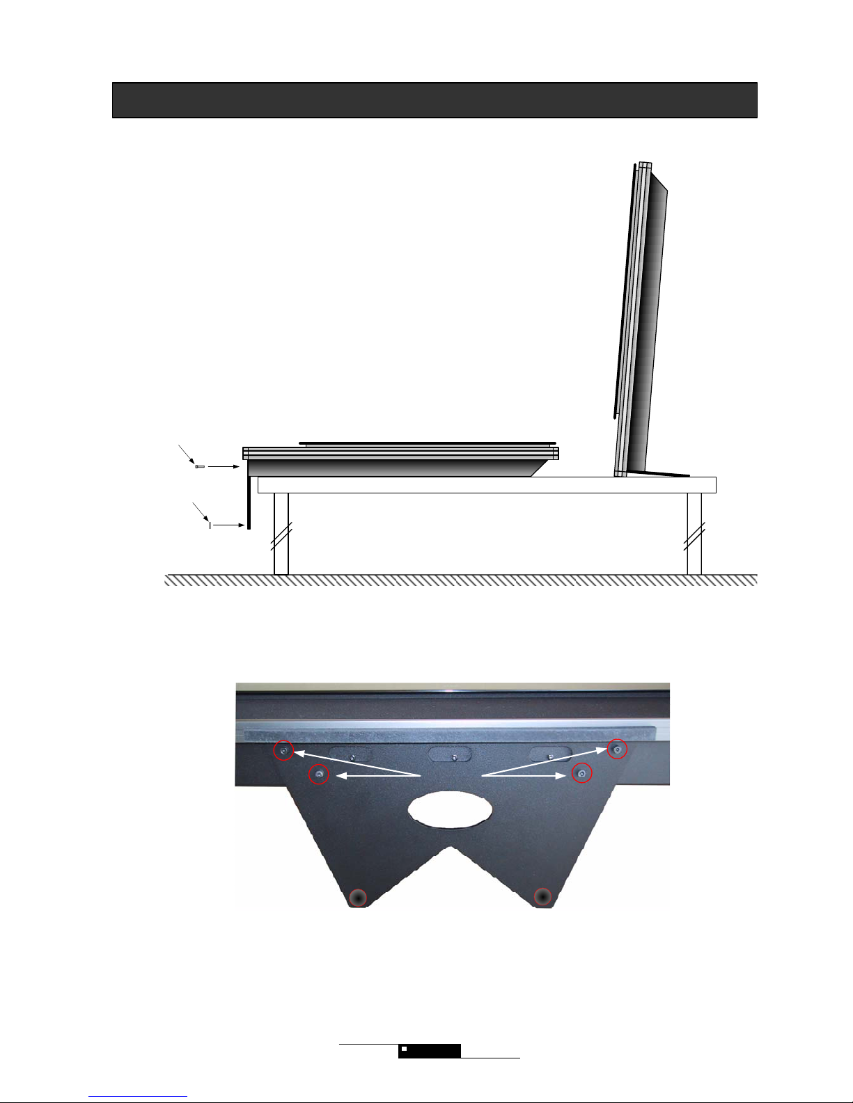
M4x12 mm
4x12mm
Mounting the desktop stand
Introduction
Mount the desktop as illustrated below:
5
2 x rubber feet
Your LCD TV can be put on the location of your choice. Always take care that the air can flow free through
the ventilation holes on the back of the screen. Never put the TV in a closed bookcase or hang it flat on the
ceiling, because in this way air cannot flow free .
Page 6
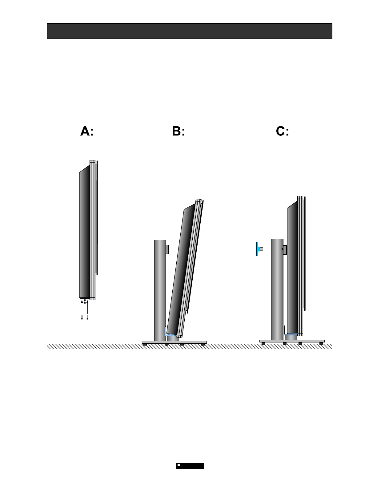
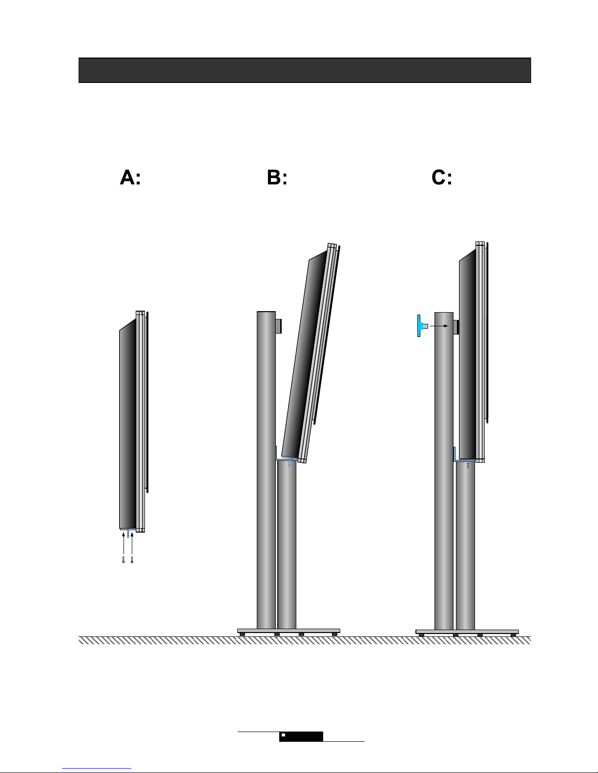
Mounting the table stand
Introduction
Mount the TV on the tablestand as illustrated below. Check also the instructions that accompany the stand.
6
4 x M4x8mm
Screw the to fingerscrews in the backplate
It is most convenient to stand with your face
to the frontglass during this operation
Position the screen in the
hole
Mount the botton piece with 4
screws
Page 7
Mounting the floorstand
Introduction
Mount the floorstand as illustrated below. Check as well the information delivered together with the floorstand.
4 x M4x8mm
Mount the
bottompiece with 4
screws
Screw the 2 fingerscrews in the backplate
It is most convenient to stand with your face
to the frontglass during operation
Position the screen in the
hole
7
Page 8
8
Your LCD TV can be put on the location of your choice. Always take care that the air can flow free through
the ventilation holes on the back of the screen. Never put the TV in a closed bookcase or hang it flat on the
ceiling, because air cannot flow free in this way.
Remember that the warranty does not cover for faulty installation or faulty use of the mounting.
Fix the wallmount Screw the fingerscrews in the backplate Hang the screen on the wallmount
Spacer
min 20mm
2x big
fingerscrews
Wallmount
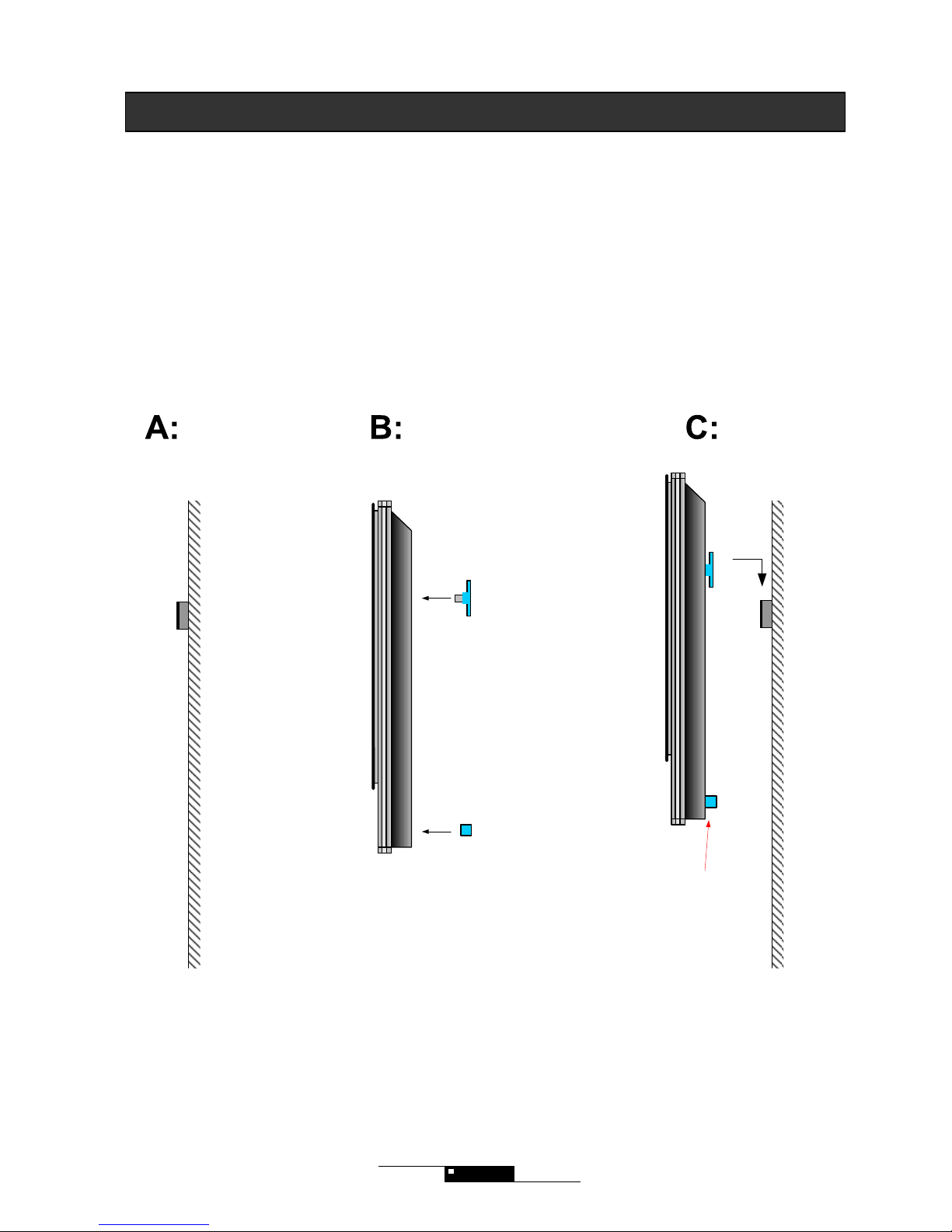
Introduction
Mount your wallmount as illustrated below
1. Fix your wallmount to the wall. Make sure that it hangs straight and that it is fixed well.
2. Screw the to fingerscrews into the backplate and bring the spacer in place.
3. Connect the antenna connection
4. Connect the other connections
5. Connect the powercable
6. Let the fingerscrews rest on the wallmount
7. Insert the powercable in the powersocket
Important:
The spacer makes sure that the air
can flow free.
Page 9
M4 x 5mm
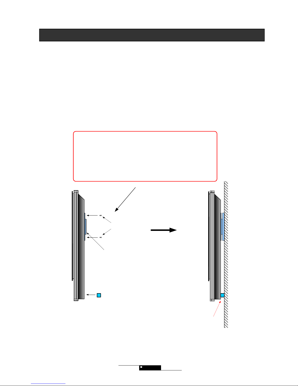
VESA wall bracket
VESA wallmount
Introduction
We strongly recommend you to use the original wallmount. Vesa wallmounts can be used but they do not give the
same stability. Often, VESA wallmounts are not dimensioned for the use of screens of this weight. NEVER use the
screws that are delivered together with a VESA mount. This will damage your TV.
1. Fix the VESA wallmount with the M4x5mm screws, delivered together with you TV.
2. Fix the other part of the VESA wallmount to the wall.
3. Connect the antenna connection
4. Connect the other connections
5. Connect the powercable
6. Fix the TV to the wall
7. Insert the powercable in the powersocket
Your LCD TV can be put on the location of your choice. Just always take care that the air can flow free
through the ventilation holes on the back of the screen. Never put the TV in a closed bookcase or hang it
flat on the ceiling, because air cannot flow free in this way.
Remember that the warranty does not cover for faulty installation or faulty use of the mounting.
9
! Warning about VESA mounting !
Only use the M4x5mm screws in the VESA mounting holes on the back
of the screen. Use of longer screws will damage your TV!
Maximum insertion is only 3,5 mm. Longer insertion will damage the TV!
Spacer
min 20mm
Important:
The spacer makes sure that the air
can flow free.
Page 10
Chapter 2 Connections and set-up
In this chapter you get an overview of what kind of objects can be connected to your LCD TV. Your TV has a lot of
connections/sockets. The objects you want to connect have the same kind of sockets. You will get some examples.
10
Page 11

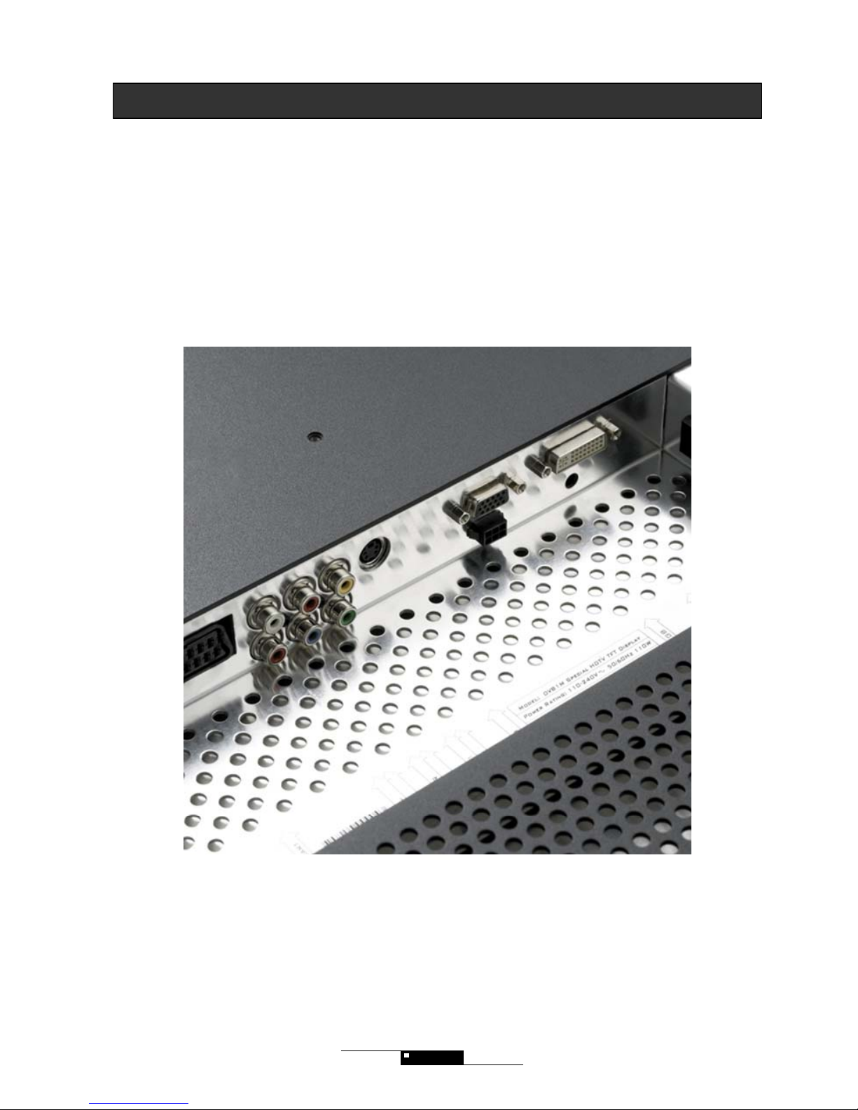
Connections
Introduction
Overview of the different sockets
2 3 4 5 8 9
1. Audio out L/R (2xRCA)
2. DVI Audio in/VGA audio in (3,5mm stereo jack)
3. TV-antenna
4. SCART with RGB
5. Audio in L/R (for AV 1 / S-Video / Component) (2xRCA)
6. Component (interlaced eller progressive scan) (3xRCA)
7. AV1 video in (1xRCA)
8. S-VIDEO in (1xRCA)
9. VGA (PC)
10. Service connection
11. DVI-D (Digital Visual Interface) with HDCP
12. Powersocket (110 - 240 V)
11
5 6 667 10 121 11
Sockets on the left side (fast access board)
13. AV 2 video in (1xRCA)
14. Audio in L/R for AV 2 (2xRCA)
15. Audio out L/R via minijack (3,3 mm stereo jack)
for headphones
The Y-adaptor should be us ed when you
want to use your TV as a centre speaker
in a surround system
The audiocable can be used when you
have connected somthing to the VGA or
DVI socket and you want to have sound
of this source in the speakers of your
LCD TV
The Y-adaptor and the audiocables that are delivered together with your TV, can be used in
the following way:
Page 12
Set-up
Introduction
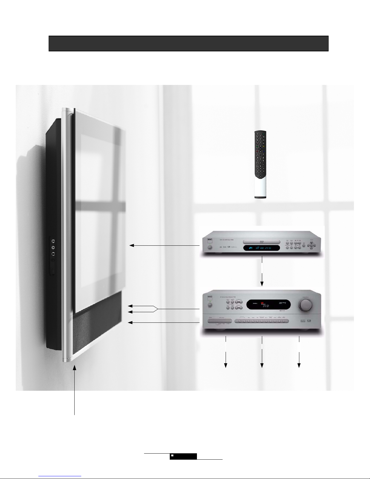
The picture below shows you the different connections in a surround system set-up.
Scart RGB or
Component video signal
Center speaker
Pre-Out signal
Phono L
Phono R
S-video signal for Receiver OSD
Surround
speakers
Front L&R
speakers
Subwoofer
Digital Optical or
Digital Coaxial signal
T533 /
T513
T753/
T743
TV-antennasignal
12
DV 1
Page 13

Play Console
Digital Camera
Camcorder
Headphones
Video 2
Fast Access Interface for:
The pictures below show different possibilities:
13
Set-up
Introduction
DVD-D (digital RGB)
with HDCP
VGA (analog RGB)
Stereo Audio (mini
Jack)
Component Video
Center speaker
Pre-Out signal
S-video
for Receiver OSD
RGB SCART
Audio/Video signal
TV-antennasignal
or Cable TV
PC / Laptop
High End DVD Player
Digital Satellite Receiver
DVB-T Setup Box
Sattelite Receiver
HD Recorder
VHS Video
Surround
speakers
Front L&R
speakers
Subwoofer
Digital Audio
Audio out L&R
Page 14

Chapter 3 Remote control
In this chapter you will get an overview over the use of your remote control. As a special feature, your TV can be
controlled by almost all B&O remote controls. An overview of the use of the specific buttons of the different types,
can be found as a pdf file on the CD delivered together with your TV. You can as well use NAD HTR-2. If you did
not receive our aluminum remote, but a plastic one, you will receive an aluminum remote for free at a later date. You
just need to send us the included postcard.
The aluminium remote control is of the learning type and has a USB interface. It can control 6 devices, meaning that
it is the only remote control you need!
14
Page 15

MUTE
V.SIZE PIP
EXIT
MST
PG
INFO
PICTURE STILL
SOUND SLEEP TIME BRIGHT
ERASE SKIP INSERT REPLACE
Menu/Set
TV/Video
NAD
PG+
PG-
VOL- VOL+
i?
0
7 8 9
PRE
PG
TEXT
4 5 6
1 2 3
On/Off
Picture in Picture (PIP)
Mute sound
Volume up and down
Choose source
Picture setting
Skift function in the osd menu
Quit OSD menu or quit submenu
Choose pictureformat:
4:3 Lettebox Lettebox Title
TV mode Auto Mode Fill screen
Text TV
OSD control buttons
TV channel up and down
Insert channel
Erase channel
Skip channel
Brightness in 7 steps
Still picture
Previous channel and subside menu in Text
TV
Show the time
Replace previous channel
Sleep function
Sound settings
Mono / Stereo sound
Channel information
1: TV
2: RGB Scart
3: AV1
4: AV2
5: S-video
6: Component Interlaced
7: Component P-scan
8: VGA/analog RGB
9: DVI/digital RGB
Simple model
Remote control
This remote control guarantees you a simple and fast access to all main functions.
15
Activate autobright: EXIT +
TV shows 5 fast blue blinks
Deactivate autobright: EXIT +
Page 16

Text TV
PIP (Picture In Picture) /
Record
Menu / Set Exit / Back
Choice of picture format
Still picture
Picture settings
Brightness in 7 steps
Time
Last channel and subsides Text-TV
Next channel
Previous
channel
Volume up
Volume down
Text TV keys
Insert channel in the programme edit menu
OSD navigation keys
On / OffMute sound
Source menu/Go
TV mode
Video mode (programmable)
Hard Disc Recorder mode (programmable)
AUX1 mode (programmable)
DVD mode (programmable)
Amplifier/receiver mode (programmable)
Digital TV mode (programmable)
Text TV keys / Zoom +
Skip/unskip channel in the programme edit menu
Text TV keys / Zoom -
Delete channel in the programme edit menu
1: TV
2: RGB Scart
3: AV1
4: AV2
5: S-video
6: Component Interlaced
7: Component P-scan
8: VGA/analog RGB
9: DVI/digital RGB
Remote control DV 1
This programmable remote control can control up to 7 devices. For more information about programming, see the
pdf file about the remote control on the CD. As a standard, the remote control is programmed as follows:
AMP: NAD T753, DVD: NAD T533.
16
Text TV keys
Re-insert channel in the programme edit menu
Activate Autobright: EXIT +
TV shows 5 fast blue blinks
Deactivate Autobright: EXIT +
Page 17

17
HTR 2
Remote control
It is possible to use NADs HTR 2. We recommend the following settings :
ON/OFF
Last channel
Mute sound
Volume up / down
Activate OSD menu
Replace channel
Skip or keep channel
TV mode
Choose source
Shift function in OSD menu
Leave OSD menu or EXIT submenu
Choose pictureformat
4:3 Lettebox Lettebox Title
TV mode Automode Fill screen
channel Info
OSD control buttons
TV-channel up / down
Insert channel
Delete channel
Brightness
Picture in Picture (PIP)
Still picture
Picture settings
HTR 2
Sleepfunction
1: TV
2: RGB Scart
3: AV1
4: AV2
5: S-video
6: Component Interlaced
7: Component P-scan
8: VGA/analog RGB
9: DVI/digital RGB
OSD TIME
Text TV
Back to TV after Text TV
Page 18

Chapter 4 Get started
In this chapter, you get an overview over the basic functions
18
Page 19

Power ON/OFF
Get started
POWER ON/OFF
Switching on the TV
1. Switch on the TV, using the switch on the left side.
The blue light in the speaker area will light up in 1-2 seconds.
2. Wait 5 seconds.
3. Press on your remote to turn on the TV (If nothing happens, try again,
pressing the TV button first).
Your TV needs 10-15 minutes to operate in full brightness
Switching off your TV
1. Press on your remote control.
We recommend you to switch off your TV, using the switch on the left side, if the
TV is not used during a longer period.
The TV goes into stand-by, if there is no signal in more then 15 seconds.
Pressing TV, GO, PG+, PG- will turn the TV on again.
Choose channel
To see the last channel, press Pre PG on the remote.
Volume Control
Mute sound
Use VOL up, VOL down.
Press
To choose the last channel
Use PG+ / PG- or the numeric buttons to choose a TV channel
9
19
Page 20

Choose source
Get started
Choose source (GO)
The different sockets your TV comes with, give you a lot of possibilities. On top of a scart socket, your TV is
equipped with Component with progressive scan and DVI that can be used together with the newest DVD players.
Just press ”Go” to see the source menu. Use the navigation keys, together with ”Go” to choose a source. You can
also press ”go” + ”the specific number” to switch fast.
Standby mode:
If you choose a source and there is no cable connected, the TV will give the
message ”no signal”. Shift source using the ”GO” button. The TV goes into
stand-by, if there is no signal in more then 15 seconds. Pressing TV, GO, PG+,
PG- will turn on the TV again.
If you have selected TV as a source and you connect a DVD player via scart,
your TV will automatically switch to scart. Switching off the DVD player, will bring
you back to TV. You can go back to TV mode, by pressing PG+, PG-.
1: TV
2: RGB Scart
3: AV1
4: AV2
5: S-Video
6: Component Interlaced
7: Component P-scan
8: VGA/analog RGB
9: DVI /digital RGB
Standard TV mode (RF).
Scart from a DVD player or HD-rec order, with RGB-signal.
Use the socket on the side of the TV for fast access to
camcorders, digital cameras or Play Station.
S-Video for your DVD-player or HD-recorder.
Component Interlaced for DVD, HD-recorder or Set-up box.
VGA for a pc or multimedia device
Component progressive scan for a DVD player that
supports progressive scan
Digital signal with HDCP for your DVD, PC box or set-up box
with DVI socket.
This digital socket gives you the best quality
20
Use AV1 only as a emergeny solution, because of the
connections’ limited picture quality.
Page 21

SOUND
MENU UP DOWN EXIT
VOLUME 25
BALANCE 0
SOUND MODE User
EQUALIZER Press MENU/GO
AVC On
TV SETUP
MENU UP DOWN EXIT
AUTO SCAN Press MENU/GO
MANUAL SCAN Press MENU/GO
FINE TUNE 50
EDIT Press MENU/GO
PICTURE
MENU UP DOWN EXIT
BRIGHTNESS 50
CONTRAST 50
COLOUR 50
SHARPNESS 50
TEMPERATURE Normal
RECALL Press MENU/GO
TIME
MENU UP DOWN EXIT
SLEEP Off
WAKE UP Press MENU/GO
TIME Press MENU/GO
AM / 24 HOUR MODE 24 Hour mode
EDIT PROGRAM
S 01 TV2_ _ _ _ S 02 DR1 _ _ _ S 03 DR2 _ _ _
S 04 RTL_ _ _ _ S 05 SULO _ _ S 06 SUPE _ _
S 07 _ _ _ _ _ _ S 08 _ _ _ _ _ _ S 09 _ _ _ _ _ _
DELETE SKIP SET UP DOWN LEFT RIGHT EXIT
EQUALIZER
120 Hz 50
500 Hz 25
1.5 kHz 42
5 kHz 33
10 kHz 63
SPATIAL 50
UP DOWN LEFT RIGHT EXIT
AUTO SCAN
SYSTEM BG D/K I
STORAGE P 1
SCAN Press MENU/GO
UP DOWN LEFT RIGHT EXIT
MANUAL SCAN
SYSTEM BG D/K I
STORAGE P 1
BAND Cable
CHANNEL 35
UP DOWN LEFT RIGHT EXIT
21
OSD menu on a video background
Overview OSD menu
Get started
The OSD menu is build up around keywords: Picture (to adjust the picture), Sound (to adjust the sound), Misc. (to
choose how the menu is shown), Time (to adjust functions related to time) og TV setup (for TV channel set-up).
MISC
MENU UP DOWN EXIT
VIDEO SIZE TV mode
OSD LANGUAGE English
OSD SHEET Opaque
OSD POSITION
V3.0-PD-LEA6o DALVIG
Remark:
On every source you can adjust picture, without interfering the
settings of the other sources. It that way you can have your
favourite setting for every source, enjoying the best available picture
quatlity. The different settings are saved by the TV.
Page 22

Component p-scan, DVI and VGA mode:
Overview OSD menu
Get started
In Component p- scan, DVI og VGA you have a wider choice of settings.
You can adjust each RGB (red, green and blue) colour individually, choosing "User" under colourtemperature. It is
recommended to make small adjustments, one colour at the time.
In the submenu you can select the position of the picture. This can be necessary, because DVD players do not
always centre the picture in the same way.
You can also choose PIP (Picture in Picture) on these three sources.
PICTURE
MENU UP DOWN EXIT
BRIGHTNESS 50
CONTRAST 60
POSITION Press MENU/GO
TEMPERATURE User
RED 60
GREEN 60
BLUE 60
PIP
MENU UP DOWN EXIT
PIP ON/OFF PIP off
PIP SOURCE TV
AUDIO SOURCE PIP
PIP POSITION
POSITION
H-POSITION 50
V-POSITION 50
PHASE 50
H-SIZE 50
UP DOWN LEFT RIGHT EXIT
22
H-position moves the total picture to the left or the right.
V-position moves the total picture up or down.
Phase adjusts the phase
H-size enlarges or diminishes the picture horizontally
All adjustments are minor.
PIP Source makes it possible to choose between TV,
scart, AV1, AV2 og S-video. On top of that you can
choose to receive sound from the prime source or the PIP
source.
Page 23

You can change the picture format by pressing F(format). The red
frame is the screen of your LCD TV
Scales 4:3 formatet, so it fits to the size of the screen without
maintaining the ratio between width and heigth.
Use this format when you use a DVD player and the
programme is in 16:9 (1.78:1 og 1.85:1) or 2.35:1
Traditional 4:3 TV format
This is the basic format for convenient TV watching.
The ratio between width and heigth is kept in the middle, but not
at the left and right side. This means that you can see 4:3 TV
and 16/9 programmes without making compromises. Most
information is at your disposal and picture quality and sharpness
remain high.
MISC Justering
"Fit Aspect" mode
"Fill screen" mode
18
23
4:3
1.33 : 1
format
4:3
1.33 : 1
format
4:3
1.33 : 1
format
Sub-title text line #1
Sub-title text line #2
Sub-title text line #1
Sub-title text line #2
16:9
1.85 :1
1.78 : 1
format
"AUTO" mode
Use this format only, when you have choosen scart as source.
The picture will automatically change between 4:3 and 16:9.
Get started Picture format
Picture format
"Letter Box" mode
This is a 4:3 picture where you zoom in, so the picture fits
horizontally. The consequence is of course that a part of the
picture disappears in the top and the bottom.
You can choose this format if you would like to keep the ratio
between width and height, using the available place or when
the input signal is letterbox.
As ”Letter Box”, but you get more of the bottom then of the top to
allow for two text lines.
Can be used in the same way as ”Letter Box”, where subtitles are
very important.
"Letter Box Title" mode
"TV" mode
4:3
1.33 : 1
format
Page 24

Chapter 5 Functions
In this chapter you will get more information about the different functions of your LCD TV. Your TV is for instance
equipped with an ambient light sensor, which measures the light in the room and automatically adapts the
brightness.
24
Page 25

1. Select TV
2. Press Menu
3. Select ”TV SETUP” in the main menu
4. Press GO
5. Select "AUTO scan" in the submenu
6. Select TV-system
B/G D/K I for Denmark/Norway/Sweden and Benelux
L for Secam
7. Select "scan" and press GO. Your TV will start to scan all the available
channels, and saves them in the same order they appear.
8. Press EXIT in case you want to stop scanning.
If you desire to add a channel from another TV-system (satelite), you can use the above
procedure.
You can save up to 99 channels.
1. Select TV
2. Press Menu
3. Select "TV SETUP" in the main menu
4. Press GO
5. Select "MANUAL SCAN" and press GO
6. Select ”CHANNEL” and use the navigation keys and
If you found a channel you want to stock, you can add it by pressing,
or
key: inserts a channel
key: replaces a channel
You can continue your search by pressing or
6. Press EXIT to stop
Manuel Scan
TV SETUP
MENU UP DOWN EXIT
AUTO SCAN Press MENU/GO
MANUAL SCAN Press MENU/GO
FINE TUNE 50
EDIT Press MENU/GO
TV SETUP
MENU UP DOWN EXIT
AUTO SCAN Tast MENU/GO
MANUAL SCAN Tast MENU/GO
FINE TUNE 50
EDIT Tast MENU/GO
AUTO SCAN
SYSTEM BG D/K I
STORAGE P 1
SCAN Press MENU/GO
UP DOWN LEFT RIGHT EXIT
Automatic or manual selection
TV channel selection
Automatic channel selection
MANUAL SCAN
SYSTEM BG D/K I
STORAGE P 1
BAND CABLE
CHANNEL 35
UP DOWN LEFT RIGHT EXIT
25
Page 26

Channel edit
TV channel selection
Channel edit
1. Select TV
2. Press Menu
3. Select "TV SETUP" in the main menu
4. Press Go
5. Select "EDIT" in the submenu
6. Press Go
In the submenu ”EDIT PROGRAM” will appear.
7. Select the channel you want to change, using the navigationkeys:
Use to proceed fast (9 channels at the
time), use to proceed one channel at the time.
8. Press Go to choose "program to edit mode" as shown on the right.
Now you can change the channel number using and . You can
change the channels’ name using and then .
You can use one of the below mentioned functions.
Press after you have selected the channel you want to delete. The
selected channel will be deleted. You cannot delete a channel if you
are in the ”program to edit” mode. In this case you need to press exit
first.
Delete channel
Skip channel
Press . An ´s´ will be shown in another colour on the left side of
the channel number. To regret, press again. The coloured ’s’ will
disappear and you can use PG+ or PG- or the NUMMERIC keys.
Channel without
a name or empty
channel
02: shows the channel number
DR1: TV channel name
TV SETUP
MENU UP DOWN EXIT
AUTO SCAN Press MENU/GO
MANUAL SCAN Press MENU/GO
FINE TUNE 50
EDIT Press MENU/GO
SYSTEM B/G D/K I
EDIT PROGRAM
S 01 TV2_ _ _ _ S 02 DR1 _ _ _ S 03 DR2 _ _ _
S 04 RTL_ _ _ _ S 05 ZULU _ _ S 06 SUPE _ _
S 07 _ _ _ _ _ _ S 08 _ _ _ _ _ _ S 09 _ _ _ _ _ _
DELETE SKIP SET UP DOWN LEFT RIGHT EXIT
26
Page 27

RF TV fine tuning
TV channel selection
RF TV fine tuning
1. Select TV
2. Press Menu
3. Select "TV SETUP" in the main menu using the navigation keys
4. Press Go
5. Select "FINE TUNE"
6. Press Go
7. You can finetune the channel using or
Recommendations to reduce RF TV noise:
A) Use an antenna signal booster.
B) Use the picture format TV mode, to obtain the best picture quality.
C) Some channels have a bad signal, resulting in a picture with noise.
The picture can often be improved by finetuning the channel in the
PICTURE menu. Reduce the value under ”FINE TUNE” from 50 til 45.
D) You can also try to reduce the sharpness from level 60 to 20 or
even 0 in the PICTURE menu.
E) If all of the above doesn’t work, try to decrease the contrast from 50
to 40.
F) Use a 75 ohms low capacity cable, or make the cable shorter.
G) The quality of a PAL signal is limited. Picture quality is always
dependent of the quality of the signal, quality of the source, etc.
27
BRIGHT
TIME
V. SIZE
PRE CH
AMP
DVD
Picture
MENU UP DOWN EXIT
BRIGHTNESS 50
CONTRAST 40
COLOR 50
SHARPNESS 0
TEMPERATURE Normal
RECALL Press MENU/GO
TV SETUP
MENU UP DOWN EXIT
AUTO SCAN Press MENU/GO
MANUAL SCAN Press MENU/GO
FINE TUNE 45
EDIT Press MENU/GO
SYSTEM B/G D/K I
Page 28

OSD
Adjust time
TIME
Adjust TIME
Sleep-function
Wake up
You can choose to wake up with your favorite TV channel.
The TV will start automatically on the last watched TV channel.
4. Press and select WAKE UP in the submenu
5. Press GO
6. Use and and choose one of the following possibilities:
"Off" No automatic wake up selected
"Everyday" Your TV starts playing every day at the selected time
"Once" Your TV starts playing once
7. Press
8. Select the desired hour using and
9. Press
10. Select the desired minutes using and
11. To reselect the WAKE UP function, select
Press EXIT to exit the menu.
1. Press MENU to activate the OSD menu
2. Use or to select TIME in the main menu
3. Press Go
4. Press and select TIME in the submenu
5. Press Go
5. Press or to select minutes or hours
6. Change both using and
7. Press EXIT to exit the menu
28
TIME
MENU UP DOWN EXIT
SLEEP Off
WAKE UP Press MENU/GO
TIME Press MENU/GO
AM / 24 HOUR MODE 24 Hour mode
4. Select SLEEP in the submenu
5. Press Go
6. Press "30", "60", "90", "120", "180" minutes or "OFF"
(deactivate the sleep function) using or .
7. Press EXIT to exit the menu
Fast key - time
In order to check the time, press time.
Page 29

Adjust the sound using Volume, Balance og Equalizer in the OSD
menu.
1. Press MENU to activate the menu
2. Press and select "SOUND" from the main menu
3. Press GO to enter the "SOUND" menu
Under ”VOLUME” in the submenu, use and to adjust the
soundlevel. Volumelevel goes from 0 to 100. You can off course as
well use the volumekeys on the remote control. In the low area,
volumel adjustments are small.
OSD
Sound adjustment
Sound
AUTO Volume Justering (AVC)
AVC is efficient in order to keep the same volume level when
changing channels. Use and GO to select "AVC MODE".
Use to select "ON" or "OFF".
4. Press EXIT to leave the menu.
EQUALIZER set-up
Select a sound mode
Balance adjustment
Volume adjustment
You can only change the Equalizer setting, if the "SOUND MODE" is
”USER". In "EQUALIZER" in the submenu, you can use
together with GO. You can select a frequency and change the
settings with . The spatial efftect can be adjusted
under "SPATIAL". From 51 you have spacial effect in stead of
stereo effect.
Use and GO to use the ”Sound mode”. Use or to
select the pre-programmed sound modes. You can choose between
"NORMAL", "CINEMA", "NEWS", "FLAT" og "USER".
Use and GO to select ”BALANCE”. Use or to
adjust the balance between left and right. You can select a value
between - 50 til + 50
29
EQUALIZER
120 Hz 50
500 Hz 25
1.5 kHz 42
5 kHz 33
10 kHz 63
SPATIAL 50
UP DOWN LEFT RIGHT EXIT
LYD
MENU UP DOWN EXIT
VOLUME 10
BALANCE 0
SOUND MODE User
EQUALIZER Press GO
AVC On
Page 30

PixelClear
Auto brightness
PixelClear Brightness settings
Your TV is equipped with a light sensor that constantly measures the ambient
light, calculates and regulates to the appropriate brightness. This results in
optimal picture quality, whether it is very light or very dark.
You can also choose to adapt the brightness manually in 7 steps.
Autobright
Activate autobright:
1. Press EXIT + consecutively -> Your TV will accept with 5 fast blue
blinks in the speaker area.
The TV measures the light in the room and sets the appropriate brightness.
The lightsensor measures continuously and adjusts the brightness once in a
while.
On top of this automatic brightness regulation, you can still finetune the
brightness and the contrast individually for every source, by pressing the PIC
(picture) key.
Remark: Autobright is not activated when you watch the first time. Autobright
can also be activated by a B&O remote control .
Autobright is not active on VGA, DVI and Component P-scan.
Deactivate autobright:
1. Press EXIT + consecutively -> Your TV will accept with one blue blink
in the speaker area.
Manual regulation
You can decide the appropriate brightness and contrastlevel yourself:
Press BRIGHT and choose one of the seven levels using the BRIGHT key.
The present brightness level is shortly shown on your TV:
Dark 1 It is totally dark in the room
Dark 2 It is dark in the room
Dark 3 There is a bit of light in the room
Normal Normal light conditions
Bright 1 It is daylight, cloudy
Bright 2 It is daylight, bright room
Bright 3 It is daylight, strong sunlight and big windows
30
Page 31

"MISC" menu makes it possible to change the look of your OSD menu
1. Press MENU to activate the OSD menu
2. Use or and select "MISC" in the main menu
3. Press GO
Select ”OSD sheet” in the submenu
Change OSD background, using or
Opaque Select a coloured background
Transparent Select a transparent background
OSD
Miscelaneous
Misc. adjustment
OSD language
OSD position
OSD background
You can choose ”OSD language” in the submenu.
Select ”OSD POSITION” in the submenu. You have 9 choices.
Select OSD position using or
17
31
MISC
MENU UP DOWN EXIT
VIDEO SIZE TV mode
OSD LANGUAGE English
OSD sheet Opaque
OSD POSITION
V3.0 – PD32LEA6o DALVIG
Page 32

Fast text
Text TV
Text TV
You can shift to text TV, by pressing TEXT on your remote control. Press
once more to come into a transparant mode, and once more to exit.
Text TV On/Mix/Off
In some countries one can see coloured fields in the bottom of a text TV page.
Every colour has a different meaning and is used to navigate faster.
Chapter / Group / page shift
Her you can navigate fast from chapter to chapter (100, 200, 300,
etc.)
Use this button to go to the next group (110, 120, 130, etc.)
With this one, you can go to the next available page (use PG+
as an alternative)
Use this button, to go to the previous page
You can of course use the numeric keypad as well.
To move to the next or the previous page, you can use the navigation keys
up and down.
32
Subsides
Zoom
You can zoom in order to have a more readable text. Use F(format) to
zoom.
Sometimes you have pages with subsides (f.eks. 1/5). It is possible to
navigate in these subsides. Press PRE PG followed by or .
Page 33

Chapter 6 Q&A and practical information
In case you encounter a problem, use Q&A as a first reference.
You can also find other practical information in this chapter.
33
Page 34

Q&A
Support
34
It is important to be able to use your TV in all possible ways. Her a list with the following catergories: Contrast glass,
General, Mounting, Picture, Remote control and Sound.
Group Problem Question Answer
C1
Contrast
glass
Cleaning May I use alcohol or another strong acid to
clean the screen? What about the use of
water?
Contrast glass is real glass. We recommend you clean your screen with
screen cleaner and a soft tissue that does not make scratches (the micro
fibre cloth is fine). The use of water is no problem. Avoid always water
from entering in the cabinet.
C2
Contrast
glass
Functionality What is the function of the contrast glass? The contrast glass has three functions. First, it increases the contrast with
almost 50 %, which results in a better black. Second, it decreases
reflexion of light by 25 times. Third, it protects the LCD panel.
C3
Contrast
glass
LCD panel
damage
Can a child damage the LCD panel by hitting
with a plastic object?
Although one should be careful, especially with sharp objects, the contrast
screen protects the LCD panel from being damaged.
G1
General Bathroom May I place the TV in my bathroom? No, this is not recommended
G2
General Burn-in I watch the same TV channel every day.
Should I be afraid for burn-in of the channel’s
logo?
No, you shouldn’t. LCD technology makes burn-in impossible.
G3
General Heat Is it save that the TV feels so warm when
operating?
The aluminium frame takes the heat away from the electronic parts. This
construction, together with the holes on the rear makes a fan superfluous.
So it is natural that it feels warm.
G4
General Power
consumption
I have heard that flat screens use a lot of
power. Is this correct?
LCD TVs do not use a lot of power. Actual power consumption is less then
an old fashioned TV and about half the consumption of a plasma TV.
G5
General Sunlight Can I place the back of the TV in direct
sunlight?
It is not recommended to place the back of the TV in the sunlight. The TV
could overheat in strong sunlight.
G6
General Ticking When I start my LCD TV and it is silent, I can
sometimes hear a soft ticking. Is something
broken?
No, aluminium is metal and can expand a bit when it becomes warm. The
ticking should disappear after a short time.
G7
General VESA
mounting
Can I mount a VESA bracket on the back of
the screen?
Yes, but make sure to use only the small ( 5-6mm) screws that were
delivered together with your NAD TV.
Never use force to insert a screw in the back panel more then 3,5 mm.
M1
Mounting Table stand Is it possible to buy a table stand? Yes, a special designed table stand in aluminium with cable management
is available.
• DV66TS for 23” and 26”
• DV81TS for 32”
M2
Mounting Wall
mounting
The TV is not hanging correctly on the wall.
What can I do?
Remember to place the 20 mm spacer between the TV and the wall as
shown in you manual. The spacer makes sure that the air can flow free
behind the screen and that the TV hangs right.
M3
Mounting Wall
mounting
I would like to hang my screen on the wall. Do
you have an easy solution so it hangs stable
and tight?
Yes, we can supply our own wall bracket for the 26” and the 32”.
Ordering number: DV81WB
P1
Picture 720p / 1080i What HD TV signal gives the best picture on
my NAD TV? 720p or 1080i?
We recommend to use 720p progressive (1280x720 pixels full frames)
P2
Picture Best Picture How do I get the best picture on my LCD TV? The NAD LCD TV is a high quality product. It is nevertheless only possible
to show a very good picture when you hav e a good source and a good
connection.
The best sources are HD TV and DVD. Both function best with digital
connections (DVI, HDMI). The VGA socket gives you a good picture as
well (HD TV, computer). DVD players give a good picture with component
(especially with progressive scan). We advise to use a good quality DVD
player. The bigger the screen you possess, the more important this is.
P3
Picture Bright
setting
Is there a fast way to give the TV more
brightness in daylight conditions?
Yes, there is. You can press the bright key on the remote control.
P4
Picture Component I connected a component cable. Red is blue
and blue is red on component signal. Does
my TV need service?
No. Check the connection. Probably you switched the red and the blue
connection.
P5
Picture Component No signal on component signal. What should I
do?
Check the connection. You have probably not connected the cables
correctly or one of the cables is loose.
P6
Picture Component
progressive
scan
I connected a component cable and there are
2 diffuse pictures on component signal. What
is wrong?
You are sending a progressive signal to the TV while your TV is set to
component. Select the right input from the source menu (component pscan).
P7
Picture Dark picture The picture is very dark when I turn on the TV.
What is wrong?
Your LCD TV has a backlight panel. Only after 10-15 minutes this light
reaches its full brightness.
P8
Picture DVI/HDCP I just bought a new DVD player that has a DVI
socket. I connected it to my TV, but the
picture disappears all the time. What is
wrong?
Most probably your TV has no HDCP (High bandwidth digital content
protection). This is in short a signal encryption to protect DVD films from
being copied digitally. From the second quarter of 2005 we included this in
our production. It is possible to have your TV upgraded. Ask your dealer
for a price.
P9
Picture Harmful to
eyes
Can a too bright picture be harmful for m y
eyes?
An LCD panel has a very high brightness. The contrast glass has however
the ergonomic feature that it protects your eyes, just like expensive
sunglasses do. So, just enjoy your NAD TV.
P10
Picture No picture
on DVI
I connected my DVD player to the DVI socket,
selected the right source/input , but I do not get
any picture. What should I do?
Try to shut off the DVD player and the TV and start again.
Page 35

Support Q&A
35
P11
Picture No signal on
DVI
I connected my computer to the DVI socket, but
there is “no signal”. Is there something wrong
with my computer?
The DVI standard is very broad and we have experienced that some graphical
cards are not compatible with the DVI standard used in LCD TV.
P12
Picture PC DVI
resolution
Which settings should I use w hen I connect my
computer to the DVI socket?
32” DV81HD, DV81M and 26” DV66HD, DV66M2 and 23” DV58HD:
1366x768 or 1280x768 or 1024 x 768 or 800 x60 0
26” DV66M:
1280x768 or 800x600
22” DV56M:
1280x720 or 800x600
P13
Picture PC VGA
resolution
Which settings should I use w hen I connect my
computer to the VGA socket?
The refresh rate should be set to 60Hz. The resolution should be as follows:
• 1366x768 for DV81HD, DV66HD, DV58HD, DV81M, DV66M2
• 1280x768 for DV66M
• 1280x720 for DV56M
Most video boards support these resolutions. When you use other resolutions
your LCD TV will scale the picture.
P14
Picture RGB
adjustment
Can I adjust the individual RGB (red, green and
blue) colours?
Yes, it is possible on the following inputs:
• Component progressive scan (p-scan)
• VGA (Analog RGB)
• DVI (Digital RGB)
P15
Picture RGB scart
picture
When I start my DVD player, connected via the
RGB scart input to the TV, the picture from the
player is shown automaticall y, but th ere is too
much colour in the picture. What is wrong?
Although a picture is shown, you should switch to scart (RGB scart). This will
give a better picture.
P16
Picture TV picture I connected my TV cable. The picture is a lot
worse then when connecting my DVD player.
How can I make it better?
The old PAL standard is in today’s eyes a relative poor standard and although
we do our best to make the picture as good as possible – the source is a big
restriction. If it is really unacceptable, try the following:
• Make the cable as short as possible;
• Have your signal tested by a professional;
• Fine tune the channel down to 45.
• Eliminate all sharpness in the picture menu.
• Make sure not to send the RF-TV cable through the VCR or HD
recorder before it reaches the TV. Use instead a good TV amplifier
to split the TV signal.
P17
Picture TV picture I just bought my TV and I can see horizontal lines
in the TV picture, do I bring it back?
No, you can in general eliminate them by pressing to times on the TEXT- TV
button.
P18
Picture White
corners
Sometimes in dark scenes, I get the impression
that there is more light in the corners. Is
something broken?
It is true that on some panels, there is some visible light in the corners. This is
not a mistake, but the result of the way your LCD TV is built.
R1
Remote
control
B&O remote I tried operating my TV with a B&O remote
control as I understood that this was possible.
Why doesn’t it work?
Probably you TV does not have this function. It is however possible to have
your TV upgraded. You can contact your dealer for an offer.
R2
Remote
control
NAD alu
remote
Is it possible to have my plastic remote control
upgraded?
We regret that the implementation of an appropriate remote was delayed a
couple of times. It is possible to have your remote control upgraded to a well
designed, aluminium one with learning m ode. Ask your deal er for an offer if this
is not included in your package.
R3
Remote
control
Remote
control
The remote control does not work properly. What
should I do?
You should point your remote control in the direction of the TV without
obstacles in between. Make sure you are not in a menu. If it still doesn’t work,
contact your dealer.
S1
Sound Centre
speaker
Can I use the speaker of my NAD TV as a centre
speaker in my surround sound system?
Yes, connect the centre mono line signal from the surround receiver to the L&R
audio input. Use a Y-adapter/cable to go from stereo to mono.
S2
Sound DVI/VGA I connected my DVD player/computer to the
DVI/VGA socket and the audio cables to the
audio socket. Why do I not get any sound?
The sockets work in pairs, one for picture and one for sound. With DVI/RGB
you have to use the mini-jack on the rear, next to the RF antenna input.
S3
Sound No
sound/Audio
in
I have connected the L&R audio signal from the
DVD player to the phono connectors on the right
in the connector box. Why do I not get any
sound?
The phono connectors on the right side in the connector box are audio out
connectors and NOT audio in connectors. Connect the audio in signal correct to
the phono connectors in the top of the connector box.
S4
Sound No
sound/Audio
out
I have connected the L&R audio signal from the
phono connectors in the top of the connector box
to my sound system. Why do I not get any
sound?
The phono connectors in the top of the connector box are audio in connectors,
NOT audio out. Connect the audio out signal to the phono connectors in right
side of the connector area and the back of the TV.
S5
Sound No sound When I shift TV channel, there is sometimes
almost no sound the first 10 seconds. What can I
do?
AVC (Automatic volume control) protects you from volume shifts (especially
during commercials). Volume is kept at the same level, the processor however
needs sometimes a bit of time to set the right volume. You can disable the
AVC.
S6
Sound TV channel
sound on
VGA mode !
When I switch to PC VGA input I can hear some
TV channel TV sound in the speakers. What can
I do?
Check the connections at both ends of the scart cable. Always use a fully wired
scart cable.
S7
Sound Synchronisati
on
On some TV channels, the sound comes a bit
later then the picture – does my TV need
service?
Unfortunately, some channels have synchronisation problems. We had our
LCD TV tested at an independent lab to find out if there were synchronisation
flaws. The result showed that the LCD TV works perfec tly.
Page 36

Packing
Support
Always use the original packing in case you need to send or move the TV. Put your LCD TV as illustrated.
The following information is essential if you need to send your TV to service.
Model name : NAD LCD TV DVxxxx
Serial nr.:
Describtion of failure:
Copy of the invoice:
Dealers navn, address and telephone number:
Personal information: Name, address, telephone nr., and e-mail (voluntary)
Your signature:
Dealers stamp and signature:
Date:
We strongly recommend that you keep the original packing. The packing is constructed to give optimal support and
protection of the LCD TV under transport. The packing is important if you would come in the unfortunate situation
that your TV needs service or if you move house. Never use packing that is not original. Address the shop where
you bought your product in order to receive a new packing. Your TV warranty is not valid if a product breaks as a
result of not original packing
TVs’ packing
36
Packing
seen from the
side
Packing, seen
from the top
Page 37

All material used can be recycled. You can deliver them at an environmental station.
Remember to follow local rules regarding paking, batteries and broken parts.
Service
Support
Service
Warranty conditions
Environmental information
The warranty is only valid, if you have an original receipt and the serial number is readable.
NADs obligations are limited to repair or exchange of broken parts, at NADs convenience.
Repairs under warranty need to be done by an authorised servicecenter. No amount is credited for repairs
done by an unauthorised servicecenter. The warranty is not valid for repairs that are the consequence of
damage to the product at an unauthorised service center.
The product is not broken, if there is a national, local or security-related demand in an other country then the
country this product is initially designed and produced for.
This warranty does not include the above modifications, and nothing will be credited for such modifications or
damages that are a result of these modifications. The warrany is not valid for:
a) Periodical service, general care, repair or replacement as the result of normal wear and tear.
b) Costs related to transport, demounting or installation of the product.
c) Misuse, including the use of the product for other purposes than it is designed for or faulty installation.
d) Damages as the result of lightning, water, fire, catastrophes, war, rebels, wrong voltage, inadequate
ventilation or other reasons not under control of NAD
The warranty is valid for every legal owner of the product during the warranty period.
Contact your dealer if you have a question about warranty. If you need service during the warranty period, always
include the original receipt.
Important: Never send your TV to service without giving any notice . Always pack the product in the original
packing. The productwarranty is not valid, if the product is damaged as a result of no original packing.
37
Page 38

Pixel failure policy
Support
Despite the fact the your LCD TV is based on the most advanced and newest technology, is it technically not
possible to avoid pixel failure. The reason is that the panel used in your LCD TV is composed of millions of
transistors. Only a small percentage of TV’s will have these minor failures.
A pixel failure can be seen as a lighting pixel or a dark tiny spot on the screen. A lighting pixel wil normally be red,
green or blue.
Pixel failure
Practical
Pixel failure policy
If there are more then 3 lighting pixtures or 4 dark pixels on your TV, the product warranty gives coverage. A pixel
failure is defined as a lighting or dark pixel that can be seen at a distance of more then one meter.
Your LCD TV has 1366 x 768 pixels. Each of them is composed of 3 subpixels which light red, green or blue. A
pixel failure appears when one of these millions of transistors doesn’t function.
38
Page 39

Safety instructions
Do not stress your TV with temperature swings (under 5 degrees or over 35 degrees) or extreme
moisture (less then 10 % or more then 75%)
To avoid electrical chock, your TV should be earthed.
Support
Never spill water over the TV.
Never put metal objects, as coins or
hairslides into the TV. This can cause
electrical chock or fire.
Do not place your TV in a room that
is filled with vapour, as the bathroom
or other places where it can be wet.
The power cable may not come in
contact with an objec t that produces a lot
of heat, as a stove. This can result in
fire or electrical chock.
Never take the plug out ot the socket
with wet hands.
If you would see smoke or detect a
strong smell, switch off and unplug
the TV and contact your dealer or
servicecenter.
Your TVs’ ventilation holes may
never be covered by curtains or other
objects, as ventilation will stop. A
high temperature can cause your TV
to fail.
Do not put your TV in direct sunlight
or beside something that produces a
lot of heat, like a stove or a open
fireplace
39
Unplug your TV under lightning or when
the TV is not used for a longer period.
Lighning can cause produ ct failure
This product fulfils the conditions stated in
the EEU directive 73/23 and 89/336
Technical specification, features, and use thereoff are subject to change without notice.
Page 40

Passion for Picture
 Loading...