

Page 1
S
PECIFICATION
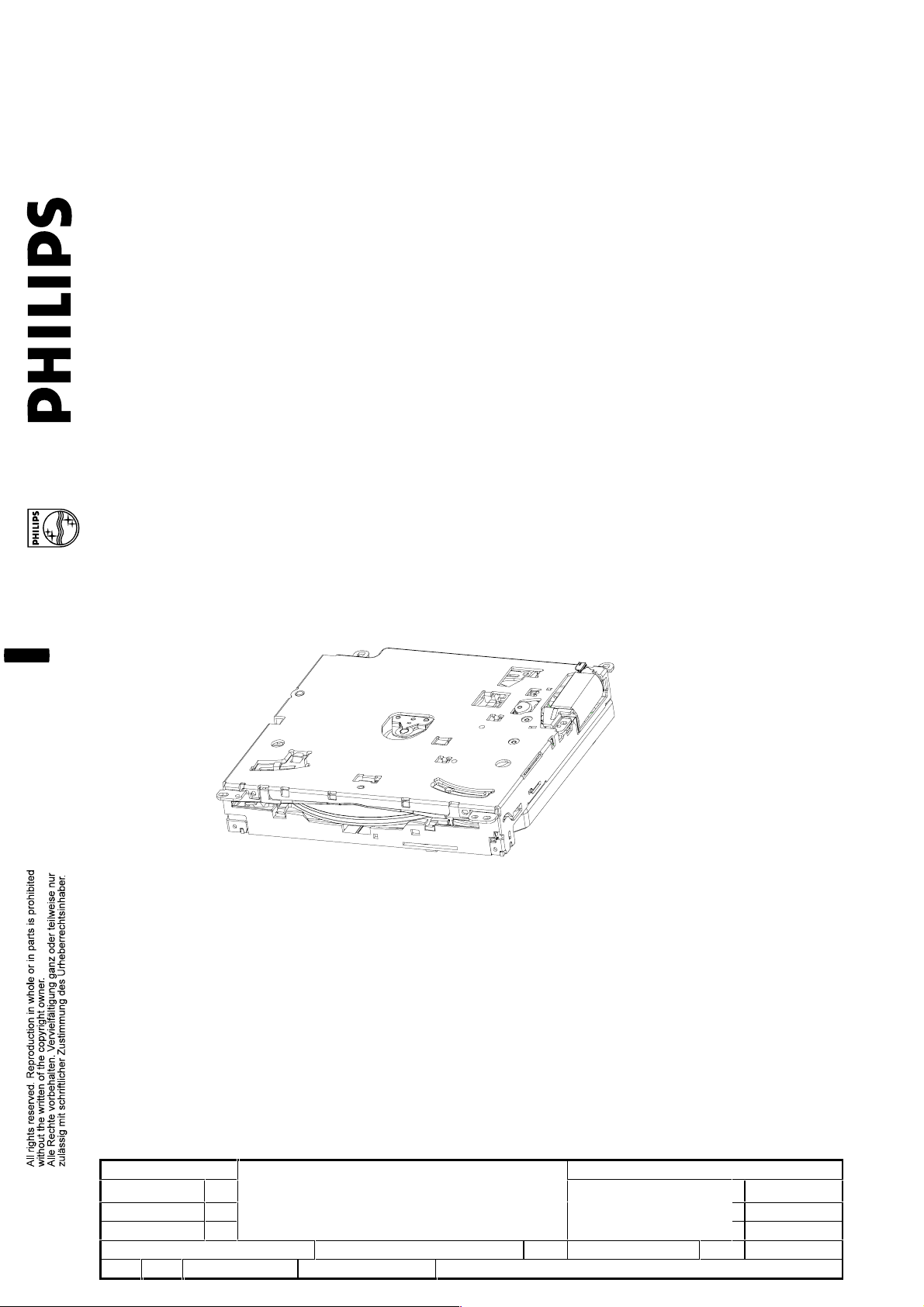
DVD-V3 4.2/1
DIGITAL VERSATILE DISC VIDEO MODULE
FLEXILOADER
Edition 1.0
2002-08-02 3
Name: A. Villar Supers. -------------- 20 10 – 591 - 1 A4
WU Check Date 2000-03-03 PROPERTY OF AUTOMOTIVE PLAYBACK MODULES
Module assy 9307 006 30404
DVD-V3 4.2/1
SPECIFICATION
Page 2
TABLE OF CONTENTS
1 REVISION HISTORY.....................................................................................................................................................3
2 APPLICABLE DOCUMENTS.......................................................................................................................................3
3 FEATURES......................................................................................................................................................................4
3.1 M
3.2 P
3.3 P
3.4 I
3.5 I
3.6 M
3.7 V
ECHANISM...............................................................................................................................................................4
IROUETTE LOAD IN G ..................................................................................................................................................4
ROTECTIONS .............................................................................................................................................................4
NTEGRATED PWB .....................................................................................................................................................4
NTERFACE .................................................................................................................................................................4
ULTIREAD...............................................................................................................................................................4
IDEO SE TTINGS.........................................................................................................................................................4
4 GENERAL SPECIFICATION........................................................................................................................................5
4.1 G
4.2 M
4.3 D
4.4 L
ENERAL CONDITIONS ...............................................................................................................................................5
EASURING CONDITIONS ...........................................................................................................................................5
ISC MEDIA ...............................................................................................................................................................5
ASER CLASS .............................................................................................................................................................5
5 ME CHAN ICAL PERFORMANCE ................................................................................................................................6
5.1 O
5.2 O
5.3 A
5.4 O
5.5 M
5.6 W
5.7 M
6 VIBRATION PERFORMANCE.....................................................................................................................................8
6.1 G
6.2 R
7 PLAYABILITY PERFORMANCE.................................................................................................................................9
7.1 DVD ..........................................................................................................................................................................9
7.2 C
8 ELECTRICAL SPECIFIC AT ION ................................................................................................................................10
8.1 M
8.2 P
8.3 C
8.4 O
PERATING TEMPERATURE.........................................................................................................................................6
PERATING ANGLE.....................................................................................................................................................6
CCESS TIME..............................................................................................................................................................6
PERATING FORCES....................................................................................................................................................7
ECHANICAL NOISE ................................................................................................................................................... 7
EIGHT......................................................................................................................................................................7
ECHANICAL DIMENSIONS.........................................................................................................................................7
ENERAL CONDITIONS ...............................................................................................................................................8
ANDOM VIBRATION SPECIFICATION.........................................................................................................................8
OMPACT DISC...........................................................................................................................................................9
ODULE CONNECTION.............................................................................................................................................10
OWER SUPPLY.........................................................................................................................................................11
ONTROL – INTERFACE ............................................................................................................................................12
UTPUTS ..................................................................................................................................................................13
9 TESTING .......................................................................................................................................................................15
9.1 L
9.2 E
9.3 E
IFE..........................................................................................................................................................................15
NDURANCE TEST.....................................................................................................................................................15
NVIRONMENTAL TESTS...........................................................................................................................................15
9.4 EMC ........................................................................................................................................................................16
9.5 E
LECTROSTATIC DISCHARGE....................................................................................................................................17
10 SW CONTROL / FUNCTIONS ...............................................................................................................................17
11 APPLICATION CIRCUITRY ...................................................................................................................................18
12 DESCRIPTION FOR HANDLING AND MOUNTING..........................................................................................19
2002-08-02 3
DVD-V3 4.2/1
SPECIFICATION
Module assy 9307 006 30404
Name: A. Villar Supers. -------------- 20 10 – 591 - 2 A4
WU Check Date 2000-03-03 PROPERTY OF AUTOMOTIVE PLAYBACK MODULES
Page 3
1 REVISION HISTORY
Version Date Change description Status Changes are
0.1 2000-03-03 First issue DRAFT
0.2 2000-05-18 Update after review DRAFT
0.3 2001-01-16 Changed to DVD-V3 4.2 and
reviewed
0.4 2001-03-02 Update; connectors changed DRAFT
0.5 2001-03-12 Change video connector type DRAFT Ì (A)
0.6 2001-06-13 Update DRAFT Ì (B)
0.7 2001-11-26 Update DRAFT Ì (C)
0.8 2002-04-17 Update (e.g. EMC, DVD V3
4.2/1 and CD Text added)
1.0 2002-08-22 Released after review Ì (E)
DRAFT
DRAFT Ì (D)
marked with
2 APPLICABLE DOCUMENTS
[1] Mechanical Specification DVD-V3 12NC = 9307 006 30404 sheet 191
[2] CIS - Communication Interface Specification 12NC = 3312-907-0015 sheet 193
[3] Application Note & FAQ Version 1.0 – 2001-10-17 ( Author : Chris Bender )
[4] Recommendation ITU-R BT.470-5 - Conventional Television Systems
[5] Philips Semiconductors - “The I2C-bus specification”, Version 2.1, Jan. 2001
[6] Philips Semiconductors - “I2S bus specification”, revision 1996 June 5
[7] Digital audio Interface, Reference number = CIE/IEC 958; 1989
[8] Digital audio – Interface for non-linear PCM encoded audio bitstreams applying IEC 60958
Reference number = CIE/IEC 61937 : 2000
2002-08-02 3
Name: A. Villar Supers. -------------- 20 10 – 591 - 3 A4
WU Check Date 2000-03-03 PROPERTY OF AUTOMOTIVE PLAYBACK MODULES
Module assy 9307 006 30404
DVD-V3 4.2/1
SPECIFICATION
Page 4
3 FEATURES
3.1 Mechanism
• Slim dimensional DVD mechanism
• Operates at any mounting angle
• Disc loading motorised
• Electronic anti-vibration servo system for excellent
vibration performance
• Optical Pick-up drive for DVD and CD compatibility
3.2 Pirouette loading
• Scratch free loading/ejecting system
3.3 Protections
• 2nd disc insertion protection
3.4 Integrated PWB
3.5 Interface
• 8 cm disc protection
• DVD / CD Frontend Decoder and Servo controller
• DVD Backend Decoder with Host processor
• Shock memory
• Temperature detection
• 8 V / 3,3 V power supply
• CVBS Video output
• Y/C (S-Video) output
• RGB Video output + CS
• I²S bus digital audio output
• S/P-DIF digital audio output
• I²C bus control interface
3.6 MultiRead
• Capability to read
• DVD-Video (single/dual layer)
• DVD-Recordable
• VIDEO CD
• CD-DigitalAudio
• CD-Recordable
• CD ReWritable
• MP 3 Playback
• CD Text Ì (D)
3.7 Video settings
• APM standard settings (Background, region code...)
2002-08-02 3
Name: A. Villar Supers. -------------- 20 10 – 591 - 4 A4
WU Check Date 2000-03-03 PROPERTY OF AUTOMOTIVE PLAYBACK MODULES
Module assy 9307 006 30404
DVD-V3 4.2/1
can be reprogrammed at customer with CD-ROM
SPECIFICATION
Page 5

4 GENERAL SPECIFICATION
4.1 General conditions
This document specifies the performance and reliability of the DVD-V3 4.2 module used with DVD discs
only, unless otherwise stated.
The Specification refers to the following documents:
• Communication Interface Specification DVD-V3 (sheet 193)
• Mechanical drawing module assembly (sheet 191)
• Application Notes
The specification values are guaranteed at the module level, e.g. connectors.
4.2 Measuring conditions
according IEC 68-1 part 5.3
standard conditions at module unless otherwise stated:
• temperature 15°C ≤ RT (Room Temperature) ≤ to 35°C
• rel. humidity 45% to 75%
• air pressure 860 mbar to 1060 mbar
• mounting horizontal (left/right and front/rear)
• rated voltage V1=8 V power
V2=3.3 V digital
DVD single layer: PHILIPS CVP 02.19, 12NC 7104 099 97871
CD-Audio: PHILIPS APM Testdisc, 12NC 7112 235 1402
The test discs have to be clean and undamaged.
4.3 Disc Media
• Test-discs:
• measurements are conducted at default SW settings
• DVD-VIDEO according DVD Specifications for Read-Only Disc:
- Part 1 : Physical Specifications
- Part 2 : File System Specifications
- Part 3 : Video Specifications
- Single/double layer and single/double sided
- region code can be selected
• DVD-Recordable 3.95GB according DVD-R Specification 1.0
• VIDEO CD according Video CD Specification 2.0
• CD-DA according IEC 908 (Red Book)
• CD-ROM according ISO/IEC 10148 (Yellow Book)
• CD-R / RW according Orange Book Part 2/3
• 12 cm disc; 8 cm disc with adapter only
4.4 Laser Class
Laser ‘class 1’ according DIN EN 60825-1
2002-08-02 3
Name: A. Villar Supers. -------------- 20 10 – 591 - 5 A4
WU Check Date 2000-03-03 PROPERTY OF AUTOMOTIVE PLAYBACK MODULES
Module assy 9307 006 30404
DVD-V3 4.2/1
SPECIFICATION
Page 6
5 MECHANICAL PERFORMANCE
5.1 Operating temperature
Operating range: − 20°C to + 70°C
Functional ( load, eject, play ): − 30°C to + 85°C
Storage ( non operating ): − 40°C to + 90°C
Remark:
A degradation of lifetime of the laser-diode must be taken into account, when operating in temperatures
higher than +70°C. Temperature sensor detects 85°C.
5.2 Operating angle
The DVD module can operate at any operating angle
5.3 Access time
Remark: Access times are dependant on disc and data content
5.3.1 DVD
typ. max unit
Load to Play 16 19 s
Start up from stop 6 9 s
5.3.2 CD-Audio
max unit Ì (D)
Load to Play 21 s
Start up from stop 9 s
5.3.3 Mechanical Transition
max unit
Eject from Play 9 s
2002-08-02 3
Name: A. Villar Supers. -------------- 20 10 – 591 - 6 A4
WU Check Date 2000-03-03 PROPERTY OF AUTOMOTIVE PLAYBACK MODULES
Module assy 9307 006 30404
DVD-V3 4.2/1
SPECIFICATION
Page 7

121
31 138
x y
5.4 Operating forces
min typ max. unit
Insertion force
movement into loading -- 3 6 N
Withdrawal force
remove DVD 1 2 4 N
Pushback force -- -- 14 N Ì (C)
from Eject position
Eject transition force 0.5 -- -- N Ì (C)
valid with CD in Eject transition
between 10 mm from play position
till eject/ end position.
5.5 Mechanical noise
Philips method of measurement UAN-L 1059 ( measured at 10 cm above disc enter ).
Module mounted on pins standing on rubber foam. Use clean and undamaged test-disc.
Play DVD : < 49 dBA Ì (E)
Play CD-DA : < 46 dBA
Trackjump CD-DA (Tr.1 <-> Tr.2) : < 48 dBA
Trackjump CD-DA (Tr.1 <-> Tr.20) : < 56 dBA
Testdiscs : DVD = A-BEX TDV-510
CD = Philips SBC-444
Eject-Media : < 70 dBA
5.6 Weight
module only : typ. 550 g
Mechanical dimensions
5.7
Ì (C)
For all details see ‘mechanical drawing’ of module (sheet 191).
2002-08-02 3
Name: A. Villar Supers. -------------- 20 10 – 591 - 7 A4
WU Check Date 2000-03-03 PROPERTY OF AUTOMOTIVE PLAYBACK MODULES
z
DVD-V3 4.2/1
SPECIFICATION
Module assy 9307 006 30404
Page 8

6 VIBRATION PERFORMANCE
6.1 General conditions
Acceptance criteria: no audible interruption and
no user perceivable video failures
Directions: ( x,y,z )
Measurement: acc. 4.2 (measuring conditions)
Equipment: no influence to the performance of the module
6.2 Random Vibration Specification
Playback time: each 60 s
Power spectral density profiles; reference 0dB:
y-direction (longitudinal) x-direction (lateral) z-direction (vertical)
level: target 0.835g
frequ. (Hz) density g²/Hz frequ. (Hz) density g²/Hz frequ. (Hz) density g²/Hz
10 .00425 10 .00960 10 .02110
15 .01610 15 .03700 32 .03000
22 .03600 25 .00670 60 .00500
37 .01100 37 .01100 125 .00006
235 .00002 85 .00180 170 .00042
285 .00004 185 .00001 330 .00001
785 .000001 217 .00006 385 .00002
1000 .000004 295 .000001 1000 .000001
635 .000006
1000 .000001
level: target 0.79g
RMS
level: target 1.009g
RMS
RMS
2002-08-02 3
DVD-V3 4.2/1
SPECIFICATION
Module assy 9307 006 30404
Name: A. Villar Supers. -------------- 20 10 – 591 - 8 A4
WU Check Date 2000-03-03 PROPERTY OF AUTOMOTIVE PLAYBACK MODULES
Page 9

7 PLAYABILITY PERFORMANCE
7.1 DVD
Acceptance criteria: no audible mute and
no user perceivable video failures
Test-disc: see below
min typ unit
Black dot
ABEX TDV-525 800 --- µm
Simulated fingerprint
ABEX TDV-525 65 --- µm
White scratch
ABEX TDV-521 800 1000 µm
Vertical Deviation
ABEX TDV-531 0.4 --- mm Ì (C)
Eccentricity
ABEX TDV-512 100 --- µm
7.2 Compact Disc
Acceptance criteria: no audible mute
Test-disc: see below
min typ unit
Black dot
Philips SBC 444A 800 -- µm
Simulated fingerprint
Philips SBC 444A 70 -- µm
White scratch
ABEX TCD 721R 800 -- µm Ì (C)
Vertical Deviation
ABEX TCD 731RA 0.81 --- mm Ì (C)
Eccentricity
Philips Test CD 150 150 --- µm Ì (C)
2002-08-02 3
Name: A. Villar Supers. -------------- 20 10 – 591 - 9 A4
WU Check Date 2000-03-03 PROPERTY OF AUTOMOTIVE PLAYBACK MODULES
Module assy 9307 006 30404
DVD-V3 4.2/1
SPECIFICATION
Page 10

8 ELECTRICAL SPECIFICATION
8.1 Module Connection
Pin_1 of Pos 1405
( 26 Pin – Video )
Pin_1 of 1306
( 8 Pin Power )
8.1.1 Connectortypes and pinning Ì (E)
PWB- Pos 1405 (26 Pin – Video Bottom Contact ) PWB- Pos 1306 (Power)
1
SPDIF
2
GND
3
PCM_SCLK
4
PCM_DATA_2
5
PCM_WCLK
6
PCM_DATA_1
7
PCM_DATA_0
8
GND
9
RESET
10
CRQ
11
SCL
12
SDA
13
Video GND
14
CVBSt
15
Video GND
16
B
17
Video GND
18
G
19
Video GND
20
R
21
Video GND
22
CS
23
Video GND
24
Y
25
Video GND
26
C
Type : Molex 52689-2693 for V3-4.2/1
S/P-DIF digital audio output
Digital ground
IIS bus Bitclock
Digital Audio Out
IIS bus Data 2
IIS bus Wordclock
IIS bus Data 1
IIS bus Data 0
Digital ground
Reset
IIC bus request
2
C-BUS
I
IIC bus SCL
IIC bus SDA
Video ground
CVBS Video output
Video ground
BLUE
Video ground
GREEN
Video ground
Composite Video:
= 75 Ohm
RGB_Video:
R,G,B = 75 Ohm
CS = 3.3V digital signal
RED
Video ground
Composite Sync
Video ground
Luma
Video ground
S-Video :
= 75 Ohm
Croma
Type : Molex 53261-0890
SENS_I
1
TEMP
2
+8V
3
PGND (correspond.
4
to +8V)
+3.3 V
5
+3.3V
6
GND (correspond.
7
to +3.3V)
8
GND (correspond.
to +3.3V)
2002-08-02 3
DVD-V3 4.2/1
SPECIFICATION
Module assy 9307 006 30404
Name: A. Villar Supers. -------------- 20 10 – 591 - 10 A4
WU Check Date 2000-03-03 PROPERTY OF AUTOMOTIVE PLAYBACK MODULES
Page 11

8.2 Power supply
8.2.1 Voltage
Description
V1 (power)
Ripple voltage V1
(10Hz – 50kHz)
V2 (digital)
Ripple voltage V2
(10Hz – 50kHz)
V2 rising at power up 0.5 -- -- V/ms
Ì (C)
8.2.2 Currents
8.2.2.1 V1
Description
Play-mode 400 500 mA
Peak (t < 10 ms) 1150 1650 mA
Peak (t < 2 s) 1000 1200 mA
Vibration rms 750 -- mA
Ì (D)
8.2.2.2 V2
Ì (D)
Standby (Reset active)
Description
Play-mode 1300 1500 mA
Stop-mode 1200 1400 mA
Standby (Reset active) 600 850 mA
Min. Typ. Max. unit
7,5 8 8,5 V
-- -- 200 mVpp
3,1 3,3 3,5 V
-- -- 50 mVpp
Typ. Max. unit
100 150 mA
Typ. Max. unit
2002-08-02 3
Name: A. Villar Supers. -------------- 20 10 – 591 - 11 A4
WU Check Date 2000-03-03 PROPERTY OF AUTOMOTIVE PLAYBACK MODULES
Module assy 9307 006 30404
DVD-V3 4.2/1
SPECIFICATION
Page 12

8.3 Control – Interface
Ì (C)
8.3.1 I²C-Interface
8.3.1.1 SDA,SCL
min. typ. max. unit
input voltage high 2.4 V2 V
input voltage low 0 0.6 V
output voltage low ( 1,2 mA ) 0.4 V
internal pullup to 3.3V - 2.7 - kΩ
Further Parameters are specified in [5] “The I2C-bus specification” chapter 15, Standard Mode.
8.3.1.2 CRQ
input min. typ. max. unit
input voltage high 2.7 V2 V
input voltage low 0 0.5 V
CRQ low time see CIS [2]
Rise and fall time - - 250 ns
internal pullup to 3.3V 9 10 11 kΩ
8.3.2 Additional Interface lines
8.3.2.1 RESET
min. typ. max. unit
voltage high 3 - V2 V
voltage low 0 - 0.5 V
reset low time 15 - ∞ ms
internal pullup to 3.3V 7 10 13 kΩ
8.3.2.2 Insertswitch SENS_I
The insert switch is applicable at the connector as "SENS_I" to indicate an insert operation. This can be used in
case the power is switched off and the system needs to wake up as well as to indicate that a disc is removed
after an eject operation.
- Switch closes to ground and is directly connected to the SENS_I-line.
No disc
SENSE_I
=
insert_sw
Eject
closed
Loading
Ejecting
Stop- Position
- To use this switch externally, it is required to connect a pull-up-resistor to the SENS_I line.
min. max. unit
switch-open voltage - V2+0.25 V
switch closed R
- 50 Ω
i
Current through switch - 10 mA
2002-08-02 3
DVD-V3 4.2/1
SPECIFICATION
Module assy 9307 006 30404
Name: A. Villar Supers. -------------- 20 10 – 591 - 12 A4
WU Check Date 2000-03-03 PROPERTY OF AUTOMOTIVE PLAYBACK MODULES
Page 13

8.3.2.3 Temperature warning TEMP
This is a tri-state-output of the µC. With RESET=low it has high impedance. See also [2 ] -> CIS
min. max. unit
output voltage high (-1mA) 2.8 V2 V
output voltage low (+1mA) - 0.4 V
tri-state leakage current -10 10 µA
(0....3.3V)
8.4 Outputs
Ì (C)
8.4.1 Video (CVBS, S-Video, RGB)
All video outputs are analog outputs with dc-coupling and an output impedance of 75Ω. To ensure good signal
performance the outputs should be matched with 75Ω. Under this condition 100 units [4] = 0.7Vpp
8.4.1.1 CVBS
The CVBS signal is an analog video signal containing luminance and chrominance information. Definitions of the
signal are described in ITU recommendation ITU-R BT.470-5 [4].
The following CVBS signals are possible:
M / NTSC 525 lines 59.94Hz 3.579545MHz∗(1±100ppm) NTSC
B,G / PAL 625 lines 50Hz 4.43 361 8MH z∗(1±100ppm) PAL
M / PAL 525 lines 59.94Hz 3.575611MHz∗(1±100ppm) PAL
PAL60 525 lines 59.94Hz 4.433618MHz∗(1±100ppm) PAL
The CVBS signal depends on the DVD, the version-table (especially the region code) of the module and on
software settings.
For example a DVD produced for the United States (region code 1) brings a M / NTSC-signal to the CVBS
output.
8.4.1.2 S-Video
The S-Video signal is similar to the CVBS signal described before, with the luminance (Y) and the chrominance
(C) information divided to separate lines. Color coding in the chrominance signal is done by the same principle
than NTSC or PAL with a quadrature modulation. The S-Video signal eliminates the cross luminance- and cross
color-distortion and is a higher quality video signal than CVBS.
The parameters of the S-Video signal are also described in ITU-R BT.470-5 [4] and other ITU
recommendations.
8.4.1.3 RGB
The RGB signal is an analog video signal with 3 separate colors. Red, Green and Blue are the basic colors of a
television tube or a TFT-Display. With RGB, the color decoding in the display unit (either a TV or a TFT) isn’t
necessary furthermore. This prevents distortion caused by the color coding and decoding and may save display
cost. The RGB signal is the video output with the highest quality level. The RGB signal needs four lines, one for
each color and one for the synchronization. The synchronization can either be done with the CVBS-signal or with
the digital Composite Sync signal and depends on the display device. The basic parameters (number of lines,
signal levels, fields per second, interleaving etc.) for each of the 3 signals are the same than a CVBS signal
without color and sync information. With that the parameters of the R-, G- and B-signal are also described in
ITU-R BT.470-5 [4] and other ITU recommendations.
Note: The RGB signal is not compliant to the RGB signal used in computer monitors, because computer
monitors need progressive scan (non interleaved) and separate H- and V-Sync signals.
2002-08-02 3
Name: A. Villar Supers. -------------- 20 10 – 591 - 13 A4
WU Check Date 2000-03-03 PROPERTY OF AUTOMOTIVE PLAYBACK MODULES
Module assy 9307 006 30404
DVD-V3 4.2/1
SPECIFICATION
Page 14

8.4.1.4 Composite Sync CS
The CS signal is a digital TTL level synchronization signal that contains the horizontal and the vertical
synchronization information. It can be used with some TFT Displays in RGB Mode, while other TFT’s and TVMonitors use the CVBS for synchronization.
min. max. unit
output voltage high (-1mA) 2.75 V2 V
output voltage low (1mA) - 0.32 V
8.4.2 Digital Audio I²S (PCM_SCLK, PCM_WCLK, PCM_DATA0...PCM_DATA2)
The module is the I²S transmitter and works as a master.
typ.
SCLK period T (CD-audio) 354 ns
(CD-video)
SCLK period T (DVD) 325 ns
Further Parameters are specified in the “I2S bus specification” [6].
8.4.3 Digital Audio SPDIF
S(ony)P(hilips)DIF is a digital audio format which can have 2 different output formats.
In one case the SPDIF signal contains a linear PCM coded stereo signal with all the information (Clock, Data) in
one signal and can be decoded with a SPDIF-DAC. ( see IEC958 [7] )
In the other case, the SPDIF signal contains Multichannel digital audio (Dolby Digital, AC3). The signal is then a
nonlinear PCM Datastream with MPEG coding and needs a MPEG-Decoder for decoding. ( see IEC61937 [8] )
min. max. unit
output voltage high (-1mA) 2.4 -- V
output voltage low (+1mA) 0 0.4 V
input capacitance 10 pF
Further details are specified in IEC958 [7] for PCM and IEC61937 [8] for MPEG.
2002-08-02 3
Name: A. Villar Supers. -------------- 20 10 – 591 - 14 A4
WU Check Date 2000-03-03 PROPERTY OF AUTOMOTIVE PLAYBACK MODULES
Module assy 9307 006 30404
DVD-V3 4.2/1
SPECIFICATION
Page 15

9 TESTING
9.1 Life
Continious play : min. 1500 hrs / 55°C
min. 2000 hrs / 55°C / (B10)
9.2 Endurance test
Number of operations for :
Insert, Play, Search, Standb y and Eject min. 15,000 cycles
Random jumps (1/3 long; 2/3 short) min. 2,000,000 jumps
9.3 Environmental tests
9.3.1 General conditions
Check: Measurement and functional checks before and after test.
Mounting: The module is tested without disc and mounted on a rigid test fixture on its
mounting points acc. mechanical drawing sheet 191
Fixture: The resonance frequency shall exceed 500 Hz.
Operation: Non operating in eject position without disc
Accelaration Given in peak value unless otherwise stated
9.3.2 Sine vibration short period
IEC 68-2-6 Test Fc 20 min each direction
frequency 10 - 60 - 10 Hz, acceleration 3 g constant (sine sweep time 1 octave/min), 3 directions
9.3.3 Mechanical shock
IEC 68-2-27 Test Ea 70 g for 11 ms
pulse, half sine, one shock each 6 directions, deck fixed on rigid plate
9.3.4 Storage
IEC 68-2-Ab 96 hrs - 40°C
IEC 68-2-Bb 96 hrs + 90°C
9.3.5 Cyclic humidity
IEC 68-2-30 Db 21 cycles: 12 hrs + 40°C and 93% RH
(Module is powered 1 hr in every cycle) and 12 hrs + 25°C and 98 % RH
9.3.6 Temperature shock
IEC 68-2-14 Na 100 cycles: 30 min - 40 °C
30 min + 85 °C
changing time < 10 sec.
2002-08-02 3
Name: A. Villar Supers. -------------- 20 10 – 591 - 15 A4
WU Check Date 2000-03-03 PROPERTY OF AUTOMOTIVE PLAYBACK MODULES
Module assy 9307 006 30404
DVD-V3 4.2/1
SPECIFICATION
Page 16

9.4 EMC
9.4.1 General conditions Ì (E)
Testsetup : according WUR74-01TEST-022 – horizontal and vertical
Test CD: A-BEX TDV510
Test-Mode: DVD-V3 DVD-Datareading without 26 pin FFC
9.4.2 Free field narrow-band radiated emission
Limits for narrow-band radiated emission (peak detector)
Measurement in accordance with CISPR25 free field method (anechoic chamber 1m distance).
Frequency
[MHz]
Radiated emission
limit
[dBuV/m]
0,15 – 30 30 ---------------------- ----
30 – 700 20 --------------------------
Remark
700-1100 30 -------------------------1100-1400 40 -------------------------1400-2000 30 --------------------------
325-375 40 OPU-Fundamental ( single spike ! )
650-750 40 OPU-1 Harmonic ( single spike ! )
975-1125 40 OPU-2 Harmonic ( single spike ! )
1300-1500 40 OPU-3 Harmonic ( single spike ! )
1625-2250 40 OPU-4 /5 Harmonic ( 2 spikes ! )
dBµV/m
45
40
35
30
25
20
15
DVD-V3 EMC P erformance ( DVD -reading without 26-pin FFC )
Testsetup according CISPR25
OPU-RF- Modulation*
10
5
0
100 kHz
1MHz
DVD-V3 4.2/1
10 MHz
Frequency
100 MHz
SPECIFICATION
1 GHz
Module assy 9307 006 30404
2002-08-02 3
2GHz
Name: A. Villar Supers. -------------- 20 10 – 591 - 16 A4
WU Check Date 2000-03-03 PROPERTY OF AUTOMOTIVE PLAYBACK MODULES
Page 17

9.5 Electrostatic discharge
According the ESD test description WUR74-02TEST-003 Ì (D)
Parts accessible to the End – User +/-5kV, 150pF/330DLUGLVFKDUJH no malfunction
( complete radio / navigation application ) +/-15kV, 150pF/330DLUGLVFKDUJH no hang-ups
Parts not accessible to End – User +/-5kV, 150pF/330FRQWDFWGLVFKDUJH no malfunction
10 SW CONTROL / FUNCTIONS
See CIS [2]
The player is controlled via IIC bus in which it is the master.
Depending on the inserted disc, following functions and features are possible:
Player Functions: Play
Stop
Pause / Still
Next
Previous
Step forward
Fast Forward (4, 32)
Reverse (4, 32)
Slow Forward (1/2,1/4, 1/8)
Reverse (1/2,1/4, 1/8)
Shuffle
Scan
Repeat Chapter
Title
Disc
Track
AB Repeat
Parental Control Disc Lock
DVD
Step backward
2002-08-02 3
Name: A. Villar Supers. -------------- 20 10 – 591 - 17 A4
WU Check Date 2000-03-03 PROPERTY OF AUTOMOTIVE PLAYBACK MODULES
Module assy 9307 006 30404
DVD-V3 4.2/1
SPECIFICATION
Page 18

mechanism
Frontend Decoder
DVD / CD Backend
Decoder with Host
8V (1,2A)
IIS
S-Video (Y/C)
CVBS
SCL
Insert
11 APPLICATION CIRCUITRY
Loader
driver
Servo
driver
Diode
Amp.
DVD / CD
and
Servo Controller
Temp
switch
Processor
Reset
SDA
S/P-DIF
VGND
Power
supply
PGND
3,3V (1,5A)
DGND
DVD-V3 4.2/1
Module assy 9307 006 30404
2002-08-02 3
SPECIFICATION
Name: A. Villar Supers. -------------- 20 10 – 591 - 18 A4
WU Check Date 2000-03-03 PROPERTY OF AUTOMOTIVE PLAYBACK MODULES
Page 19

12 DESCRIPTION FOR HANDLING AND MOUNTING
1. The DVD - Module will be packed ESD protected.
2. Transport the DVD - Module always without medium.
The connectors (Module PWB, wire treatment and the flex foil) have to be in their defined position.
3. Handle the DVD - Module always carefully and don’t bring it in contact with dust, oil, grease or other
contamination.
4. Parts which are added by the customer (e.g. print holders, wire holders, etc.) has to be released by Philips
APM Wetzlar. Furthermore these parts should not hinder moving parts of the mechanism.
5. During transport, handling and mounting, the DVD - Module must be protected against Electro Static
Discharge (ESD). The radio and the user must be grounded.
6. Connection to the radio only in power off mode.
7. The screws for mounting the DVD - Module into the set have to be screwed in according the order given in
the mechanical drawing. The tabs of the modules should not be damaged during screwing.
8. The cable routing has to be in such a way, that no moving parts of the module are touched or blocked.
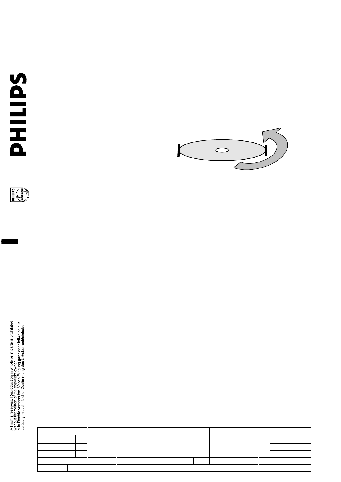
9. Hold the Module as it is shown in the sketch below ( ESD-protection is required ).
2002-08-02 3
Name: A. Villar Supers. -------------- 20 10 – 591 - 19 A4
WU Check Date 2000-03-03 PROPERTY OF AUTOMOTIVE PLAYBACK MODULES
Module assy 9307 006 30404
DVD-V3 4.2/1
SPECIFICATION
Page 20

50N
Alternative 1:
Hold the Module front and rear ( ESD-protection is required ) . Max. force 50N
max
Alternative 2:
(ESD-protection is required).
Hold the Module between EMC-shield and Topcover to grab it out of the packging
2002-08-02 3
Name: A. Villar Supers. -------------- 20 10 – 591 - 20 A4
WU Check Date 2000-03-03 PROPERTY OF AUTOMOTIVE PLAYBACK MODULES
Module assy 9307 006 30404
DVD-V3 4.2/1
SPECIFICATION
 Loading...