

Page 1
MY500 JetPrinter™
P-030-0014-EN
Service Manual
English
®
For a fast changing world
Page 2

Page 3

MYDATA MY500 JetPrinter Preface
MY500 JetPrinter™
Service Manual
English
P-030-0014-EN – Service Manual Rev. 0003 2008-06 i
Page 4
Preface MY500 JetPrinter MYDATA
This document is intended for the MY500 JetPrinter running any version of the software.
A standard system and available optionals are covered by this document. Depending on your system configuration you may lack
some of the features mentioned in the document.
Disclaimer
Hardware and software mentioned in this document are subjected to continuous development and improvement. Consequently,
there may be minor discrepancies between the information in the document and the performance or design of the product.
Specifications, dimensions and other statements mentioned in this document are subject to changes without prior notice.
Federal Communications Commission (FCC)
This equipment has been tested and found to comply with the limits for a Class A digital device, pursuant to part 15 of the FCC
Rules. These limits are designed to provide reasonable protection agains t harmful interference when the equipment is operated in a
commercial environment. This equipment generates, uses, and can radiate radio frequency energy and, if no t installed and used in
accordance with the instruction manual, may cause harmful interference to radio communications. Operation of this equipment in
a residential area is likely to cause harmful interference in which case the user will be required to correct the inte rference at his own
expense.
Do not start, operate or service the
machine until you have read and
understood the safety chapter.
MYDATA and its suppliers shall not be liable for any damages related to this software or hardware, or for any other damages whatsoever caused by the use of or inability
to use any MYDATA product. This is applicable even if MYDATA has been advised of the damage risk. Under any circumstances, MYDATA’s entire liability shall be
JetPrint, MYPlan, SYS2.9, TEX, TMFlex, TRAYWagon Magazine, TUBEFork, and YWagon are trademarks of MYDATA automation AB. TPSys, Agilis, HYDRA
SpeedMount, MYLink, and TM8 are registered trademarks of MYDATA automation AB. The MY... and TP... machine names are either trademarks or registered
trademarks of MYDATA automation AB. DOS is a trademark of Microsoft Corporation. Microsoft, Microsoft Windows and Microsoft Access are registered trademarks
of Microsoft Corporation. Other trademarks mentioned in this document are trademarks or registered trademarks of their respective owners.
limited to replace such defective software or hardware that was originally purchased from MYDATA.
MYDATA automation AB, Box 20155, S-161 02 Bromma, Sweden.
Phone +46 8 475 55 00 – Fax +46 8 475 55 01 – Internet www.mydata.com
This document or parts of it may not be reproduced without a written permission of MYDATA automation AB.
Infringements will be prosecuted. All rights reserved.
Copyright © MYDATA automation AB, Sweden, 1990–2008.
ii Rev. 0003 2008-06 P-030-0014-EN – Service Manual
Page 5

MYDATA MY500 JetPrinter Preface
Table of Contents
Text Conventions ......................................................................................................... vi
Danger, Warning, Caution, and Note ................................................................ vi
Italic Font ......................................................................................................... vii
Bold Font ......................................................................................................... vii
Menu Selections ............................................................................................... vii
Lists .................................................................................................................. vii
1. Safety ........................................................................................................................ 1-1
Emergency Stop Buttons .................................................................................... 1-2
Emergency Movement of Machine Elements .................................................... 1-3
Safety Hoods and Devices ................................................................................. 1-3
Warning Signs .................................................................................................... 1-4
Fast Moving Machinery ................................................................................ 1-4
Dangerous Voltage ....................................................................................... 1-6
Laser Classification ...................................................................................... 1-7
Magnetic Fields ............................................................................................ 1-8
Type Plate .......................................................................................................... 1-9
Noise .................................................................................................................. 1-9
Equipment Precautions ...................................................................................... 1-10
Magnetic Fields ............................................................................................ 1-10
Compressed Air ............................................................................ ..................... 1-11
Solder Paste, Glue and Conditioner ................................................................... 1-11
Waste Disposal ............................................................................................. 1-11
Material Safety Data Sheets .......................................................... ..................... 1-12
Greases .......................................................................................................... 1-12
Solder Paste .................................................................................................. 1-12
Glue ............................................................................................................... 1-12
Conditioner ................................................................................................... 1-12
In Case of Fire .................................................................................................... 1-13
ESD .................................................................................................................... 1-13
How To Help Prevent ESD ........................................................................... 1-13
2. Installation ................................................................................................................. 2-1
Site Preparation .................................................................................................. 2-2
Required Working Area ................................................................................ 2-2
Environmental Requirements ....................................................... .... ............ 2-5
Electrical Requirements ................................................................................ 2-6
Compressed Air ............................................................................................ 2-6
Transporting the Machine .................................................................................. 2-6
Installation .......................................................................................................... 2-7
Equipment ..................................................................................................... 2-7
Installation Summary .................................................................................... 2-8
Unpacking ..................................................................................................... 2-9
Lifting the Machine ...................................................................................... 2-10
Moving and Placing the Machine ................................................................. 2-12
Leveling ........................................................................................................ 2-12
Main Machine Connections ............................................................................... 2-13
Powering ............................................................................................................ 2-14
Electrical Configuration ................................................................................ 2-14
Electrical Connection .................................................................................... 2-15
Power Plug Connection ................................................................................ 2-15
Pneumatic Connection ....................................................................................... 2-16
Optional Air Cooling Unit ............................................................................ 2-17
Optional Micro Mist Separator Unit ............................................................. 2-18
Network Connection .......................................................................................... 2-19
SMEMA Connection ......................................................................................... 2-19
P-030-0014-EN – Service Manual Rev. 0003 2008-06 iii
Page 6

Preface MY500 JetPrinter MYDATA
Transport Lock ................................................................................................... 2-20
Software Installation ................................................................... ..... .... ............... 2-22
Optional Equipment ........................................................................................... 2-22
3. Machine Systems ....................................................................................................... 3-1
MY500 JetPrinter ............................................................................................... 3-1
Jet Printing .................................................................................................... 3-1
MY500 JetPrinter Main Parts ............................................................................. 3-2
Inputs and Controls ............................................................................................ 3-4
Touch Screen ................................................................................................. 3-4
Keyboard ....................................................................................................... 3-5
Trackball ........................................................................................................ 3-5
Barcode Scanner .................................................................................. .......... 3-5
Framework .......................................................................................................... 3-6
Movement Systems ............................................................................................ 3-7
The Y Beam .................................................................................................. 3-8
The X Wagon ................................................................................................ 3-9
The Cassette .................................................................................................. 3-13
Conveyor ............................................................................................................ 3-18
Manual Load Table ............................................................................................ 3-19
Machine Electronics ........................................................................................... 3-20
Block Diagrams ............................................................................................. 3-22
4. Adjustments .......................................................................... .... ................................. 4-1
System Overview ............................................................................................... 4-2
Screen Examples ................................................................................................ 4-3
5. Routine Maintenance ................................................................ ..... .... ..... ................... 5-1
Daily Maintenance ............................................................................................. 5-3
Equipment ..................................................................................................... 5-3
Cassette .......................................................................................................... 5-3
Machine ......................................................................................................... 5-4
Calibration Units ........................................................................................... 5-5
Filters ............................................................................................................. 5-6
Weekly Maintenance .......................................................................................... 5-7
Equipment ..................................................................................................... 5-7
Machine ......................................................................................................... 5-7
Others ............................................................................................................ 5-8
Monthly Maintenance ......................................................................................... 5-9
Equipment ..................................................................................................... 5-9
Machine ......................................................................................................... 5-9
Optional Refrigerated Air Dryer ................................................................... 5-9
Yearly Maintenance ........................................................................................... 5-10
Changing Calibration Paper ................................................................ ............... 5-11
Changing Waste Container ................................................................................. 5-14
Waste Disposal .............................................................................................. 5-14
Changing Cassette Ejector .................................................................................. 5-15
Lubricating X wagon Rail – 720 Operating Hours ............................................ 5-19
Testing the Safety System ............................................................... ................... 5-20
Testing the Safety Circuits ............................................................................ 5-20
Maintenance Tables ............................................................................................ 5-21
Daily Maintenance ........................................................................................ 5-21
Weekly Maintenance ..................................................................................... 5-21
Monthly Maintenance ................................................................................... 5-22
720 Operating Hours ..................................................................................... 5-22
iv Rev. 0003 2008-06 P-030-0014-EN – Service Manual
Page 7

MYDATA MY500 JetPrinter Preface
Appendix A – Specifications ...................................................... .... .............................. A-1
Appendix B – About the Documentation ..................................................................... B-1
Operator's Manual .............................................................................................. B-2
Programming Manual ........................................................................................ B-2
MYCamJP .......................................................................................................... B-2
Service Manual .................................................................................................. B-3
Spare Parts Catalog ............................................................................................ B-3
Index ............................................................................................................................... I-1
P-030-0014-EN – Service Manual Rev. 0003 2008-06 v
Page 8

Preface MY500 JetPrinter MYDATA
Text Conventions
This document uses text conventions to present information in various
situations. This is explained below.
Danger, Warning, Caution, and Note
In this document a particular text layout is used to make danger, warning, and
caution information evident. A triangular icon identifies the type of risk and
the text describes the risk.
Danger, warning, and caution information must be followed.
Assisting information, notes, have the same layout but never triangular icons.
Danger
DANGER! Danger means a potentially dangerous situation that can cause
death or severe bodily injury. The icon identifies the type of risk.
Warning
WARNING! Warning means a potentially dangerous situation that can cause
bodily injury or considerable damage to the system or equipment. The icon
identifies the type of risk.
Caution
CAUTION! Caution means that the system or equipment can be damaged or
data be lost. To distinguish caution information from warning and danger
information, this icon is always an empty triangle.
Note, example 1
A note contains any type of assisting information.
Note, example 2
One type of assisting information is tips, which normally have this icon.
vi Rev. 0003 2008-06 P-030-0014-EN – Service Manual
Page 9

MYDATA MY500 JetPrinter Preface
Italic Font
Italic font is used for software screen text (for example Parameter 1), names
(for example Spare Parts Catalog), and for warning text (described in the
previous section).
Bold Font
Bold font is used for particular important words (for example This must not
be done in reverse order).
Menu Selections
When describing software handling, menu selections are described in the
following format:
File > Page Setup > Paper Size > Portrait > OK
Lists
This example describes to open the File menu and select the Page Setup,
Paper Size, and Portrait options, and finally click the OK button.
Lists of items, points to consider, or procedures that have no relative order
appear in bulleted or hyphenated format like this:
• Item 1.
• Item 2.
or
–Item1.
–Item2.
Procedures that must be performed in a specific order appear in numbered lists
like this:
1. Perform this step first.
2. Perform this step second.
P-030-0014-EN – Service Manual Rev. 0003 2008-06 vii
Page 10

Preface MY500 JetPrinter MYDATA
viii Rev. 0003 2008-06 P-030-0014-EN – Service Manual
Page 11

MYDATA MY500 JetPrinter Safety
1. Safety
Before starting the machine, personnel involved in the machine operation,
maintenance or service must understand and follow these points:
• This machine is designed to apply solder paste and glue onto printed wiring
boards. The machine must be used excl usively for this purpose and nothing
else.
• The machine must be operated by qualified personnel only. Qualified
personnel should meet the following qualifications:
– Be above 18 years of age.
– Have no rmal depth percep tion, field of vi sion, reaction time, manual
dexterity, coordination, and no tendency to dizziness.
– Completed operators training.
• All personnel involved in machine operation must understand the use of the
emergency stop buttons. See the Emergency Stop Buttons section.
• Anyone operating this machine must obey the warning signs.
• At least one manual describing the warning signs of the particular machine
type must always be kept. For instance if the machine is upgraded to a later
version.
• An emergency stop button must be pressed down when a solder paste
cassette is manually inserted or removed.
• If there is a risk that any unauthorized personnel may alter the system
settings and thus the behavior of the machine, the logon facility for
individual access rights must be used.
• Ensure that all covers and shields are intact, mounted, and closed while the
machine is in operation.
• Do not disable or disengage any safety switch or sensor.
• Do not configure or modify MYDATA machines or devices without
consulting MYDATA. The machines, devices or the interfaces between
them might become unsafe.
• Do not use chemicals or other substances which may have any influence on
the operator or other personnel involved in the machine operation.
P-030-0014-EN – Service Manual Rev. 0003 2008-06 1 - 1
Page 12
Safety MY500 JetPrinter MYDATA
Emergency Stop Buttons
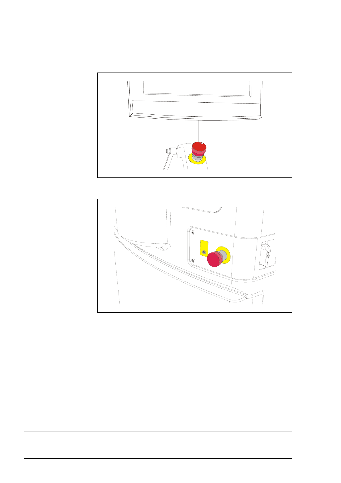
There are two red emergency stop buttons on the machine. When an
emergency stop button is pressed down, the machine will stop immediately.
Figure 1-1. Emergency stop button above the keyboard.
Figure 1-2. Emergency stop button on the machine front.
Emergency stop buttons are released by being turned clockwise.
When the front hood is lifted, a safety switch is activated and all movements
in the MY500 JetPrinter are stopped immediately.
Extra, auxiliary safety buttons can be connected at the rear of the machine.
WARNING! Always press down an emergency stop button before hands,
1 - 2 Rev. 0003 2008-06 P-030-0014-EN – Service Manual
fingers, tools, or other objects are entered within a shielded area, or if any
hoods are opened.
Test the function of emergency stop buttons at regular intervals.
Page 13
MYDATA MY500 JetPrinter Safety
Emergency Movement of Machine Elements
If an accident has occurred and an emergency movement of a machine element
is required, use the following procedure:
1. Press down an emergency stop button.
This will disconnect the motors used to position the machine elements.
2. Move the machine element away by hand.
Safety Hoods and Devices
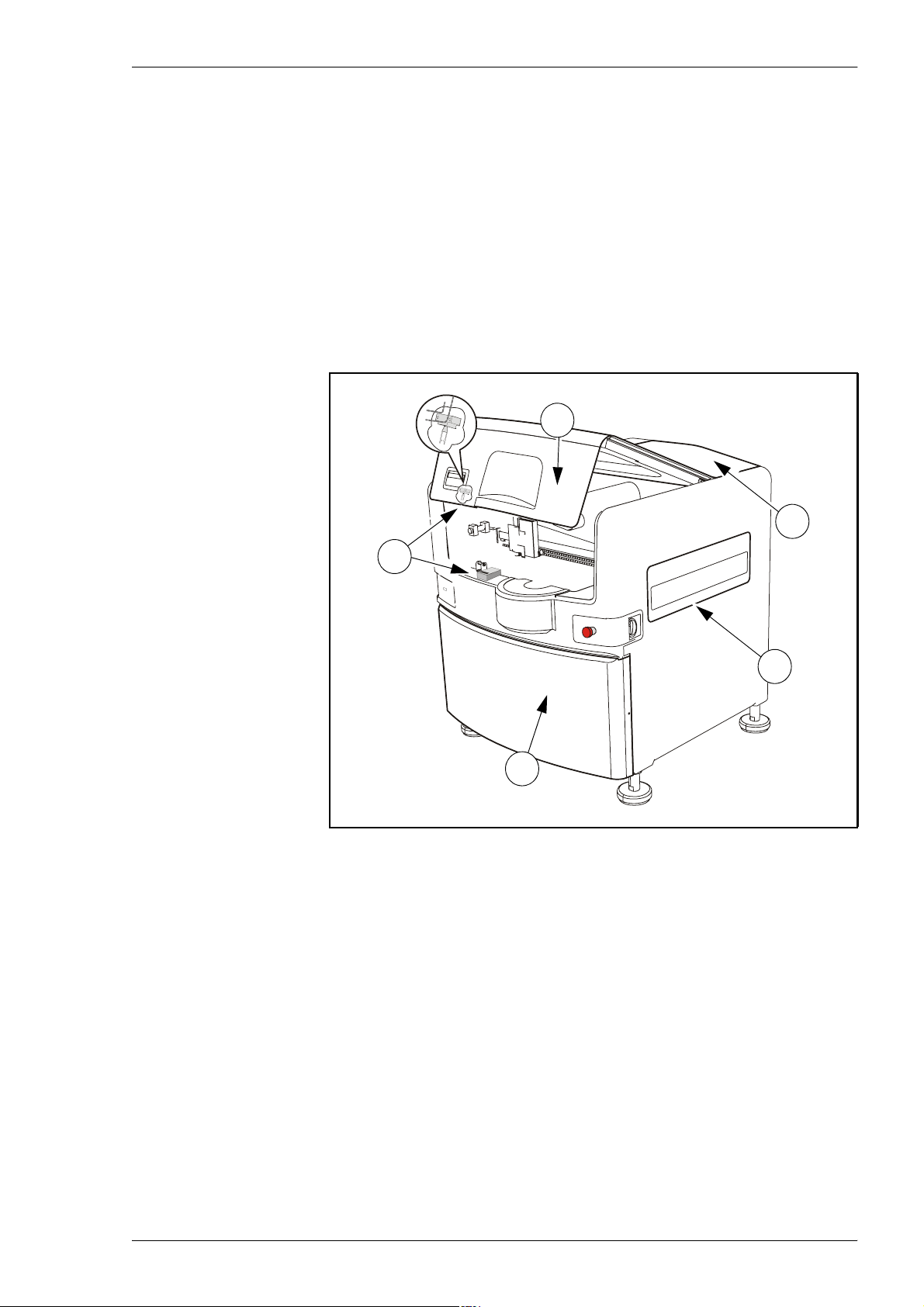
1
2
4
3
Figure 1-3. Safety hoods and switch on a MY500.
The following safety hoods and devices are found on the machine:
1. Hood front.
2. Hood front safety switch.
5
3. Front cover.
4. Side hood (one on each side of the machine).
5. Hood back.
P-030-0014-EN – Service Manual Rev. 0003 2008-06 1 - 3
Page 14
Safety MY500 JetPrinter MYDATA
Warning Signs
The warning signs on the machine must be observed as this machine contains
fast moving parts, magnetic fields, and high voltage. The machine has warning
signs placed as shown on the following pages.
At least one manual that describes the warning signs of the particular machine
type must always be kept, for instance if the machine is upgraded with a later
TPSys version.
Optional devices have the warning signs shown in their documents.
Number and position of each sign type is described in the following text. If a
sign is missing, it must be replaced immediately. Part numbers are printed on
the signs, and can also be read from this description.
All signs must be kept clean and readable.
Fast Moving Machinery
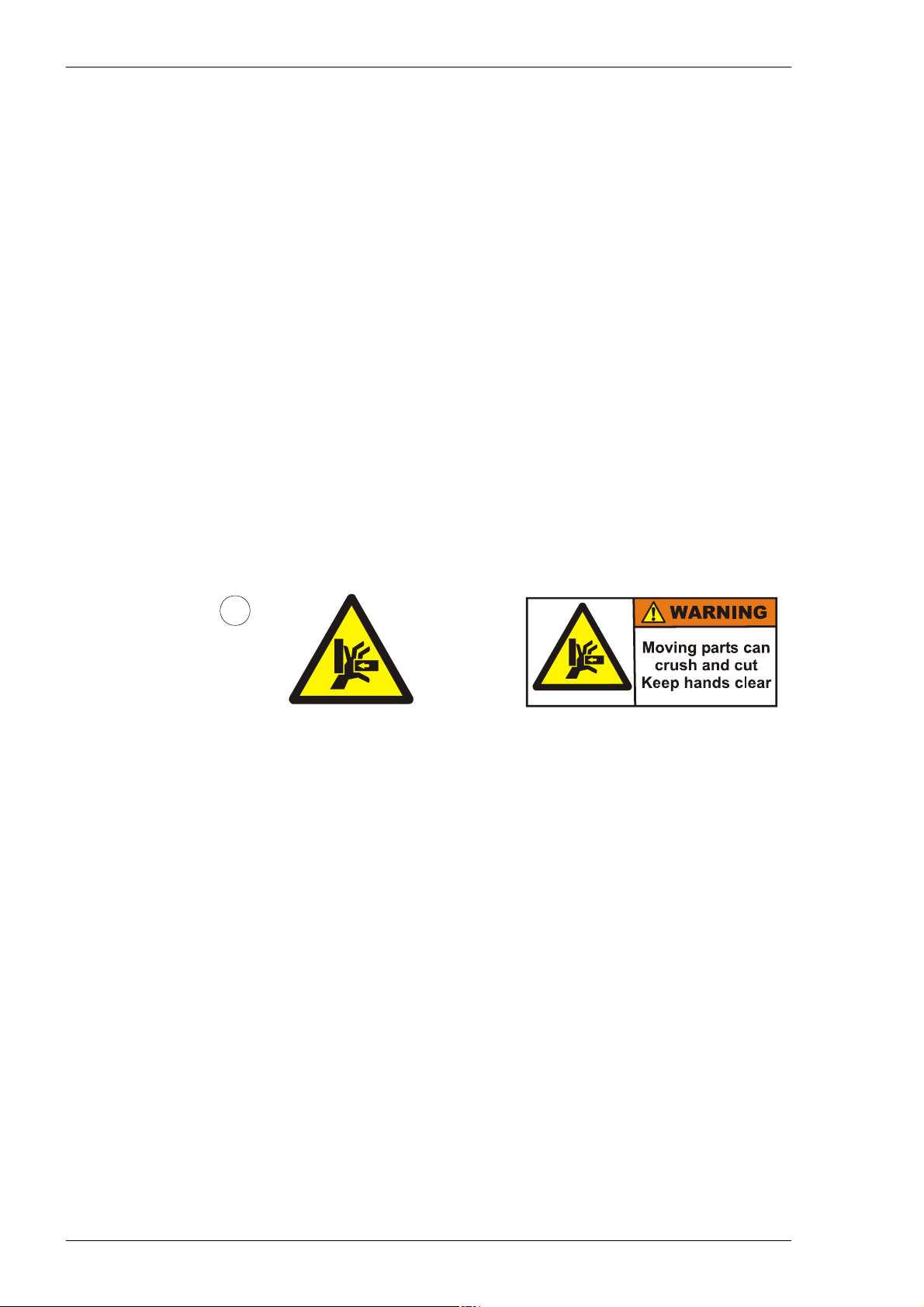
Sign 1 warns of the fast machine movement. No hands, fingers, or other
objects are allowed beyond the shield. Ensure that all covers and shields are
intact, mounted and closed while the machine is in operation. Do not disable
or disengage any safety switch or sensor.
1
European and
Canadian
standards
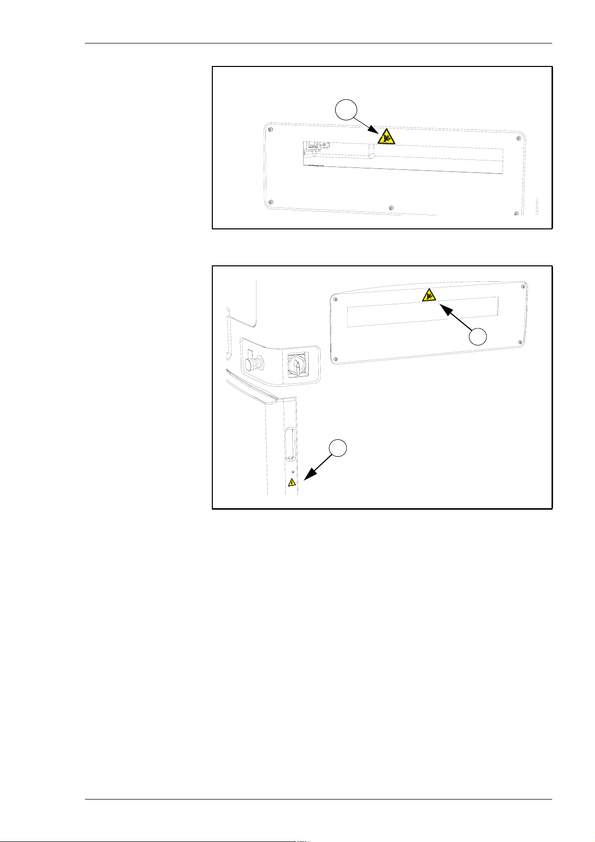
These signs are applied as follows:
– One sign on the left side protective shield, see Figure 1-4.
– One sign on the right side protective shield, see Figure 1-5.
US standards
1 - 4 Rev. 0003 2008-06 P-030-0014-EN – Service Manual
Page 15
MYDATA MY500 JetPrinter Safety
1
Figure 1-4. Warning sign on the machine’s left side hood.
1
2
Figure 1-5. Warning signs on the machine’s right side hood.
P-030-0014-EN – Service Manual Rev. 0003 2008-06 1 - 5
Page 16
Safety MY500 JetPrinter MYDATA
Dangerous Voltage
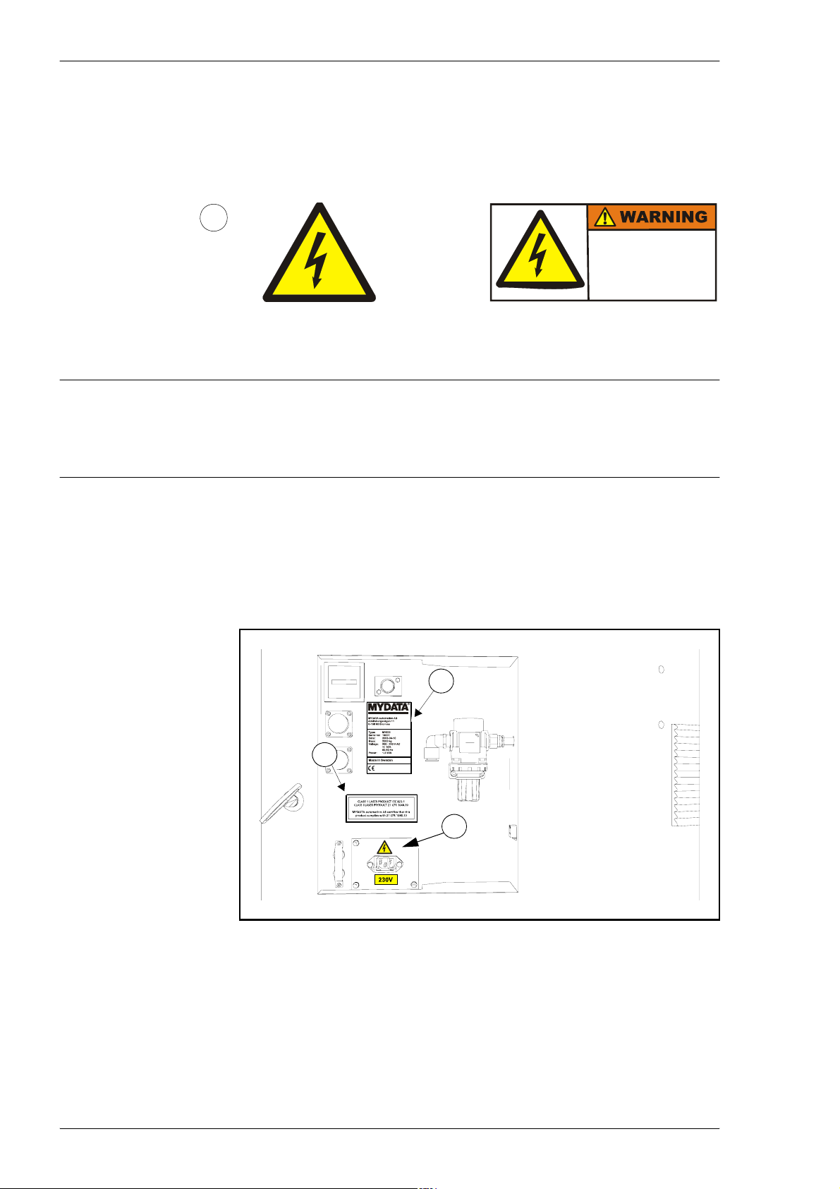
These signs warns of electric shock. Units on which this sign is placed contain
dangerous voltage levels. Power must be switched off before opening the unit.
Only authorized service personnel are allowed to operate the machine when
such a unit is open.
2
HAZARDOUS
VOLTAGE.
Disconnect power
before servicing.
European and
Canadian
standards
DANGER! Always lock out and tag the main switch before opening the hoods
and commencing any servicing within the machine. Always use the main
switch to restart the machine or any of its components.
This sign is applied as follows:
– One sign on the front cover, see Figure 1-5.
– One sign by the power supply unit on the connection plate at the rear
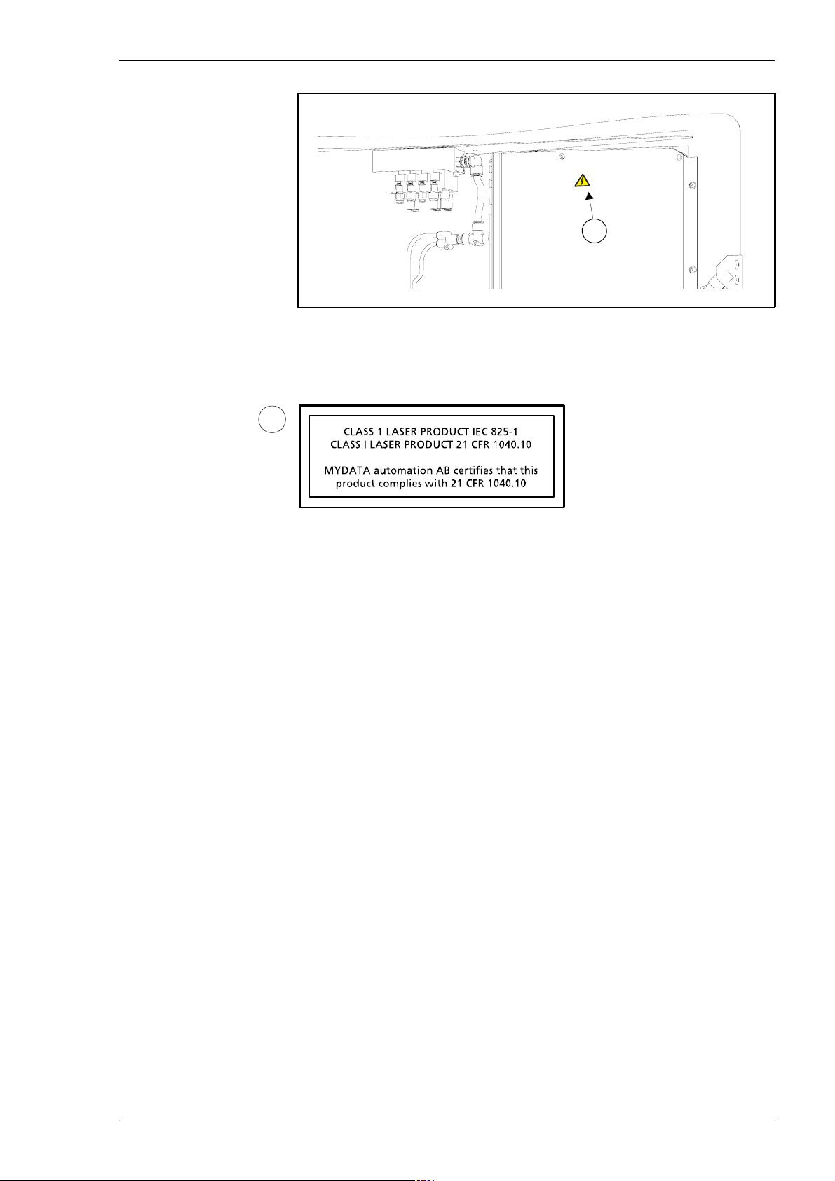
of the machine, see Figure 1-6.
– One sign on the inside of the connection plate, see Figure 1-7.
5
US standards
3
2
Figure 1-6. Warning signs at the rear of the machine.
1 - 6 Rev. 0003 2008-06 P-030-0014-EN – Service Manual
Page 17
MYDATA MY500 JetPrinter Safety
2
Figure 1-7. Warning sign at the connection plate inside.
Laser Classification
3
Sign 3 states the laser classification for the MY500 JetPrinter. One
certification sign is applied as shown in Figure 1-6.
P-030-0014-EN – Service Manual Rev. 0003 2008-06 1 - 7
Page 18
Safety MY500 JetPrinter MYDATA
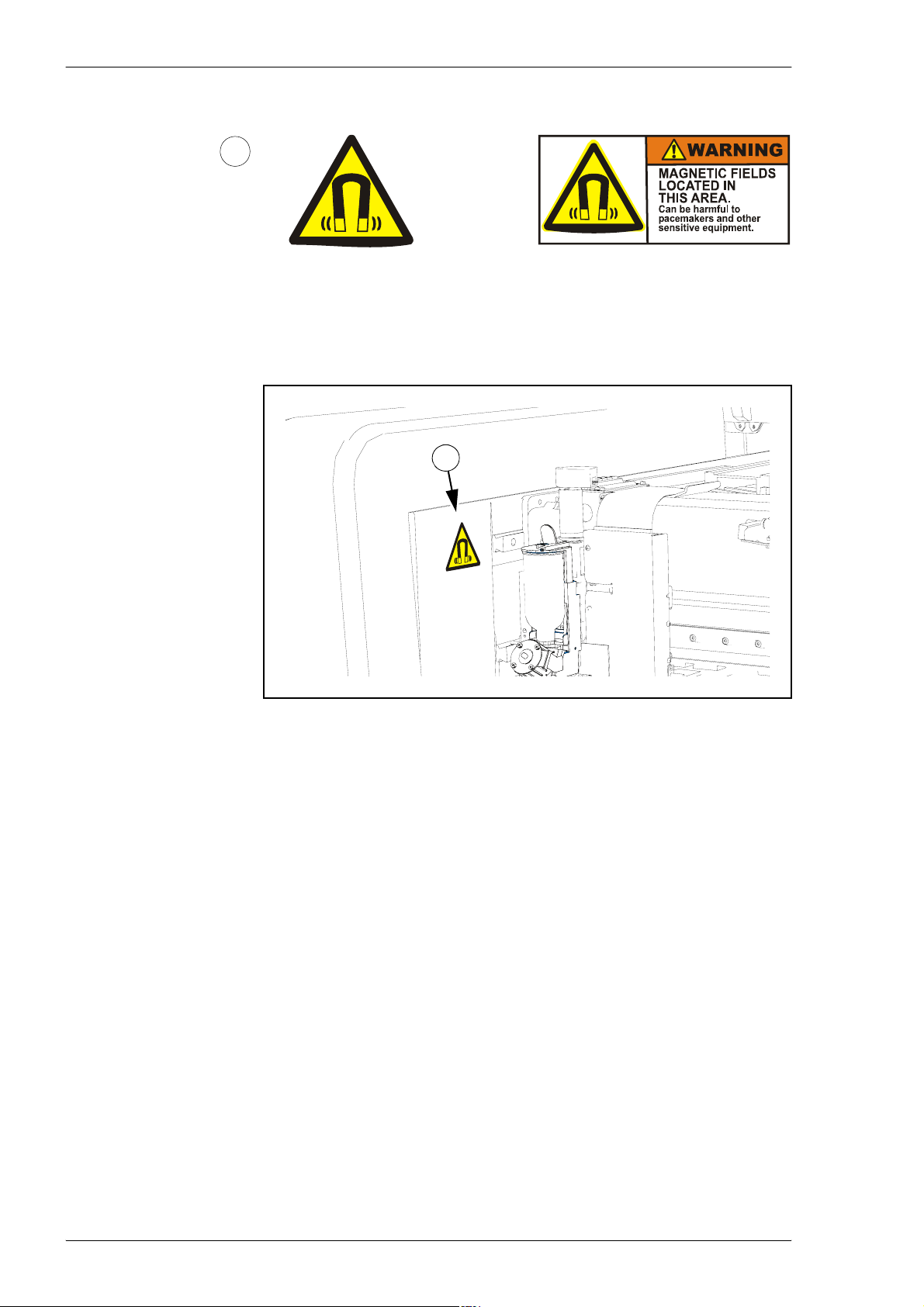
Magnetic Fields
4
European and
Canadian
standards
US standards
Sign 4 warns for magnetic fields. One warning sign is applied as shown in
Figure 1-8.
4
Figure 1-8. Warning signs inside the machine.
1 - 8 Rev. 0003 2008-06 P-030-0014-EN – Service Manual
Page 19
MYDATA MY500 JetPrinter Safety
Type Plate
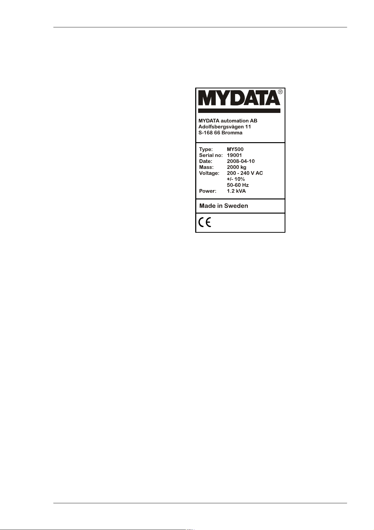
The type plate shows the name and address of the manufacturer, the machine
type and serial number, and manufacturing date and country. An exampl e of a
type plate is shown below.
Noise
Figure 1-9. Machine type plate.
The type plate is found at the back of the machine, see '5' in Figure 1-6.
For the MY500 JetPrinter, the equivalent continuous sound pressure level is
measured to be 68 dB(A).
P-030-0014-EN – Service Manual Rev. 0003 2008-06 1 - 9
Page 20
Safety MY500 JetPrinter MYDATA
Equipment Precautions
This section has to be read before handling the machine.
CAUTION! Always ensure that there are no foreign objects on the conveyor
Magnetic Fields
or within the X wagon and Y beam moving areas before operating the
machine.
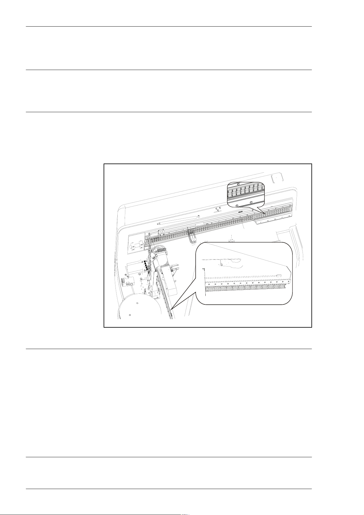
There are permanent magnets on the Y beam and in the stone frame. They
have extremely powerful magnetic fields.
Figure 1-10. Permanent magnets.
DANGER! Personnel wearing pace-makers must be careful in the vicinity of
1 - 10 Rev. 0003 2008-06 P-030-0014-EN – Service Manual
permanent magnets.
CAUTION! Do not approach permanent magnets when carrying objects made
of iron, steel or nickel. The force of attraction may cause fingers to be bruised.
CAUTION! Do not wear watches in the vicinity of permanent magnets since
they can be damaged.
CAUTION! Do not bring magnetic data media, check or credit cards near
permanent magnets. The data on the data media may be erased by the
magnetic field.
Page 21

MYDATA MY500 JetPrinter Safety
Compressed Air
This machine uses compressed air for its operation.
WARNING! Compressed air can be dangerous if handled incorrectly.
Assembly, handling, or repair of pneumatic systems must be performed by
trained and experienced personnel.
Solder Paste, Glue and Conditioner
Cassettes for the machine contain solder paste, which is a mixture of powder
and flux. They can also contain glue. Ejectors are filled with conditioner at
delivery.
WARNING! During handling and use, solder paste, glue and conditioner may
be hazardous to health and to the environment. Read the Material Safety Data
Sheet and warning label before usage.
Waste Disposal
Always remember that care should be taken to avoid the ingestion of
chemicals. They may contain lead and other toxic materials, so gloves, safety
goggles and gowns should be worn during handling, and hands should be
washed afterwards.
– Observe normal standards for handling chemicals.Avoid breathing
vapour. Avoid contact with skin and eyes. Wash hands before breaks
and after work. Wear personal protective equipment appropriate to the
task.
– Avoid breathing vapour. Avoid contact with skin and eyes. Wash
hands before breaks and after work. Wear personal protective
equipment appropriate to the task
Solder paste and any material with remnants of solder paste must be treated as
hazardous waste. This also applies to glue.
Do not allow to get into waste water or waterways. If this occurs, inform the
relevant water authority at once.
Empty containers may contain product residue.
Observe all label precautions.
P-030-0014-EN – Service Manual Rev. 0003 2008-06 1 - 11
Page 22

Safety MY500 JetPrinter MYDATA
Material Safety Data Sheets
The machine is shipped with various types of grease and oil. Below are
references to descriptions of chemical composition and toxicity (Material
Safety Data Sheets, shortened to MSDS) of these products.
If you have problems accessing the web sites referenced below, contact
MYDATA support.
Greases
GREASE PASTE OKS 270, part number K-013-0014
MSDS is found at http://www.mydata.com, document number P-0400137-EN. A logon user name and password may be required.
GREASE AFA+70 THK, part number K-035-0095
MSDS is found at http://www.mydata.com, document number P-0350095-EN. A logon user name and password may be required.
Solder Paste
Glue
Conditioner
SENJU SPARKLE PASTE OZ 2062-AC19 F13, part number L-038-0185
MSDS is found at http://www.mydata.com, document number P-0380010-EN. A logon user name and password may be required.
SENJU ECOSOLDER PASTE M705-LFAC19, part number L-038-0186
MSDS is found at http://www.mydata.com, document number P-0380012-EN. A logon user name and password may be required.
ALMIT SRC SN62U SS4M, part number L-038-0187
MSDS is found at http://www.mydata.com, document number P-0380014-EN. A logon user name and password may be required.
ALMIT LFM-48U MDA-5, part number L-038-0188
MSDS is found at http://www.mydata.com, document number P-0380016-EN. A logon user name and password may be required.
HERAEUS PD 205 A-JET
Request MSDS from your local distributor, or the manufacturer
W.C. Heraeus GmbH (http://www.4cmd.com).
INDIUM C-1
Request MSDS from your local distributor, or the manufacturer Indium
Corporation of America (http://www.indium.com).
1 - 12 Rev. 0003 2008-06 P-030-0014-EN – Service Manual
Page 23

MYDATA MY500 JetPrinter Safety
In Case of Fire
Only use carbon dioxide (CO2) extinguishers or dry chemical extinguishers in
case of fire. Under no circumstances use water, as the machine contains
electronic equipment.
ESD
ESD, ElectroStatic Discharge, is one of the few things an individual can
unwittingly do to damage or destroy components. Much like the shock you
receive when rubbing your feet on a carpet and then touching some metal. ESD
can occur when working and will cause components you touch to no longer
work properly.
How To Help Prevent ESD
The following steps help reducing the chances of ESD:
– Do not touch components unless you are constantly earthed by an
– Always ensure that people, the workplace and packaging are safely
– If the packaging is not conductive, place the modules in a conductive
– Make sure not to wear any clothing that conducts a lot of electrical
– Most plastics can easily become charged and must therefore be kept
– Do not touch electronic modules unless it is absolutely necessary to
All MYDATA machines have jacks for wrist straps. They are marked with an
ESD sign.
ESD wrist strap or you are wearing ESD shoes or ESD shoe earthing
strips on an ESD floor.
earthed when handling electrostatic sensitive components.
envelope before packaging. Use ESD bags, domestic aluminum foil
or paper, for example. Never use plastic bags or film.
charge, such as a wool sweater or synthetic fibers.
away from components.
do so in order to carry out other work. If it is necessary, make sure that
you do not touch pins or printed conductors .
P-030-0014-EN – Service Manual Rev. 0003 2008-06 1 - 13
Page 24

Safety MY500 JetPrinter MYDATA
1 - 14 Rev. 0003 2008-06 P-030-0014-EN – Service Manual
Page 25

MYDATA MY500 JetPrinter Installation
2. Installation
In this chapter you will find the following information:
– Site Preparation on page 2-2.
Describes what is required of the site for a successful installation.
– Installation on page 2-7.
Describes how to install the machine at the site. There is also site
preparation check list on page 2-22.
P-030-0014-EN – Service Manual Rev. 0003 2008-06 2 - 1
Page 26

Installation MY500 JetPrinter MYDATA
Site Preparation
In this section you will find prerequisites of what is required of the site for a
successful installation of a MYDATA MY500 JetPrinter. Details about the
working area, environmental and electrical requirements, and regulatory
compliance are given. Follow these directions to ensure a safe and proper
installation, as well as ongoing operating efficiency.
Site preparation check list
1. Identify the desired location for the machine. Verify that enough space
is available.
2. Verify that all environmental requirements are met, for example:
– Temperature
– Humidity
– Cleanliness/airborne contaminants.
3. Verify that the floor is level and can take the weight.
4. Plan the transportation route to the installation site.
5. Verify that means for transportation and lifting are available (for
6. Obtain required, stable input power.
7. Obtain pneumatic air connection.
8. Arrange for electrostatic avoidance equipment.
9. Table (and chair) for offline station.
10. Network connection.
Required Working Area
Space around the machine is necessary for maintenance of the machine and
optional equipment, if any. Prepare a suitable working area according to the
dimensions shown in Figure 2-1, Figure 2-3 and Figure 2-4. The dimensions
shown are the minimum space required for the machine with no extra options
or external conveyors. To achieve a more efficient working area, add space for
operating personnel and storage area for solder paste and boards.
Check that the transportation route can take the weight of the machine.
instance fork lift or crane).
Machine weight
The floor, on which the machine is transported and finally positioned, must
support the machine weight, which is 2 000 kg net weight.
2 - 2 Rev. 0003 2008-06 P-030-0014-EN – Service Manual
Page 27
MYDATA MY500 JetPrinter Installation
Shipping gross weight
The shipping gross weight depends on the quantity of delivered options. An
usual gross weight is the machine weight plus roughly 100 kg.
The site
The floor at the machine site must be level.
It is recommended that the area at the machine site is ESD (Electrostatic
Discharge) protected.
Cable for mains, tube for pneumatic air, and cable for computer network are
connected to the machine at the rear (shown in Figure 2-3). The machine is
delivered with two network cables. One cable, 1 m of length, for the
connection of the offline station to a gateway. One cable, 30 m of length, for
the connection of the MY500 JetPrinter.
CAUTION! Always make sure that the way cables and tubes are placed do not
present a hazard. Always use cable ties or such to bundle them together, or
place in cable channels.
The machine noise is maximum 68 dB (A).
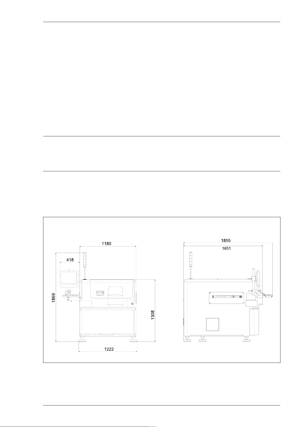
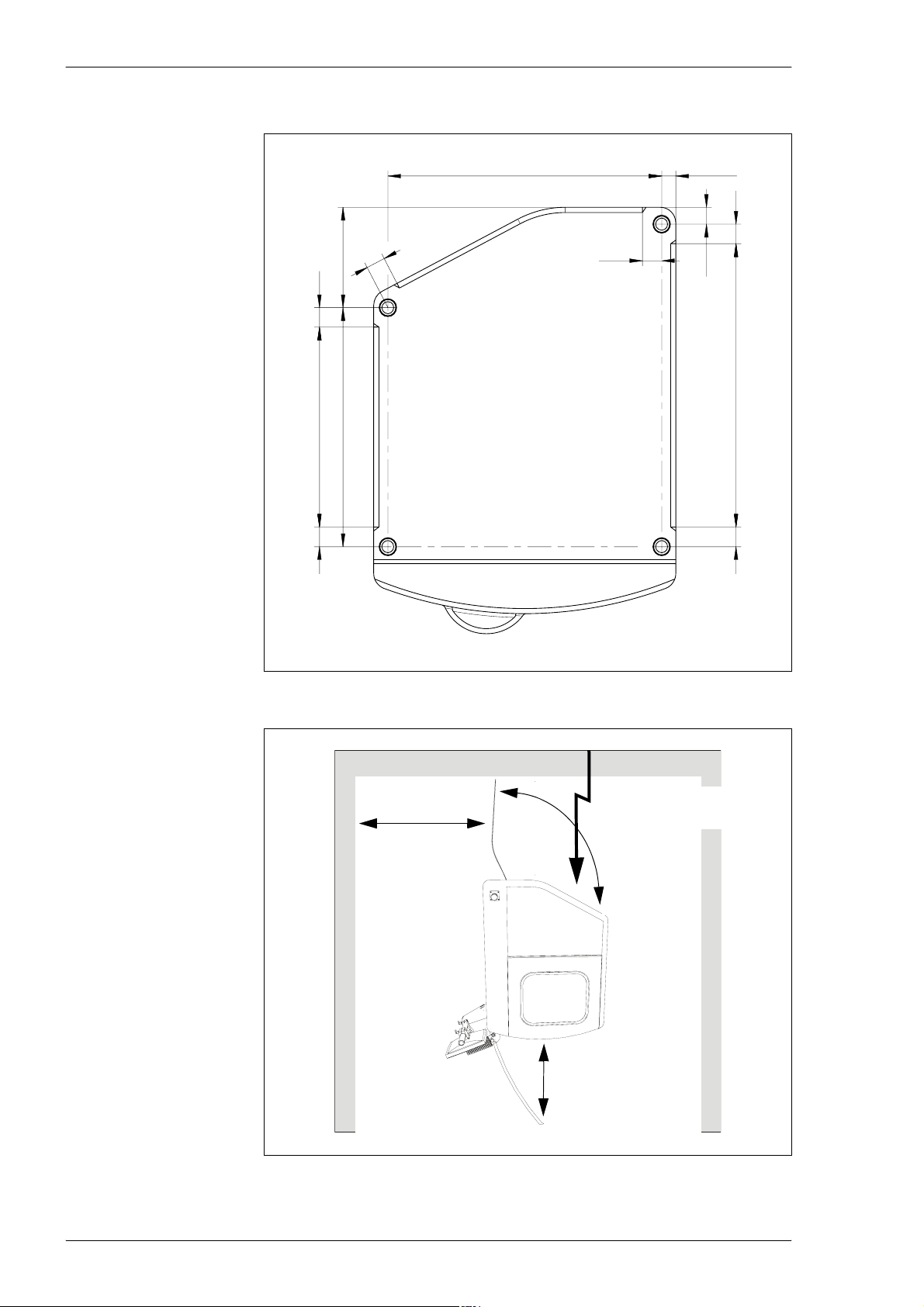
Machine dimensions
All dimensions shown in Figure 2-1 are in mm.
Figure 2-1. Main dimensions.
P-030-0014-EN – Service Manual Rev. 0003 2008-06 2 - 3
Page 28
Installation MY500 JetPrinter MYDATA
1070
75
386
75
769
919
75 75
Bottom view
75
55
75
65
1090
Figure 2-2. Machine footprint.
1 000 mm
1 000 mm
1000mm
Power, network and
compressed air in.
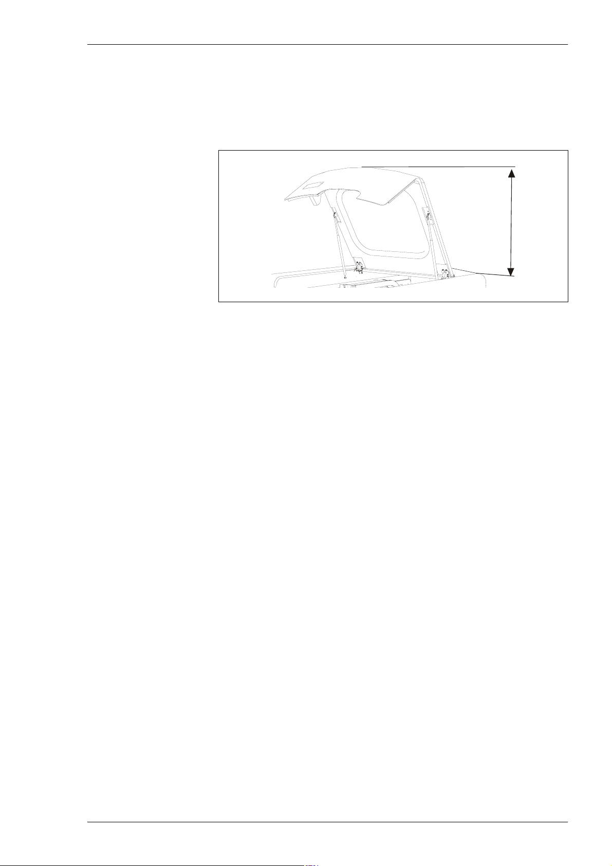
Figure 2-3. Clear space required around the machine.
2 - 4 Rev. 0003 2008-06 P-030-0014-EN – Service Manual
Page 29
MYDATA MY500 JetPrinter Installation
Figure 2-3 shows a top view over the required service area around the machine
(measurements in mm). Also the position of the network and power inlets are
shown in the figure. Note that there is no specific area required on the sides of
the machine. It is sufficient to be able to pass around to the backside.
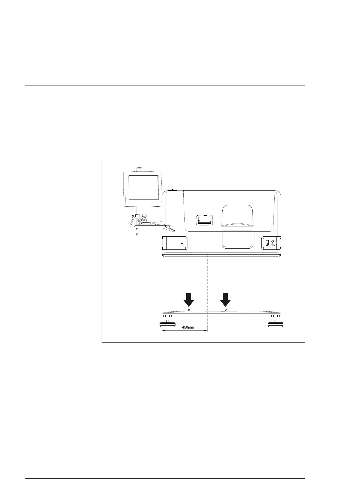
Figure 2-4 shows the space required above the machine.
750 mm
Figure 2-4. Clear space above the machine.
If you have the optional Air Cooling unit, this will require a minimum distance
of 400 mm to the nearest wall or machine.
Environmental Requirements
Temperature
Operating: +18 to +30 °C with full performance.
Storage: –30 to +65 °C
Relative humidity
Operating: <95 %, non-condensing
Storage: 100 %
Altitude
The MY500 JetPrinter is capable to operate correctly at altitudes up to 1 000 m
above mean sea level.
+5 to +18 °C and +30 to +40 °C with no guarantee of the
accuracy.
Dust and dirt
The machine does not require a clean-room environment but dust and dirt must
be kept as low as possible. The maintenance intervals are shortened by high
temperature and dusty or dirty environment.
P-030-0014-EN – Service Manual Rev. 0003 2008-06 2 - 5
Page 30

Installation MY500 JetPrinter MYDATA
Electrical Requirements
Always follow the existing local, national or international regulations when
installing this equipment.
Acceptable voltages (±10 %): 230/115 VAC.
Compressed Air
The pneumatic system in the machine requires compressed air. Minimum
pressure required is 7 bar, maximum allowed is 10 bar.
Transporting the Machine
Whenever the machine has to be transported, avoid vibrations and impacts in
order to prevent damage to the machine. It must be ensured that the machine
is stable while it is being transported.
Truck transport
Remove the optional equipment and the MMI-module (i.e. the arm and tube
holding the screen and keyboard) and by-pack it in a separate box.
Secure the Y beam with the transport lock, see page 2-20 for details on the
lock. Fix the X wagon in position secured to the cassette exchange plate using
cable ties, see Figure 2-17. To secure the X wagon do as follows:
– Position the X wagon above the cassette exchange plate.
– Draw the cable ties through the holes in the plate.
– Tighten them around the end stops of the x-wagon. The cable ties
must be tight enough to ensure that the X wagon does not move.
CAUTION! Ensure that the left cable tie does not touch the camera.
To prevent dust and dirt to enter the machine you should wrap it in plastic.
Please refer to page 2-10 for details on how to lift and move the machine.
Use strong straps to secure the machine and equipment to the truck bed. The
machine should be tied down to the truck bed with straps attached to the
machine’s leveling feet.
Air and sea transport
For air and sea transport there is a special crate, and special locking brackets
available from MYDATA.
2 - 6 Rev. 0003 2008-06 P-030-0014-EN – Service Manual
Page 31

MYDATA MY500 JetPrinter Installation
Installation
Upon arrival the machine must be unpacked, lifted, moved to the machine site
and leveled.
This section describes how to perform the installation tasks and is divided into
the following main parts:
– Unpacking on page 2-9.
– Lifting the Machine on page 2-10.
– Moving and Placing the Machine on page 2-12.
– Powering on page 2-14.
– Network Connection on page 2-19.
– Software Installation on page 2-22.
Equipment
Standard tools.
•
• Set of Allen Keys (mm).
• Spirit level and 70mm wrench.
• Lifting equipment.
• Calibration tools:
– L-030-0119 Conveyor calibration card.
– D-007-0728 Calibration ruler.
– L-038-0193 Height reference tool.
P-030-0014-EN – Service Manual Rev. 0003 2008-06 2 - 7
Page 32

Installation MY500 JetPrinter MYDATA
Installation Summary
This is a summary of the installation process of a MY500 JetPrinter:
– Unpack the machine and all other packages.
– Check the ’Shock Watch’ and ’Tilt Watch’ gages.
– Check that all ordered parts are delivered.
– Place the machine at the desired position.
– Make sure that the machine is level, and that all machine’s feet make
contact with the floor.
– Attach the desired plug to the 1 phase cable.
Before connecting the input power verify that it is the same as the
label on the back door.
– Connect air through cooling unit or optional filter unit.
Ensure that pressure is 7 bar.
– Switch on the machine power.
– Check the voltage with the Service program.
– Use Service program to check all safety switches (hoods & emergency
buttons).
–Run HardwareInstall.
– Check the surrounding equipment that follows with the machine, i.e.
Light tower.
– Install the barcode scanner.
– Make a backup.
2 - 8 Rev. 0003 2008-06 P-030-0014-EN – Service Manual
Page 33

MYDATA MY500 JetPrinter Installation
Unpacking
The machine is shipped in a wooden crate (outside Europe) and must be
handled with care. It is strongly recommended that a MYDATA representative
is present when the machine is unpacked.
1. Inspect the ’Shock Watch’ and ’Tilt Watch’ gages for activation and the
crate for damages. These must be annotated on the Bill of Lading and
goods received note.
2. Remove the top lid.
3. Remove the rear and front sides of the box.
4. Remove the plastic protection.
5. Remove additional packages fastened to the machine (for instance
monitor, keyboard, and offline PC).
6. Release the machine from the bottom of the box.
7. Inventory all packages to ensure that the correct items are delivered
according to the packing list. If not, contact your local MYDATA
representative.
Items that are always included:
– Power cable.
– Monitor, keyboard and trackball.
– Offline PC (with cables).
– Spare part kit.
– Calibration tools
L-030-0119 Conveyor calibration card.
D-007-0728 Calibration ruler.
L-038-0193 Height reference tool.
– Operator’s manual.
– Prog ramming manual.
– Service manual.
P-030-0014-EN – Service Manual Rev. 0003 2008-06 2 - 9
Page 34
Installation MY500 JetPrinter MYDATA
Lifting the Machine
To avoid tilting or damaging the machine, always lift the machine as described
below. The description includes fork lift as well as crane lift.
The machine weighs 2 000 kg net.
WARNING! Lift the machine as described below. Otherwise, the machine may
become damaged and the lifting may become dangerous.
Fork lift
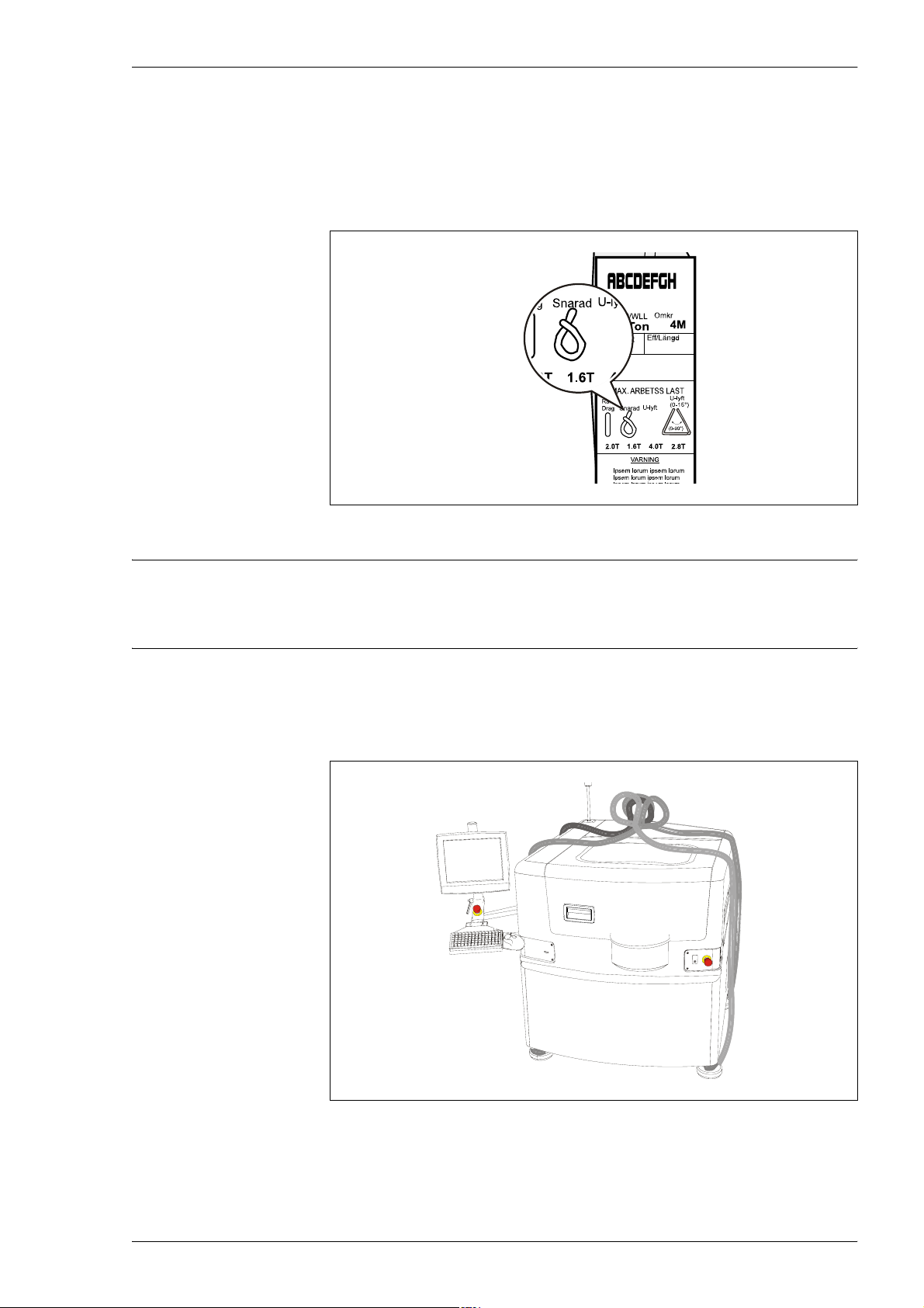
Always lift the machine as shown in Figure 2-5.
Figure 2-5. Fork lift.
Arrows on the machine's cover indicate the correct points where to insert the
fork lift. If the fork lift is inserted anywhere else there is a risk that the machine
can tip over. The center of gravity is located slightly to the left and towards the
front on the machine.
2 - 10 Rev. 0003 2008-06 P-030-0014-EN – Service Manual
Page 35
MYDATA MY500 JetPrinter Installation
Crane lift
We recommend using four flat webbing slings to lift the MY500 JetPrinter
with a crane. They are slung around the leveling feet of the machine.
The slings must be able to carry 1.6 tons each when snared. This is indicated
on the label on the sling, see Figure 2-6.
Figure 2-6. Webbin g sling label.
The machine's center of gravity is located near the front. Therefore, the
hoisting cable should be slightly shorter at the front.
Put the slings around the leveling feet. There are no special lifting devices on
the feet such as hoisting lugs. Place a piece of cardboard, or a blanket, between
the machine's frame and the hoisting cables. This will protect it when the
hoisting cable is stretched.
Figure 2-7. Flat webbing slings.
P-030-0014-EN – Service Manual Rev. 0003 2008-06 2 - 11
Page 36

Installation MY500 JetPrinter MYDATA
Moving and Placing the Machine
Move the machine to the final position and put it on the leveling feet. You can
use either a fork lift or a crane.
CAUTION! Always ensure that the transport lock is attached before moving
the machine. If not the Y wagon may be damaged, see page 2-20.
Leveling
When the machine has been placed in the final location, check the leveling as
described below.
1. Place a spirit level on the machine and adjust the leveling feet until the
machine is level in both directions.
2. Make sure that each leveling foot is screwed firmly against the floor so
that the weight of the machine is divided equally on the four feet.
3. Check if the machine is steady by manually trying to rock the machine.
If not, adjust the leveling feet.
4. Tighten the locking nut on each leveling foot.
2 - 12 Rev. 0003 2008-06 P-030-0014-EN – Service Manual
Page 37
MYDATA MY500 JetPrinter Installation
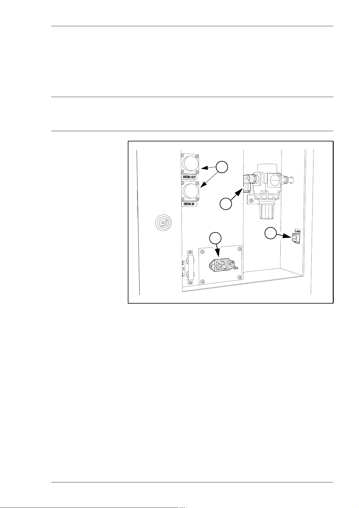
Main Machine Connections
The main connection points are found on the back of the machine. These
points are placed on the outside of the connection plate (the lower door).
This door can only be unlocked by a special key, which is provided with the
machine.
WARNING! There is dangerous voltage in units behind the door. Ensure that
the key is only available to trained maintenance personnel.
4
2
1
Figure 2-8. Main connections on machine backside.
The main connection points are:
1. Powering
This is where the mains power supply is connected, see page 2-14 for
details.
2. Pneumatic connection
This is where the compressed air is connected, see page 2-16 for details.
3
3. Network connection
The Local Area Network is connected here, see page 2-19 for details.
4. SMEMA Connectors
These connectors are used for the communication with external
conveyors, see page 2-19 for details.
P-030-0014-EN – Service Manual Rev. 0003 2008-06 2 - 13
Page 38
Installation MY500 JetPrinter MYDATA
Powering
MYDATA machines are set up for adequate mains supply before delivery
according to the customer order. This means, that normally only the mains
power needs to be connected without alterations inside the machine.
Knowing your mains power supply, you can verify that the machine is
properly set up by reading on the type label.
If the mains voltage or the type of mains supply is to be changed, internal
power connections in the machine must also be changed accordingly, see the
next section.
DANGER! The power configuration plugs should only be installed by an
Electrical Configuration
authorized MYDATA service engineer.
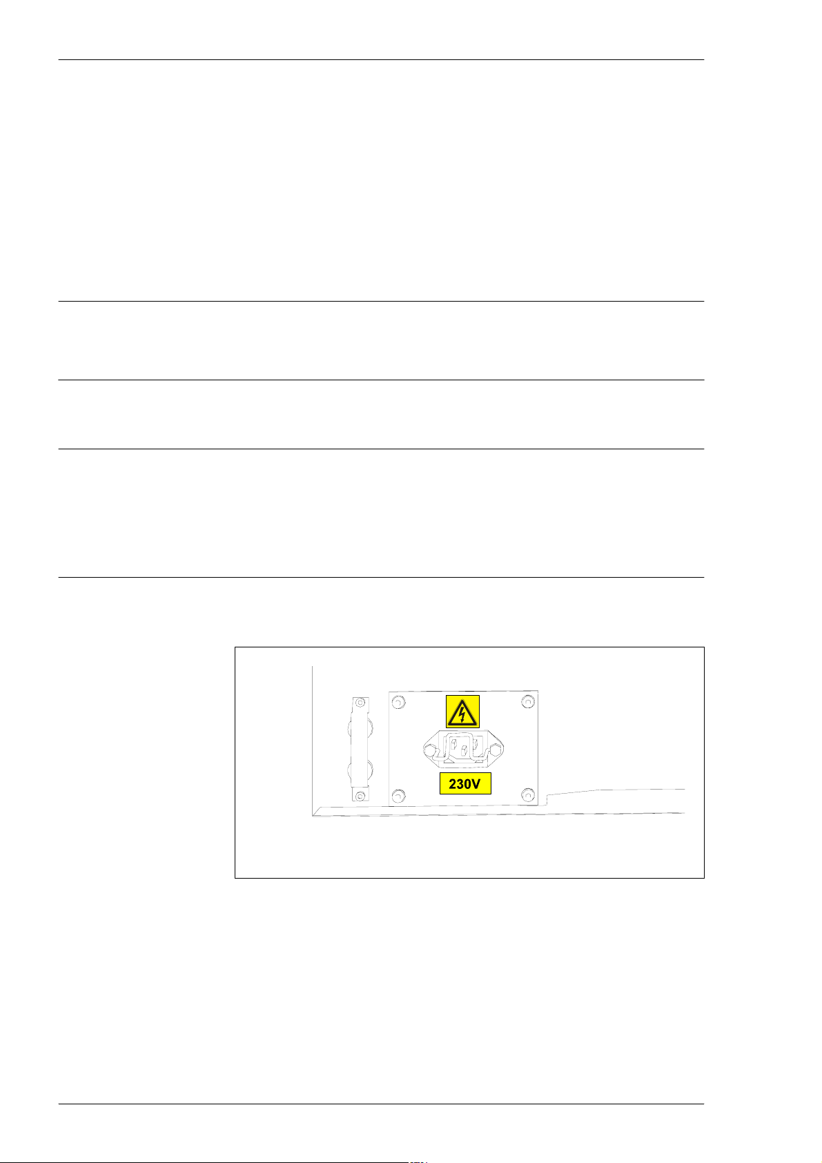
WARNING! Lock and tag, and disconnect the mains, before opening, or doing
any work inside the machine.
Always ensure that the voltage labeled on the machine (close to the mains
power inlet) corresponds to the mains. If not, check and when necessary
replace the configuration plugs.
The machine is equipped with one mains transformer which must be
configured according to the supply voltage.
Figure 2-9. Main power.
2 - 14 Rev. 0003 2008-06 P-030-0014-EN – Service Manual
Page 39
MYDATA MY500 JetPrinter Installation
Electrical Connection
This machine is intended to be stationary and movable to accommodate the
changing production needs of the end use factory (this is in compliance with
the NEC Article 400-7 and -8).
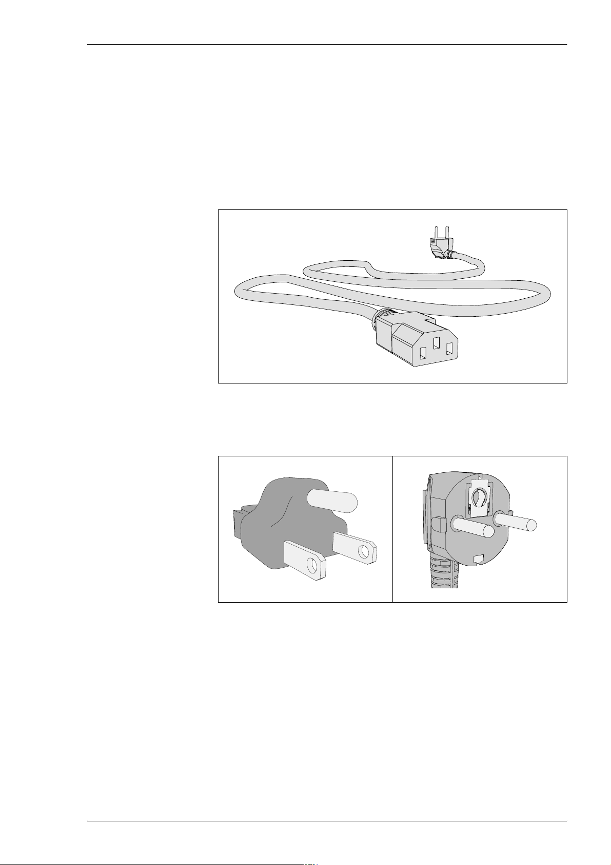
Power Plug Connection
The machine mains transformer is connected by the mains power cord shown
in Figure 2-10.
Figure 2-10. Power plug.
Connect the cable to the mains power. Available plug types are shown in
Figure 2-11 and 2-12.
Figure 2-11. Power plug, US. Figure 2-12. Power plug, Europe.
P-030-0014-EN – Service Manual Rev. 0003 2008-06 2 - 15
Page 40
Installation MY500 JetPrinter MYDATA
Pneumatic Connection
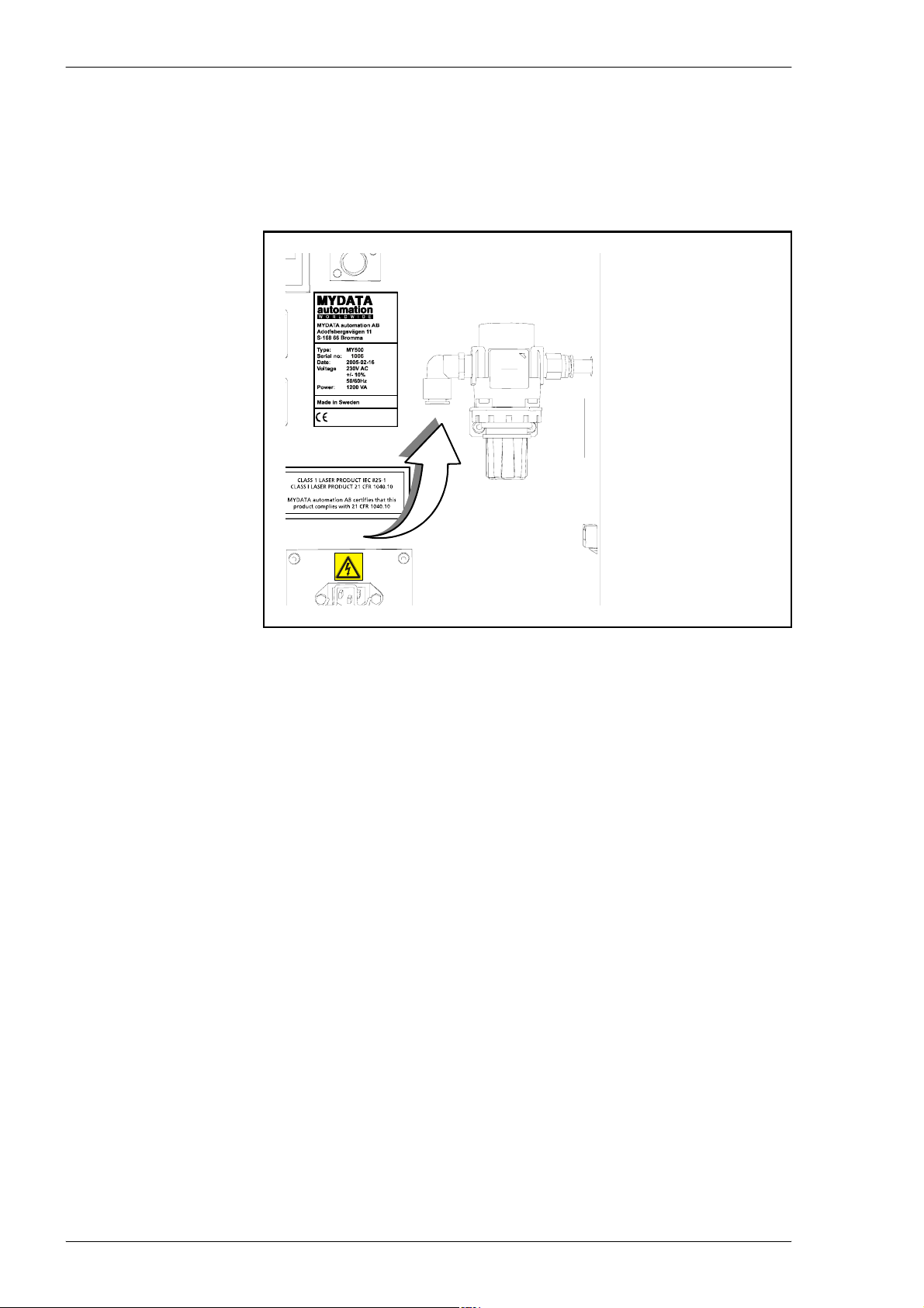
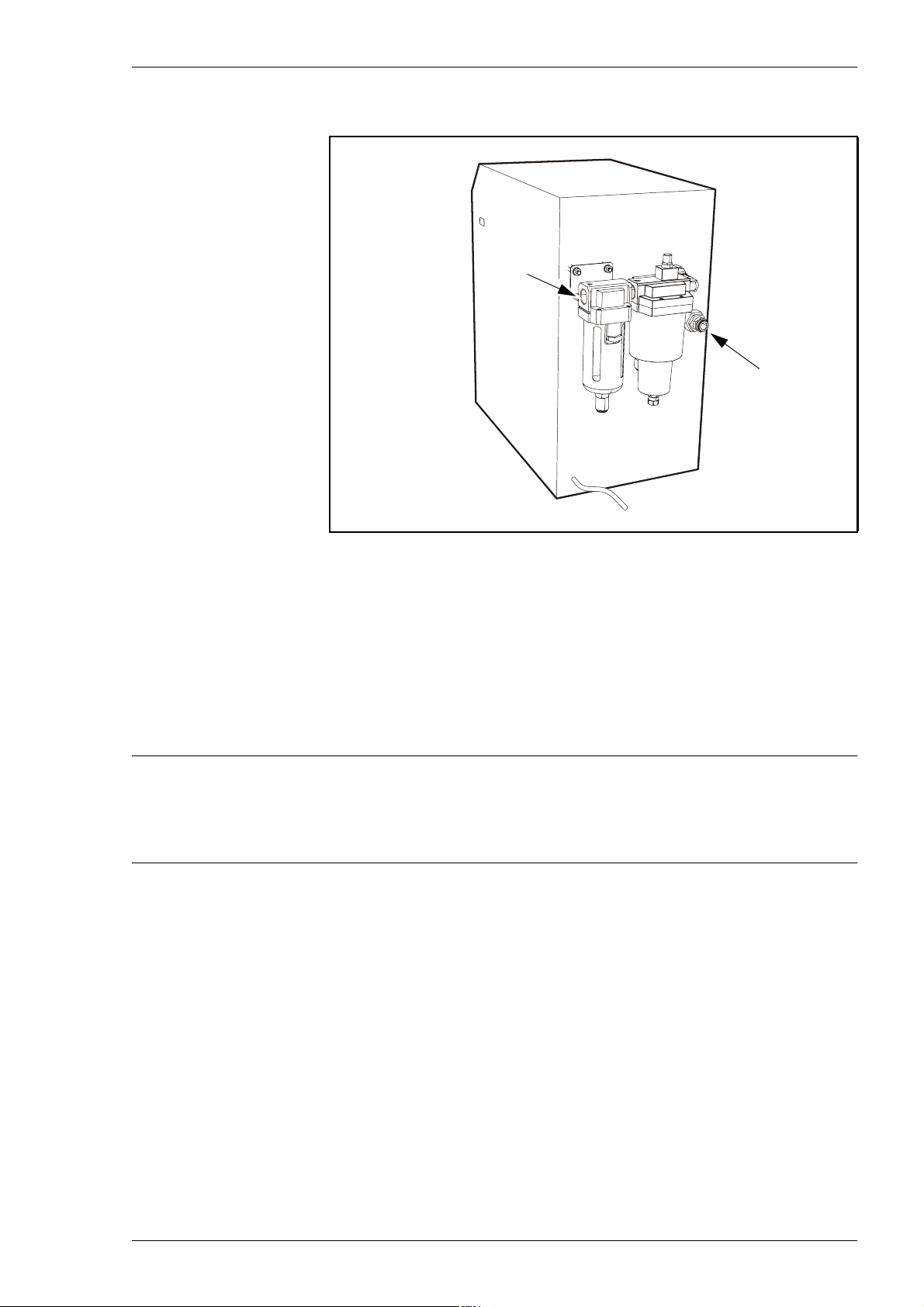
The pneumatic system in the machine require compressed air. Ensure that the
pressure is at least 7 bar.
The pressure hose is connected to the regulator on the backside of the machine.
Figure 2-13. Pneumatic valve on the MY500 JetPrinter.
There are two optional pneumatic air units available for installation – the air
cooling unit and the micro mist unit.
If any of these optional units are used, the compressed air will first be
connected to these. Thereafter the air will be connected to the pneumatic valve
on the MY500 JetPrinter.
2 - 16 Rev. 0003 2008-06 P-030-0014-EN – Service Manual
Page 41
MYDATA MY500 JetPrinter Installation
Optional Air Cooling Unit
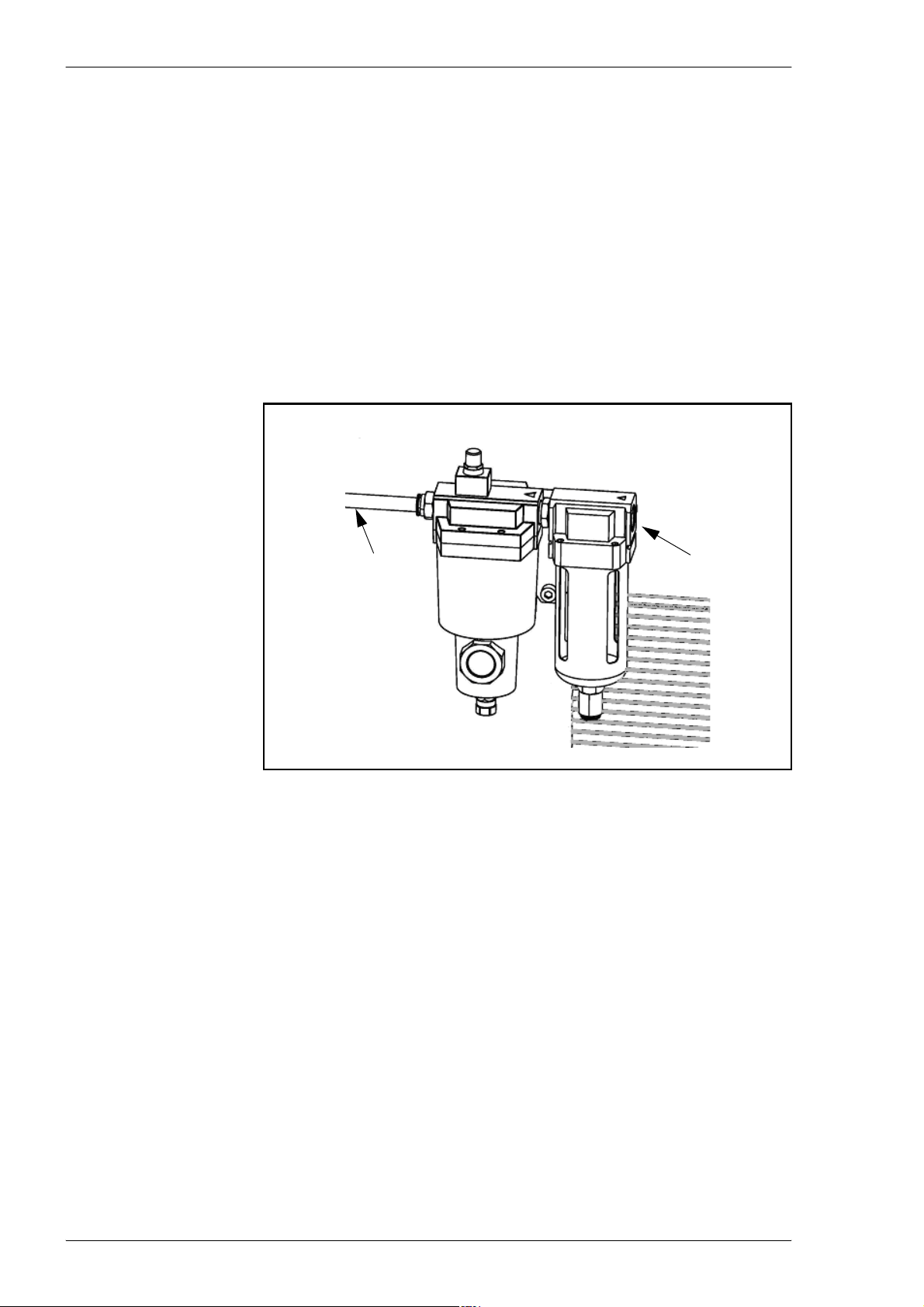
Air in
Air out
Figure 2-14. Air connections on cooling unit.
Air connections
Connect ’Air in’ of the Cooling Unit to compressed air 0.8–1.0Mpa.
Maximum compressed air in temperature is +55 °C. The connection has a
G ½ thread.
Connect an isolated tube to ’Air out’ of Air Dryer and to the pneumatic valve
on the MY500 JetPrinter.
CAUTION! Do not use any other tube than L-030-0045, to connect the
Cooling Unit with the MY500 JetPrinter. This because the MY500 JetPrinter
need both dried and cooled compressed air.
Electric connection
Connect the electrical cable to an grounded outlet with a voltage of:
– – 230 V 50 Hz AC for Cooling Unit L-030-0126.
– – 115 V 60 Hz AC for Cooling Unit L-030-0127.
P-030-0014-EN – Service Manual Rev. 0003 2008-06 2 - 17
Page 42
Installation MY500 JetPrinter MYDATA
Drain tube
Connect the blue drain tube to handle the condensation water properly.
The drain tube comes out from the bottom side of the air dryer.
Placement of Cooling Unit
Place the Cooling Unit in an open dust free space with max ambient
temperature of +40 °C.
The Cooling Unit must have a minimum distance of 0.4 m to nearest wall or
machine.
Optional Micro Mist Separator Unit
To MY500 JetPrinter
Air in
Figure 2-15. Micro mist separator unit.
Connect ’Air in’ of the Micro Mist Separator Unit to compressed air 0.8–
1.0Mpa.
Maximum compressed air in temperature is +35 °C. Thread of the ’Air in’
connection is G ½.
2 - 18 Rev. 0003 2008-06 P-030-0014-EN – Service Manual
Page 43
MYDATA MY500 JetPrinter Installation
Network Connection
MY500 JetPrinter movements are guided by a machine control software,
acting on instructions in the form of a machine programs (layouts). These
layouts are prepared on an offline terminal, a PC, which is connected to the
machine via a Local Area Network (LAN).
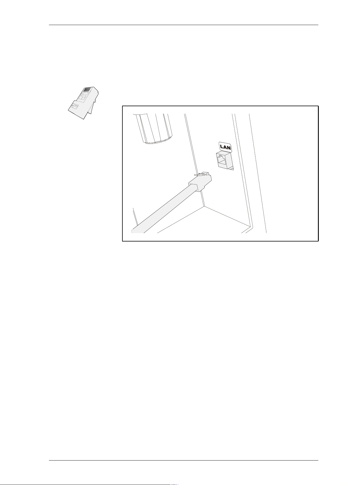
The network is connected onto the machine’s backside. The network cable use
RJ45 connectors.
Connect the offline PC to the machine via the gateway using the network
cables.
SMEMA Connection
Surface Mount Equipment Manufacturers Association (SMEMA), have
standardized the mechanical and the electrical interface in the SMEMA
Interface standard 1.2. Communications between surrounding surface mount
equipment, and a MY500 JetPrinter is handled by SMEMA-standardized
connectors.
The MY500 JetPrinter connection plate have are two SMEMA connectors –
SMEMA OUT and SMEMA IN. An external equipment’s SMEMA IN is
connected to the MY500 JetPrinter SMEMA OUT. SMEMA IN on the
MY500 JetPrinter is connected to the SMEMA OUT on the external
equipment.
Figure 2-16. LAN connection.
P-030-0014-EN – Service Manual Rev. 0003 2008-06 2 - 19
Page 44
Installation MY500 JetPrinter MYDATA
Transport Lock
CAUTION! Always remove the transport lock before powering up the machine
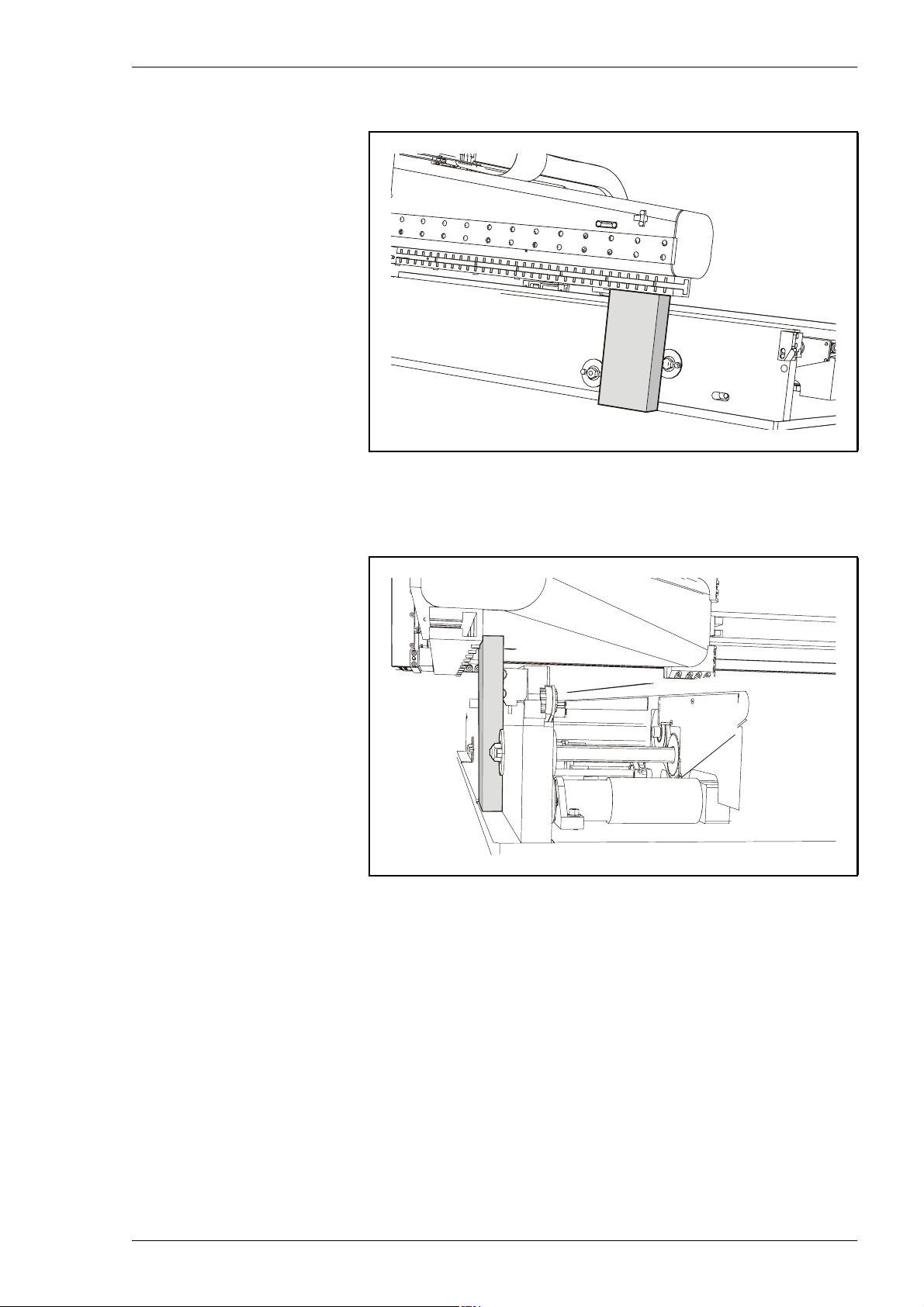
for the first time!
The Y beam and X wagon are locked in position during transport. These locks
must be removed before starting the machine.
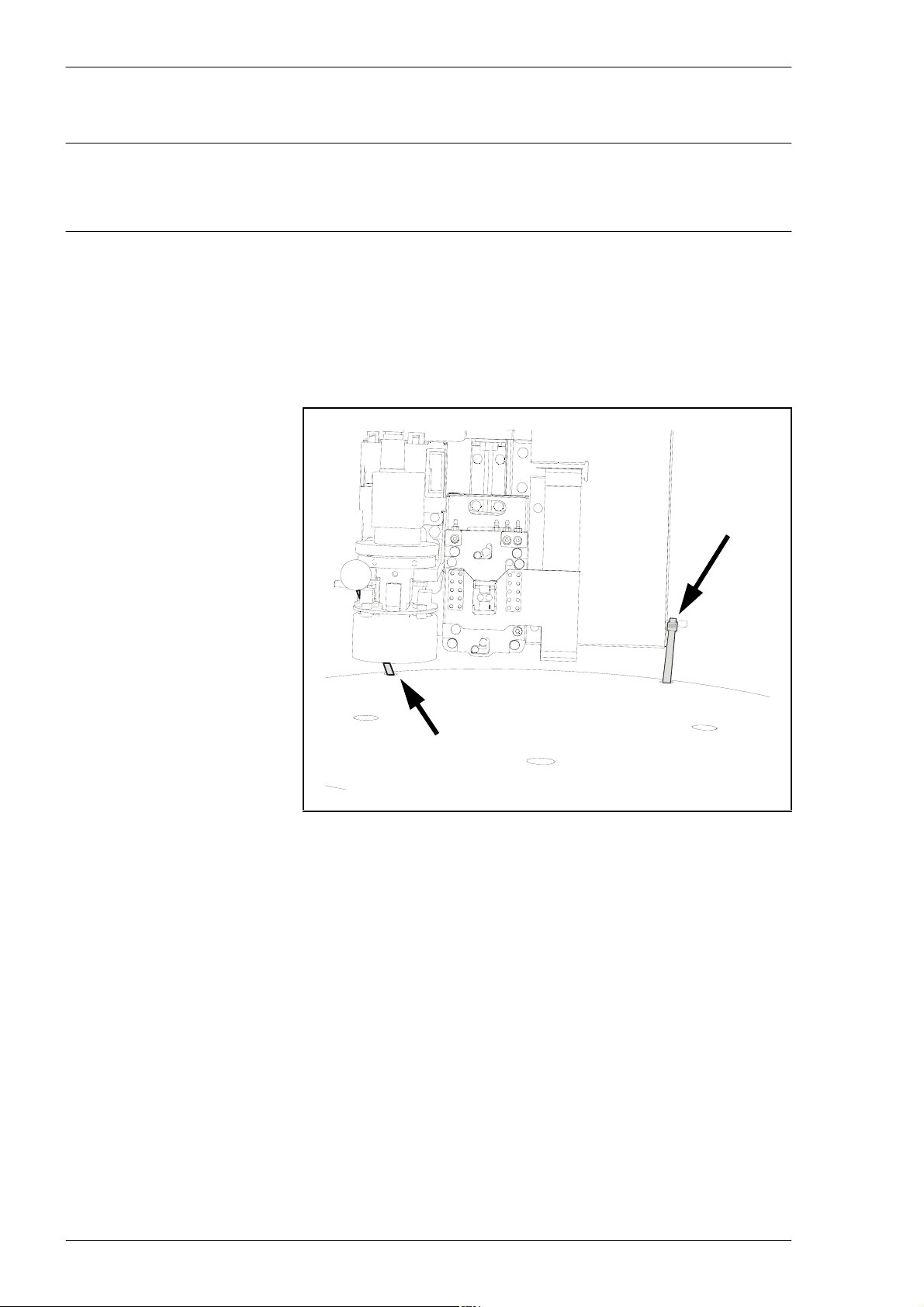
Whenever the machine is moved the Y beam and X wagon must be locked.
Remove the locks as follows:
1. Cut off and remove the cable ties holding the X wagon.
Figure 2-17. Cable ties.
2 - 20 Rev. 0003 2008-06 P-030-0014-EN – Service Manual
Page 45
MYDATA MY500 JetPrinter Installation
2. Pull the Y beam slighltly forward, and remove the lock, see 2-18.
Figure 2-18. Transport lock.
The lock is placed behind the bottom magnet on the Y beam, but in frot
of the conveyor.
Figure 2-19. Transport lock.
P-030-0014-EN – Service Manual Rev. 0003 2008-06 2 - 21
Page 46

Installation MY500 JetPrinter MYDATA
Software Installation
When the machine has arrived at its location in the workshop, it is time to do
software installation procedures. These procedures are described in a separate
installation guide.
Optional Equipment
Optional equipment, like for instance the manual load table, are provided with
their own installation guides.
2 - 22 Rev. 0003 2008-06 P-030-0014-EN – Service Manual
Page 47

MYDATA MY500 JetPrinter Machine Systems
3. Machine Systems
This chapter contains brief descriptions of the various systems that make up
the MY500 JetPrinter machine. The object is to give an orientation rather than
an in-depth understanding of the systems. At the end of the chapter you will
find block diagrams.
MY500 JetPrinter
With a technique inspired from computer ink jet printers, solder paste is
printed, stencil less, on Printed Wiring Boards (PWBs). Applying solder paste
with this technique gives more opportunities to design and manufacture PCBs
in an inventive and flexible way. The jet printing process is controlled by
powerful software, which enables fast changeovers and last minute changes.
Jet Printing
The jet printing system is made up of three main parts: the printer itself, the
cassette and cartridge, and a computer offline terminal.
The printer itself is the machines foundation, which integrates the motion
system, the positioning system as well as production conveyers.
The cassette is the heart of the system and contains the solder paste cartridge
and a solder paste ejector. Its main function is to deposit solder paste onto the
PWB with help of a step motor. Ink jet technology (piezo technology) is used
to shoot droplets of solder paste onto the PWBs surface mount lands.
The offline terminal consists of a PC and software. The software is capable to
read CAD files and transfer them into actual machine layouts. Machine
movements are guided by a machine control software, acting on instructions
in the form of a machine programs (layouts).
Piezo technology
With piezo technology the paste is squeezed out of the nozzle by mechanical
pressure. This is made possible by a ceramic piezo crystal, which is also used
in lighters. Its shape changes when it is fed by voltage. This in turn creates
pressure on the paste channel, causing the paste to be expelled from the nozzle.
P-030-0014-EN – Service Manual Rev. 0003 2008-06 3 - 1
Page 48
Machine Systems MY500 JetPrinter MYDATA
MY500 JetPrinter Main Parts
11
8
3
2
4
5
9
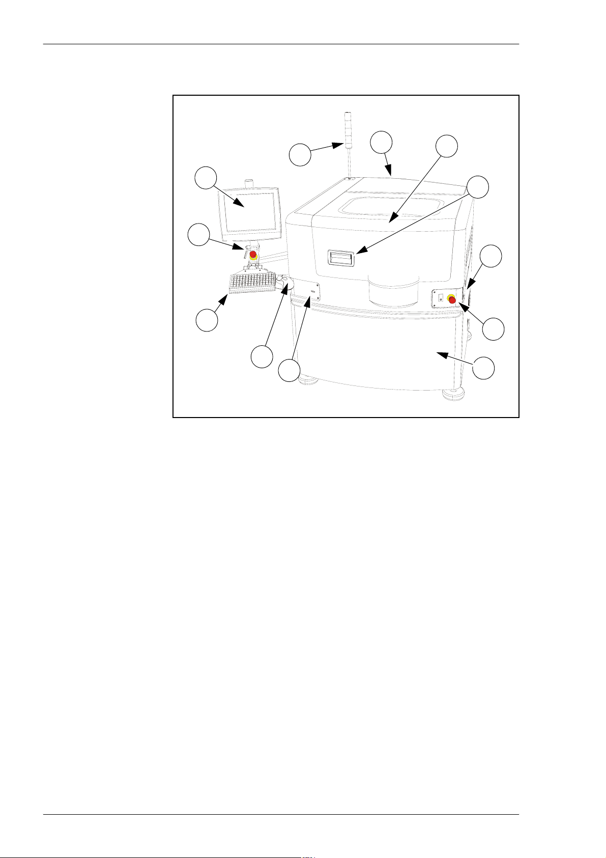
Figure 3-1. MY500 JetPrinter, components on the outside.
6
7
1
2
10
Outside:
1. Main switch.
2. Emergency stop buttons.
3. Touch screen.
4. Keyboard
5. Trackball
6. Front hood.
7. Front hood handle.
8. Light tower (optional).
9. USB port.
10. Front door. This door is locked.
11. Rear hood. This hood is fixed with four screws.
3 - 2 Rev. 0003 2008-06 P-030-0014-EN – Service Manual
Page 49
MYDATA MY500 JetPrinter Machine Systems
12
18
13
14
17
15
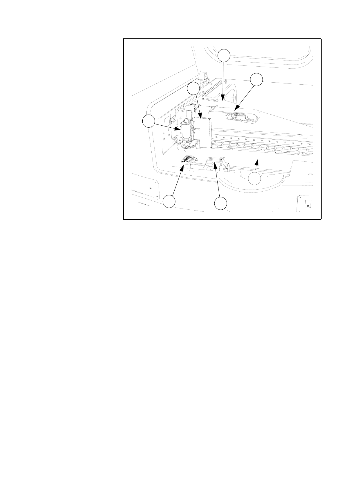
Figure 3-2. MY500 JetPrinter, components on the inside.
Inside:
12. Ybeam.
13. X wagon.
14. Solder paste cassette.
15. Camera calibration unit.
16. Cassette calibration unit.
17. Internal conveyor.
18. Electric cable harness.
16
P-030-0014-EN – Service Manual Rev. 0003 2008-06 3 - 3
Page 50
Machine Systems MY500 JetPrinter MYDATA
Inputs and Controls
A touchscreen is used to operate the machine. A keyboard and trackball are
used to input data, but can also be used to control machine operations if
desired.
On the screen operating status, messages and such are displayed. There is also
a signal tower which indicates the machines operational status.
Touch Screen
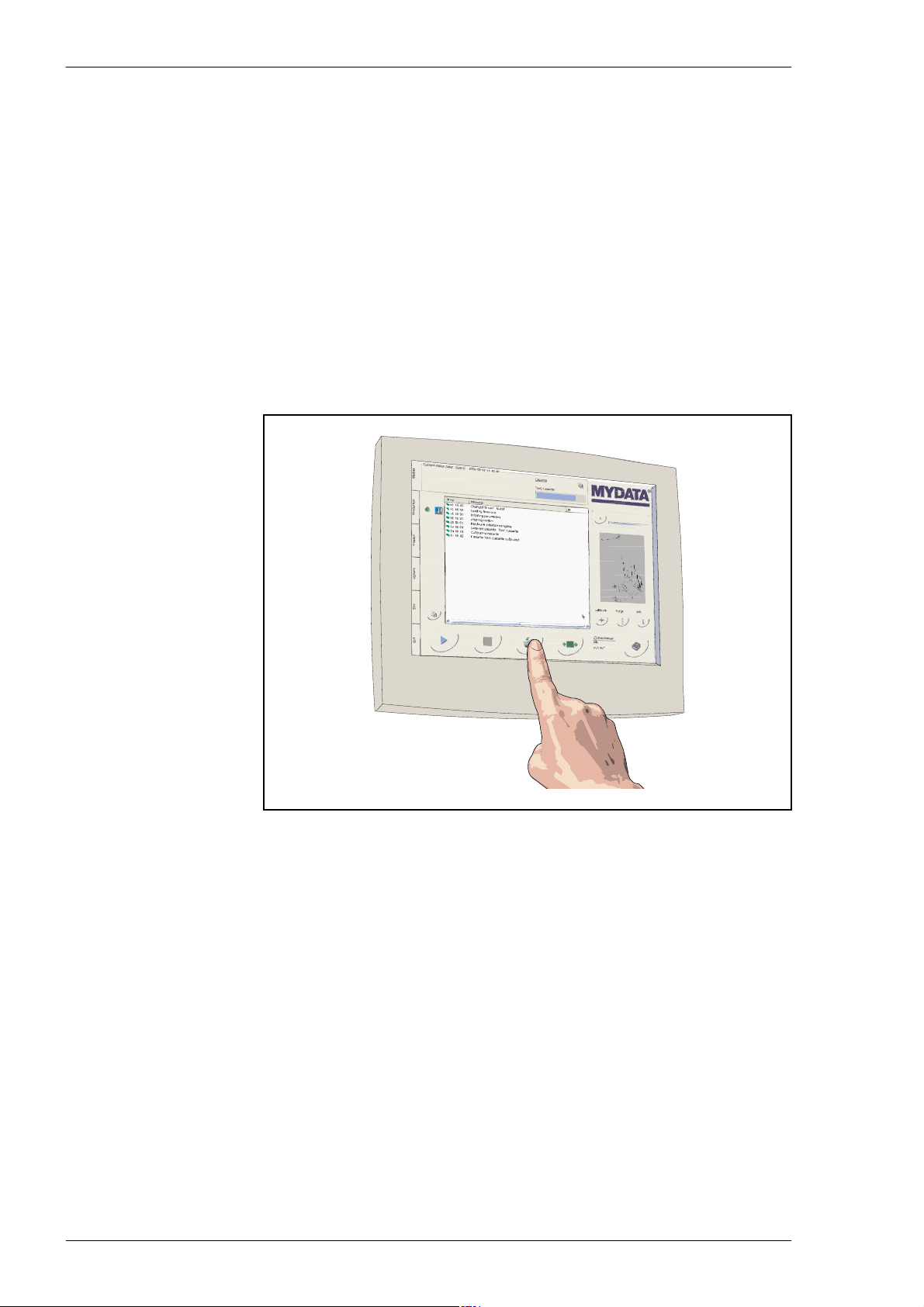
You can operate the MY500 JetPrinter machine by using the LCD (liquid
crystal display) touch screen. Functions such as start, stop, toggle and so on
are triggered when you touch the designated buttons on the screen with your
finger.
Figure 3-3. Touch screen.
Please read the following instructions carefully:
Tap the LCD touch screen gently; never use force.
Do not use a pen or any sharp object to tap the screen. This may damage the
surface.
Clean the LCD touch screen with a soft cloth. If needed, dampen the cloth
slightly before cleaning. Never use abrasives or cleaning solutions.
For adjustments and other information about the touch screen we refer you to
the OEM user’s guide.
3 - 4 Rev. 0003 2008-06 P-030-0014-EN – Service Manual
Page 51

MYDATA MY500 JetPrinter Machine Systems
Keyboard
A keyboard is provided with the MY500 JetPrinter. It acts as the standard input
tool for the JPSys software. It can also control the system in a normal
Windows way if so desired. For more information on how to use a keyboard
to control Windows we refer you to the Microsoft Windows help or user’s
guide.
Trackball
A trackball is provided for you to operate the standard mouse pointer on the
screen. In some windows this may be the most suitable alternative. The
trackball can also be used to control the system. In this case the system will
behave like any ordinary Windows program.
The trackball and keyboard cannot be disabled.
Barcode Scanner
A barcode scanner is provided for the registration of manufacturer's barcodes
on cartridges.
P-030-0014-EN – Service Manual Rev. 0003 2008-06 3 - 5
Page 52
Machine Systems MY500 JetPrinter MYDATA
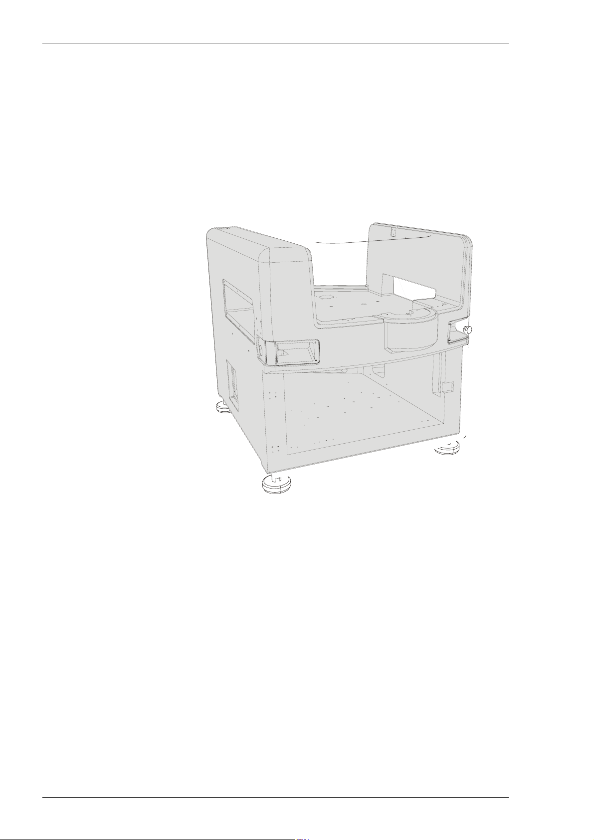
Framework
To be able to withstand high stresses, from accelerating movements, the frame
of the printer is made in a heavy stone-epoxy composite material . This is a
mineral casting mixed with epoxy. Mineral casting have outstanding
dampening, high rigidity and ensure dimensional accuracy.
The motion system, based upon a carbon fiber beam and two wagons, is
located inside the stone frame. An internal conveyor for the board movements
is also included. Finally there are hoods and doors attached to the framework
to cover the machine components.
Figure 3-4. Stone frame.
3 - 6 Rev. 0003 2008-06 P-030-0014-EN – Service Manual
Page 53
MYDATA MY500 JetPrinter Machine Systems
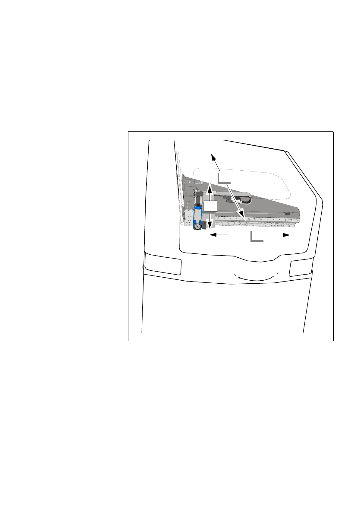
Movement Systems
The movement system is a three-dimensional system, based upon a carbon
fiber beam and two wagons. The motion system operates together with an
optic positioning system.
The machine contains the following movement systems:
• X movement moves the X wagon in the X direction.
• Y movement moves the Y beam in the Y direction.
• Z movement moves the cassette interface in the Z direction.
Y
Z
X
Figure 3-5. Y beam and X wagon.
P-030-0014-EN – Service Manual Rev. 0003 2008-06 3 - 7
Page 54
Machine Systems MY500 JetPrinter MYDATA
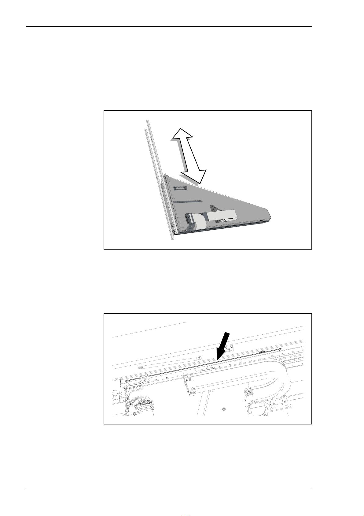
The Y Beam
The Y beam is a carbon fiber epoxy structure. This material has an
advantageous combination of good mechanical properties and low weight. It
is used for very stiff and light structures within sports equipment, aerospace,
and medical equipment. The beam perform all movements in the Y direction.
The beam is mounted on two linear guides on the machine frame. It is powered
by a magnetic, linear motor, see the The X Wagon section.
Figure 3-6. Y beam.
The accuracy of the beam's movement is ensured by the use of a linear encoder
system. This system use a linear scale on the frame and readheads on the beam.
Be careful not to scratch or otherwise damage the surface of the linear scale.
Scratching the surface may alter the machine's precision.
Figure 3-7. Y beam linear scale.
3 - 8 Rev. 0003 2008-06 P-030-0014-EN – Service Manual
Page 55
MYDATA MY500 JetPrinter Machine Systems
The X Wagon
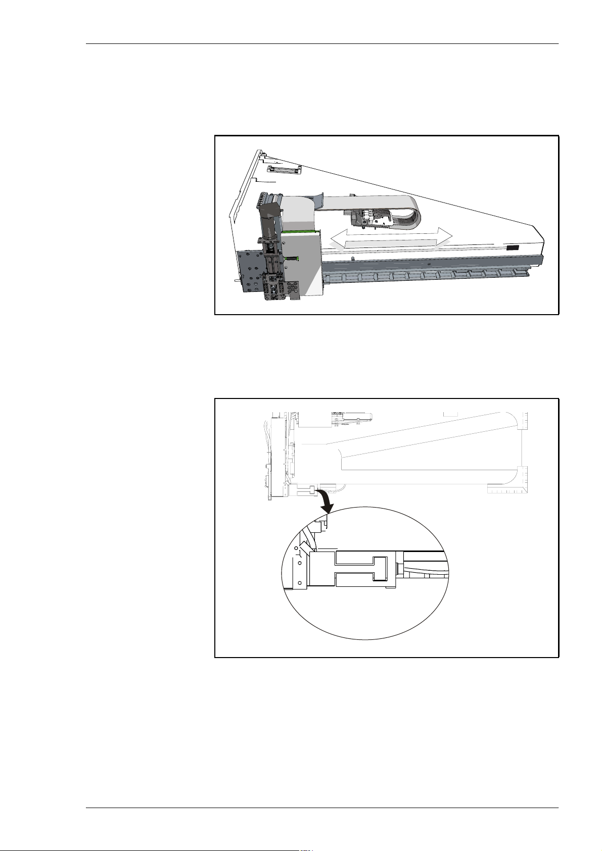
On the Y beam the X wagon is attached, which generates the X movements.
On the X wagon there is a solder paste cassette interface and a positioning
camera.
Figure 3-8. X wagon.
The X wagon is powered by a cog-free brushless linear motor, designed for
unlimited stroke (travel) servo applications. It produces smooth operation
without cogging.
Figure 3-9. Linear mo tor.
The linear servo motor consists of a U-formed stationary magnet track and a
moving coil assembly. The multi-pole magnet track is built up of alternating
polarity magnets bonded to a steel plate. The coil assembly must be centered
within the magnet track and guided by bearings.
P-030-0014-EN – Service Manual Rev. 0003 2008-06 3 - 9
Page 56
Machine Systems MY500 JetPrinter MYDATA
The X wagons positioning accuracy is, like the Y beam's, governed by a linear
encoder system. The linear scale for the X wagon is located on the Y beam.
Figure 3-10. X wagon linear scale.
CAUTION! Be careful not to scratch or otherwise damage the surface of the
linear scale. Scratching the surface can alter the machine's precision.
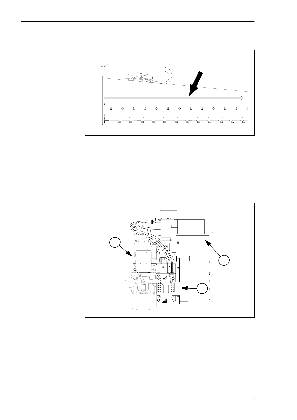
X wagon main parts
3
1
2
Figure 3-11. X wagon main parts.
On the X wagon plate the following main parts ar e found:
1. Circuit board hood.
2. Cassette interface.
3. Positioning camera.
3 - 10 Rev. 0003 2008-06 P-030-0014-EN – Service Manual
Page 57
MYDATA MY500 JetPrinter Machine Systems
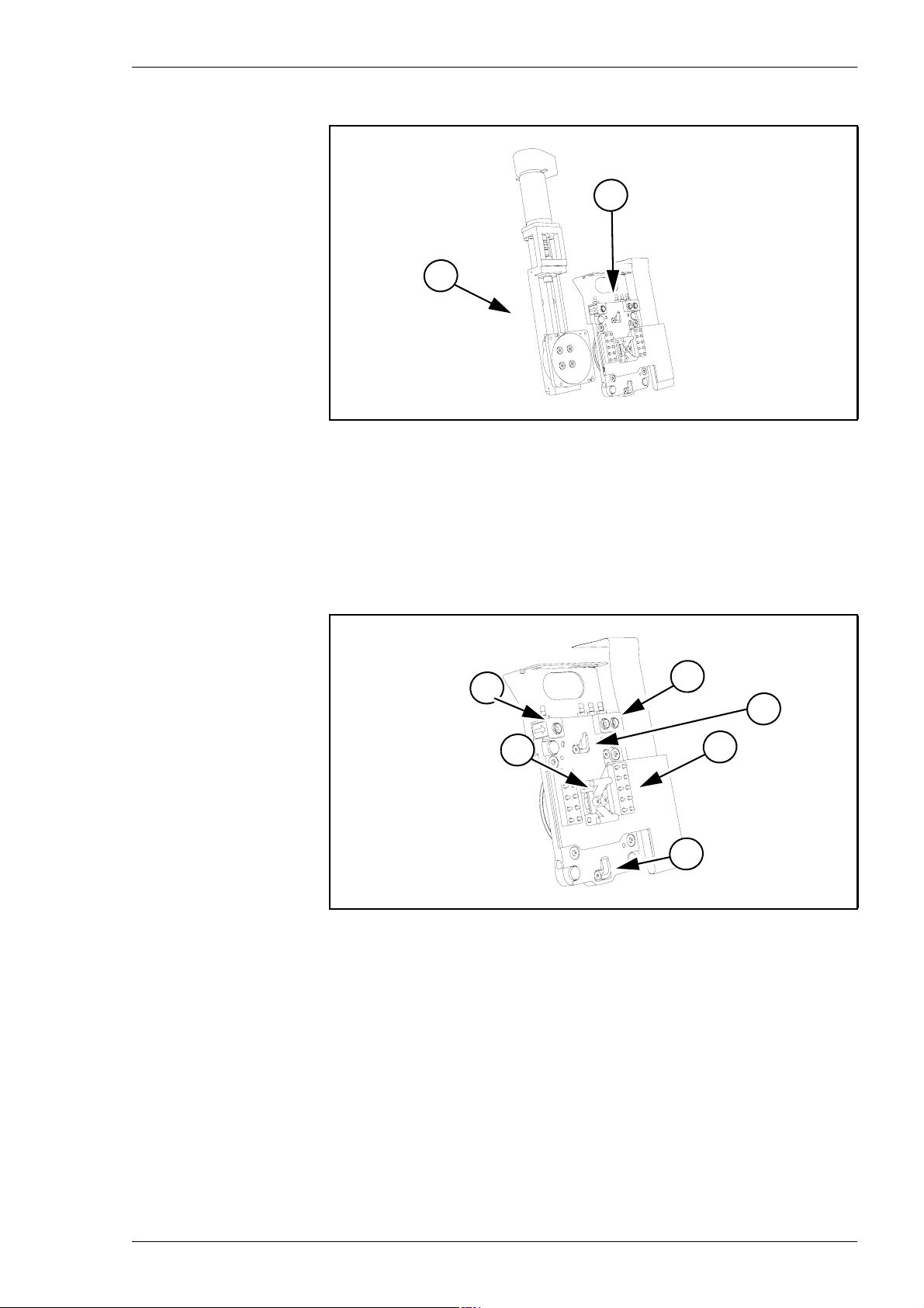
Cassette interface
1
2
Figure 3-12. Cassette interface main parts.
The cassette interface is divided into the following main parts:
1. Attachment unit.
2. Motor unit.
Attachment unit
2
1
2
4
3
Figure 3-13. Attachment unit main parts.
3
1. Attach claw.
2. Suction cups.
3. Steering blocks.
4. Circuit board.
P-030-0014-EN – Service Manual Rev. 0003 2008-06 3 - 11
Page 58
Machine Systems MY500 JetPrinter MYDATA
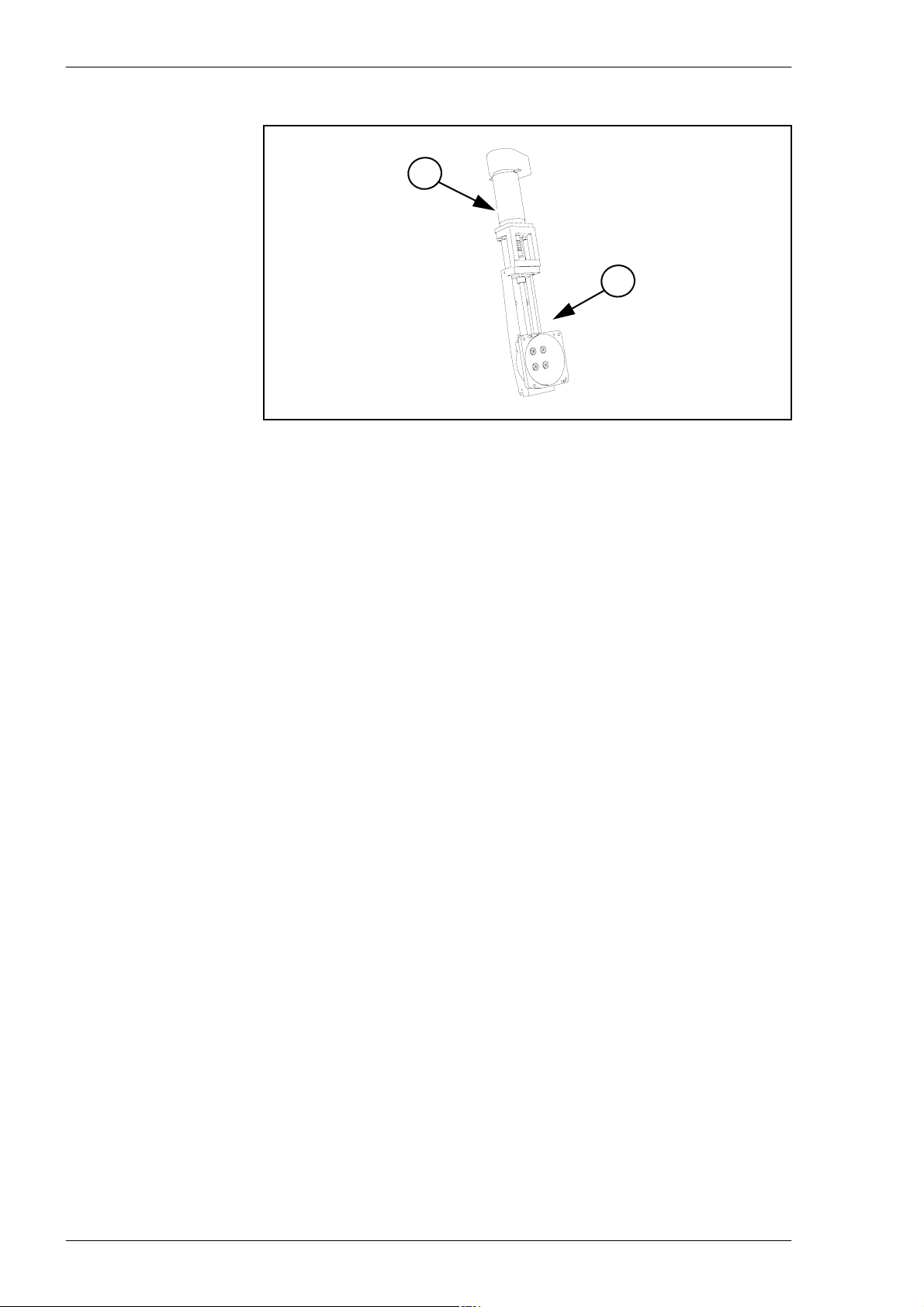
Motor unit
1
2
Figure 3-14. Motor unit main parts.
1. Motor unit.
2. Sleigh unit.
3 - 12 Rev. 0003 2008-06 P-030-0014-EN – Service Manual
Page 59
MYDATA MY500 JetPrinter Machine Systems
The Cassette
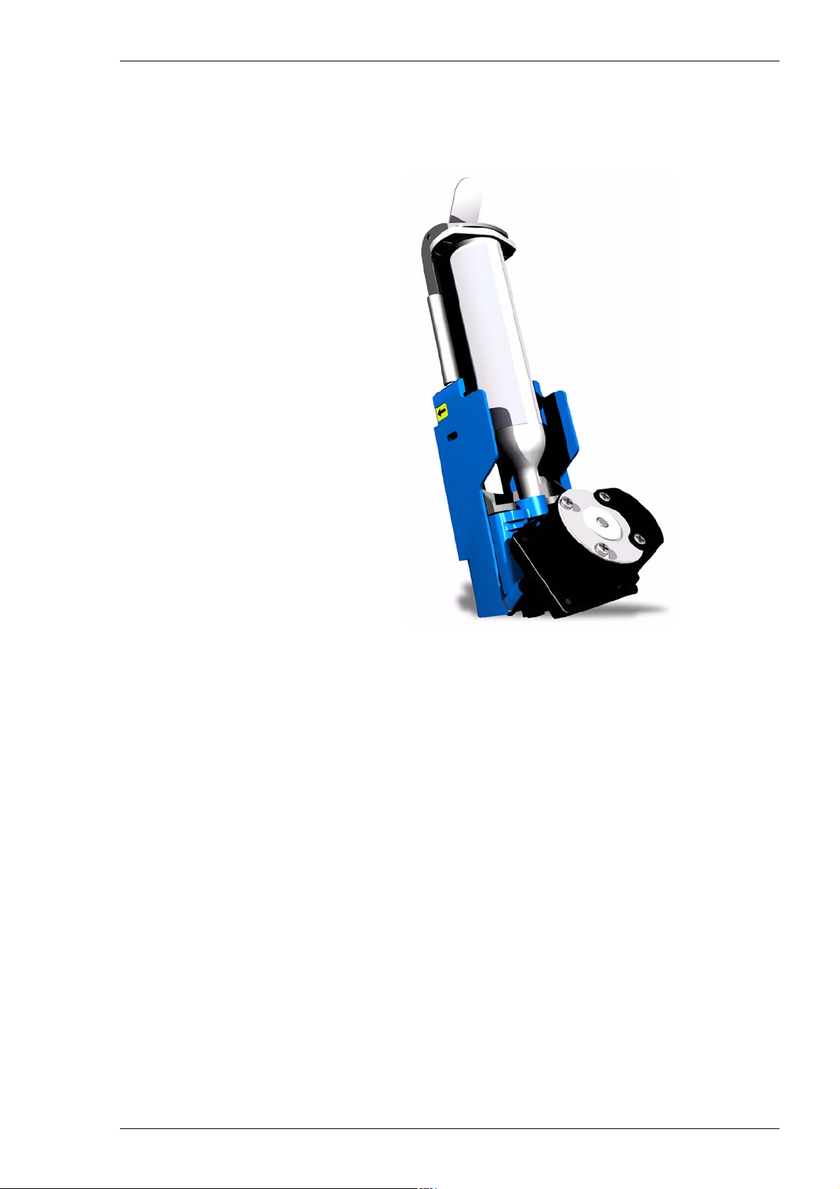
The solder paste cassette is made up of a holder with a motor assembly and a
paste cartridge.
Figure 3-15. Solder paste cassette.
On the backside of the holder you will find a circuit board which connects the
cassette and machine.
The cassette is a unit with intelligence. It has an electronic ID. The cassette
memory stores, paste type, selects machines settings, and enables fast change
overs of cassettes. This enables a switch from leaded paste to leadfree in
seconds.
The paste cartridge is inserted into the holder and locked in place with a
shackle. The motor will feed paste in to the ejector. In the ejector there is a
piezo unit which generates the force to eject solder paste. Paste spillage is
sucked into a filter box.
P-030-0014-EN – Service Manual Rev. 0003 2008-06 3 - 13
Page 60
Machine Systems MY500 JetPrinter MYDATA
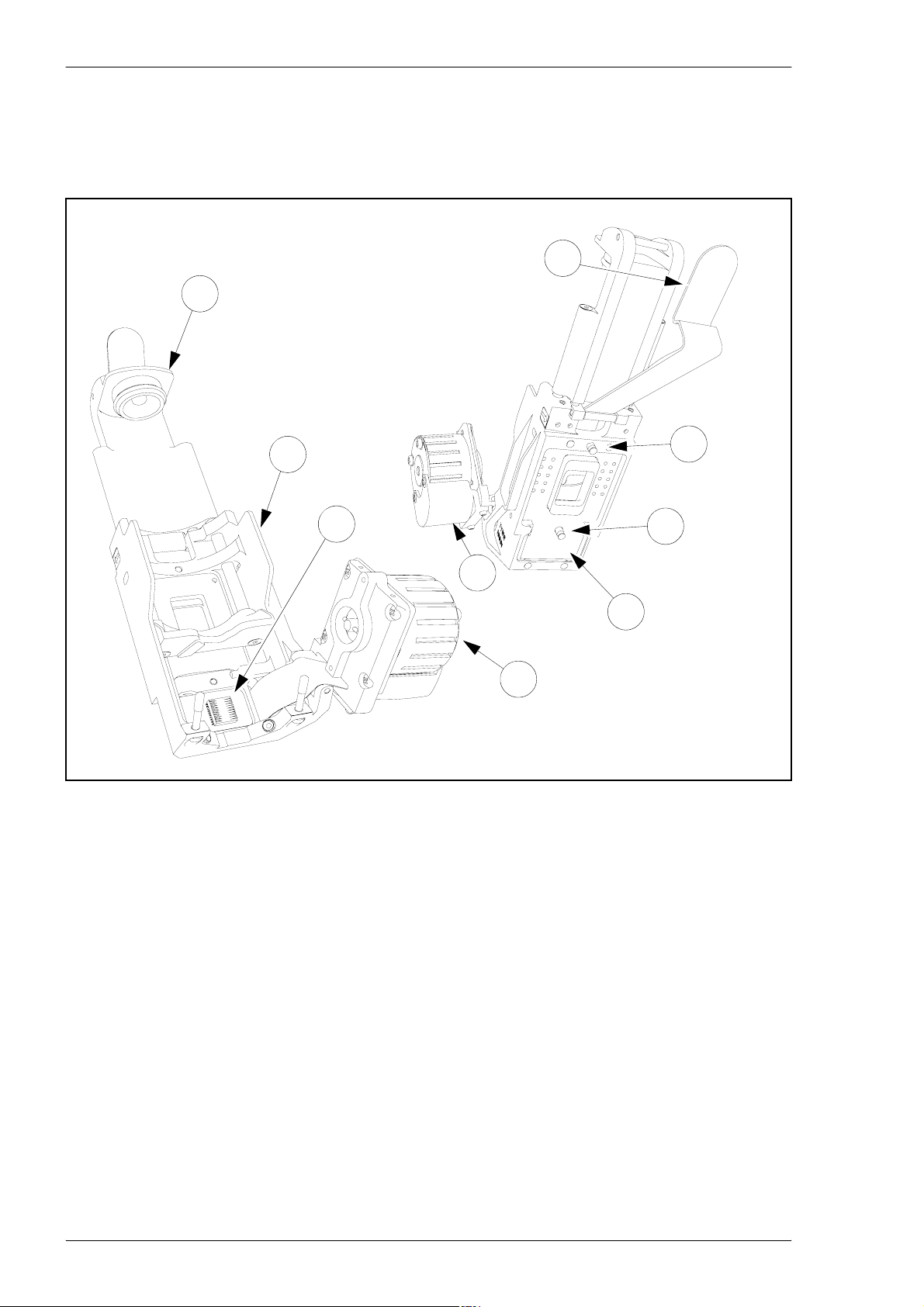
The holder assembly
The holder assembly is the carrier of the solder paste cartridge and the
interface between the machine and the cartridge. It carries the ejector assembly
and the motor unit.
1
2
3
4
6
5
Figure 3-16. Holder.
The holder have the following main parts:
1. Shackle
8
8
7
2. End piece.
3. Holder
4. Circuit board socket.
5. Motor assembly.
6. Connection cover.
7. Circuit board.
8. Steer pins.
3 - 14 Rev. 0003 2008-06 P-030-0014-EN – Service Manual
Page 61
MYDATA MY500 JetPrinter Machine Systems
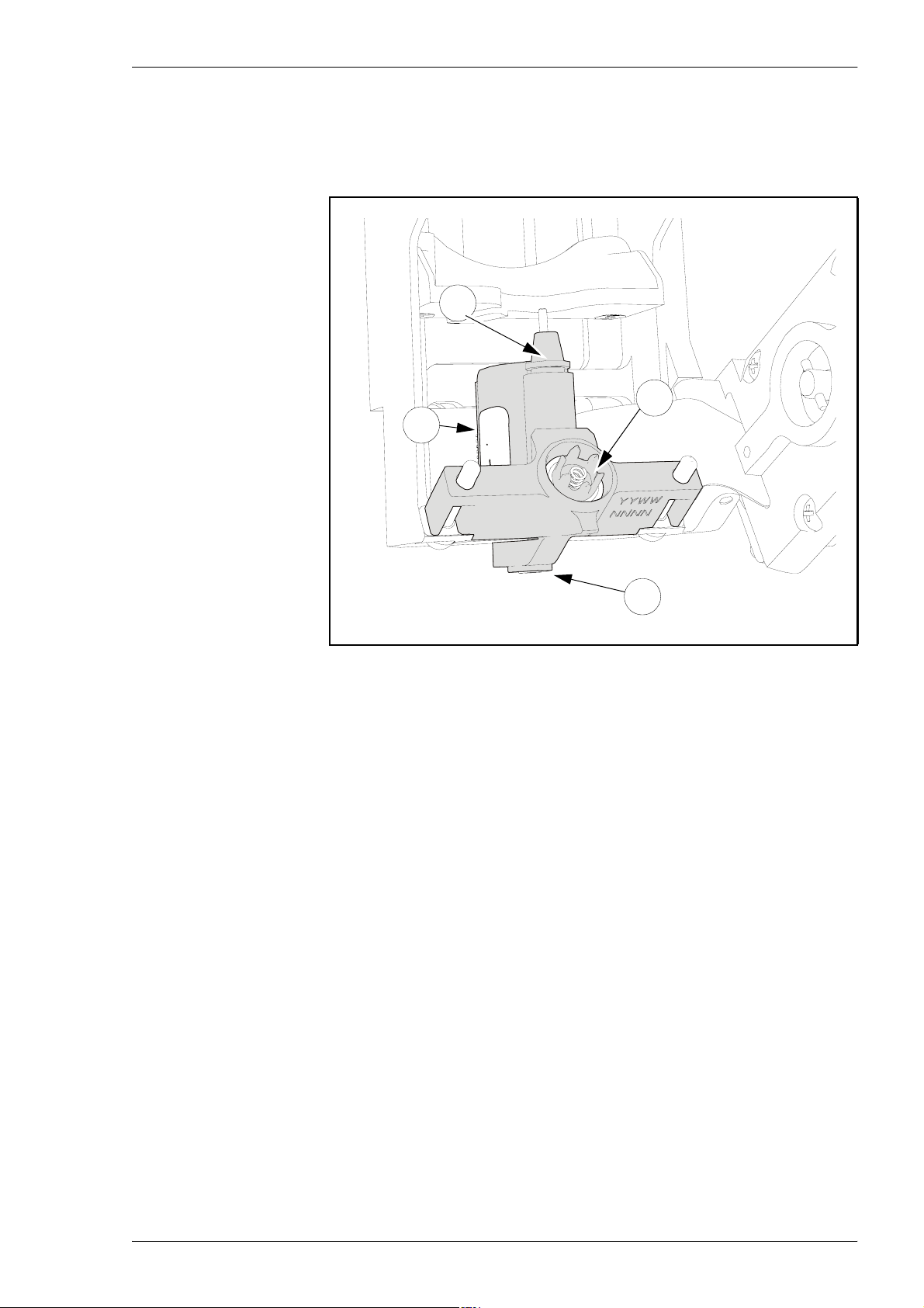
The ejector
The ejector is a wear part. It requires no internal cleaning or disassembling.
The ejector carry the piezo unit which generates the force needed to eject the
solder paste through the ejectors nozzle.
1
2
3
4
Figure 3-17. Ejector.
The ejector main parts are:
1. Filter box connector.
2. Feeder screw.
3. Piezo unit.
4. Nozzle
The principle is that solder paste is fed into a nozzle chamber by the feeder
screw. Voltage is applied to the piezo unit. The piezo hits a piston which ejects
the solderpaste.
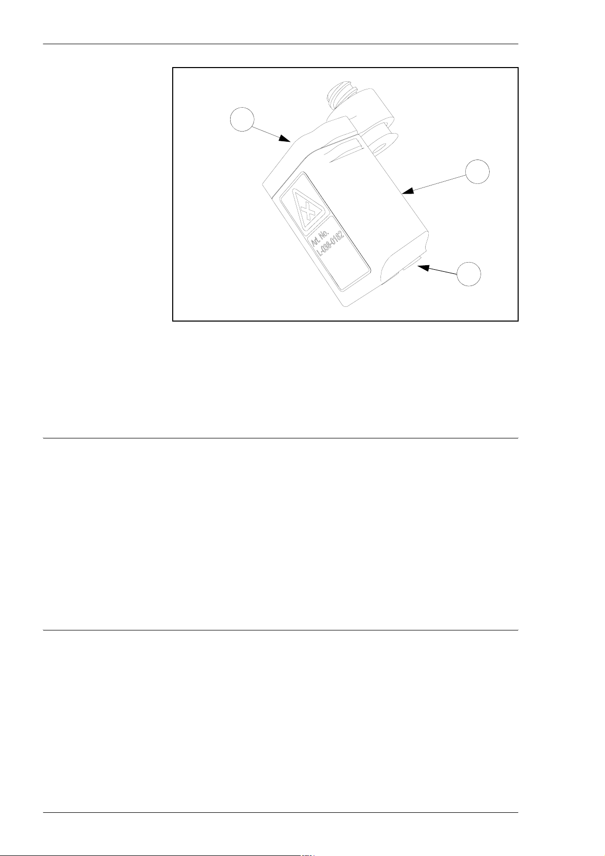
The filter box
The filter box function is to collect any waste solder paste. This will ensure
that the PWB is nor contaminated with solder paste in the wrong place. The
filter box is screwed on to the solder paste cartridge. It is applied before
installing the cartridge into the holder.
P-030-0014-EN – Service Manual Rev. 0003 2008-06 3 - 15
Page 62
Machine Systems MY500 JetPrinter MYDATA
1
2
3
Figure 3-18. Filter box.
The main parts of the filter box are:
1. Lid
2. Box
3. Suction cups.
WARNING! Solder paste, during handling or use, may be ha zardous to health
or the environment. Read the Material Safety Data Sheet and warning label
before using.
Always remember that care should be taken to avoid the ingestion of solder
paste. As solder paste often contains lead and/or other toxic materials, gloves
and gowns should be worn while using solder paste, and hands should be
washed afterwards.
Filter boxes contain solder paste and must be treated as hazardous waste.
Keep out of waterways.
Observe all label precautions.
3 - 16 Rev. 0003 2008-06 P-030-0014-EN – Service Manual
Page 63
MYDATA MY500 JetPrinter Machine Systems
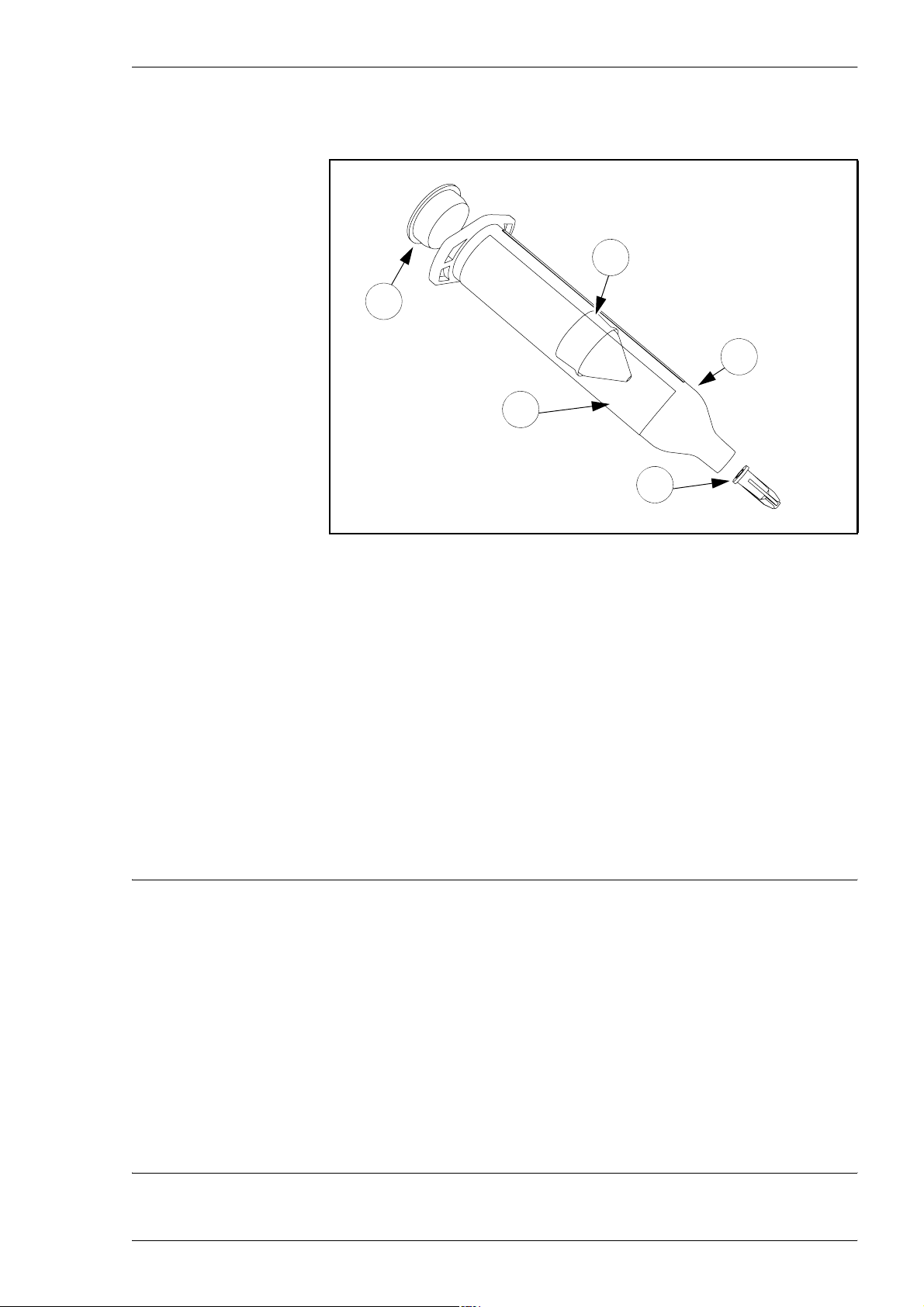
The solder paste cartridge
The solder paste cartridge is a disposable container that is discarded after use.
2
1
3
4
5
Figure 3-19. Solder paste cartridge.
It has the following main parts at delivery:
1. Cap (removed when installed into the holder). Used for transport and
storage when not in holder.
2. Plunger
3. Cartridge
4. Label
5. Threaded cap (removed when installed into the holder). Used for
transport and storage when not in holder.
On the cartridge there is a label stating product name, product number, product
group, and additional data according to J-STD-005. This information is
provided in plain text as well as Code 128 bar code.
WARNING! Solder paste, during handling or use, may be hazardous to health
or the environment. Read the Material Safety Data Sheet and warning label
before using. Always remember that care should be taken to avoid the
ingestion of solder paste. As solder paste often contains lead and/or other
toxic materials, gloves and gowns should be worn while using solder paste,
and hands should be washed afterwards.
Empty containers may contain product residue and must be treated as
hazardous waste.
Keep out of waterways.
Observe all label precautions.
P-030-0014-EN – Service Manual Rev. 0003 2008-06 3 - 17
Page 64
Machine Systems MY500 JetPrinter MYDATA
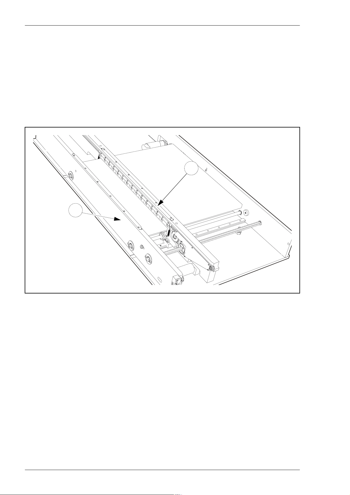
Conveyor
The board is transported into and out of the machine by an internal conveyor.
This is a top reference conveyor which accept cards with the following
specifications:
– Maximum PWB width and length: 508 × 508 mm.
– Minimum PWB width and length: 50 × 50 mm.
– Thickness: 0,4–7 mm.
– Maximum weight: 5 kg.
2
1
Figure 3-20. Internal conveyor.
The conveyor have one fixed side (’1’ in Figure 3-20) and one moveable side
(2) which adjusts the conveyor's width according to the loaded board.
The board is moved by conveyor bands running in the fixed and moving sides.
When the board reach the position where the machine will apply the solder
paste, a lifting table lift the board into position.
3 - 18 Rev. 0003 2008-06 P-030-0014-EN – Service Manual
Page 65
MYDATA MY500 JetPrinter Machine Systems
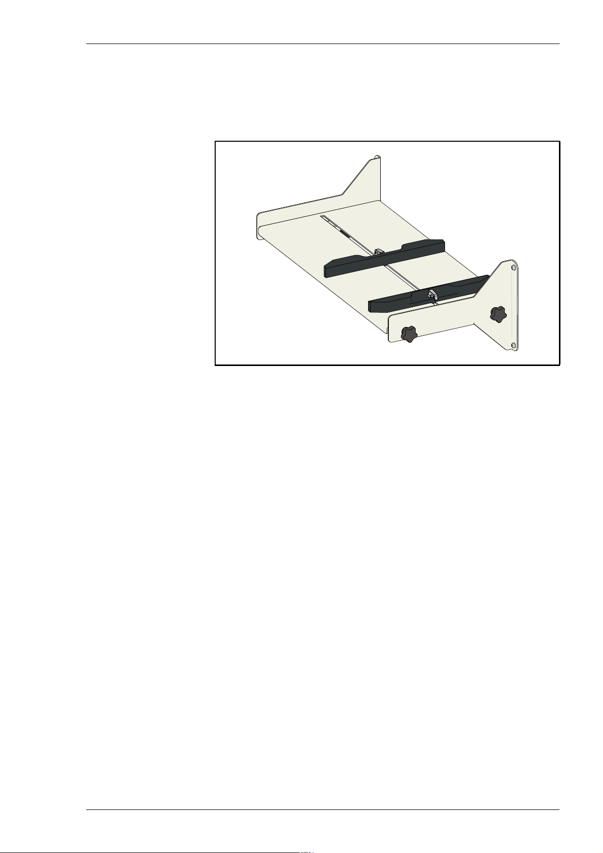
Manual Load Table
The intention is that the internal conveyor is connected to an external conveyor
system. As an option MYDATA have a manual load table for the cases where
an external conveyor system is not available.
Figure 3-21. Manual load table.
P-030-0014-EN – Service Manual Rev. 0003 2008-06 3 - 19
Page 66
Machine Systems MY500 JetPrinter MYDATA
Machine Electronics
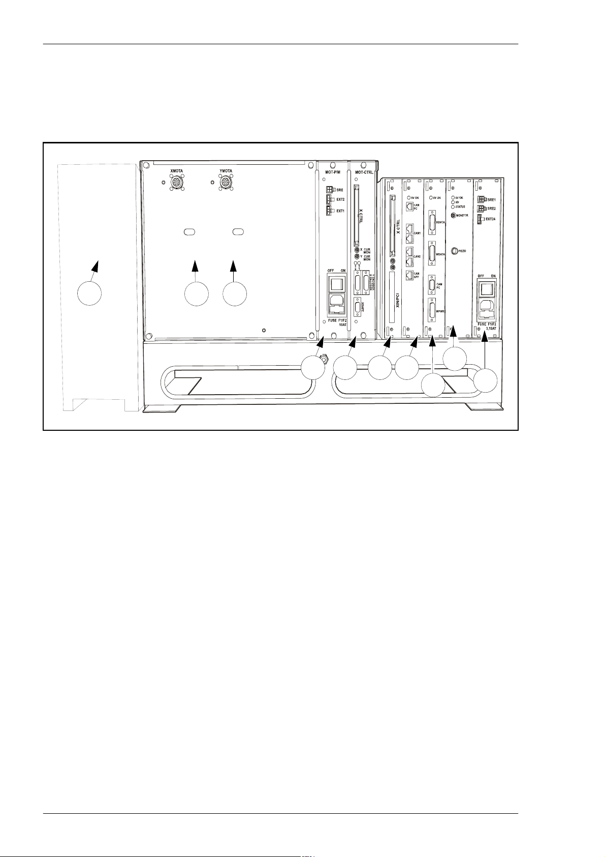
The following amplifier and control units are found in the machine behind the
front hood. Block diagrams describing these units are found in the next
section.
1
2
3
4
5
6
7
9
0
8
1
Figure 3-22. Machine electronic units.
Units:
1. PC
Runs the JPSys machine software. The PC has a motion controller board,
a CAN interface board and a video frame grabber board.
The Amplifier box with a passive backplane, MOT–PBP, which connects the
following boards:
2. X–AMP
Servo amplifier for the X – motor drive.
3. Y–AMP
Servo amplifier for the Y – motor drive.
4. MOT–PIM
Power input module. Converts AC power to 24 VDC, which is supplied
to the boards in the amplifier box through the MOT–PBP. Power is also
supplied to SAF–CAN boards in the safety loop including light tower
and air control electronics.
3 - 20 Rev. 0003 2008-06 P-030-0014-EN – Service Manual
Page 67

MYDATA MY500 JetPrinter Machine Systems
5. MOT–CTRL
Safety module which monitors the safety loop, and controls the X and Y
motor, conveyor, piezo drive, laser and stepper motor. External safety
switches can be added to the AUX EMERG connector on the back of the
machine.
The Control box with a passive backplane, CTRL–PBP, which connects the
following boards:
6. CTRL–INT
Motion controller interface. Connected to the PC's motion controller
board and connects the control box with the amplifier box.
7. CTRL–HUB
CAN network hub. Connected to the PC's CAN interface board. The
physical locations of the CAN bus nodes are:
– Cassette interface (XWG–BRD).
– Calibration station (SAF–CAN).
– Light tower (SAF–CAN).
– Air control (SAF–CAN).
– Piezo drive (CTRL–PZD).
– Conveyor (CB/CMOT)
8. CTRL–HIP
Head interface module. Signals and DC power to the X wagon.
Amplifier for the Z motor.
9. CTRL–PZD
Piezo drive module. Converts AC power to 100–200 VDC and generates
pulses for the piezo actuator.
10. CTRL–PIM
Power input module. Converts AC power to 24 VDC, which is supplied
to the boards in the control box through the CTRL–PBP. Safety relay for
the conveyor, piezo drive, laser and stepper motor power supply.
P-030-0014-EN – Service Manual Rev. 0003 2008-06 3 - 21
Page 68

Machine Systems MY500 JetPrinter MYDATA
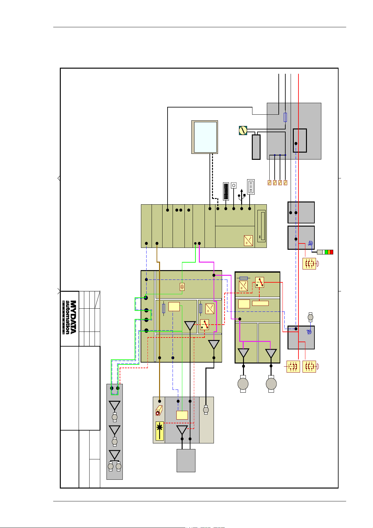
Block Diagrams
Below you will find block diagrams for the MY500 JetPrinter.
ZG-031-0046
This diagram provides an overview of the connection plate on the back of
the machine.
ZG-030-0013
This block diagram provides an overview of the electronic, safety and
pneumatic system. A short description of the different subsystems is seen
below:
– Cassette
The cassette subsystem includes a cassette, a piezo drive board
(CTRL-PZD), paste feed (XWG-BRD), and temperature (XWGBRD/SAF-CAN air control node) regulation. Communication
between units is done over CAN.
Power is supplied by the amplifier box for the SAF-CAN boards and
by the control box for the remaining boards. The piezo drive and
stepper are kept under control by the safety system. Dispensing is
triggered by an ’Event 0’ signal from the motion system (CTRL-INT).
– Motion
The motion subsystem includes a motion controller board, CTRLINT with controller interface, motors, encoders, CTRL-HIP with Zamplifier, amplifier box with X/Y amplifiers and safety circuitry.
–Sensor
The sensor subsystem includes a video frame grabber board and a
camera unit including the CAM-DIM board mounted on the X wagon.
Signal chain goes from the PC through CTRL-HIP and XWG-BRD to
the camera unit. Power is supplied by the control box. The laser is kept
under control by the safety system.
– Safety system
When an emergency stop button is pressed down the X and Y motors
will brake and the power is shut off. Power to the conveyor, piezo,
laser and stepper motor is also shut off. A safety switch in the front
hood, which will shut off the power to the devices mentioned above
when the hood is opened. External safety switches can be added to the
AUX EMERG connector on the back of the machine.
Safety relays are closed when all emergency stop buttons are released
and the front hood is closed. A control whether the safety loop is
closed and functional is done before the safety circuit is reset.
– Conveyor
The conveyor subsystem includes a conveyor with four motors
controlled by a CB/CMOT board communicating with software
through the PC's CAN interface board. Power is supplied by the
control box.
All schematics are found on the Documentations CD.
3 - 22 Rev. 0003 2008-06 P-030-0014-EN – Service Manual
Page 69
MYDATA MY500 JetPrinter Machine Systems
This document is our property. It must not be copied and its contents must not be imparted
to third persons without our written permission. Infringement of the above will be prosecuted.
LAN
200-230V AC
SMEMA SMEMA
Emergency
H:\Petter\blockschema\MY500 System.SchDoc
Approved
2008-06-10 PS
Designed
Drawn
2008-06-10
2008-04-28
JE
JE
Date Sign.
CAN interface
CTRL-HUB
Video Framegrabber
Network
1.6AT
DSP
COM2
COM1
RS485
Drive
Sound
CAN bus
PIEZO
Motion Controller
"Event"
CTRL-PZD
Touch
Screen
VGA
3.15AT (x2)
+24V
Monitor
Keyboard
Touch Screen
CTRL-INT CTRL-HIPCTRL-PIM
Control box
MAINS SWITCH
S1
Trackball
External USB
10AT (x2)
+24V
USB
scanner
DSP
TRANSFORMER
Barcode
DVD
Safety Relay
+24VS
Relay control
CAN bus
Monitor
PC
Control Box
MOT-PIM
MOT-CTRL
10AT
PC
Amplifier Box
Safety Loop and CAN bus
SAF-CAN SAF-CAN
Motor box
Control
SAF-CAN
SMINT-SAFCAN
BUTTON
KEYBOARD
EMERGENCY
Paper Feed
DC
Input box
Air
Conveyor
External
Tower
Light
S4 S2
Calib.
Unit
+24VS
X WAGON BOARD
Z Drive
DC
Z
X-Wagon
LINEAR
X
X-AMP
LINEAR
Y
Y-AMP
S3
HOOD SWITCH
BUTTON
MAIN
EMERGENCY
Part of
MY500 System Overview
Document number
ZG-030-0013
Title
Electronic System
Sheet Revision
()
6
CAN bus
Conveyor system
Width
DC
Transport
DC
Camera and Laser Ctrl.
CAN bus
Camera signal
STEPPER
Drive
LASER
"Event"
DSP
CASSETTE
00041
Lock
DC
DC
P-030-0014-EN – Service Manual Rev. 0003 2008-06 3 - 23
Page 70
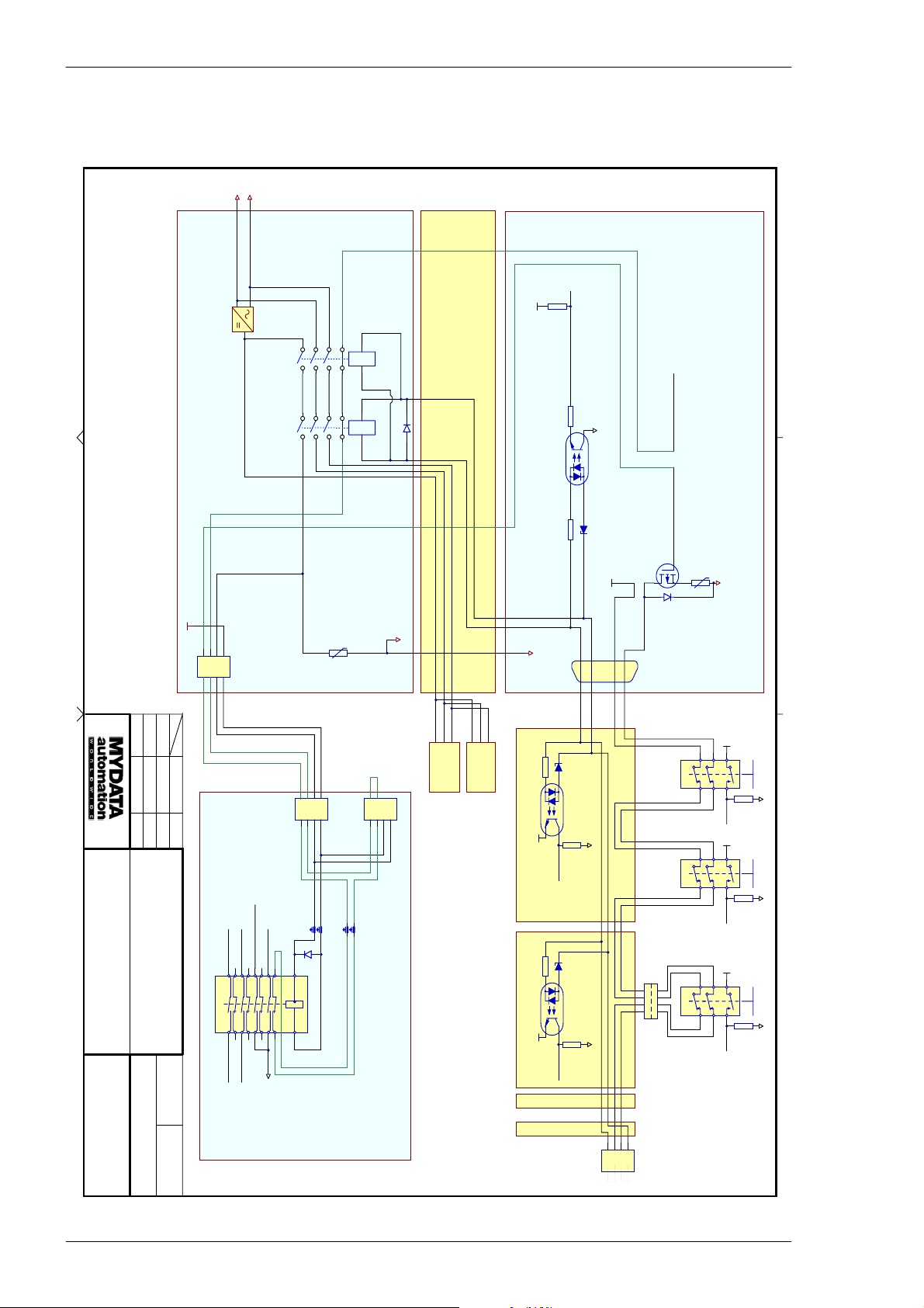
Machine Systems MY500 JetPrinter MYDATA
This document is our property. It must not be copied and its contents m ust not be imparted
to third persons without our written permission. Infringement of the above will be prosecuted.
N'
P'
H:\Petter\blockschema\System_Safety.SchDoc
Designed
Approved
2008-04-28
2008-06-10 PS
JE
Part of
MY500 System Overview
Drawn
Date Sign.
2008-06-10
JE
Title
System Safety
HResetLoop
LResetLoop
GND
4pole MINIFIT male
+24V_Relay
1234SRE
+24V
To Laser and
Stepper Motor
To Conveyor
+24V
SIM312-24V
SIM312-24V
4 pole MiniFit Jr
4
N'
7 8
2 1
7 8
2 1
N
+24V_Relay
Loop1
Loop2
RelayHi
RUE250
123
RelayLo
P'
9 10
9 10
P
PTC
SRE2
HResetLoop
3 4
3 4
HResetLoop
4 pole MiniFit Jr
SAFETY RELAY
5 6
SAFETY RELAY
5 6
Extension
4
1N4002
MOT-PIM
+24VS
Safety Relay
SRE1
123
+24V
+24V
AMP X
GND
pulled down by
2 x ULN2003 at CTRL-INT
/EStopped
MOT-CTRL
+24VS
GND
S2 S3 S4
XSAFE
Safety Loop Enable
PTC
ESTOP_BUTTON
RIGHT FRONT
MOT-PBP
120E
+5V
P
N
Vz = 10V
10k
HSafeRelay
LSafeRelay
+24VS
+24V
P
N
P
N
AMP Y
10k
GND
8
1
4
5
HSafeRelay
LSafeRelay
LSafe
HSafe
Vz = 10V
SAF-CAN (Calib. Station)
+5V
10k
Auxin0
GND
+5V
10k
Auxin4
HOOD
GND
+5V
10k
Auxin1
AC1
AC2
+24VS
Document number
ZG-030-0013
Sheet Revision
()
6
7 8
NAIS SF4-DC24V
1615
2019
AC_Line_R
AC_Line_S
To Piezo Amplifier
+24VS'
14
18 17
1
SAFETY RELAY2
13
2
910
56
1211
+24V
CTRL-PIM
SAF-CAN (LighTower)
GND
Vz = 10V
10k
Auxin4
GND
ESTOP_BUTTON
1
1
2
2
3
3
4
4
XMMIS
2x Mini-Fit
+5V
10k
MMI - module
+5V
10k
Auxin0
SMINT-SAFCAN
(MotorControl)
00042
SAF-CAN
(AirCtrl)
Optional safety
button extention
4 pole XLR
4
123
AUX EMERG
3 - 24 Rev. 0003 2008-06 P-030-0014-EN – Service Manual
Page 71
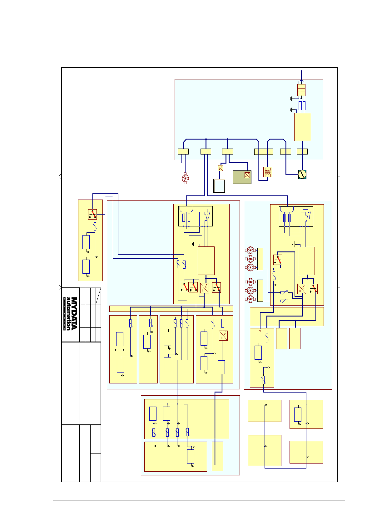
MYDATA MY500 JetPrinter Machine Systems
This document is our property. It must not be copied and its contents m ust not be imparted
to third persons without our written permission. Infringement of the above will be prosecuted.
EPN
1 phase
AC input
TB1
Input Power
PE
R
N
10AT
10AT
INPUT BOX
AC LINE FILTER
LINE
LOAD
N'
P'
H:\Petter\blockschema\System_Power.SchDoc
VOLTAGE REG
SWITCHER
Approved
2008-06-10 PS
Part of
MY500 System Overview
115/230 VAC
Vin Vout
+12V
Vin Vout
+5V
Designed
Drawn
2008-06-10
2008-04-28
JE
JE
Power System
PTC
CB
Date Sign.
Title
0.3A
+24V
CTRL-PBP
ISOLATED
DC/DC CONV
Vin
+Vout
-Vout
-12V
SWITCHER
Vin Vout
+5V
0.9A
+12V
PTC
SWITCHER
+24V
CTRL-INT
PTC
1.1A
+24V
Vin Vout
+5V
CTRL-HUB
VOLTAGE REG
Vin Vout
+5V
Z-AMP
F1/F2 2x3.15AT (H)
PTC3APTC
SPARE
PTC
2.5A
+24V_XPWR
+24V
AC3
FAN
123
LE3
N
PTC
2.5A
PTC
3A
3A
+24VS_XPWR
CTRL-HIP
+24V
+24VS
VOLTAGE REG
SWITCHER
4
EPN
LINE
LOAD
N'
Vin Vout
Vin Vout
1
2
P'
+24V
+18V
+5V
AC2
AC LINE FILTER
+12V
MONITOR
Touch
Screen
Switched & fused AC inlet
XACIN
CTRL-PIM
PTC
1.6AT
0.9A
120-374VDC
+24V
Pulse former
CTRL-PZD
Vin Vout
AC1
PC
CONTROL BOX
SWITCHER
+24VS
Vin Vout
3A
FAN UNIT
FAN SHELF
3A
+5V
PTC
XTEN
TRANSFORMER
115/230VAC
F1/F2 2x10AT (H)
PTC
RUE250
+24VS
PTC
PTC
PTC
MOT-CTRL
+24V
N
RUE250
RUE250
X-AMP
XFMPS
123
LE3
Y-AMP
4
EPN
LOAD
LINE
+24V
XTMPS
S1
1
2
N'
P'
MAINS SWITCH
Switched & fused AC inlet
XACIN
MOTOR BOX
MOT-PIM
AC LINE FILTER
MOT-PBP
SAF-CAN
Document number
ZG-030-0013
Sheet Revision
()
6
00043
SWITCHER
0.5A
Vin Vout
+5V
PTC
+5V
VOLTAGE REG
Vin Vout
+15V
0.3A
PTC
+15V
0.3A
+24V
PTC
+24V
0.3A
PTC
VOLTAGE REG
Vin Vout
+24VS
+5VS
CAM-DIM
Piezo pulse voltage
XWG-BRD
XWG-ZFX
+24V
AIR
CONTROL
VOLTAGE REG
Vin Vout
X-WAGON
+5V
SMINT-SAFCAN
+24V
MOTOR
CONTROL
+24V
+24V
CALIBRATION LIGHT
UNIT TOWER
SAF-CAN
SAF-CAN
P-030-0014-EN – Service Manual Rev. 0003 2008-06 3 - 25
Page 72
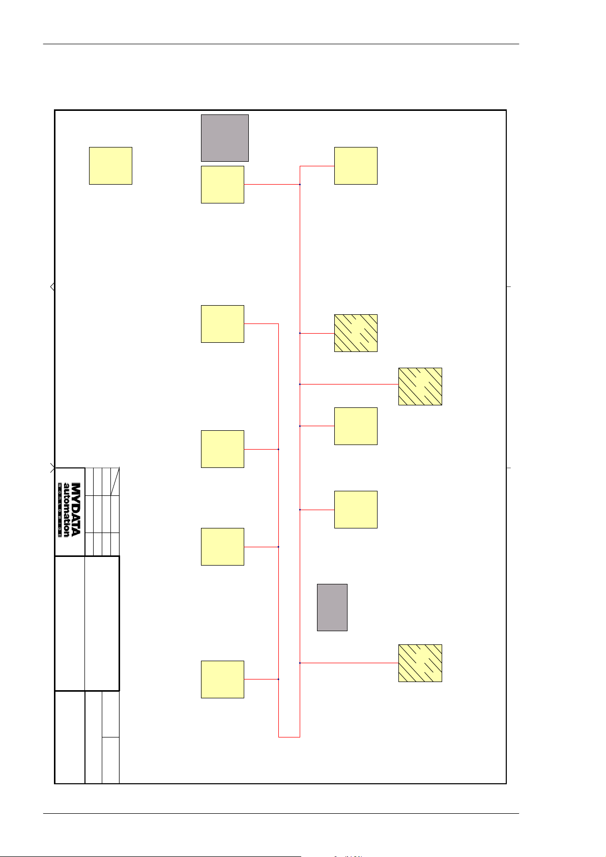
Machine Systems MY500 JetPrinter MYDATA
This document is our property. It must not be copied and its contents m ust not be imparted
to third persons without our written permission. Infringement of the above will be prosecuted.
4 uLAN_PBP
5 uLAN_PIM
1 uLAN_INT
2 uLAN_HUB
3 uLAN_HIP
(node 10)
EEPROM channels
H:\Petter\blockschema\System_CANnodes.SchDoc
ULAN channel 7, computer board EEPROM (only from PC)
Special functions
ULAN channel 6, mother board EEPROM (only from PC)
(C32 DSP)
7 - Power +5V
6 - Power +24V
Analog inputs
Generic MY500 node
Analog outputs
0 - Paste pressure
Special functions
Piezo pulse generator
5 - Auxout total current
0 - High voltage DC output control (only f rom DSP)
1 - Pulse slope control
4 - I/O power +24V
1 - Fan current
2 - Filterbox air flow surveillance
Analog outputs
Analog inputs
0 - (Air pressure warning)
Piezo
2 - Pulse output current
3 - Pulse output voltage
4 - Peak current
5 - Power +18V
AirCtrl
3 - Cassette unlock
4 - X motor cooling
5 - Y motor cooling
ExtConvCtrl
1 - AC line voltage
2 - Cassette cooling
0 - High voltage DC input
1 - Cassette lock
Analog inputs
0 - Filterbox air flow
C32 DSP
7 - Red LED control
Digital outputs
Digital outputs
4 - /EActivate
2 - (Filterbox air flow surveillance)
4 - EStop
5 - Auxout0 readback
8 - EStopped
1 - 5 CTRL-BOX EEPROM connections
1110 13 12
1 - (Fan current)
0 - Air pressure warning
Digital inputs
Digital inputs
PWM cassette heater
ULAN channel 5, holder EEPROM (only f rom PC)
Stepper velocity controller
Special functions
ULAN channel 4, ejector EEPROM (only from PC)
Analog outputs
3 - Stepper peak current limit (only from DSP)
Not populated
C32 DSP
5 - Power +15V (camera)
4 - Power +24V (stepper)
IXXAT
1 - Cassette temperature
2 - X encoder quality signal
Analog inputs
0 - X motor temperature
04
-
CassetteInterface
Digital inputs
8 - Paste level (not implemented)
9 - Cassette position (not implemented)
PC
CAN-HUB
Conveyor NextMovePCI
CMOT
CAN Kingdom
Designed
Approved
Drawn
Date Sign.
2008-06-10
2008-04-28
2008-06-10 PS
JE
JE
Part of
MY500 System Overview
Document number
ZG-030-0013
Title
CAN Network
Node Functional Description
Sheet Revision
()
6
00044
4 - I/O power +24V
5 - Auxout total current
Analog inputs
5 - SMEMA downstream
5 - Auxout total current
LightTower
Digital outputs
0 - Red lamp
1 - Yellow lamp
3 - White lamp
2 - Green lamp
4 - SMEMA upstream
CalibStation
Digital outputs
Analog inputs
0 - Paper motor enable
4 - I/O power +24V
5 - Auxout0 readback
4 - EStop
5 - Auxout0 readback
8
1 - RS485 RXD
4 - EStop
2 - SMEMA upstream
3 - SMEMA downstream
3 - Height indicator
1 - Hood safety switch
(big red @ machine right)
Digital inputs
0 - RS485 TXD
Digital inputs
1 - Safety button (big red @ keyboard)
Digital inputs
0 - Safety button
3 - CANPower
4 - FanMonitor1
5 - FanMonitor2
Analog inputs
2 - HSafeMonitor
0 - X_encSetup
1 - Y_encSetup
2 - AmpReset
(node 7)
4 uLAN_MPBP
5 uLAN_MPIM
0 - AmpMuxX
1 - AmpMuxY
EEPROM channels
Digital Outputs
4 - 7 MOT-BOX EEPROM connections
MotorControl
7
Digital inputs
0 - RS232 TXD
1 - RS232 RXD
Baldor
Connection to comms array, SDO index 0x2000
2
Special functions
3 - 26 Rev. 0003 2008-06 P-030-0014-EN – Service Manual
Page 73
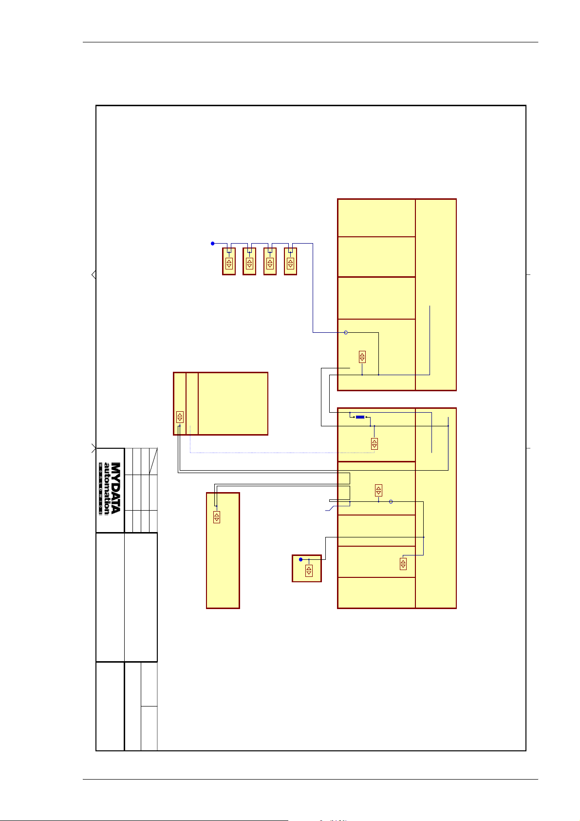
MYDATA MY500 JetPrinter Machine Systems
This document is our property. It must not be copied and its contents m ust not be imparted
to third persons without our written permission. Infringement of the above will be prosecuted.
H:\Petter\blockschema\System_CANnetwork.SchDoc
Designed
Approved
2008-04-28
2008-06-10 PS
JE
Drawn
Date Sign.
2008-06-10
JE
Motion Control Board
CAN Control Board
Termination
Air Control
Conveyor
External Conveyor Control
Calibration Station
Light Tower
PC
NextMovePCI (TTL level)
CAN_C
CANSPY
CAN_A
AMP X
AMP Y
MOT-PIM
MOT-CTRL
CAN_C
CTRL-INT
CTRL-HUB
Termination
Optional
JUMPER
CAN_A
CAN_D
Optional
Termination
CAN_C
MOT-PBP
CTRL-BOXMOT-BOX
CAN_A
CAN_C
CAN_D
Part of
MY500 System Overview
and Termination
Title
CAN Network Routing
X-WAGON
Termination
CAN_D
CTRL-HIP
CTRL-PZD
CAN_D
CRTL-PBP
CRTL-PIM
Document number
ZG-030-0013
Sheet Revision
()
6
00045
P-030-0014-EN – Service Manual Rev. 0003 2008-06 3 - 27
Page 74
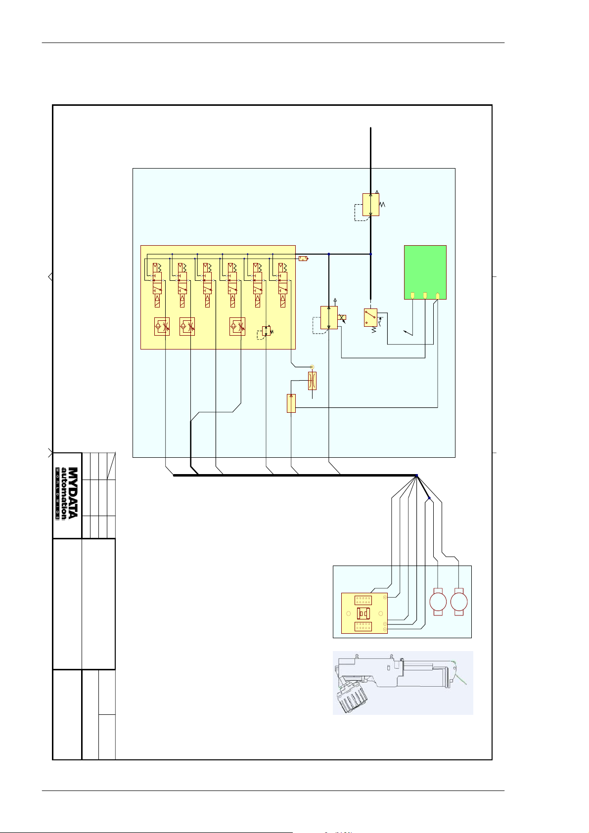
Machine Systems MY500 JetPrinter MYDATA
This document is our property. It must not be copied and its contents m ust not be imparted
to third persons without our written permission. Infringement of the above will be prosecuted.
0,8 - 1,0 MPa
AIR IN
H:\Petter\blockschema\System_Pneumatic.SchDoc
Designed
Approved
2008-04-28
2008-06-10 PS
Drawn
Date Sign.
2008-06-10
5
CONTROLLER
SPEED
Y-COOL (Nr.7)
SPEED
CONTROLLER
X-COOL (Nr.6)
COAXIAL TUBE
CASSETTE-OPEN (Nr.3)
1
31213221332134213
CONTROLLER
SPEED
CASSETTE-COOL (Nr.5)
REGULATOR
CASSETTE-LOCK (Nr.1)
FLOW SENSOR
PR
21302
VALVE CPL.
VACUUM (Nr.2)
SILENCER
2
EP-REGULATOR
VACUUMPUMP
1
3
PASTE-PRESSURE (Nr.4)
CABLECHAIN
REGULATOR
PRESSURE SENSOR
XAOUT
XDOUT
valve 0-5 control
pin 2
CONNECTION PLATE CPL.
SAF-CAN boar d
XDIN
pin 1
pin 3
JE
JE
Part of
MY500 System Overview
Document number
ZG-030-0013
Title
Pneumatic System
Sheet Revision
()
6
00046
Cassette Interface
CASSETTE-LOCK (Nr.1)
VACUUM (Nr.2)
CASSETTE-OPEN (Nr.3)
CASSETTE-COOL (Nr.5)
PASTE-PRESSURE (Nr.4)
Y-COOL (Nr.7)
X-COOL (Nr.6)
X
LINEAR
LINEAR
X/Y-WAGON
Y
3 - 28 Rev. 0003 2008-06 P-030-0014-EN – Service Manual
Page 75
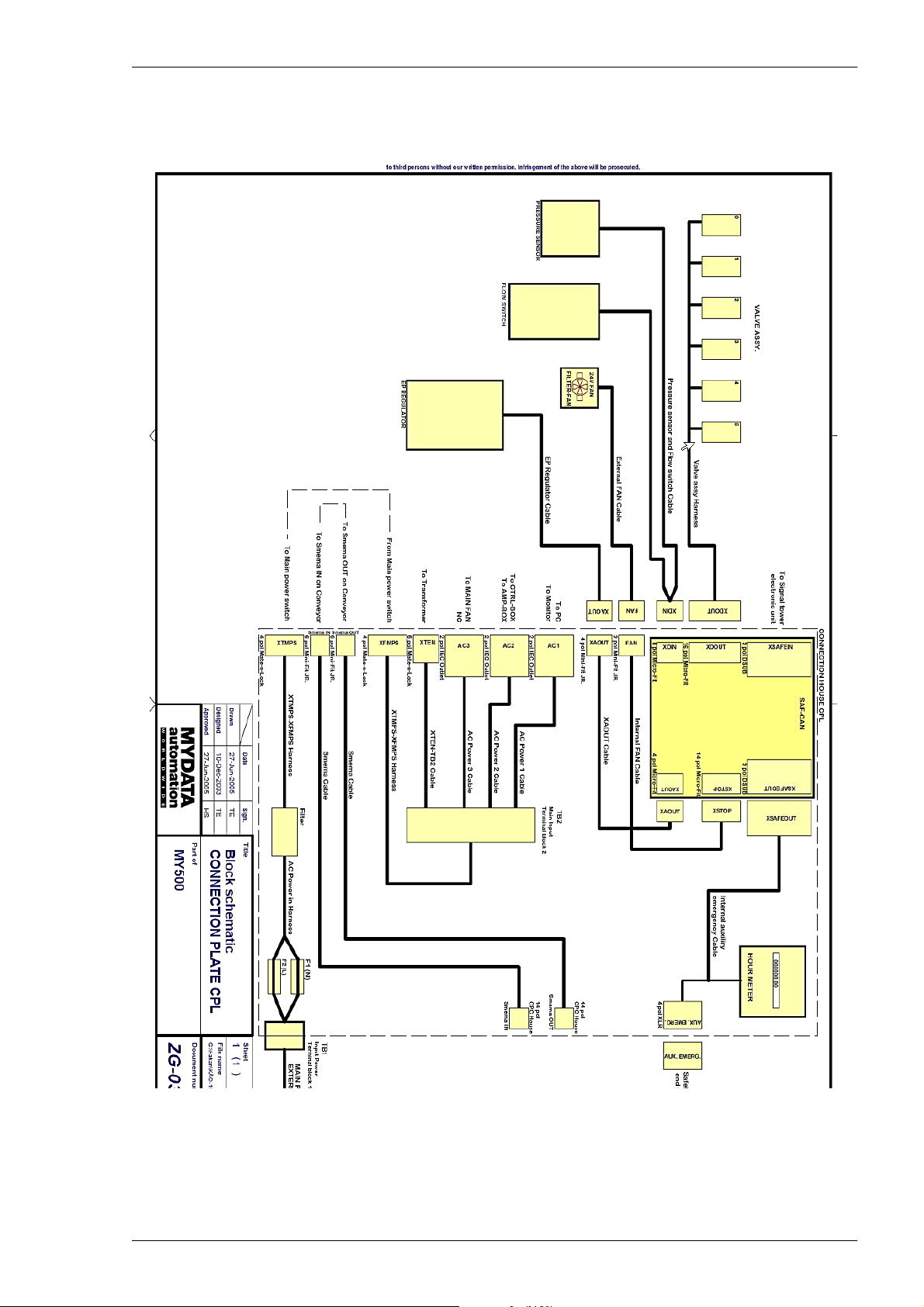
MYDATA MY500 JetPrinter Machine Systems
P-030-0014-EN – Service Manual Rev. 0003 2008-06 3 - 29
Page 76

Machine Systems MY500 JetPrinter MYDATA
3 - 30 Rev. 0003 2008-06 P-030-0014-EN – Service Manual
Page 77
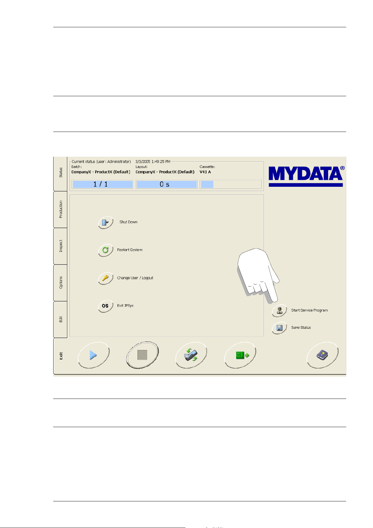
MYDATA MY500 JetPrinter Adjustments
4. Adjustments
The JPSys system includes a service system. This is a tool used to calibrate and
adjust the machine systems. In this manual we will not describe the service
system. This chapter is only a brief orientation.
WARNING! The service system is intended as a tool for authorized service
engineers only. Adjustments may only be performed by au tho r ized pe rso nnel!
The service system is started from the Exit window.
Figure 4-1. Exit window.
The machine must always be re-calibrated after it has been moved.
P-030-0014-EN – Service Manual Rev. 0003 2008-06 4 - 1
Page 78
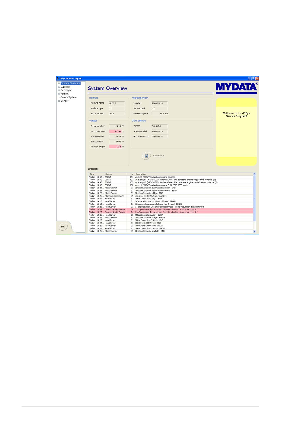
Adjustments MY500 JetPrinter MYDATA
System Overview
When you start the service system you will get a system overview, see
Figure 4-2. You are shown information about the machine and its software.
In a listing to the left you can select the systems you would like to test.
Figure 4-2. The system overview screen.
4 - 2 Rev. 0003 2008-06 P-030-0014-EN – Service Manual
Page 79
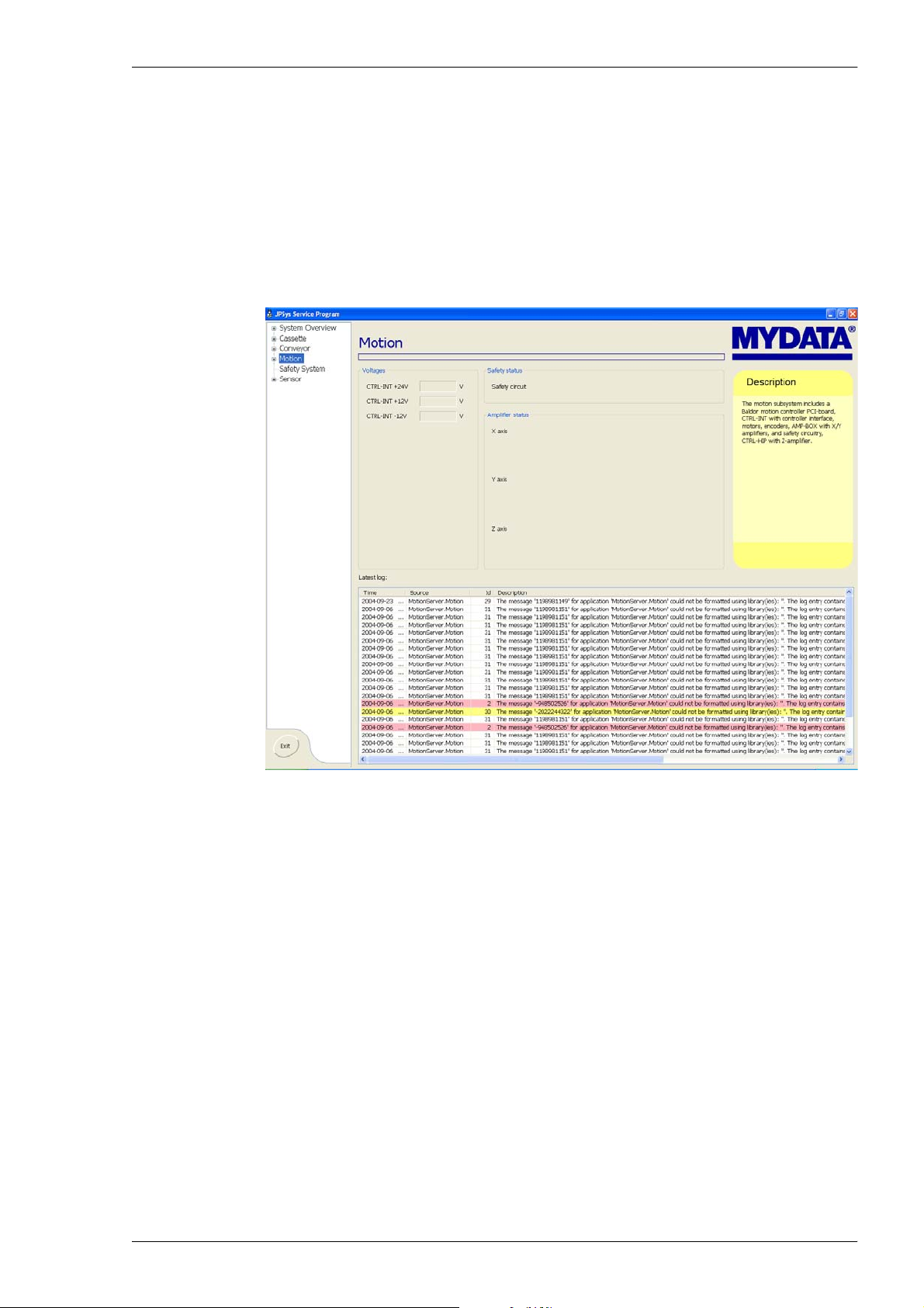
MYDATA MY500 JetPrinter Adjustments
Screen Examples
The system is self-instructing. The initial screens are overview screens with a
brief description, and information, of the system. The following screens are
used to test and calibrate system and hardware. In the hardware window
manual adjustments can be made. The operations are described directly in the
interface.
Please see the figures below for screen examples for testing and calibrating the
movement system.
Figure 4-3. The movement sys tem overview screen.
P-030-0014-EN – Service Manual Rev. 0003 2008-06 4 - 3
Page 80
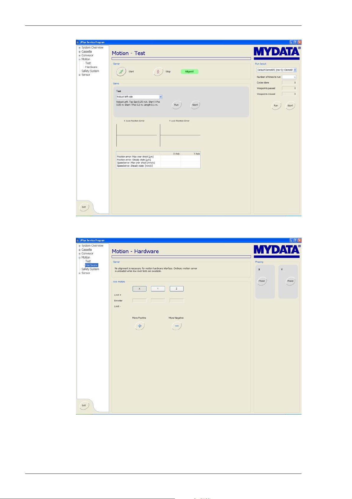
Adjustments MY500 JetPrinter MYDATA
Figure 4-4. The movement system test screen.
Figure 4-5. The movement system hardware screen.
4 - 4 Rev. 0003 2008-06 P-030-0014-EN – Service Manual
Page 81

MYDATA MY500 JetPrinter Routine Maintenance
5. Routine Maintenance
This chapter informs about preventive maintenance for the MY500 JetPrinter.
The described maintenance should be performed at stated intervals. The
warranty on the machine and parts applies only if these instructions are
followed.
WARNING! Before commencing any maintenance, press an emergency stop
button down or turn the power off.
The following maintenance work is described:
• Daily Maintenance.
• Weekly Maintenance.
• Monthly Maintenance.
• Yearly Maintenance.
• Changing Calibration Paper.
• Changing Waste Container.
• Changing Cassette Ejector.
• Lubricating X wagon Rail – 720 Operating Hours.
• Testing the Safety System.
P-030-0014-EN – Service Manual Rev. 0003 2008-06 5 - 1
Page 82

Routine Maintenance MY500 JetPrinter MYDATA
Maintenance intervals
The intervals for daily and weekly maintenance are fixed. All other
maintenance intervals are dependent on the usage of the machine.
CAUTION! The maintenance intervals apply to a clean environment and an
indoor temperature of maximum 25°C. If operated in a dusty environment, or
higher temperature, it is strongly recommended to perform cleaning and
lubrication after half the stated time intervals.
Cleaning optics
– If the optical surface is very dusty or dirty, remove the dust and dirt
using a spray can with clean air intended for optics. Other air may
contain particles and grease from air pumps and valves which may be
harmful to the optics.
– Clean optics by folding a clean lint-free cloth to the width of the
optics. Apply a small amount of isopropyl alcohol, and gently pass the
cloth over the surface. Ensure there is no film left on the surface after
the use of alcohol. An alternative is to use pre-moistened cleaning
towlettes, especially developed for cleaning of optics.
– Do not use abrasives or cleaning solutions!
Lubricants
Unless otherwise stated, use Shell Tellus oil and OKS 270 grease. Oil and
grease should be applied just to give just a thin film.
Information about Material Safety are found in the Safety chapter.
Spare parts
Part numbers for spare parts are found in the Spare Parts Catalog.
5 - 2 Rev. 0003 2008-06 P-030-0014-EN – Service Manual
Page 83
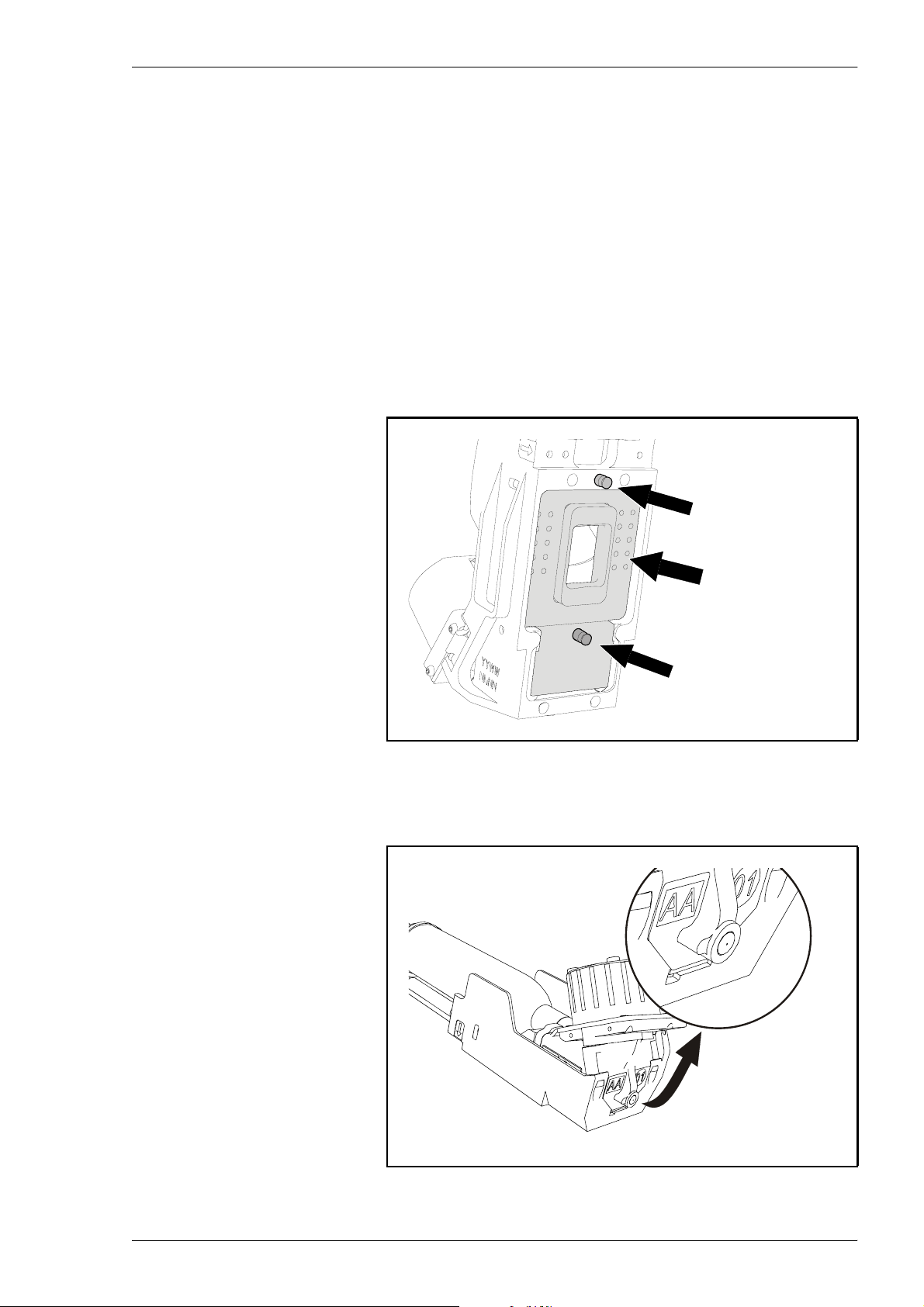
MYDATA MY500 JetPrinter Routine Maintenance
Daily Maintenance
Equipment
– Lint-free cotton wool buds.
– Lint-free cloths.
Cassette
– Check the guide pins on the holder for wear or damage. If the guide
pins are damaged, replace the holder.
– Wipe off any solder paste or dirt from the holder´s backside with a
lint-free cloth.
Guide pin
Holder backside
Guide pin
Figure 5-1. Guide pins and backside of Cassette holder.
– Wipe off solder paste from the nozzle uing a lint-free cloth and attach
protective tape before placing it in a cold storage, see Figure 5-2.
Figure 5-2. Solder paste nozzle.
P-030-0014-EN – Service Manual Rev. 0003 2008-06 5 - 3
Page 84
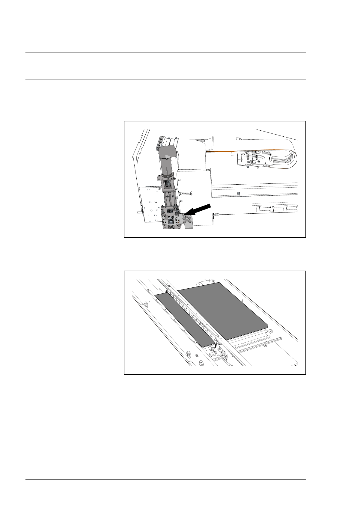
Routine Maintenance MY500 JetPrinter MYDATA
Machine
WARNING! Before commencing, press an emergency stop button down.
– Inspect the Cassette interface. Wipe off any solder paste using a lint-
free cloth. Be careful with the connector surfaces.
Cassette
interface
Figure 5-3. Cassette interface.
– Wipe off any solder paste from the conveyor table.
Figure 5-4. Conveyor table.
– Wipe off any solder paste and glue that may have spilled onto the
machine. This is especially important for glue, which may be harmfull
to machine parts.
5 - 4 Rev. 0003 2008-06 P-030-0014-EN – Service Manual
Page 85
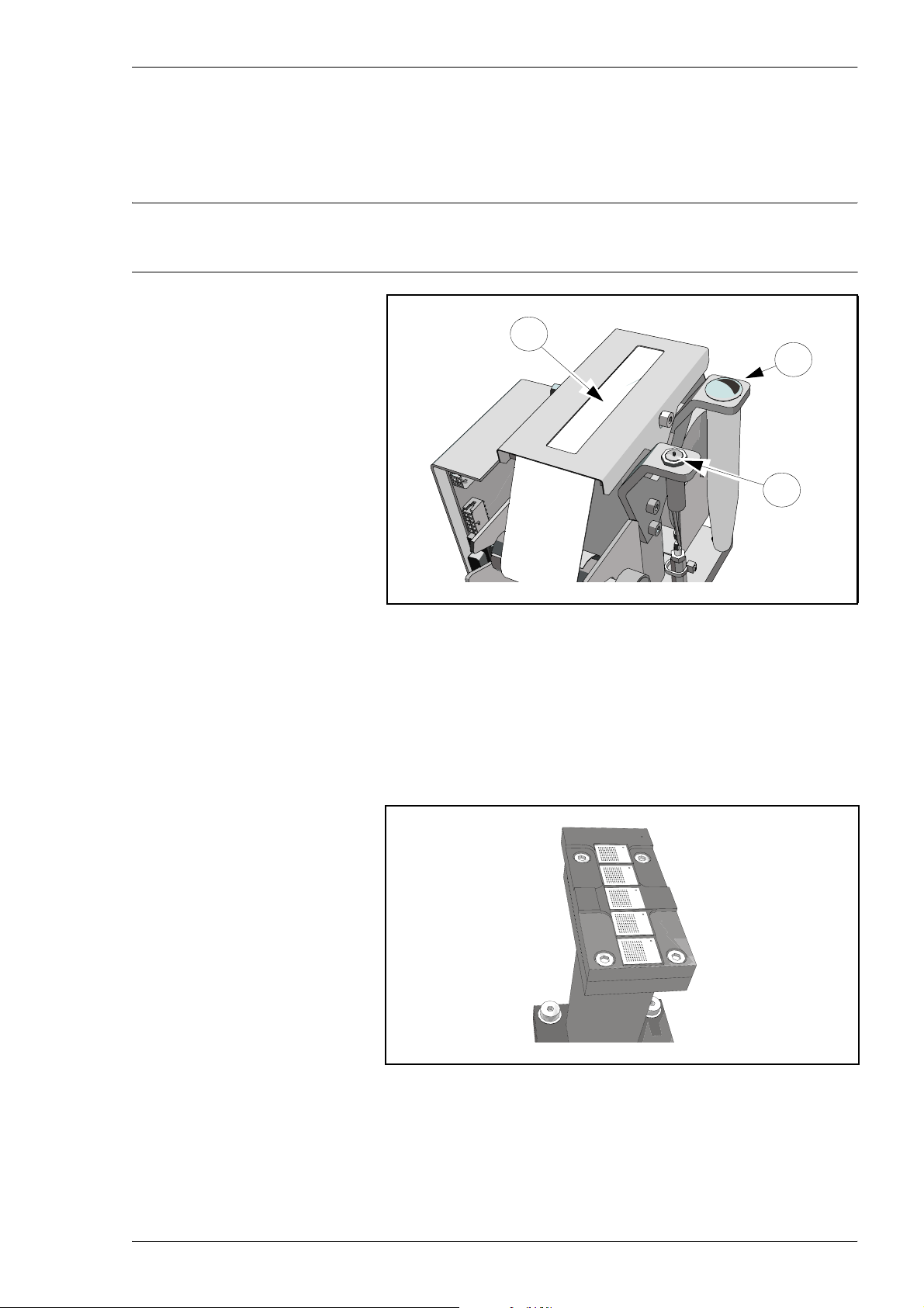
MYDATA MY500 JetPrinter Routine Maintenance
Calibration Units
– Check if the cassette height calibration sensor (’A’ in Figure 2-5) is
clean and can be moved down freely. If not clean, wipe it carefully
using a lint-free cloth.
Do not use any alcohol on the calibration point!
C
B
A
Figure 5-5. Calibration unit.
– Check if the waste container (B) is getting full. Replace the waste
container if necessary, see the MY500 JetPrinter, Service Manual.
– Check the quantity of paper (C). Reload if there is a red line on the
paper´s side, see the MY500 JetPrinter, Service Manual.
– Wipe away any solder paste or dirt from the unit using a lint-free
cloth. Be careful not to leave any dirt on the white calibration spots.
Figure 5-6. Camera calibration unit.
P-030-0014-EN – Service Manual Rev. 0003 2008-06 5 - 5
Page 86
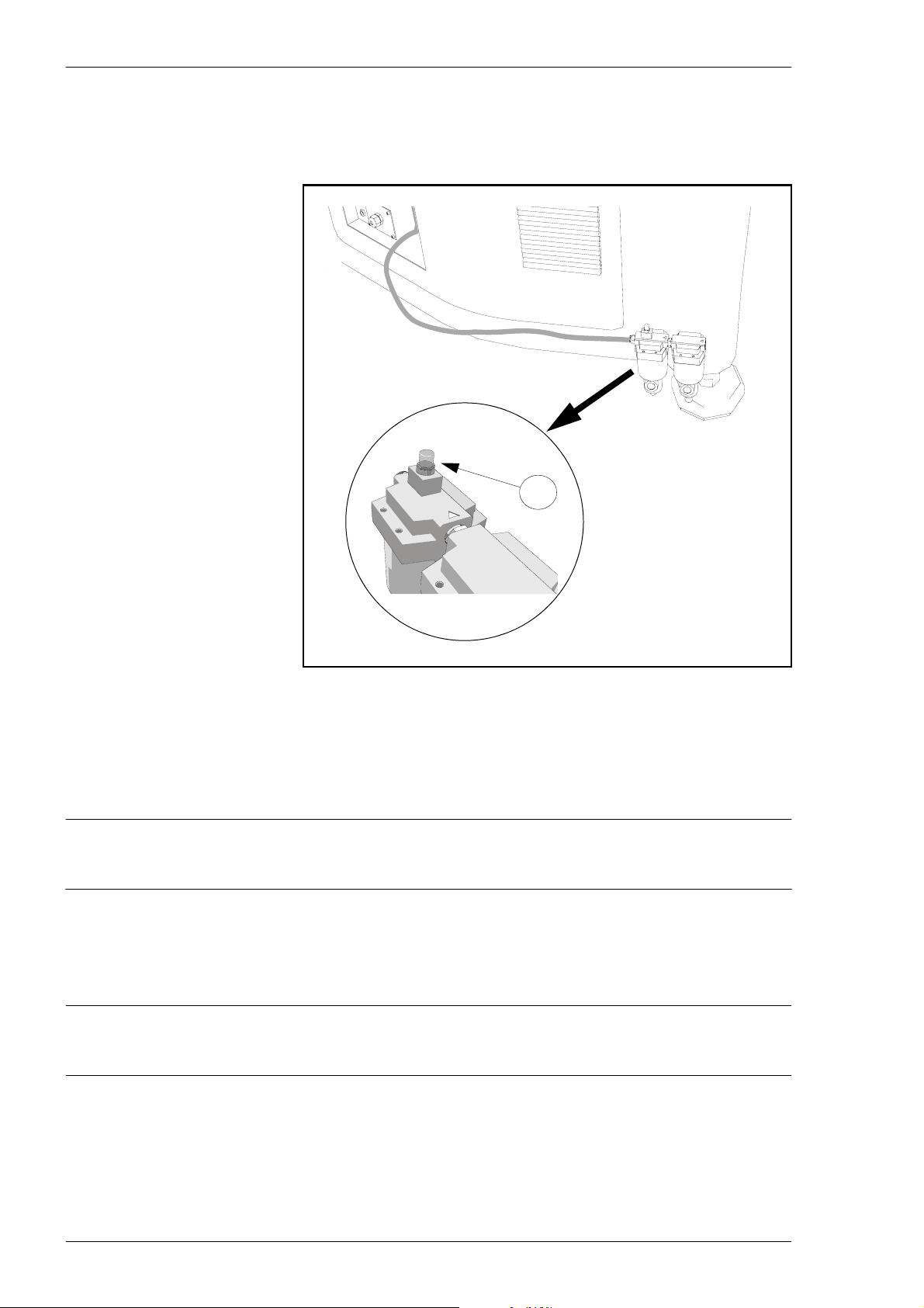
Routine Maintenance MY500 JetPrinter MYDATA
Filters
The air filter indicator (’A’ in the figure) is located on one of the two air
filters.
A
Figure 5-7. Air filter indicator.
If the machine is equipped with an optional Refrigerated Air Dryer unit,
the air filters are located on that unit.
– Replace both the filters if the filter indicator has turned red (refer to
the filter manual).
These filters must be exchanged every two years.
Optional Refrigerated Air Dryer
– Make sure the auto drain operates properly (refer to the Refrigerated
Air Dryer manual).
CAUTION! A bad quality of compressed air can cause auto drain malfunction.
5 - 6 Rev. 0003 2008-06 P-030-0014-EN – Service Manual
Page 87
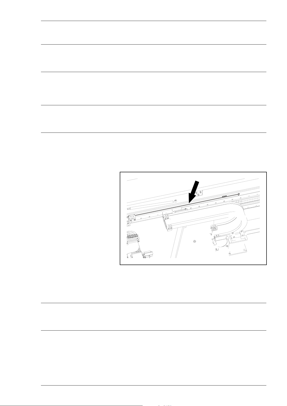
MYDATA MY500 JetPrinter Routine Maintenance
Weekly Maintenance
This preventive maintenance shall only be carried out by authorized service
Equipment
Machine
engineers.
– Lint-free cloths.
WARNING! Before commencing, switch the power off, and lock out and tag
the main switch.
– Wipe off the Y linear scale using a dry lint-free cloth. Be careful not
to scratch or damage the surface.
Y linear scale
Figure 5-8. Y linear scale.
To be able to reach the rear part of the linear scale, you must remove
the rear top hood. This is done by unscrewing the hood’s four mount
screws.
WARNING! Always re-attach the rear hood, using four screws, before
P-030-0014-EN – Service Manual Rev. 0003 2008-06 5 - 7
switching the power on.
Page 88
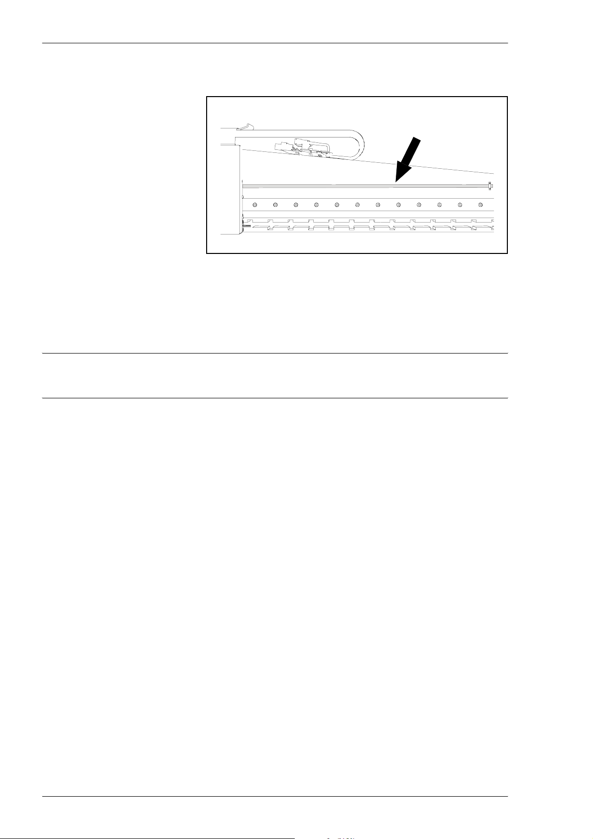
Routine Maintenance MY500 JetPrinter MYDATA
– Wipe off the X linear scale using a dry lint-free cloth. Be careful not
to scratch or damage the surface.
X linear scale
Figure 5-9. X linear scale.
Others
– Wipe off the screen if needed. Use a soft cloth and dampen the cloth
slightly with clean water. Do not use abrasives or cleaning solutions.
Do not use abrasives or cleaning solutions!
– Warning signs on the machine must be clean and readable. If needed,
clean or replace the signs (refer to the MY500 JetPrinter, Operator’s
Manual).
5 - 8 Rev. 0003 2008-06 P-030-0014-EN – Service Manual
Page 89

MYDATA MY500 JetPrinter Routine Maintenance
Monthly Maintenance
This preventive maintenance shall only be carried out by authorized service
Equipment
Machine
engineers.
– Lint-free cloths.
– Vacuum cleaner or blow nozzle.
– Remove dust from the ventilation areas on the top back hood.
Use a vacuum cleaner or an air blow nozzle.
Optional Refrigerated Air Dryer
– Remove dust from the ventilation area on the optional Refrigerated
Air dryer. Use a vacuum cleaner or an air blow nozzle.
– Check valves for scratches, gouges, abrasion, and corrosion.
– Check tubes and valves for air leakage.
– Check tubes for twisting, flattening, or distortion.
– Check tubes for hardening, deterioration, or softness.
Replace components as necessary. Refer to the Refrigerated Air Dryer
manual.
P-030-0014-EN – Service Manual Rev. 0003 2008-06 5 - 9
Page 90

Routine Maintenance MY500 JetPrinter MYDATA
Yearly Maintenance
This preventive maintenance shall only be carried out by authorized
MYDATA service engineers. There is a specific instruction for the yearly
maintenance that has to be followed.
Please contact your MYDATA Service Department to arrange for a visit by a
MYDATA field service engineer.
This service will affect for example:
– Calibr ation of optics.
– Y beam calibration and adjustments.
–The Xsystem.
– The internal conveyor system.
5 - 10 Rev. 0003 2008-06 P-030-0014-EN – Service Manual
Page 91
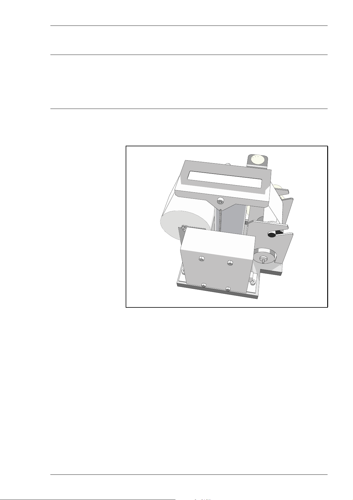
MYDATA MY500 JetPrinter Routine Maintenance
Changing Calibration Paper
This preventive maintenance shall only be carried out by authorized service
engineers.
WARNING! Before commencing, switch the power off, and lock out and tag
the main switch.
The solder paste cassette is calibrated every time you change it or initiate the
hardware. Calibration is done by shooting a test pattern onto a roll of paper on
the cassette calibration unit.
Figure 5-10. Cassette calibration unit.
If necessary, the paper roll is replaced as follows:
P-030-0014-EN – Service Manual Rev. 0003 2008-06 5 - 11
Page 92
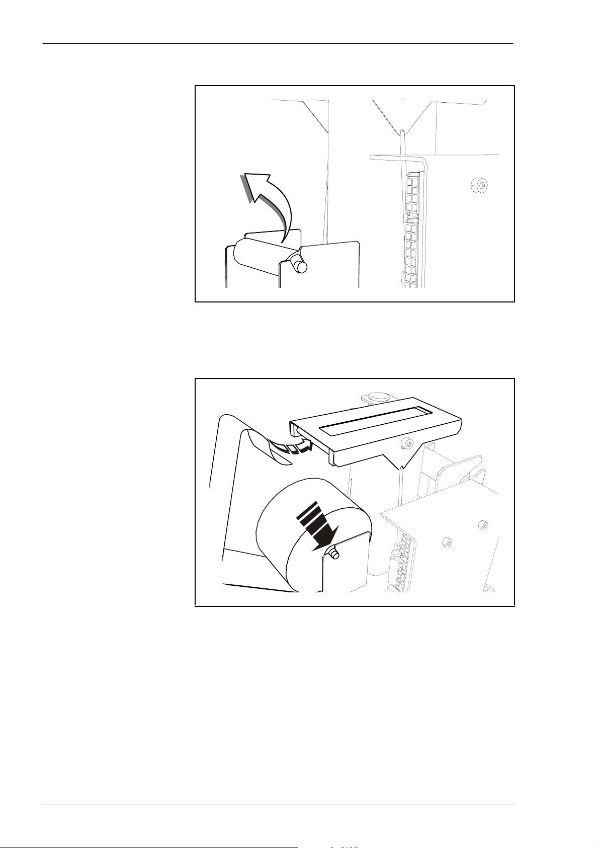
Routine Maintenance MY500 JetPrinter MYDATA
1. Remove the empty roll and spent paper.
2. Push a new paper roll onto the first shaft and place it in the holder. Feed
the paper into the slot in the paper guide and pull it through.
Be carefull not to damage the metal sheet when you pull the paper
through the paper guide.
5 - 12 Rev. 0003 2008-06 P-030-0014-EN – Service Manual
Page 93
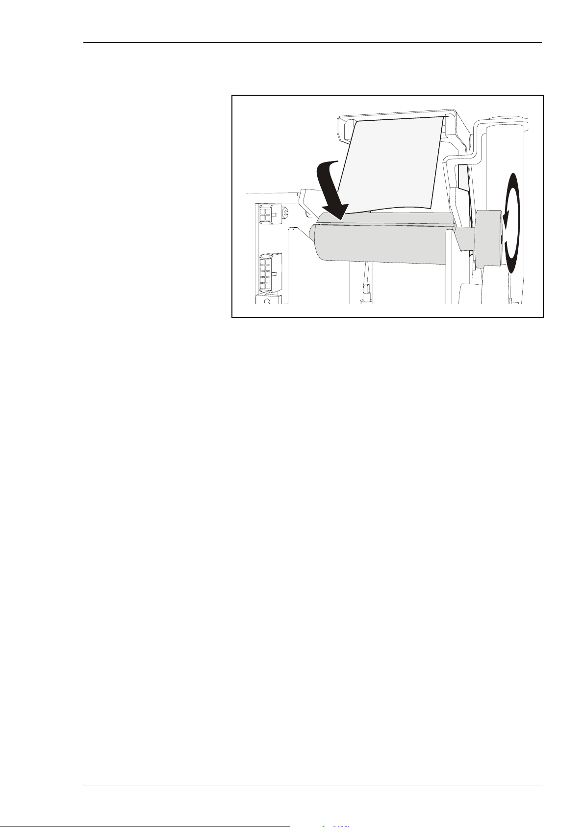
MYDATA MY500 JetPrinter Routine Maintenance
3. On the other side of the paper guide, push the paper into the feeder shaft
slot. Roll the wheel to secure the paper to the wheel.
P-030-0014-EN – Service Manual Rev. 0003 2008-06 5 - 13
Page 94
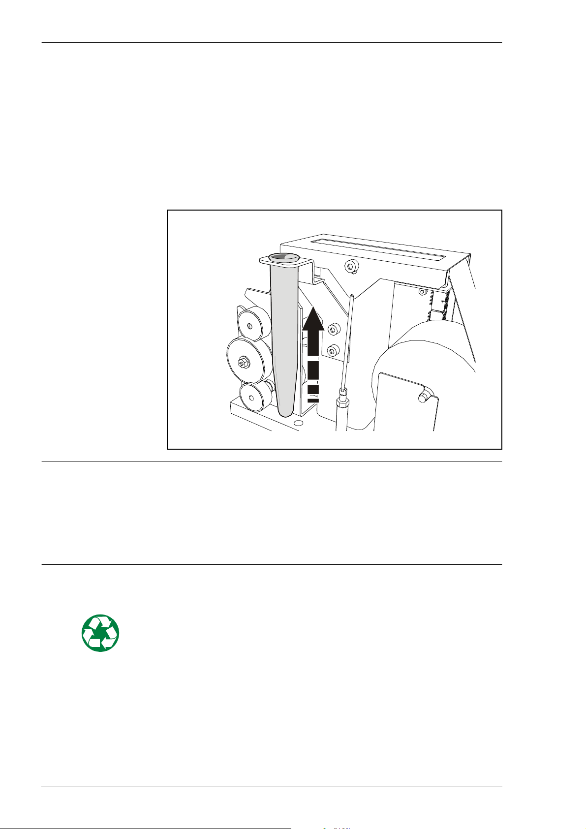
Routine Maintenance MY500 JetPrinter MYDATA
Changing Waste Container
When you use the Purge button, the cassette will do ’dummy’ shots into a
waste container on the cassette calibration unit.
Check the container regularly. Change if the container is 2/3 full, otherwise
solder paste may splash outside of the container when purging.
To change the container
Lift the container straight up and insert a new one.
Waste Disposal
WARNING! Solder paste, during handling or use, may be ha zardous to health
or the environment. Read the Material Safety Data Sheet and warning label
before using. Always remember that care should be taken to avoid the
ingestion of solder paste. As solder paste often contains lead and/or other
toxic materials, gloves and gowns should be worn while using solder paste,
and hands should be washed afterwards.
Solder paste and any material with remnants of solder paste in, or on, them
must be treated as hazardous waste.
5 - 14 Rev. 0003 2008-06 P-030-0014-EN – Service Manual
Page 95
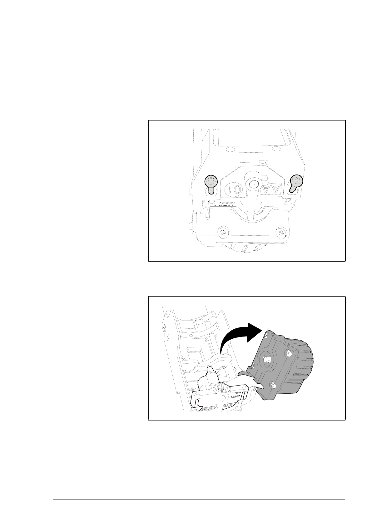
MYDATA MY500 JetPrinter Routine Maintenance
Changing Cassette Ejector
An ejector, at the bottom of the holder, carries the piezo unit and a nozzle. The
piezo unit generates the force needed to eject the solder paste through the
nozzle.
This ejector is good for 30 solder paste cartridges. After that it must be
changed. To change the ejector, do as follows:
1. Loosen the two torx screws at the bottom of the holder.
Figure 5-11. Loosening two screws.
2. Swing the motor over towards the right.
Figure 5-12. Swing the motor to the right.
P-030-0014-EN – Service Manual Rev. 0003 2008-06 5 - 15
Page 96
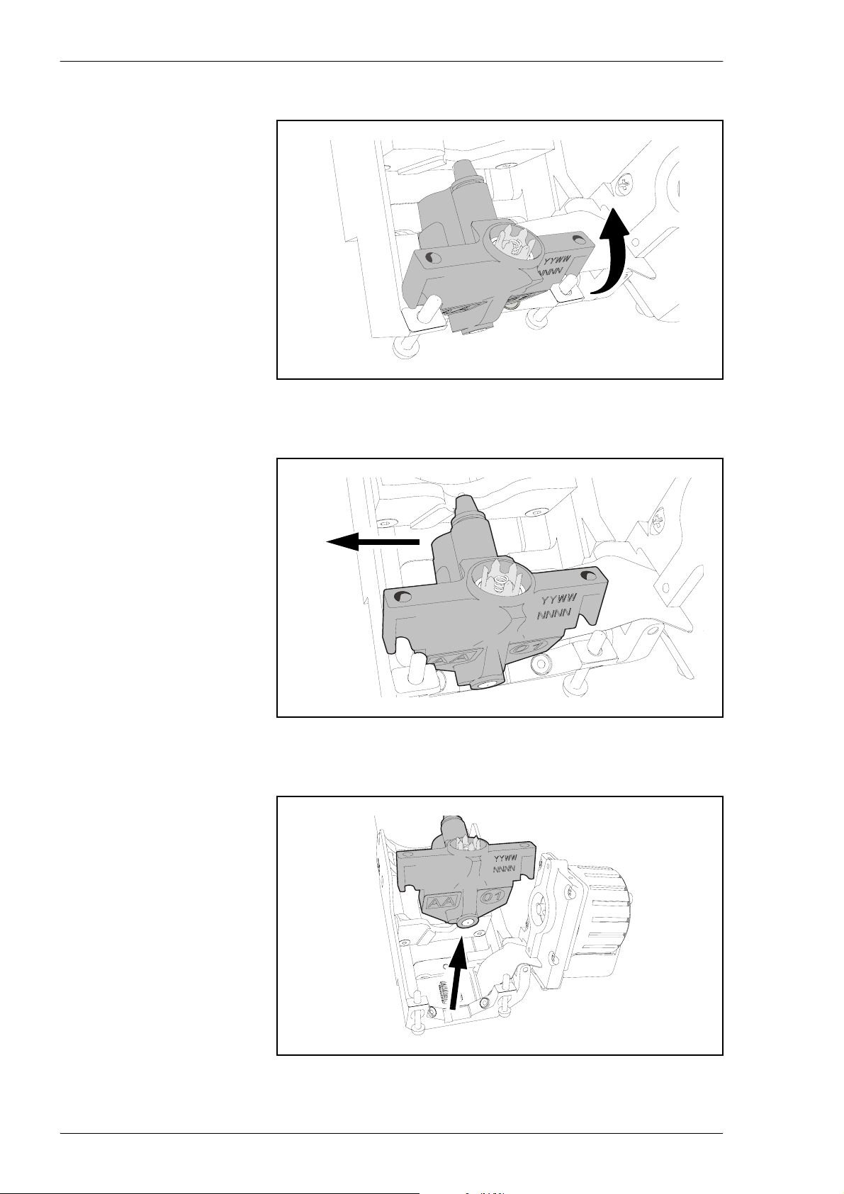
Routine Maintenance MY500 JetPrinter MYDATA
3. Tilt the ejector up-wards slightly.
Figure 5-13. Tilting the ejector.
4. Pull the ejector out from the holder to the left.
Figure 5-14. Pulling the ejector out.
5. Lift the ejector away from the holder.
Figure 5-15. Lifting the ejector.
5 - 16 Rev. 0003 2008-06 P-030-0014-EN – Service Manual
Page 97
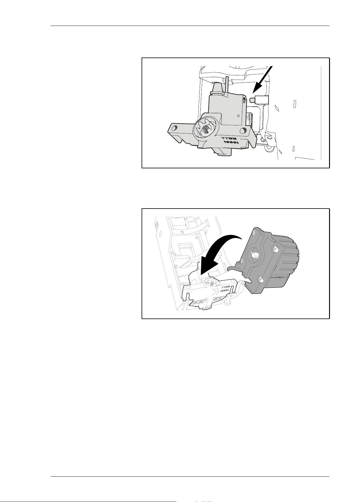
MYDATA MY500 JetPrinter Routine Maintenance
6. Remove the two yellow, protective plastic caps. Slip a the ejector into
the holder from the left. Push it onto the pin, see Figure 5-16.
Figure 5-16. Slipping the ejector into the holder.
7. Push down and swing the motor back in place. Re-tighten the two torx-
screws which you loosened in step 1, see Figure 5-11.
Figure 5-17. Pushing down the motor.
P-030-0014-EN – Service Manual Rev. 0003 2008-06 5 - 17
Page 98

Routine Maintenance MY500 JetPrinter MYDATA
Be careful not to loose the spring, highlighted in Figure 5-18, when you take
a new ejector out of its packing.
Figure 5-18. Ejector spring.
In a new ejector there is a conditioner that must be removed before it can used
in production. After having changed the ejector, and inserted a cartridge,
always do an Extended Purge. Hereby the conditioner will be replaced with
fresh solder paste.
5 - 18 Rev. 0003 2008-06 P-030-0014-EN – Service Manual
Page 99
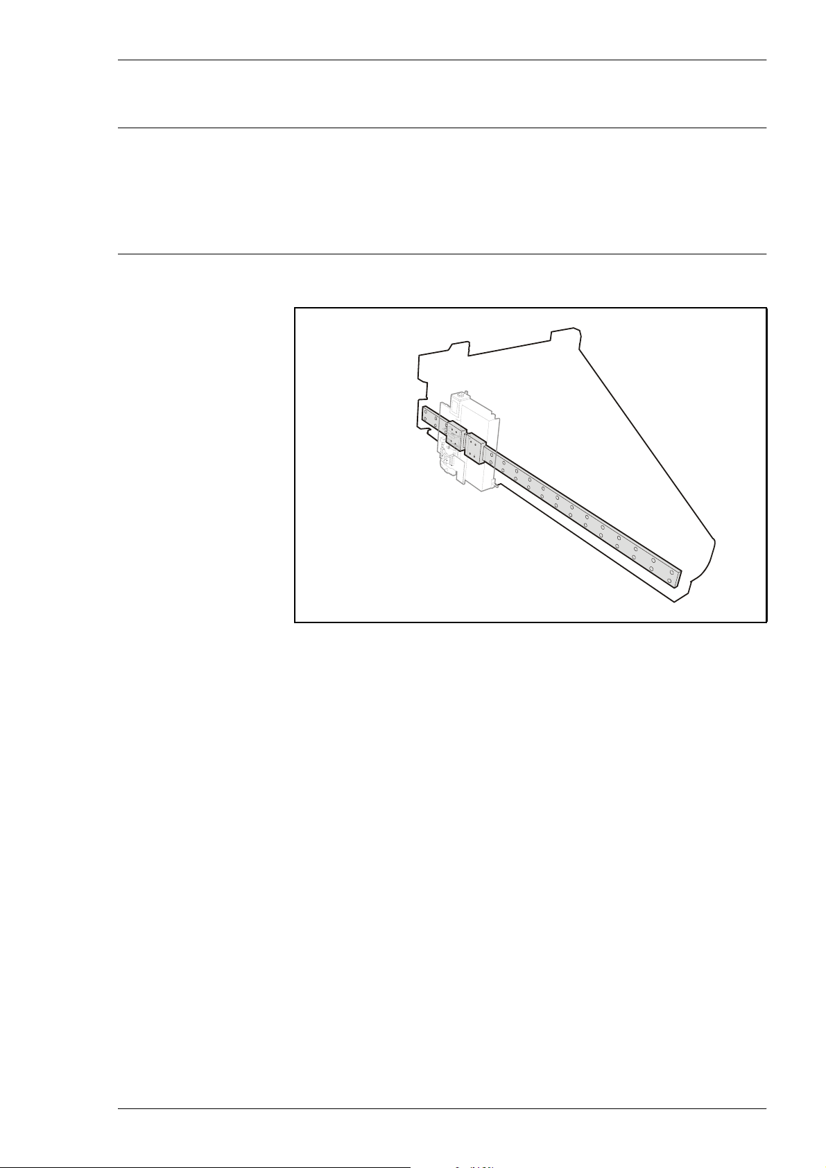
MYDATA MY500 JetPrinter Routine Maintenance
Lubricating X wagon Rail – 720 Operating Hours
This preventive maintenance shall only be carried out by authorized service
engineers.
WARNING! Before commencing, switch the power off, and lock out and tag
the main switch.
Every 720 hours the X-wagon rail, and bearings need to be lubricated .
Figure 5-19. X-wagon rail and bearings.
Equipment
– Grease gun from the spare parts kit.
– AFA lubricant, MYDATA part number K-035-0095.
Performing
1. Turn off the power, and lock and tag the main switch.
2. Open the machine front hood.
3. Apply a thin layer of grease on the rail, using the grease gun. Wipe away
any excess grease with a lint-free cloth.
4. Move the X wagon along the rail a couple of times, to distribute the
grease evenly.
5. Close the front hood.
6. Remove the lock ant tag, and restart the machine.
P-030-0014-EN – Service Manual Rev. 0003 2008-06 5 - 19
Page 100
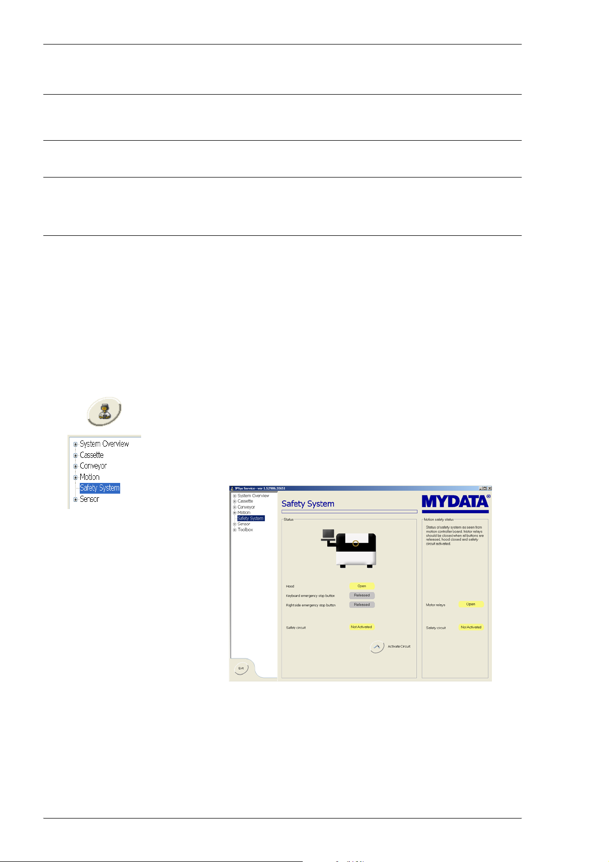
Routine Maintenance MY500 JetPrinter MYDATA
Testing the Safety System
This maintenance shall only be carried out by authorized service engineers.
The safety system should be tested at regular intervals.
WARNING! Ensure no hands, fingers, or other objects are entered within the
shielded area before the machine has stopped.
1. With the machine running a job, press the emergency stop button on the
MMI. Check that the machine has stopped.
2. Release the stop button and do the same test with the emergency stop
button on the machine front.
3. Release the stop button and do the same test by opening the front hood.
Testing the Safety Circuits
With the Service system you can test the safety system circuits.
1. Go to the Exit tab and select Start Service Program to enter the Service
system.
2. Select Safety System in the file list to go to the safety system window.
3. Open the front hood, check that you get an indication that it is open, see
the figure below.
Figure 5-20. System showing hood is open.
4. Close the hood and check that the system indicates this.
5. Do the same test with all emergency stop buttons.
The safety system circuit is described in the block scehmatics.
5 - 20 Rev. 0003 2008-06 P-030-0014-EN – Service Manual
 Loading...