

Page 1
November 2013
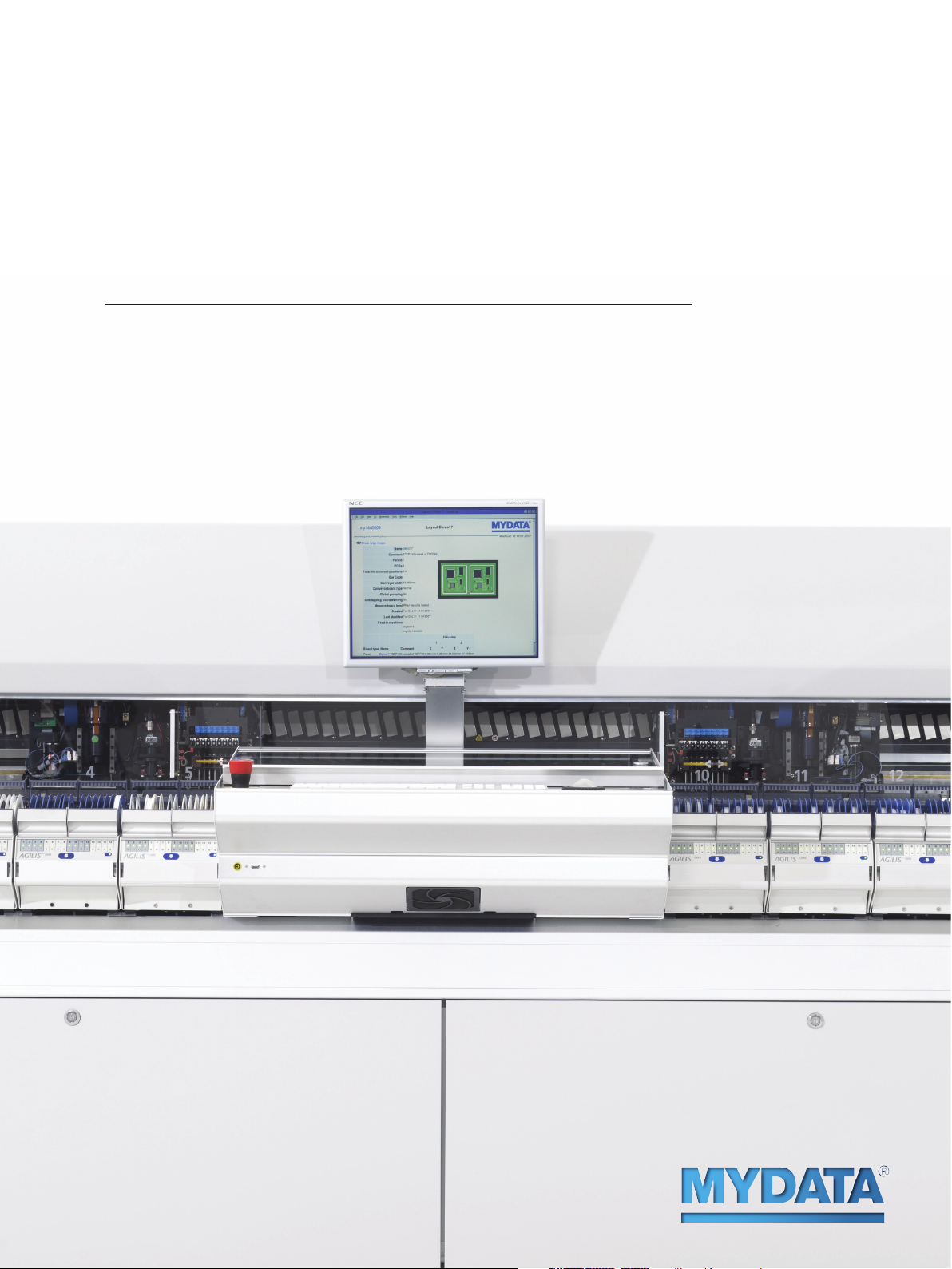
MY200 Series P&P
Specification
™
MY200SX
Page 2
MY200-SERIES P&P SPECIFICATION – MY200SX
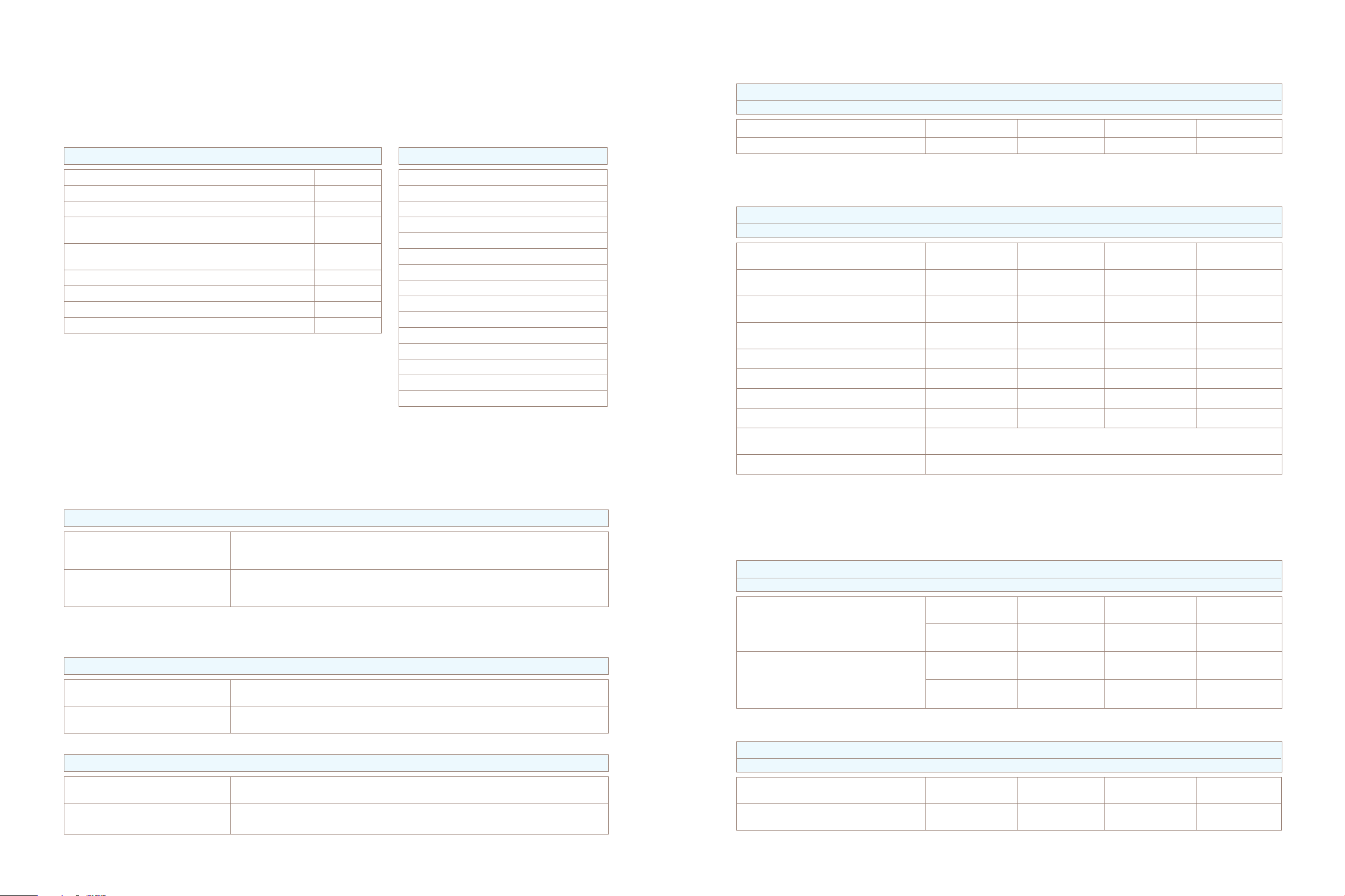
FEEDER CAPACITY
FEEDER CAPACITY 8 MM TAPE
T3 T4 T5 T6
PLACEMENT SPEED AND ACCURACY
PLACEMENT SPEED AND ACCURACY – MY200SX 10/14
Rated Speed
IPC 9850 Chip Net Throughput
IPC 9850 Chip Tact Time
IPC 9850 Chip Repeatability 3s (X, Y, Theta)
IPC 9850 Chip Accuracy @ Cpk = 1.33 (X, Y, Theta)
IPC 9850 Fine Pitch Net Throughput
IPC 9850 Fine Pitch Tact Time
IPC 9850 Fine Pitch Repeatability 3s (X, Y, Theta)
IPC 9850 Fine Pitch Accuracy @ Cpk = 1.33 (X, Y, Theta)
The above specification achieved with a machine configuration including high precision mounthead (Midas),
high speed mounthead (HYDRA Z8), line scan vision system (LVS) and inline conveyor T3.
The IPC 9850 net throughput and accuracy numbers are obtained simultaneously, with the same machine settings.
The rated Speed value is obtained under conditions optimized for speed.
1) Depending on component and application.
2) According to IPC 9850. Net Throughput = (no of parts x 3600) / (board build time + board transfer time).
3) According to IPC 9850 0402C verification panel.
4) According to IPC 9850 QFP64/QFP100 verification panel.
5) According to IPC 9850 Cpk 1.33 = 4s + offset.
6) Small chip settings, recommended for 0201 (0.6 x 0.3 mm) and below.
(1)
(2,3)
(3)
(3)
24 000 CPH
20 000 CPH
0.163 s
30 µm, 1.8°
45 µm, 1.8°
(5)
50 µm, 2.6°
75 µm, 2.6°
(2,4)
(4)
(4)
(4,5)
3 200 CPH
0.958 s
21 µm, 0.05°
35 µm, 0.09°
SYSTEM FEATURES
SYSTEM FEATURES MY200SX
On-the-fly mount order optimization
Vision autoteach with snap-to-grid
Automatic illumination settings
(6)
(6)
Intelligent feeder concept – Agilis
On-the-fly feeder loading
Automatic feeder and component recognition
Dynamic feeder positions
Automatic board stretch compensation
Automatic conveyor width adjustment
Intelligent surface impact control
Tool collision avoidance
Multi-user, multi-tasking system software
Open software interfaces for factory integration
SQL database engine
Programmable light settings fiducial camera
MY200SX-10 112 96 - -
MY200SX-14 176 160 144 128
BOARD HANDLING
INLINE CONVEYOR
T3 T4 T5
Maximum Board Size 443 x 508 mm
(17.4” x 20”)
Maximum Board Size with ML adaptor
(2)
419 x 443 mm
(16.5” x 17.4”)
Minimum Board Size
(3)
70 x 50 mm
(2.7” x 2”)
Board Thickness Range 0.4 - 6.0 mm
(0.016” - 0.24”)
Board Edge Clearance Top and Bottom 3.2 mm (0.13”) 3.2 mm (0.13") 3.2 mm (0.13") 3.2 mm (0.13")
Top Side Clearance (max)
(4)
15 mm (0.59”) 15 mm (0.59") 15 mm (0.59") 15 mm (0.59")
Bottom Side Clearance (max) 32 mm (1.25”) 32 mm (1.25") 32 mm (1.25") 32 mm (1.25")
Maximum Board Weight 5 kg (11 lbs) 8 kg (17 lbs) 15 kg (33 lbs) 15 kg (33 lbs)
Board Transfer Height Conforms to SMEMA standard for board transfer height. Height adjustable from 880 to
975 mm (34.6” to 38.4”).
Operation Mode Inline, manual, inline odd-board, left-to-right / right-to-left
575 x 508 mm
(22.6" x 20")
554 x 443 mm
(21.8" x 17.4")
70 x 50 mm
(2.7" x 2")
0.4 - 6.0 mm
(0.016" - 0.24")
(1)
T6
736 x 609 mm
(29" x 24")
725 x 556 mm
(28" x 22")
70 x 50 mm
(2.7" x 2")
0.8 - 12.5 mm
(0.03" - 0.5")
(1)
914 x 609 mm
(36" x 24")
905 x 556 mm
(35.5" x 22")
70 x 50 mm
(2.7" x 2")
0.8 - 12.5 mm
(0.03" - 0.5")
COMPONENT RANGE
HIGH PRECISION MOUNTHEAD – MIDAS
Component Range Chip (from 01005), SOIC, PLCC, TSOP, QFP, BGA, flip chip, odd-shape,
Component Specification Min: 0.4 x 0.2 mm (0.016” x 0.008”) (01005)
1) Customized larger component capabilty available: 76 x 66 x 15 mm (2.9” x 2.6” x 0.59”) or 151 x 26 x 15 mm (5.9” x 1.0” x 0.59”). Customized tall component capability 22 mm (0.86”) available.
Contact MYDATA sales for detailed customization information.
2) Depending on mounthead, mount tool, package, and production altitude.
HIGH SPEED MOUNTHEAD – HYDRA Z8
Component Range Chip (from 0201), SO28, SOT223, SOJ20, PLCC32, MELF, SOD, TSOP
Component Specification Min: 0.6 x 0.3 mm (0.02 x 0.01”) (0201)
ELECTRICAL VERIFIER (OPTIONAL)
Component Range Resistor, Capacitor, Unipolar Capacitor, Diode (forward voltage, reverse current),
Verification Time On-the-fly
surface-mount connectors, through-hole components, CSP, CCGA, DPAK,
Alcap, Tantalum.
Max: 56 x 56 x 15 mm (2.20” x 2.20” x 0.59”)
Max: component weight: 140 g
(2)
(1)
Max: 18.6 x 18.6 x 5.6 mm (0.73 x 0.73 x 0.22”) (PLCC44)
Zener diode (voltage drop), Transistor (current gain)
1) Available for MY200SX-14.
2) Optional. Suitable for irregular sized and odd shaped boards.
3) Recommended board train specification: 90 x 50 mm (3.5” x 2”) board size, 1.6 mm (0.06”) thickness.
4) Customized tall component capability 22 mm (0.86”)
VISION CAPABILITY
DUAL VISION SYSTEM (OPTIONAL)
componenT Type camera max acTive field of view min piTch min lead widTh
Leaded Components SVC
Bumped Components SVC
1) Standard vision camera in dual vision system (DVS).
2) High resolution camera in dual vision system (DVS).
LINESCAN VISION SYSTEM
componenT Type camera max acTive field of view min piTch min lead widTh
Leaded Components LVC
Bumped Components LVC
1) Line scan vision camera.
(1)
56 x 52 mm
(2)
HRC
(1)
56 x 52 mm
(2)
HRC
(1)
56 x 56 mm
(1)
56 x 56 mm
(2.20” x 2.04”)
15 x 15 mm
(0.59” x 0.59”)
(2.20” x 2.04”)
15 x 15 mm
(0.59” x 0.59”)
(2.2” x 2.2”)
(2.2” x 2.2”)
0.40 mm (16 mil) 0.20 mm (8 mil)
0.10 mm (4 mil) 0.05 mm (2 mil)
0.50 mm (20 mil) 0.25 mm (10 mil)
0.16 mm (6.3 mil) 0.08 mm (3.1 mil)
0.20 mm (8 mil) 0.10 mm (4 mil)
0.30 mm (12 mil) 0.15 mm (6 mil)
Page 3
SOFTWARE
MISCELLANEOUS
SOFTWARE MODULES (OPTIONAL)
Shared Databases
Line Mode
PCB ID (2D barcode)
Electrical Measurement Log
Pre-Pick Inspection
Barcode Software
OFFLINE SOFTWARE TOOLS (OPTIONAL)
Data Preparation – MYCam
Machine Programming – MYCenter
Optimization and Scheduling – MYPlan
Inventory Management and Kitting – MYCenter
Traceability – MYTrace
Line Automation – FlowLine
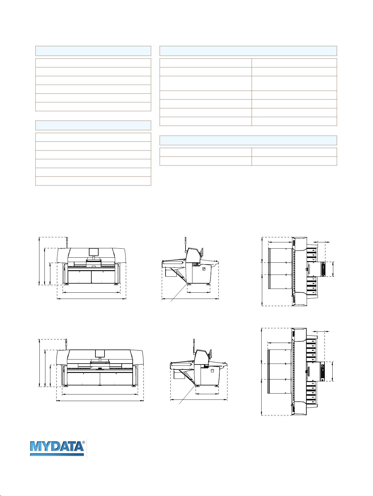
DIMENSIONS
in mm.
MY200SX-10 T3
INSTALLATION REQUIREMENTS
Power Requirements Three phase AC 6.6 kVA (3 x 2.2 kVA)
Power Consumption 1.5 kW (average)
Voltages 3 x 200, 210, 220, 230, 240, 250
Air Supply No air required
Noise 65 dBA
Air Temperature +18 to +35 °C (65 to 95 °F)
Air Humidity < 95% RH non condensing
MACHINE WEIGHT
(1)
MY200SX-10 1 400 kg (3 100 lbs)
MY200SX-14 1 700 kg (3 700 lbs)
1) Total machine weight excluding magazines.
+-10%, Y or Delta
1869
1446
864
MY200SX-14 T4
1869
1446
864
2250
2690
2970
3410
2229
POWER CONNECTOR
POWER CONNECTOR
899
2229
899
995
475
1220
610
1400 1400
293935
579
293
935
759
Micronic Mydata AB
PO Box 3141
SE-183 03 Täby
Sweden
www.mydata.com
Specifi cations are subject to change without notice.
MYDATA, MYDATA automation and MY; MY100, MY100DX, MY100SX, MY100LX, MY100e, MY100HXe, MY100DXe, MY100SXe, MY100LXe, MY200, MY200HX, MY200DX, MY200SX, MY200LX, MY500 and MYSynergy; T3, T4, T5 and T6; HYDRA Speedmount, Midas, ISIC; Agilis, Agilis
Linear Magazine (ALM), Agilis Linear Magazine Flex (ALM FLEX), Agilis Stick Magazine (ASM), MYDATA Tray Exchanger (TEX), MYDATA Tape Magazine (TM), MYDATA Tray Wagon Magazine (TWM); MYDATA Dip Unit (DPU); MYDATA Standard Vision System (SVS), MYDATA Dual Vision System
(DVS), MYDATA Linescan Vision System (LVS), MYDATA HYDRA Vision System (HVS); MYDATA Assembly Process Management (APM) including; JPSys, TPSys, MYLabel, MYPlan, MYCenter, MYTrace, MYCam, FlowLine and CAD Conversion are registered trademarks or trademarks of
Micronic Mydata AB. MYDATA is ISO 9001:2008 certifi ed.
Visit: Nytorpsvägen 9, Täby
Tel: +46 8 638 52 00
Fax: +46 8 638 52 90
MYDATA Asia
Tel: +65 6281 7997
Fax: +65 6281 7667
MYDATA Benelux
Tel: +31 402 62 06 67
Fax: +31 402 62 06 68
MYDATA China
Tel: +86 21 3252 3785/86
Fax: +86 21 3252 3780
MYDATA France
Tel: +33 1 41 80 15 80
Fax: +33 1 46 86 77 89
MYDATA Germany
Tel: +49 89 45 24 24 8-0
Fax: +49 89 45 24 24 8-80
MYDATA Japan
Tel: +81 42 354 1320
Fax: +81 42 354 1321
MYDATA UK
Tel: +44 1 202 723 585
Fax: +44 1 202 723 269
MYDATA USA
Tel: +1 978 948 6919
Fax: +1 978 948 6915
MYDATA South Korea
Tel: +82 31 387 5111
Fax: +82 31 388 0087
P-001-0263 rev 0000 / November 2013
 Loading...