

Murata
Manufacturing Co., Ltd.
Cat.No.O05E-5
CHIP COIL
CHIP COIL
This is the PDF file of catalog No.O05E-5. No.O05E5.pdf 00.3.15
This is the PDF file of catalog No.O05E-5. No.O05E5.pdf 00.3.15
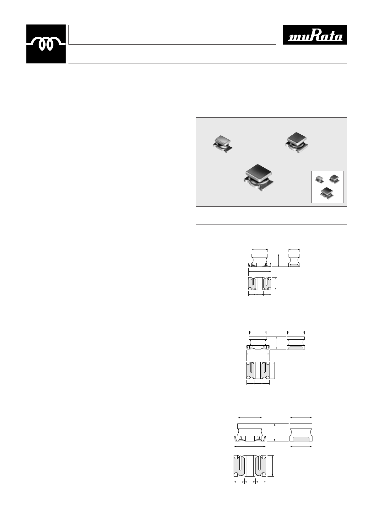
Murata's LQ- series of chip coils consists of compact, highperformance inductors. Their innovative coil and case
structures mean low DC resistance and outstanding
!PRODUCTS GUIDE
high-frequency characteristics. The series is designed for a
variety of applications, facilitating component selection for
individual circuit requirements.
Please refer to the usage conditions;
¡Notice of Chip Coil
.................................................
P.42YP.45
¡Dimensions of Taping
.......................................................
P.46
Please refer to the usage conditions;
¡Design Kit
...............................................................
P.47YP.50
¡Information of Chip Coil
....................................................
P.51
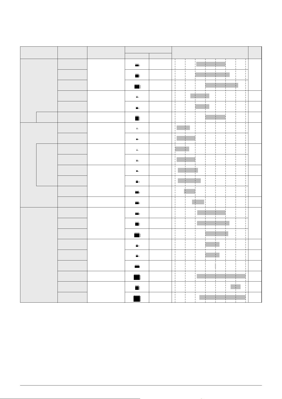
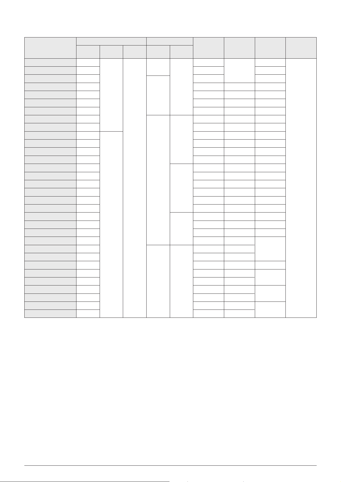
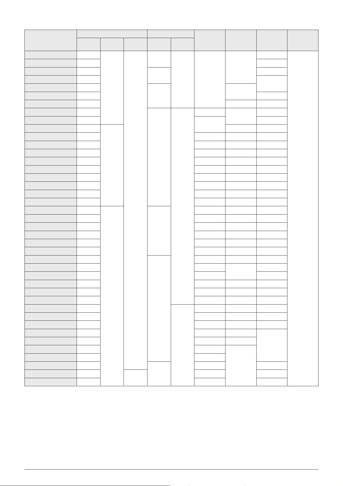
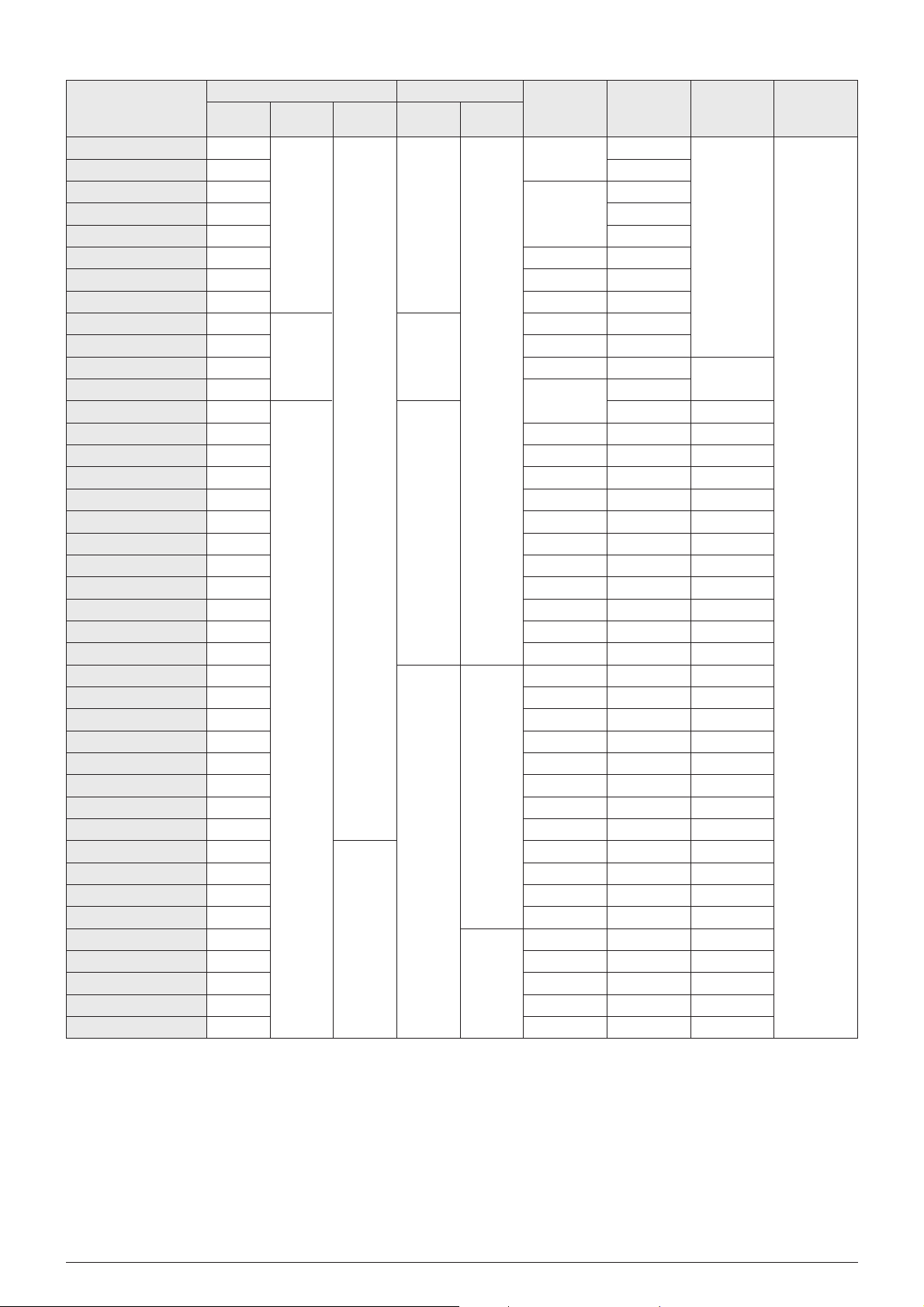
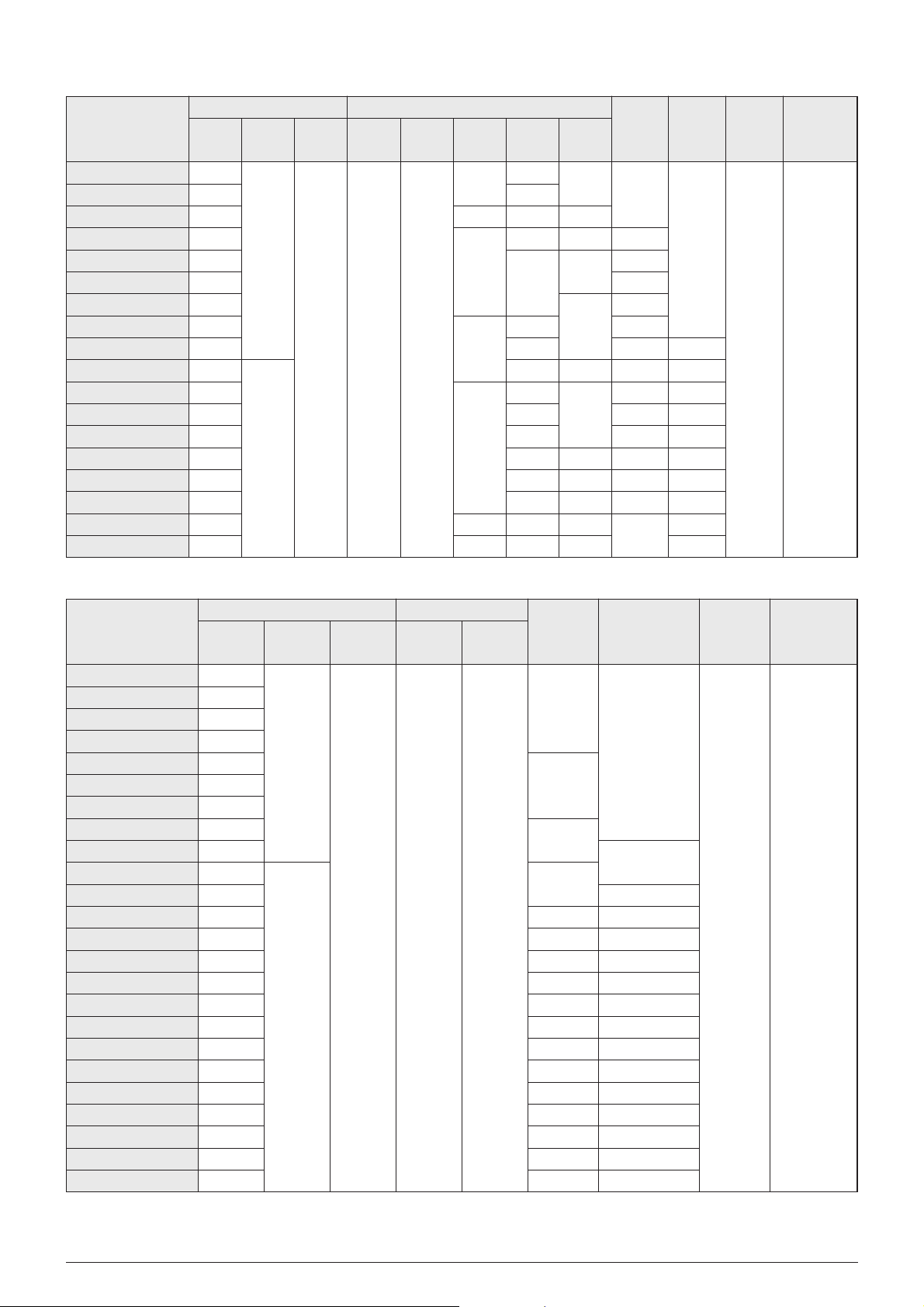
Application
General Frequency
Range
High-frequency
Range
Chokes
Part Number
LQH1N
LQH3N
LQH (N) 4N
LQG11N
LQG21N
LQS33N
1206
1210
1812
0603
0805
1214
0402
0603
0402
0603
0603
0805
1206
1206
1206
1210
1812
0805
0805
1206
2220
1212
2525
3Y7
8Y9
10Y11
12Y13
14Y16
17Y20
21Y23
24Y27
28
29Y31
32
33Y34
35Y36
39Y41
37Y38
39Y41
Wound coil
(ferrite core)
Magnetically shielded
multilayer
Magnetically shielded
Wound coil
(air core)
Multilayer
Thin film
Wound coil
(ferrite core)
Wound coil
Magnetically shielded
multilayer
Wound coil
Magnetically shielded
LQW1608A
LQN21A
LQN1A
LQN1H
LQG10A
LQG11A
LQP10A
LQP11A
Tight
inductance
tolerance
Tight
inductance
tolerance
Structure
Dimensions Inductance Range (H)
Page
1n 10n 100n 1µ 10µ 100µ 1m 10m
(mm) (inch)
LQH1C
LQH3C
LQH4C
LQG21C
LQG21F
LQG3216F
LQN6C
LQS33C
LQS66C
3.2
1.6
3.2
2.5
4.5
3.2
2.0
1.25
3.2
3.5
2.0
1.5
3.2
1.6
3.2
1.6
3.2
1.6
4.5
3.2
6.3
6.3
3.2
2.5
3.3
3.3
2.0
1.25
2.0
1.25
1.6
0.8
1.6
0.8
1.6
0.8
1.6
0.8
1.0
0.5
1.0
0.5
5.7
5.0
3.2
1.6
1
This is the PDF file of catalog No.O05E-5. No.O05E5.pdf 00.3.15This is the PDF file of catalog No.O05E-5. No.O05E5.pdf 00.3.15
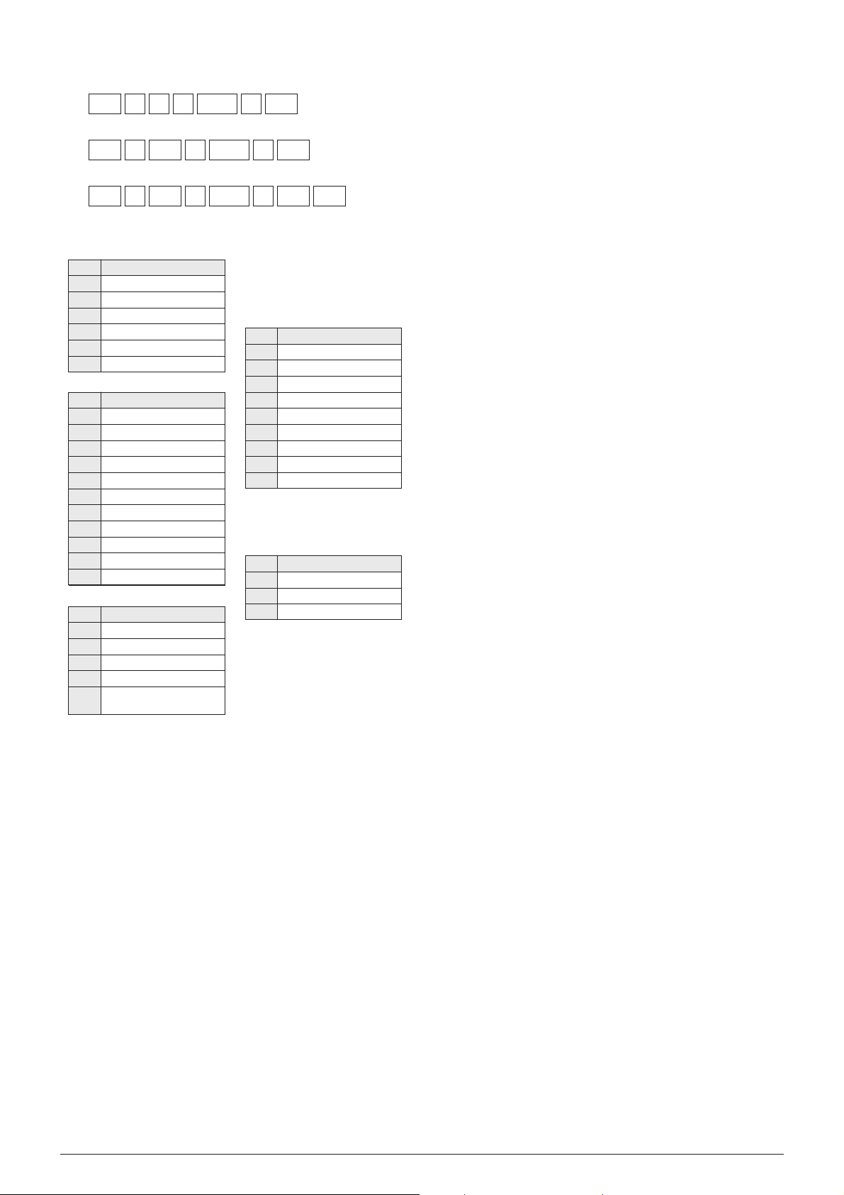
LQ
(Ex.)
H 3 N 331 K
!PART NUMBERING
(Please specify the part number when ordering.)
q w e r t y34u
LQ N 21 A 10N J
q w e r t y04u
LQ G 21 N R10 K
q w e r t y10uT1i
qChip Coil
wForm .Structure
eSize
Mark
1
3
4
6
10
11
21
33
66
1608
3216
Size
3.2Z1.6mm
3.2Z2.5mm
4.5Z3.2mm
5.7Z5.0mm
1.0Z0.5mm
1.6Z0.8mm
2.0Z1.25 (1.5) mm
3.2Z3.5mm, 3.3Z3.3mm
6.3Z6.3mm
1.6Z0.8mm
3.2Z1.6mm
rCharacteristic.Applications
Mark
N
C
A
H
F
Characteristic .Applications
General use
Choke coil
Air coil
High Q
For DC power supply
line choke coil
tInductance
Example
: 330µH/331 33nH/33N
33µH/330 3.3nH/3N3
3.3µH/3R3
0.33µH/R33
uAdditional Number
iPackaging Code
(LQG21N/21C/LQP10A/11A/
LQG10A/11A/LQW1608A)
yInductance Tolerance
Mark
G
J
K
M
N
B
C
S
D
Tolerance
T02%
T05%
T10%
T20%
T30%
T0.1nH
T0.2nH
T0.3nH
T0.5nH
Mark
T1
T2
B1
Packaging
Taped (
φ180mm Reel)
Taped (φ330mm Reel)
Bulk package
Mark
H
N
S
P
G
W
Form.Structure
Wire wound with coating
Wire wound without coating
Wire wound with shielded core
Thin film
Multilayer
Horizontal wire wound
2
This is the PDF file of catalog No.O05E-5. No.O05E5.pdf 00.3.15
0603
LQG11A
1.2-100nH
0402
LQG10A
1.2-33nH
1206
LQN1A
8.8-100nH
LQN21A
3.3-470nH
LQP11A
1.3-33nH
LQP10A
1.0-33nH
0805
0603
0402
1206
06031206
1812
1210
0805
LQG21C
1.0-47µH 7-60mA
LQH1N
0.15-100µH
LQH3N
0.10-560µH
LQH4N
1.0-2200µH
LQG11N
47-2200nH
0805
1214
LQS33N
1.0-100µH
LQG21N
0.1-4.7µH
LQN1H
54-880nH
LQH1C
0.12-100µH 80-970mA
LQH4C
1.0-470µH 90-1080mA
LQH3C
0.15-560µH 60-1450mA
0805
LQG21F
1.0-47µH 7-220mA
1206
LQG3216F
10µH 70mA
1812
1210
1206
LQS33C
560-2200µH20-50mA
1212
LQN6C/LQS66C
0.12-10000µH 0.05-6.0A
2220 2525
LQW1608A
2.2-220nH
0603
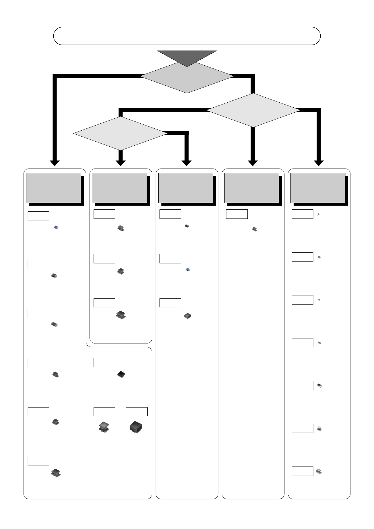
CHIP INDUCTOR SELECTION
Application
Operating
Frequency
Less than 50MHz
Choke
Impedance Matching
or
Resonance
Greater than
100MHz
30MHz
to
150MHz
Need
Magnetical
Shield
Start
Yes
No
Chip Inductor
for
Choke Use
Chip Inductor
for
General Frequency
Chip Inductor
for
Magnetical shield
Chip Inductor
for
Ultra High Frequency
Chip Inductor
for
High Frequency
This is the PDF file of catalog No.O05E-5. No.O05E5.pdf 00.3.15
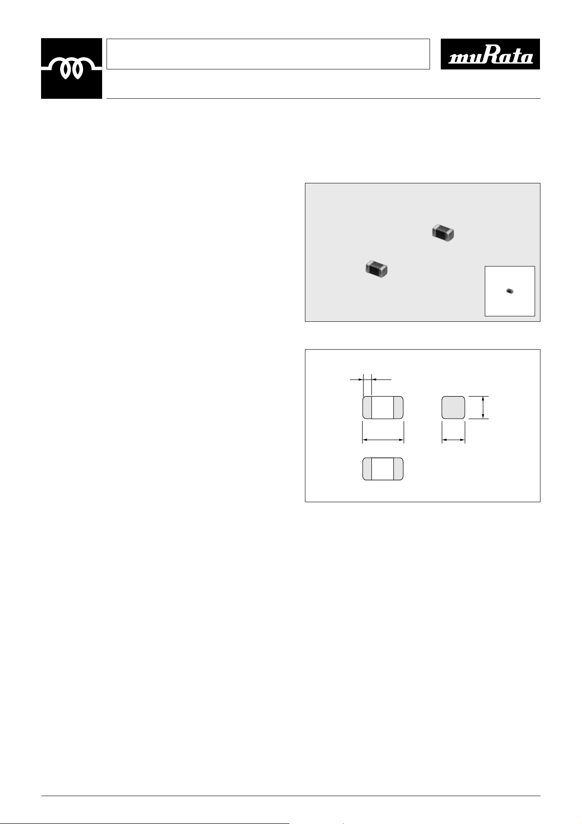
Standard Chip Coil LQH1N/LQH3N/LQH(N)4N Series
CHIP COIL
3
Wire Wound Chip Coil with High Q Value
at High Frequencies and Low DC Resistance
The chip coil LQH/LQN series consists of miniature
chip inductors wound on a special ferrite core and are
made possible by an automatic winding technique
developed by Murata. These inductors have a high Q at
high frequencies and low DC resistance, making them
very well suited to enhancing the performance of
electronic circuits in video, communications, and
audio equipment.
!FEATURES
1. There are three different inductor types: the
LQH1N,LQH3N and LQH(N)4N series. These three series
cover a wide inductance range (from 0.1µH to 2.2mH).
2. The series has outstanding frequency characteristics and
a high Q value at high frequencies.
3. The low DC resistance permits high current flow.
4. The series has excellent solder heat resistance. Both flow
and reflow soldering methods can be employed.
¡LQH1N
Miniature size (3.2Z1.6Z1.8mm) allows parallel
mounting at 2.5mm pitch. The series is suitable for
portable audio-visual equipment.
¡LQH3N
A high Q value makes this series suitable for circuits
up to 100MHz in frequency. The series is excellent for
video equipment.
¡LQH(N)4N
This series offers high inductance values
and high current capacity. At 10µH, up to 450mA
designs are possible, resulting in excellent
performance when the inductors are used as choke coils.
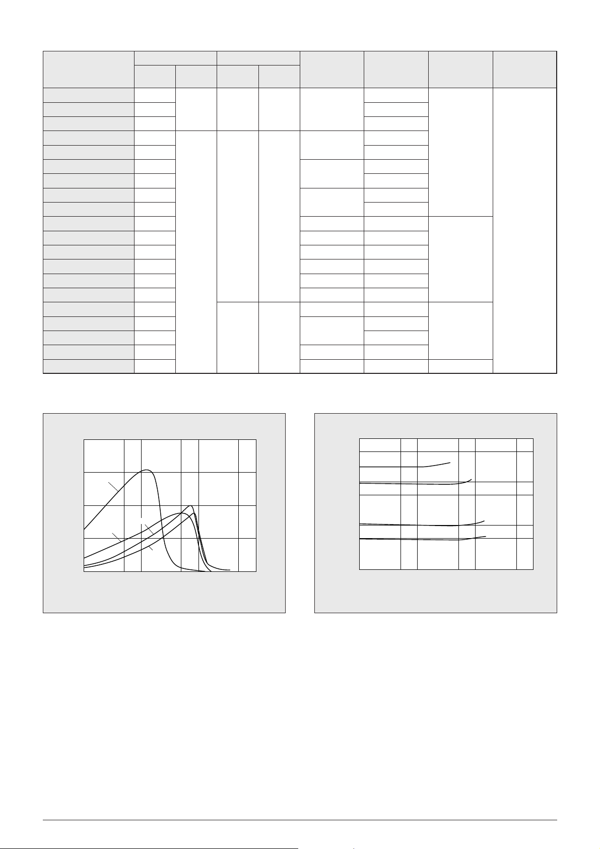
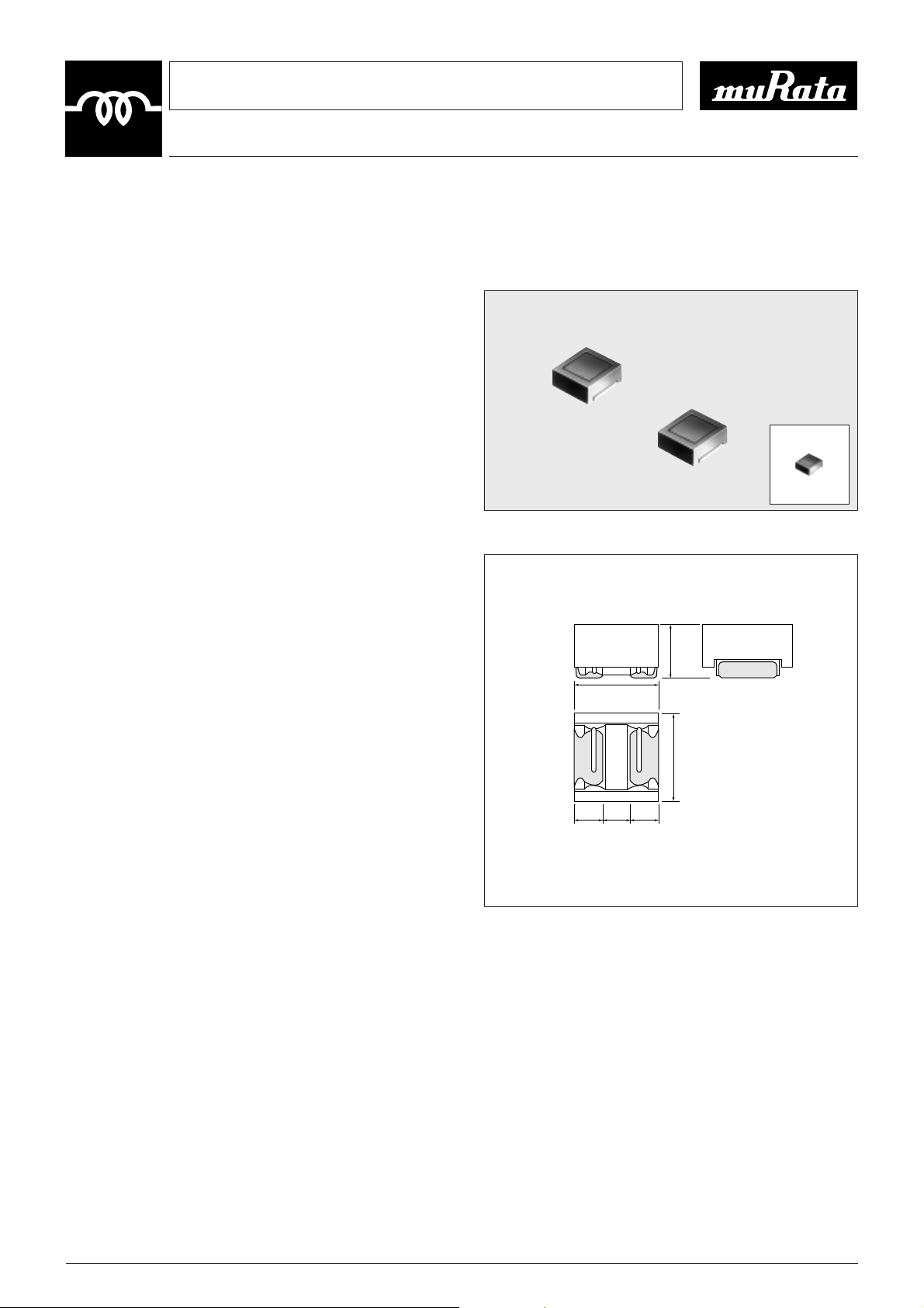
!DIMENSIONS
LQH1N Type
LQH4N/LQN4N Type
LQH3N Type
LQH1N Type
LQH3N Type
LQH4N/LQN4N Type
EIA Code:1210
2.3±0.2
3.2±0.3
1.8±0.2
1.6±0.2
1.6±0.2
0.7
min.
0.7
min.
0.7
min.
2.5±0.2
3.2±0.3
2.0±0.2
2.5±0.2
2.5±0.2
0.9
±0.3
0.9
±0.3
1.3
±0.2
3.6±0.2
4.5±0.3
2.6±0.2
3.2±0.2
3.2±0.2
1.0
min.
3.2±0.2
1.0
min.
1.0
min.
EIA Code:1206
EIA Code:1812
(in mm)
4
This is the PDF file of catalog No.O05E-5. No.O05E5.pdf 00.3.15
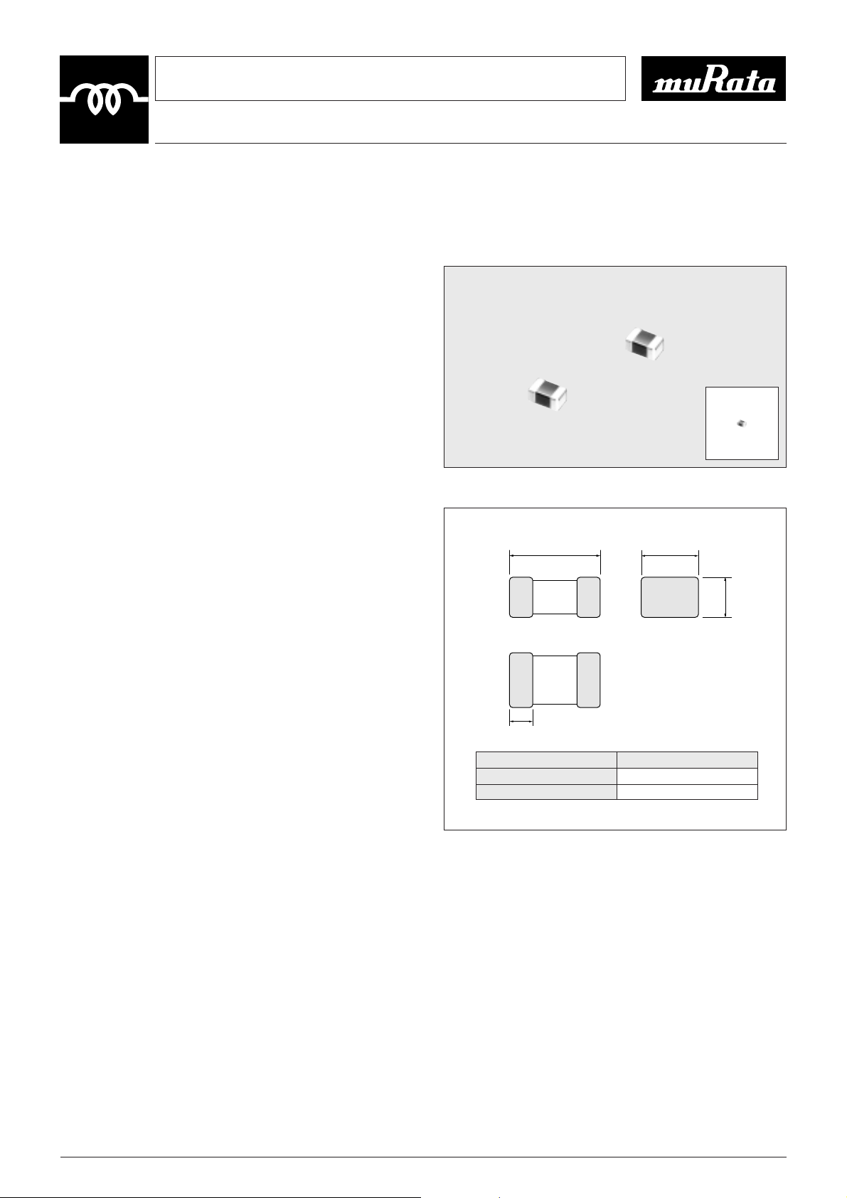
!SPECIFICATIONS
LQH1N
LQH1NR15K04 0.15
20
0.39T40% 250
LQH1NR22K04 0.22 0.43T40% 250 240
LQH1NR33K04 0.33 0.45T40% 230
LQH1NR47K04 0.47 25MHz 0.83T40% 200 215
LQH1NR56K04 0.56 T10 30 0.61T40% 180 200
LQH1NR68K04 0.68 0.67T40% 160 190
LQH1NR82K04 0.82 0.73T40% 120 185
LQH1N1R0K04 1.0 0.49T30% 100 175
LQH1N1R2K04 1.2 0.9 T30% 90 165
LQH1N1R5K(J)04 1.5
10MHz
1.0 T30% 75 155
LQH1N1R8K(J)04 1.8 1.6 T30% 60 150
LQH1N2R2K(J)04 2.2 0.7 T30% 50 140
LQH1N2R7K(J)04 2.7 0.55T30% 43 135
LQH1N3R3K(J)04 3.3 0.61T30% 38 130
LQH1N3R9K(J)04 3.9
35
1.5 T30% 35 125
Y25
LQH1N4R7K(J)04 4.7
1MHz
8MHz
1.7 T30% 31 120 to
LQH1N5R6K(J)04 5.6 1.8 T30% 28 115
W85D
LQH1N6R8K(J)04 6.8 2.0 T30% 25 110
LQH1N8R2K(J)04 8.2 2.2 T30% 23 105
LQH1N100K(J)04 10
T10
2.5 T30% 20 100
LQH1N120K(J)04 12
(T5)
5MHz
2.7 T30% 18 95
LQH1N150K(J)04 15 3.0 T30% 16 90
LQH1N180K(J)04 18 3.4 T30% 15
LQH1N220K(J)04 22 3.1 T30% 14 85
LQH1N270K(J)04 27 3.4 T30% 13
LQH1N330K(J)04 33 3.8 T30% 12 80
LQH1N390K(J)04 39 7.2 T30% 11
55
LQH1N470K(J)04 47 40 2.5MHz 8.0 T30% 10
LQH1N560K(J)04 56 8.9 T30% 9.0
50
LQH1N680K(J)04 68 9.9 T30% 8.5
LQH1N820K(J)04 82 11 T30% 7.5
45
LQH1N101K(J)04 100 12 T30% 7.0
Part Number
Inductance Q
Nominal
Value(µH)
Tolerance
(%)
Test
Frequency
Nominal
Value(min.)
Test
Frequency
DC Resistance
(Ω)
Self-resonant
Frequency
(MHz min.)
Allowable
Current
(mA)
Operating
Temp. Range
5
This is the PDF file of catalog No.O05E-5. No.O05E5.pdf 00.3.15This is the PDF file of catalog No.O05E-5. No.O05E5.pdf 00.3.15
LQH3NR10M34 0.10
20
700
LQH3NR18M34 0.18
200
650
LQH3NR27M34 0.27
25
600
LQH3NR39M34 0.39 25.2MHz 0.25
530
LQH3NR56M34 0.56 T20
160
LQH3NR68M34 0.68 30 470
LQH3NR82M34 0.82 120 450
LQH3N1R0M34 1.0 0.5
100
445
LQH3N1R2M34 1.2
0.6
425
LQH3N1R5K34 1.5 75 400
LQH3N1R8K34 1.8 0.7 60 390
LQH3N2R2K34 2.2 0.8 50 370
LQH3N2R7K34 2.7 20 0.9 43 320
LQH3N3R3K34 3.3
T10
1.0 38 300
LQH3N3R9K34 3.9 1.1 35 290
LQH3N4R7K34 4.7 1.2 31 270
LQH3N5R6K34 5.6 1.3 28 250
LQH3N6R8K34 6.8 1.5 25 240
Y25
LQH3N8R2K34 8.2
1MHz 1MHz
1.6 23 225 to
LQH3N100K(J)34 10 1.8 20 190
W85D
LQH3N120K(J)34 12 2.0 18 180
LQH3N150K(J)34 15
35
2.2 16 170
LQH3N180K(J)34 18 2.5 15 165
LQH3N220K(J)34 22 2.8 14 150
LQH3N270K(J)34 27 3.1 13 125
LQH3N330K(J)34 33 3.5 12 115
LQH3N390K(J)34 39 3.9
11
110
LQH3N470K(J)34 47 4.3 100
LQH3N560K(J)34 56 4.9 10 85
LQH3N680K(J)34 68
T10
5.5 9.0 80
LQH3N820K(J)34 82
(T5)
6.2 8.5 70
LQH3N101K(J)34 100 40 7.0 8.0 80
LQH3N121K(J)34 120 8.0 7.5 75
LQH3N151K(J)34 150 9.3 7.0 70
LQH3N181K(J)34 180 10.2 6.0
LQH3N221K(J)34 220 11.8 5.5
65
LQH3N271K(J)34 270
796kHz
12.5
LQH3N331K(J)34 330 13.0
LQH3N391K(J)34 390 22.0 5.0 50
LQH3N471K(J)34 470
1kHz
50 25.0 45
LQH3N561K(J)34 560 28.0 40
Part Number
Inductance Q
Nominal
Value(µH)
Tolerance
(%)
Test
Frequency
Nominal
Value(min.)
Test
Frequency
DC Resistance
(Ωmax.)
Self-resonant
Frequency
(MHz min.)
Allowable
Current
(mA)
Operating
Temp. Range
LQH3N
6
This is the PDF file of catalog No.O05E-5. No.O05E5.pdf 00.3.15
LQH4N1R0M04 1.0
0.20
120
LQH4N1R2M04 1.2 100
LQH4N1R5M04 1.5 85
LQH4N1R8M04 1.8
T20 20
0.30 75
LQH4N2R2M04 2.2 62 500
LQH4N2R7M04 2.7 0.32 53
LQH4N3R3M04 3.3 0.35 47
LQH4N3R9M04 3.9 0.38 41
LQH4N4R7K04 4.7 0.40 38
LQH4N5R6K04 5.6 0.47 33
LQH4N6R8K04 6.8
T10 30
0.50 31
450
LQH4N8R2K04 8.2
1MHz
0.56
27
LQH4N100K(J)04 10 23 400
LQH4N120K(J)04 12 0.62 21 380
LQH4N150K(J)04 15 0.73 19 360
LQH4N180K(J)04 18 1MHz 0.82 17 340
LQH4N220K(J)04 22 0.94 15 320
LQH4N270K(J)04 27 1.1 14 300
Y25
LQH4N330K(J)04 33
35
1.2 12 270 to
LQH4N390K(J)04 39 1.4 11 240
W85D
LQH4N470K(J)04 47 1.5 10 220
LQH4N560K(J)04 56 1.7 9.3 200
LQH4N680K(J)04 68 1.9 8.4 180
LQH4N820K(J)04 82 2.2 7.5 170
LQH4N101K(J)04 100 2.5 6.8 160
LQH4N121K(J)04 120 3.0 6.2 150
LQH4N151K(J)04 150
T10
3.7 5.5 130
LQH4N181K(J)04 180
(T5)
4.5 5.0 120
LQH4N221K(J)04 220 5.4 4.5 110
LQH4N271K(J)04 270
796kHz
6.8 4.0 100
LQH4N331K(J)04 330 8.2 3.6 95
LQH4N391K(J)04 390 9.7 3.3 90
LQH4N471K(J)04 470 40 11.8 3.0 80
LQH4N561K(J)04 560 14.5 2.7 70
LQH4N681K(J)04 680 17.0 2.5 65
LQH4N821K(J)04 820 20.5 2.2 60
LQH4N102K(J)04 1000 1kHz 25.0 2.0 50
LQH4N122K(J)04 1200 30.0 1.8 45
LQH4N152K(J)04 1500 252kHz 37.0 1.6 40
LQN4N182K(J)04 1800 45.0 1.5 35
LQN4N222K(J)04 2200 50.0 1.3 30
Part Number
Inductance Q
Nominal
Value(µH)
Tolerance
(%)
Test
Frequency
Nominal
Value(min.)
Test
Frequency
DC Resistance
(Ωmax.)
Self-resonant
Frequency
(MHz min.)
Allowable
Current
(mA)
Operating
Temp. Range
LQH4N/LQN4N
7
This is the PDF file of catalog No.O05E-5. No.O05E5.pdf 00.3.15This is the PDF file of catalog No.O05E-5. No.O05E5.pdf 00.3.15
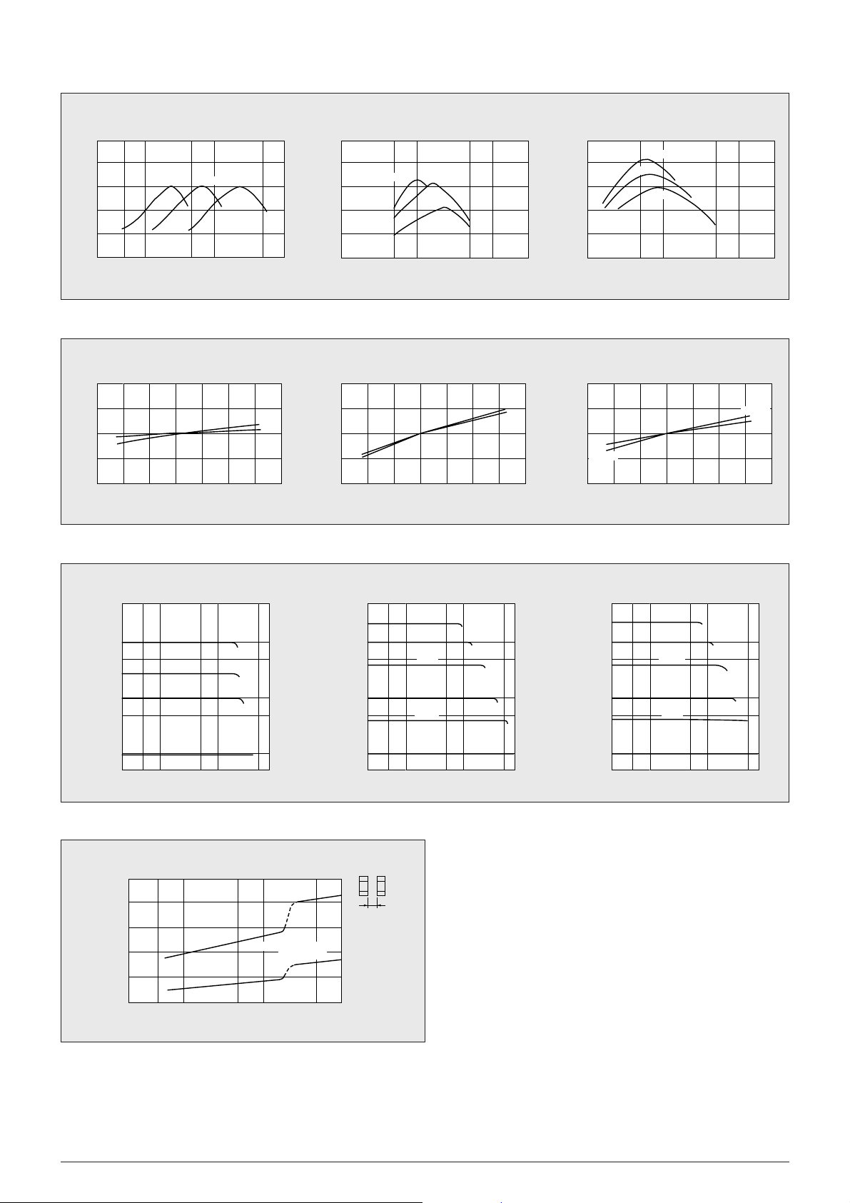
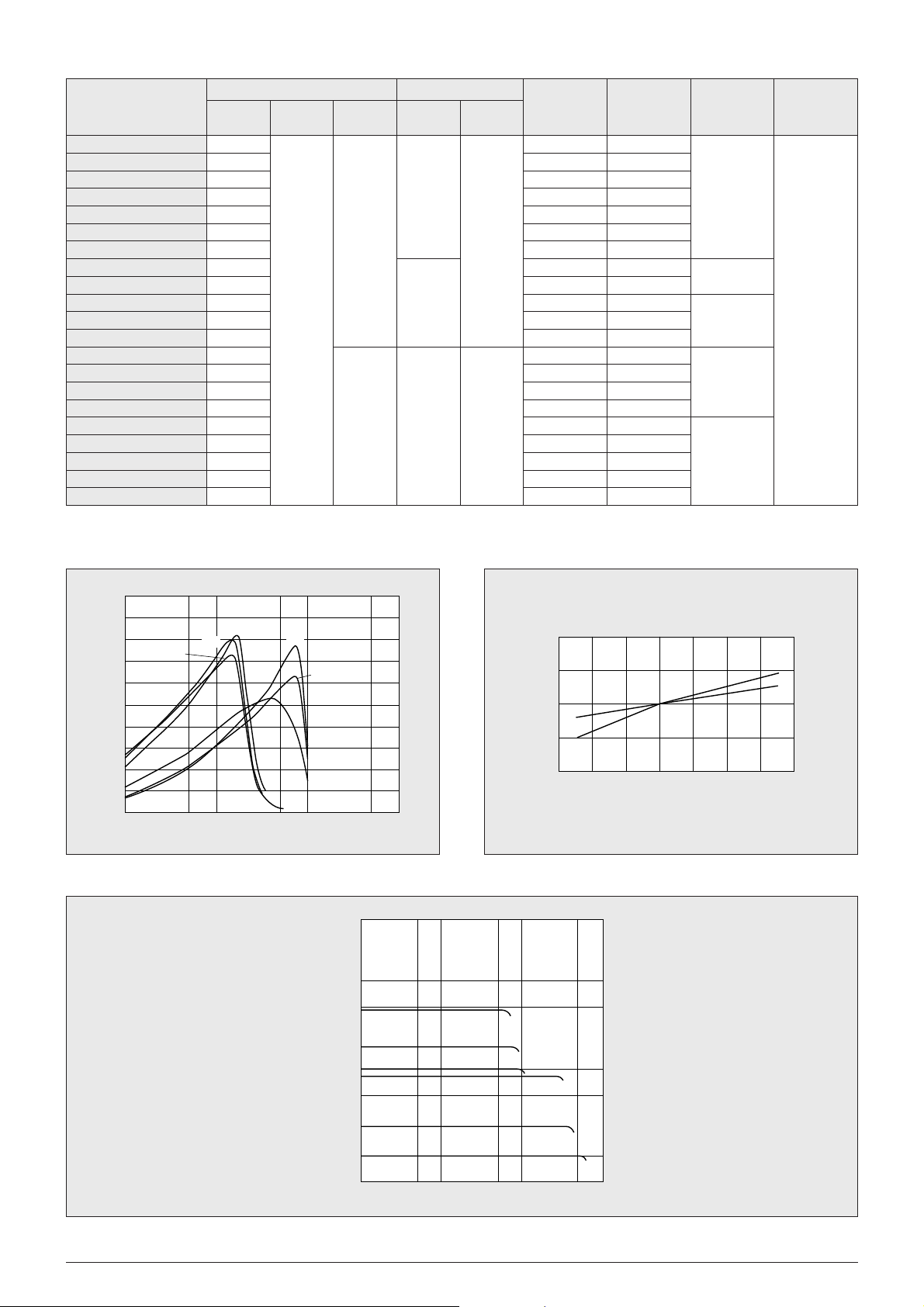
!TYPICAL ELECTRICAL CHARACTERISTICS
¡Q - Frequency Characteristics
¡Inductance - Temperature Characteristics
¡Inductance - Current Characteristics
¡Coupling Coefficient
100
80
60
40
20
0
0.1
Q
100
80
60
40
20
0
0.1
Q
100
80
60
40
20
0
Q
Frequency (MHz)
0.5 1 5 10 50 100
0.5 1
Frequency (MHz)
5 10 0.5 1
Frequency (MHz)
510
1000µH
100µH
10µH
1µH
100µH
10µH
1µH
100µH
10µH
LQH3N LQH4N/LQN4NLQH1N
LQH3N LQH4N/LQN4NLQH1N
LQH3N LQH4N/LQN4NLQH1N
10
8
6
4
2
0
0.5 1 5 10 50 100
Inductance (µH)
Coupling Coefficient (%)
R
R=0.9mm
R=2.0mm
(2.5mm Pitch Parallel
Mounting)
LQH1N
10
5
0
∆L/L (%)
-
5
-
10
-
20
020
Temperature (D)
40 60 80
100µH
1µH
500
100
50
10
Inductance (µH)
5
1
100µH
33µH
10µH
1.0µH
510 50
Current (mA)
100 500 5 10 50
10
5
0
∆L/L (%)
-
5
-
10
-
20 0 20
500
100
50
10
Inductance (µH)
5
1
40 60 80
Temperature (D)
220µH
100µH
39µH
10µH
3.9µH
1.0µH
Current (mA)
10
220µH
1.0µH
100 500 5 10 50
5
0
∆L/L (%)
-
5
-
10
10µH
1000µH
5000
1000
500
100
Inductance (µH)
50
10
-
20 0 20
Temperature (D)
2200µH
1000µH
390µH
100µH
39µH
10µH
Current (mA)
1000µH
10µH
40 60 80
100 500
!DIMENSIONS
Multilayer Chip Inductor
LQG11N
Series
CHIP COIL
8
This is the PDF file of catalog No.O05E-5. No.O05E5.pdf 00.3.15
Magnetically Shielded Multilayer Chip Coil
Excellent for High Density Mounting
The LQG11N series, of magnetically shielded chip coil was
developed by using original multilayer process technology and
magnetic materials.
Compact size is suitable for high density mounting.
Shielded construction is not affected by interference from
peripheral components.
!FEATURES
1. Magnetically shielded structure provides excellent
characteristics in cross talk and magnetic coupling.
2. Compact size (1.6Z0.8mm) and light weight.
3. The external electrodes with nickel barrier structure provide
excellent solder heat resistance. Both flow and reflow
soldering can be applicable.
!APPLICATIONS
¡Resonance circuit, traps, filter circuits and RF choke in
telecommunication equipments, cordless phones, radio
equipments.
(in mm)
0.4±0.2
1.6±0.15
0.8±0.15
0.8±0.15
9
This is the PDF file of catalog No.O05E-5. No.O05E5.pdf 00.3.15This is the PDF file of catalog No.O05E-5. No.O05E5.pdf 00.3.15
¡Inductance-Frequency Characteristics
!SPECIFICATIONS
!TYPICAL ELECTRICAL CHARACTERISTICS
¡Q-Frequency Characteristics
Part Number
LQG11N47NM00
LQG11N68NM00
LQG11N82NM00
LQG11NR10K00
LQG11NR12K00
LQG11NR15K00
LQG11NR18K00
LQG11NR22K00
LQG11NR27K00
LQG11NR33K00
LQG11NR39K00
LQG11NR47K00
LQG11NR56K00
LQG11NR68K00
LQG11NR82K00
LQG11N1R0K00
LQG11N1R2K00
LQG11N1R5K00
LQG11N1R8K00
LQG11N2R2K00
Inductance Q
DC
Resistance
(Ω max.)
Self-resonant
Frequency
(MHz min.)
Allowable
Current
(mA)
Operating
Temp. Range
Nominal
Value (nH)
Nominal
Value(min.)
Test Frequency
(MHz)
1047
1068
1082
1100
1120
1150
1180
1220
1270
1330
1390
1470
1560
1680
1820
1000
1200
1500
1800
2200
Tolerance
(%)
T20
T10
10
15
35
50
25
10
0.30
0.50
0.60
0.80
0.85
1.00
1.35
1.55
1.70
2.10
0.60
0.80
0.95
1.15
260
250
245
240
205
180
165
150
136
125
110
105
95
90
85
75
65
60
55
50
50
35
25
15
Y25 to W85D
Measuring instrument Q : HP4291A+16192A Measuring instrument L : HP4291A+16192A
80
60
2200nH
40
Q
820nH
20
0
1 10 100 1000
100nH
47nH
Frequency (MHz)
10000
2200nH
1000
Inductance (nH)
100
1
1 10 100 1000
Frequency (MHz)
820nH
100nH
47nH
This is the PDF file of catalog No.O05E-5. No.O05E5.pdf 00.3.15
!DIMENSIONS
Multilayer Chip Coil
LQG21N
Series
CHIP COIL
10
Magnetically Shielded Multilayer Chip Coil
Low Drift Excellent for High Density Mounting
The LQG21N series consists of magnetically shielded chip
coils developed using original Murata multilayer process
technology and magnetic materials.
The coils occupy one quarter the volume of conventional
chip coils and feature high reliability.
!FEATURES
1. Magnetically shielded structure provides excellent
crosstalk characteristics.
2. Compact (2.0Z1.25mm) and lightweight.
3. Low inductance drift resulting from
soldering,environmentaltests, etc.
4. Outstanding solder heat resistance. Either flow or reflow
soldering can be used.
!APPLICATIONS
¡Hard-disk drives
¡Audio-Visual equipment
¡Telecommunications equipment
Part Number T
LQG21NR10K10Y2R2K10 0.85T0.2
LQG21N2R7K10Y4R7K10 1.25T0.2
(in mm)
EIA Code:0805
2.0±0.3 1.25±0.2
T
0.5±0.3
11
This is the PDF file of catalog No.O05E-5. No.O05E5.pdf 00.3.15This is the PDF file of catalog No.O05E-5. No.O05E5.pdf 00.3.15
!SPECIFICATIONS
Part Number
Inductance Q
Nominal
Value(µH)
Tolerance
(%)
Test
Frequency
Nominal
Value(min.)
Test
Frequency
DC Resistance
(Ω max.)
Self-resonant
Frequency
(MHz min.)
Operating
Temp. Range
!TYPICAL ELECTRICAL CHARACTERISTICS
¡Q - Frequency Characteristics
¡Inductance - Temperature Characteristics
¡Inductance - Current Characteristics
Allowable
Current
(mA)
LQG21NR10K10 0.10 0.26 340
LQG21NR12K10 0.12 0.29 310
LQG21NR15K10 0.15 0.32 270
LQG21NR18K10 0.18 20 0.35 250 250
LQG21NR22K10 0.22 0.38 220
LQG21NR27K10 0.27 25MHz 25MHz 0.42 200
LQG21NR33K10 0.33 0.48 180
LQG21NR39K10 0.39 0.53 165
200
LQG21NR47K10 0.47 0.57 150
LQG21NR56K10 0.56 25 0.63 140 Y40
LQG21NR68K10 0.68 T10 0.72 125 150 to
LQG21NR82K10 0.82 0.81 115 W85D
LQG21N1R0K10 1.0 0.40 107
LQG21N1R2K10 1.2 0.47 97
50
LQG21N1R5K10 1.5 0.50 87
LQG21N1R8K10 1.8 0.57 80
LQG21N2R2K10 2.2 10MHz 45 10MHz 0.63 71
LQG21N2R7K10 2.7 0.69 66
LQG21N3R3K10 3.3 0.80 59 30
LQG21N3R9K10 3.9 0.89 53
LQG21N4R7K10 4.7 1.00 47
1
0.5
0.1
5
10
50
5051 10 100 500
Inductance (
µH)
Current (mA)
4.7µH
1.8µH
1.0µH
0.22µH
0.10µH
0.82µH
100
80
60
Q
40
20
0
4R7
1 10 100 1000
1R0
1R8
Frequency (MHz)
R10
R22
R82
10
5
0
L/L(%)
-5
-10
-20 0 20 40 60 80
Temperature (°C)
0.1µH
4.7µH
This is the PDF file of catalog No.O05E-5. No.O05E5.pdf 00.3.15
!DIMENSIONS
Small Tolerance Chip Coil
LQS33N
Series for Oscillation Circuits
CHIP COIL
12
High Q, Magnetically Shielded Chip Coil with Tight Inductance
Tolerance (T2%), Perfect in Oscillation Circuits
The LQS33N series consists of closed, magnetically
shielded chip inductors wound on ferrite bobbins developed
by Murata.
Their high Q value virtually eliminates interference with
nearby circuits. This, combined with their tight inductance
tolerance, makes these chip inductors excellent in resonant
circuits.
!FEATURES
1. The coil's outstanding stability yields a reduction in
inductor tolerance to within T2%.
2. Its high Q (typically greater than 80) is present at all
inductance values and is the basis of this chip coil's
outstanding low loss circuit characteristics.
3. The ferrite core shielding structure both eliminates
external interference and facilitates high mounting
density.
4. Small inductance variation with respect to temperature
change makes these coils applicable in traps or LC filters
for stable frequency characteristics.
5.
This series is thin and compact, with a thickness of merely
1.8mm.
(in mm)
EIA Code:1214
1.8±0.2
+0.3
3.2
-0.2
0.7
min.
0.7
min.
min.
+0.3
-0.2
3.5
0.7

13
This is the PDF file of catalog No.O05E-5. No.O05E5.pdf 00.3.15This is the PDF file of catalog No.O05E-5. No.O05E5.pdf 00.3.15
!TYPICAL ELECTRICAL CHARACTERISTICS
¡Q - Frequency Characteristics ¡Inductance - Temperature Characteristics
¡Inductance - Current Characteristics
!SPECIFICATIONS
Part Number
Inductance Q
Nominal
Value(µH)
Tolerance
(%)
Test
Frequency
Peak Value
(Typ.)
Min.
Value
Test
Frequency
DC
Resistance
(Ω)
Self-resonant
Frequency
(MHz min.)
Allowable
Current
(mA)
Operating
Temp. Range
80
100
60
40
20
0
120
5050.1 0.5 1 10 100
Frequency (MHz)
Q
1.0µH
100µH
10µH
¡Coupling Coefficient
LQS33N1R0G(J)04 1.0 0.19T30% 120
LQS33N1R2G(J)04 1.2
85
0.22T30% 100
70
LQS33N1R5G(J)04 1.5 0.26T30% 80
LQS33N1R8G(J)04 1.8 0.28T30% 70
LQS33N2R2G(J)04 2.2 0.33T30% 60
LQS33N2R7G(J)04 2.7 0.39T30% 55
50
LQS33N3R3G(J)04 3.3 7.96 60 7.96 0.43T30% 50
LQS33N3R9G(J)04 3.9
MHz MHz
0.45T30% 45
LQS33N4R7G(J)04 4.7 0.52T30% 40
LQS33N5R6G(J)04 5.6 0.56T30% 37
30
LQS33N6R8G(J)04 6.8 90 0.62T30% 35
LQS33N8R2G(J)04 8.2 T2 0.69T30% 32 Y25
LQS33N100G(J)04 10 (T5) 0.94T30% 30 to
LQS33N120G(J)04 12 1.1 T30% 27
15
W85D
LQS33N150G(J)04 15
70
1.2 T30% 25
LQS33N180G(J)04 18 1.3 T30% 23
LQS33N220G(J)04 22 1.5 T30% 20
LQS33N270G(J)04 27
2.52 2.52
1.7 T30% 18
LQS33N330G(J)04 33
MHz
95
MHz
2.4 T30% 16
LQS33N390G(J)04 39 2.6 T30% 15
LQS33N470G(J)04 47 3.0 T30% 14 10
LQS33N560G(J)04 56 80 3.3 T30% 13
LQS33N680G(J)04 68
100
5.3 T30% 12
LQS33N820G(J)04 82 5.8 T30% 11
LQS33N101G(J)04 100 6.6 T30% 10
10
5
L/L
0
(%)
-5
-10
-20 0 20 40 60 80
Temperature (°C)
500
100
50
µH)
10
Inductance (
5
1
100µH
4.7µH
2.2µH
1.0µH
Current (mA)
47µH
22µH
10µH
505 10 100 500
10
8
6
4
2
Coupling Coefficient (%)
0
Inductance (
µH
)
100µH
1mm
501 5 10 100
This is the PDF file of catalog No.O05E-5. No.O05E5.pdf 00.3.15
!DIMENSIONS
Multilayer Chip Inductor
LQG10A/11A
Series for High Frequency
CHIP COIL
14
High-Q, Stable Inductance in High Frequency Range Small
Size Multilayer Chip Inductor for High Frequency Range
The LQG10A/11A series are chip inductors specifically
designed for high frequency applications. The LQG10A/11A
series is designed to realize stable characteristics in high
frequency range applying integrated multilayer process. The
integrated multilayer process enables a wide range of
inductance values with tight tolerance.
!FEATURES
1. High-Q, stable inductance in high frequency is achieved
by the unique low-capacitance structure. It is suitable for
mobile communication equipment.
2. The small size of LQG10A (1.0Z0.5Z0.5mm) is ideal for
small mobile equipment.
3. The external electrodes with nickel barrier structure
provide excellent solder heat resistance.
!APPLICATIONS
¡High frequency circuit of telecommunication equipment
such as CDMA, DECT, PHS, PCS, PCN, GSM and DCS.
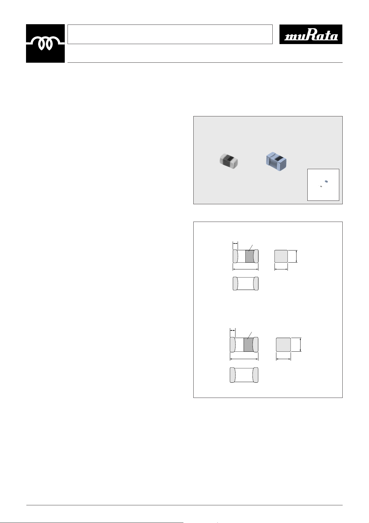
LQG10A
LQG11A
LQG10A LQG11A
(in mm)
EIA Code:0603
EIA Code:0402
0.25±0.1
Direection Indicator
0.5±0.1
0.3±0.2
1.0±0.1
Direction Indicator
1.6±0.15
0.5±0.1
0.8±0.15
0.8±0.15
15
This is the PDF file of catalog No.O05E-5. No.O05E5.pdf 00.3.15This is the PDF file of catalog No.O05E-5. No.O05E5.pdf 00.3.15
!SPECIFICATIONS
LQG10A
LQG11A
Part Number
LQG10A1N2S00
LQG10A1N5S00
LQG10A1N8S00
LQG10A2N2S00
LQG10A2N7S00
LQG10A3N3S00
LQG10A3N9S00
LQG10A4N7S00
LQG10A5N6S00
LQG10A6N8J00
LQG10A8N2J00
LQG10A10NJ00
LQG10A12NJ00
LQG10A15NJ00
LQG10A18NJ00
LQG10A22NJ00
LQG10A27NJ00
LQG10A33NJ00
Inductance Q
DC
Resistance
(Ω max.)
Self-
resonant
Frequency
(MHz min)
Allowable
Current
(mA)
Operating
Temp. Range
Nominal
Value
(nH)
Tolerance
Test
Frequency
(MHz)
800MHz
(typ.)
Nominal
Value
(min.)
01.2
01.5
01.8
02.2
02.7
03.3
03.9
04.7
05.6
06.8
08.2
10.0
12.0
15.0
18.0
22.0
27.0
33.0
T0.3nH
T5%
100
35
33
31
30
29
30
29
29
31
30
31
30
29
28
27
23
1GHz
(typ.)
38
34
33
32
33
32
34
33
32
31
27
24
8
Test
Frequency
(MHz)
500MHz
(typ.)
100
25
24
22
23
24
23
22
0.10
0.15
0.17
0.19
0.19
0.23
0.26
0.29
0.33
0.35
0.41
0.46
0.51
0.58
0.67
6000
5300
4200
3600
3200
2800
2300
2100
1800
1600
1500
200
Y40
to
W85
D
Inductance Q
Part Number
LQG11A1N2S00 1.2
LQG11A1N5S00 1.5
0.10
LQG11A1N8S00 1.8
LQG11A2N2S00 2.2
6000
LQG11A2N7S00 2.7 T0.3nH
LQG11A3N3S00 3.3 0.15
LQG11A3N9S00 3.9
LQG11A4N7S00 4.7
0.20
LQG11A5N6S00 5.6
5000
LQG11A6N8J(K)00 6.8
LQG11A8N2J(K)00 8.2
0.25
4000
LQG11A10NJ(K)00 10 0.30 3500
Y40
LQG11A12NJ(K)00 12
100 12 100
0.35 3000
300
to
LQG11A15NJ(K)00 15 0.40 2800
W85D
LQG11A18NJ(K)00 18 0.45 2600
LQG11A22NJ(K)00 22
T5%
0.50 2300
LQG11A27NJ(K)00 27
(T10%)
0.55 2000
LQG11A33NJ(K)00 33 0.60 1700
LQG11A39NJ(K)00 39 0.65 1500
LQG11A47NJ(K)00 47 0.70 1200
LQG11A56NJ(K)00 56 0.75 1100
LQG11A68NJ(K)00 68 0.80 1000
LQG11A82NJ(K)00 82 0.85 900
LQG11AR10J(K)00 100 0.90 800
Nominal
Value
(nH)
Tolerance
Test
Frequency
(MHz)
Nominal
Value
(min.)
Test
Frequency
(MHz)
DC
Resistance
(Ω max.)
Self-
resonant
Frequency
(MHz min.)
Allowable
Current
(mA)
Operating
Temp.
Range

16
!TYPICAL ELECTRICAL CHARACTERISTICS
"Q-Frequency Characteristics "Inductance - Frequency Characteristics
Measuring instrument Q : HP8720C, SMA connector
(MM1215-3CC)
Measuring instrument L : HP8720C, SMA connector
(MM1215-3CC)
LQG10A LQG10A
100
1000
10000
Frequency (MHz)
200
160
120
80
40
0
Q
3.3nH
10nH
68nH
100 1000 10000
Frequency (MHz)
1000
100
10
1
Inductance (nH)
68nH
10nH
3.3nH
LQG11A LQG11A
This is the PDF file of catalog No.O05E-5. No.O05E5.pdf 00.3.15
100
80
1.5nH
60
Q
40
20
0
100
33nH
1000
Frequency (MHz)
4.7nH
12nH
10000
1000
100
10
Inductance (nH)
1
100 1000 10000
33nH
12nH
Frequency (MHz)
4.7nH
1.5nH

This is the PDF file of catalog No.O05E-5. No.O05E5.pdf 00.3.15
!DIMENSIONS
Thin Film Chip Coil
LQP10A/LQP11A
Series for High Frequency
CHIP COIL
17
Tight Inductance Tolerance Chip Coil for High Frequency Application
Small Size and Tight Inductance Tolerance (T0.2nH or T2%)
The LQP10A/LQP11A series consists of chip coils with a
tight inductance tolerance (T0.2nH or T2%) achieved even
in low inductance region.
!FEATURES
1. Tight inductance tolerance (T0.2nH, T2%) realized by
thin-film technology enables assemble with no tuning.
2. High self resonant frequency due to low stray capacitance
and close inductance distribution provide stable
inductance in high frequency circuit such as
telecommunication equipment.
3. The external electrodes with nickel barrier structure
provide excellent solder heat resistance.
¡LQP10A
Ultra-Small size 0402 inductor which is low, and lightest
weight (half of multilayer type) in the world enables to
miniaturize mobile telephone.
¡LQP11A
Small size of 0603 (LQP11A) is suitable for small hand
held equipment, especially for card size equipment.
!APPLICATIONS
¡High frequency circuit of telecommunication equipment,
such as DECT, PHS, PCS, PCN, GSM, DCS and CDMA.
¡Impedance Matching—Power-AMP Module (PA), SAW
filter
¡Resonance circuits—VCO
The appearance of coil pattern depends on the part number.
LQP11ALQP10A
1.6±0.15
0.2 min.
0.8±0.15
0.5T0.1
1.0T0.15
0.25T0.1
0.5T0.15
0.35T0.1
1.6±0.15
0.2 min.
0.8±0.15
0.5T0.1
1.0T0.15
0.25T0.1
0.5T0.15
0.35T0.1
Use plastic tweezers when treating with tweezers.
LQP10A
LQP11A
(in mm)
EIA Code : 0603
EIA Code : 0402

18
This is the PDF file of catalog No.O05E-5. No.O05E5.pdf 00.3.15
!SPECIFICATIONS
LQG10A
Part Number
LQP10A1N0B(C)00
LQP10A1N1B(C)00
LQP10A1N2B(C)00
LQP10A1N3B(C)00
LQP10A1N5B(C)00
LQP10A1N6B(C)00
LQP10A1N8B(C)00
LQP10A2N0B(C)00
LQP10A2N2B(C)00
LQP10A2N4B(C)00
LQP10A2N7B(C)00
LQP10A3N0B(C)00
LQP10A3N3B(C)00
LQP10A3N6B(C)00
LQP10A3N9B(C)00
LQP10A4N3B(C)00
LQP10A4N7B(C)00
LQP10A5N1B(C)00
LQP10A5N6B(C)00
LQP10A6N2B(C)00
LQP10A6N8B(C)00
LQP10A7N5B(C)00
LQP10A8N2B(C)00
LQP10A9N1B(C)00
LQP10A10NG(J)00
LQP10A12NG(J)00
LQP10A15NG(J)00
LQP10A18NG(J)00
LQP10A22NG(J)00
LQP10A27NG(J)00
LQP10A33NG(J)00
Inductance Q
DC
Resistance
(Ω max.)
Self-resonant
Frequency
(MHz min)
Allowable
Current
(mA)
Operating
Temp. Range
Nominal
Value
(nH)
Tolerance
Test
Frequency
(MHz)
Typical
@1GHz
Min.
Value
1.0
1.1
1.2
1.3
1.5
1.6
1.8
2.0
2.2
2.4
2.7
3.0
3.3
3.6
3.9
4.3
4.7
5.1
5.6
6.2
6.8
7.5
8.2
9.1
10.0
12.0
15.0
18.0
22.0
27.0
33.0
T0.1nH
(T0.2nH)
T2%
(T5%)
500
50
45
40
35
30
28
29
26
25
22
21
13
Test
Frequency
(MHz)
500
0.1
0.2
0.3
0.2
0.3
0.4
0.5
0.6
0.7
0.9
1.1
1.3
1.6
1.8
2.0
2.6
3.1
3.8
6000
5500
4500
3700
3300
3100
2800
2500
2100
400
390
280
220
280
220
190
170
160
140
130
110
100
90
80
70
60
Y40
to
W85D

19
This is the PDF file of catalog No.O05E-5. No.O05E5.pdf 00.3.15This is the PDF file of catalog No.O05E-5. No.O05E5.pdf 00.3.15
LQG11A
Part Number
LQP11A1N3C00
LQP11A1N5C00
LQP11A1N8C00
LQP11A2N2C00
LQP11A2N7C00
LQP11A3N3C00
LQP11A3N9C00
LQP11A4N7C00
LQP11A5N6C00
LQP11A6N8C00
LQP11A8N2C00
LQP11A10NG00
LQP11A12NG00
LQP11A15NG00
LQP11A18NG00
LQP11A22NG00
LQP11A27NG00
LQP11A33NG00
LQP11A39NG00
LQP11A47NG00
LQP11A56NG00
LQP11A68NG00
LQP11A82NG00
LQP11AR10G00
Inductance Q
DC
Resistance
(Ω max.)
Self-resonant
Frequency
(MHz min)
Allowable
Current
(mA)
Operating
Temp. Range
Nominal
Value
(nH)
Tolerance
Test
Frequency
(MHz)
Peak
Value
(Typ.)
Min.
Value
01.3
01.5
01.8
02.2
02.7
03.3
03.9
04.7
05.6
06.8
08.2
10.0
12.0
15.0
18.0
22.0
27.0
33.0
39.0
47.0
56.0
68.0
82.0
100.00
T0.2nH
T2%
500
160
140
120
100
190
185
180
175
165
163
157
155
150
143
139
138
132
130
128
126
128
1
27
125
17
Test
Frequency
(MHz)
500
300
0.3
0.4
0.5
0.6
0.7
0.8
1.0
1.3
1.5
1.9
2.4
2.8
2.2
3.4
3.5
4.6
6.1
6000
5900
5200
4700
4300
3600
3400
3000
2700
2300
2100
1900
1700
1400
1200
1000
900
800
700
300
250
200
150
100
50
Y40
to
W85D

20
This is the PDF file of catalog No.O05E-5. No.O05E5.pdf 00.3.15
!TYPICAL ELECTRICAL CHARACTERISTICS
"Q-Frequency Characteristics "Inductance - Frequency Characteristics
LQP10A
LQP11A
LQP10A
LQP11A
100
80
60
Q
40
20
0
100 1000 10000
200
160
120
Q
80
40
0
100 1000 10000
Frequency (MHz)
33nH
100nH
Frequency (MHz)
2.2nH
4.7nH
8.2nH
15nH
33nH
15nH
68nH
6.8nH
1.5nH
3.3nH
100
10
1
100 1000 10000
1000
100
Inductance (nH) Inductance (nH)
10
1
100 1000 10000
33nH
15nH
8.2nH
4.7nH
2.2nH
Frequency (MHz)
100nH
68nH
33nH
15nH
Frequency (MHz)
6.8nH
3.3nH
1.5nH

This is the PDF file of catalog No.O05E-5. No.O05E5.pdf 00.3.15
Wire Wound Chip Coil
LQW1608A
Series for High Frequency
CHIP COIL
21
!DIMENSIONS
High-Q and Tight Inductance Tolerance (T0.2nH or T2%)
Ultra Small Wire Wound Air-core Chip Coil
The LQW1608A series which consists of air-core chip coil
using a miniature alumina core.
The tight inductance tolerance (T0.2nH, T2%) is available
due to Murata's original winding technology. The series has
high Q value and high self resonant frequency in high
frequency range. It is suitable for high frequency circuits
which are used in telecommunication equipment.
!FEATURES
1. Horizontal winding structure enables tight inductance
tolerance (T0.2nH, T2%). Stable circuit operation is
possible.
2. Broad range of inductance (3.9nH to 220nH).
3. The subminiature dimensions (1.6Z0.8mm) allow high
density mounting.
4. The high self resonant frequency realizes high-Q value
and stable inductance at high frequency.
5. Low DC resistance design is ideal for low loss, high
output and low power consumption.
4. Resin-coated surface enables excellent mounting.
!APPLICATIONS
¡High frequency circuit in telecommunication equipment,
such as DECT, PHS, PCS, PCN, GSM and CDMA.
¡Impedance Matching—Power-AMP Module (PA), SAW
filter
¡Resonance circuits—VCO
1.6T0.2 0.8T0.3
0.8T0.2
0.2T0.1
0.3T0.1 0.3T0.1
0.4max.
(in mm)

22
This is the PDF file of catalog No.O05E-5. No.O05E5.pdf 00.3.15
!SPECIFICATIONS
Part Number
LQW1608A2N2D00
LQW1608A3N6D(C)00
LQW1608A3N9D(C)00
LQW1608A4N3D(C)00
LQW1608A4N7D00
LQW1608A5N6D(C)00
LQW1608A6N2D(C)00
LQW1608A6N8D(C)00
LQW1608A7N5D00
LQW1608A8N2D00
LQW1608A8N7D00
LQW1608A9N1D00
LQW1608A9N5D00
LQW1608A10NJ(G)00
LQW1608A11NJ(G)00
LQW1608A12NJ(G)00
LQW1608A13NJ(G)00
LQW1608A15NJ(G)00
LQW1608A16NJ(G)00
LQW1608A18NJ(G)00
LQW1608A20NJ(G)00
LQW1608A22NJ(G)00
LQW1608A24NJ(G)00
LQW1608A27NJ(G)00
LQW1608A30NJ(G)00
LQW1608A33NJ(G)00
LQW1608A36NJ(G)00
LQW1608A39NJ(G)00
LQW1608A43NJ(G)00
LQW1608A47NJ(G)00
LQW1608A51NJ(G)00
LQW1608A56NJ(G)00
LQW1608A62NJ(G)00
LQW1608A68NJ(G)00
LQW1608A72NJ(G)00
LQW1608A75NJ(G)00
LQW1608A82NJ(G)00
LQW1608A91NJ(G)00
LQW1608AR10J(G)00
LQW1608AR11J(G)00
LQW1608AR12J(G)00
LQW1608AR13J(G)00
LQW1608AR15J(G)00
LQW1608AR16J(G)00
LQW1608AR18J(G)00
LQW1608AR20J(G)00
LQW1608AR22J(G)00
Inductance Q
DC
Resistance
(Ω max.)
Self-
resonant
Frequency
(MHz min.)
Allowable
Current
(mA)
Operating
Temp. Range
Nominal
Value
(nH)
Tolerance
Test
Frequency
(MHz)
800
(MHz)
Typical
1.5
(GHz)
Typical
Nominal
Value
(min.)
102.2
103.6
103.9
104.3
104.7
105.6
106.2
106.8
107.5
108.2
108.7
109.1
109.5
110.6
111.6
112.6
113.6
115.6
116.6
118.6
120.6
122.6
124.6
127.6
130.6
133.6
136.6
139.6
143.6
147.6
151.6
156.6
162.6
168.6
172.6
175.6
182.6
191.6
100.6
110.6
120.6
130.6
150.6
160.6
180.6
200.6
220.6
T0.5nH
T0.5nH
(T0.2nH)
T0.5nH
T0.5nH
(T0.2nH)
T0.5nH
T5%
(T2%)
100
80
75
80
85
90
85
80
75
70
65
60
110
95
100
105
95
90
75
60
55
50
Y
16
25
35
40
38
34
32
25
Test
Frequency
(MHz)
300
(MHz)
Typical
250
200
150
100
45
50
55
50
45
0.049
0.059
0.082
0.11
0.13
0.16
0.17
0.21
0.23
0.26
0.29
0.33
0.35
0.51
0.38
0.56
0.60
0.64
0.68
1.2
1.3
1.4
1.5
2.1
2.2
2.4
2.5
6000
5500
4900
4600
3800
3700
3300
3200
2900
2800
2700
2600
2500
2400
2300
2200
2100
2050
2000
1900
1800
1350
1600
1450
1400
1350
1300
1250
1200
700
850
750
650
600
550
500
440
420
400
380
370
360
280
340
270
250
230
220
200
180
170
160
150
140
120
Y25
to
W85
D

23
This is the PDF file of catalog No.O05E-5. No.O05E5.pdf 00.3.15This is the PDF file of catalog No.O05E-5. No.O05E5.pdf 00.3.15
!TYPICAL ELECTRICAL CHARACTERISTICS
"Q-Frequency Characteristics "Inductance - Frequency Characteristics
Measuring instrument Q : HP4291A + 16193A Measuring instrument L : HP4291A + 16193A
160
140
120
100
Q
80
60
40
20
0
10 100 1000 10000
Frequency (MHz)
8.7nH
20nH
47nH
110nH
220nH
1000
100
Inductance (nH)
10
1
10 100 1000 10000
Frequency (MHz)
220nH
100nH
470nH
20nH
8.7nH

This is the PDF file of catalog No.O05E-5. No.O05E5.pdf 00.3.15
Wire Wound Chip Coil
LQN21A/LQN1A
Series for High Frequency
CHIP COIL
24
!DIMENSIONS
Small Winding-type Air-core Chip Coil with High Q
value at High Frequencies and Low DC Resistance
The LQN21A/LQN1A series consists of air-core chip coil
using a sub-miniature alumina core as a bobbin. The high Q
value at high frequencies and high self-resonant frequencies
make this coil perfect for use in the high frequency circuits
of communications equipment.
!FEATURES
1. LQN21A series covers inductance range from 3.3nH to
470nH.
2. Their high self-resonant frequency characteristic yields a
high Q value and highly stable inductance at high
frequencies.
3. Low DC resistance design enables to handle higher
allowable current.
4. The series has excellent solder heat resistance.
Both flow and reflow soldering methods can be employed.
¡LQN21Axxxx04
Inductance tolerance T0.5nH (8.2nH max.), T5% (10nH
to 220nH) and T10% (270nH to 470nH) are realized.
The sub miniature dimensions (2.0Z1.5mm) allow high
density mounting.
¡LQN21A (Tight inductance tolerance)
Tight inductance tolerance of T2% is available.
¡LQN21Axxxx44
LQN21Axxxx44 using thick wire (f0.12mm) has higher Q
value than existing LQN21A series. Low DC resistance
design enables to handle higher current.
LQN21Axxxx44 covers inductance range from 2.7nH to
27nH.
¡LQN1A
Miniature size (3.2Z1.6Z1.8mm) allows parallel mounting
at 2.5mm pitch.
Inductance tolerance T5% realized.
!APPLICATIONS
¡High frequency circuit in telecommunication equipment,
such as DECT, PHS, PCS, PCN, GSM and CDMA.
¡Impedance Matching—Power-AMP Module (PA), SAW
filter
¡Resonance circuits—VCO
LQN1ALQN21A
2.0T0.2
0.5
min.
0.5
min.
0.5
min.
1.5T0.2
1.5T0.2
1.7
1.5T0.2
W0.08
Y0.1
2.3T0.2 1.6T0.2
3.2T0.3
1.8T0.2
1.6T0.2
0.7
min.
0.7
min.
0.7
min.
LQN21A
LQN1A
EIA Code : 0805
EIA Code : 1206
(in mm)

25
This is the PDF file of catalog No.O05E-5. No.O05E5.pdf 00.3.15This is the PDF file of catalog No.O05E-5. No.O05E5.pdf 00.3.15
!SPECIFICATIONS
LQN21Axxxx04
LQN21A (Tight inductance tolerance)
Part Number
LQN21A3N3D04
LQN21A6N8D(K)04
LQN21A8N2D(K)04
LQN21A10NJ(K)04
LQN21A12NJ(K)04
LQN21A15NJ(K)04
LQN21A18NJ(K)04
LQN21A22NJ(K)04
LQN21A27NJ(K)04
LQN21A33NJ(K)04
LQN21A39NJ(K)04
LQN21A47NJ(K)04
LQN21A56NJ(K)04
LQN21A68NJ(K)04
LQN21A82NJ(K)04
LQN21AR10J(K)04
LQN21AR12J(K)04
LQN21AR15J(K)04
LQN21AR18J(K)04
LQN21AR22J(K)04
LQN21AR27K04
LQN21AR33K04
LQN21AR39K04
LQN21AR47K04
Inductance
Q *1
DC
Resistance
(Ω max.)
*2
Self-resonant
Frequency
(MHz min.)
Allowable
Current
(mA)
Operating
Temp. Range
Nominal
Value
(nH)
Tolerance
Test
Frequency
(MHz)
Peak Value
(Typ.)
Min.
Value
Test
Frequency
(MHz)
113.3
116.8
118.2
110
112
115
118
122
127
133
139
147
156
168
182
100
120
150
180
220
270
330
390
470
T0.5nH
T0.5nH
(T10%)
T5%
(T10%)
T10%
100
10
70
80
65
70
65
80
65
70
65
60
70
50
45
50
10
20
30
40
30
35
15
250
200
150
100
25.2
0.05
0.11
0.12
0.03
0.11
0.12
0.10
0.09
0.17
0.15
0.09
0.23
0.26
0.23
0.42
0.38
0.40
0.47
0.71
0.70
2.00
2.20
2.50
2.80
6000
5400
3900
3300
3200
2700
2600
2100
2300
1900
1700
1600
1500
1200
1100
1900
1750
1350
1700
1500
1550
1500
1400
1350
1910
1680
1630
1320
1680
1630
1690
1720
1540
1570
1730
1450
1430
1460
1320
1350
1320
1390
1250
1240
1190
1180
1170
1160
Y25
to
W85
D
Part Number
Inductance
Q *1
DC
Resistance
(Ω max.)
*2
Self-resonant
Frequency
(MHz min.)
Allowable
Current
(mA)
Operating
Temp. Range
Nominal
Value
(nH)
Tolerance
Test
Frequency
(MHz)
Peak Value
(Typ.)
Min.
Value
Test
Frequency
(MHz)
133
139
147
156
168
182
100
120
150
180
220
T2%
100
65
80
65
70
65
60
55
50
55
50
40
35
40
30
35
250
200
150
100
0.15
0.09
0.23
0.26
0.23
0.42
0.55
0.40
0.68
0.71
0.70
1900
1700
1600
1500
1200
1100
1900
1750
1350
1700
1500
570
730
450
430
460
320
270
320
260
250
240
Y25
to
W85
D
LQN21A33NG04
LQN21A39NG04
LQN21A47NG04
LQN21A56NG04
LQN21A68NG04
LQN21A82NG04
LQN21AR10G04
LQN21AR12G04
LQN21AR15G04
LQN21AR18G04
LQN21AR22G04
*1 Measured with LCR meter YHP4191A, measuring tap 16193A.
*2 Measured with Network Analyzer HP8753C.

26
This is the PDF file of catalog No.O05E-5. No.O05E5.pdf 00.3.15
LQN21Axxxx44
LQN1A
Part Number
Inductance Q
DC
Resistance
(Ω max.)
Self-
resonant
Frequency
(MHz min.)
Allowable
Current
(mA)
Operating
Temp. Range
Nominal
Value
(nH)
Tolerance
Test
Frequency
(MHz)
Nominal
Value
(min.)
Test
Frequency
(MHz)
800MHz
(Typ.)
12.7
13.1
13.3
15.6
16.8
18.6
10.8
12.8
15.8
18.8
21.8
27.8
T0.5nH
T5%
T10%
100
20
35
40
250
185
195
185
100
105
195
1.5GHz
(Typ.)
120
110
115
100
90
75
65
45
0.02
0.03
0.04
0.05
0.06
6000
5400
3900
3300
3200
3100
2600
2200
1800
1900
1800
1700
1500
1400
1300
1320
1100
1000
1950
1900
Y25
to
W85
D
LQN21A2N7D44
LQN21A3N1D44
LQN21A3N3D44
LQN21A5N6D44
LQN21A6N8D44
LQN21A8N6D44
LQN21A10NJ44
LQN21A12NK44
LQN21A15NK44
LQN21A18NK44
LQN21A21NK44
LQN21A27NK44
Part Number
Inductance Q
DC
Resistance
(Ω)
Self-resonant
Frequency
(MHz min.)
Allowable
Current
(mA)
Operating
Temp. Range
Nominal
Value (nH)
Tolerance
(%)
Test
Frequency
Peak Value
(Typ.)
Min.
Value
Test
Frequency
118.8
114.7
117
123
127
133
139
147
156
164
184
100
T5
(T10)
100MHz
100
190
180
170
50
60
436MHz
0.029T40%
0.035T40%
0.037T40%
0.046T40%
0.051T40%
0.057T40%
0.067T40%
0.110T40%
0.140T40%
0.180T40%
0.280T40%
0.300T40%
1000
1900
750
680
650
590
560
530
490
380
330
290
240
230
Y25
to
W85D
LQN1A8N8J(K)04
LQN1A15NJ(K)04
LQN1A17NJ(K)04
LQN1A23NJ(K)04
LQN1A27NJ(K)04
LQN1A33NJ(K)04
LQN1A39NJ(K)04
LQN1A47NJ(K)04
LQN1A56NJ(K)04
LQN1A64NJ(K)04
LQN1A84NJ(K)04
LQN1AR10J(K)04

27
This is the PDF file of catalog No.O05E-5. No.O05E5.pdf 00.3.15This is the PDF file of catalog No.O05E-5. No.O05E5.pdf 00.3.15
"Inductance-Frequency Characteristics
!TYPICAL ELECTRICAL CHARACTERISTICS
"Q-Frequency Characteristics
LQN21Axxxx44
LQN21Axxxx04
100
80
60
Q
40
20
0
1 105 50 500 5000100 1000 10000
330nH
470nH
220nH
Frequency (MHz)
LQN21Axxxx44
150
120
90
Q
60
3.3nH
12nH
33nH
10nH
100
50
40
30
Inductance (nH)
20
10
0
10 10050 500 50001000 10000
Frequency (MHz)
27nH
12nH
3.3nH
30
0
10 10050 500 50001000 10000
Frequency (MHz)
27nH
LQN1A
120
100
80
Q
60
40
20
0
10 50 100 500 1000 5000
Frequency (MHz)
39nH
100nH
8.8nH

This is the PDF file of catalog No.O05E-5. No.O05E5.pdf 00.3.15
High Q Chip Coil
LQN1H
for High Frequency
CHIP COIL
28
!DIMENSIONS
Wire Wound Chip Coil with High Q from
30MHz to 150MHz and Stable Inductance
The LQN1H series consists of wire wound chip coils
which use ferrite cores for high frequency application. Their
high Q values from 30MHz to 150MHz and low DC
resistance make them suitable in high-frequency resonator
circuits.
!FEATURES
1. Same dimensions as LQN1A/LQH1N/LQH1C series
enables design flexibility.
2. Broad range of inductance 54 to 880nH.
3. High Q value and stable inductance at high frequency
(30MHz to 150MHz).
4. Both flow and reflow soldering methods are applicable
due to excellent solder heat resistance.
5. Miniature size (3.2Z1.6Z1.8mm) allows parallel mounting
at 2.5mm pitch.
!APPLICATIONS
¡Voltage controlled oscillators, traps, and filter circuits in
mobile communication equipments, cordless phones,
various radio equipment, FM radio turners, TV turners
(VHF low), VIF circuits.
!TYPICAL ELECTRICAL CHARACTERISTICS
¡Q-Frequency Characteristics
!SPECIFICATIONS
(in mm)
EIA Code : 1206
Part Number
Inductance Q
DC
Resistance
(Ω)
Self-resonant
Frequency
(MHz min.)
Allowable
Current
(mA)
Operating
Temp. Range
Nominal
Value (nH)
Tolerance
(%)
Test
Frequency
Peak Value
(Typ.)
Min.
Value
Test
Frequency
154
195
145
215
290
390
500
610
750
880
T10
T10
(T5)
1MHz
65
75
80
85
90
50
60
100MHz
0.035T30%
0.047T30%
0.061T30%
0.115T30%
0.175T30%
0.265T30%
0.445T30%
0.485T30%
0.795T30%
0.865T30%
800
650
500
430
360
300
270
240
220
200
920
790
700
520
420
330
260
250
190
180
Y25
to
W85
D
LQN1H54NK04
LQN1H95NK04
LQN1HR14K(J)04
LQN1HR21K(J)04
LQN1HR29K(J)04
LQN1HR39K(J)04
LQN1HR50K(J)04
LQN1HR61K(J)04
LQN1HR75K(J)04
LQN1HR88K(J)04
2.3T0.2 1.6T0.2
100
80
60
Q
40
20
0
1 5 10 50 100 500 1000
Frequency (MHz)
R21
R88
54N
3.2T0.3
0.7
0.7
min.
min.
1.6T0.2
0.7
min.
1.8T0.2

This is the PDF file of catalog No.O05E-5. No.O05E5.pdf 00.3.15
Miniature Chip Coil
LQH1C/LQH3C/LQH4C
Series for Power Line Choke
CHIP COIL
29
!DIMENSIONS
Miniature Chip Coil for Power Line Choke Has High Current
Capacity, Low DC Resistance, Large Inductance
The LQH1C, LQH3C and LQH4C series consist of
miniature chip coils with low DC resistance, high current
capacity, and high impedance characteristics.
These features are made possible by the development of
Murata's innovative automatic winding techniques. They are
excellent for use as choke coils in DC power supply circuits.
!FEATURES
1. The LQH1C, LQH3C and LQH4C series have an open
magnetic structure. The series have a combined
inductance range of 0.12µH to 560µH and are applicable
in a wide variety of applications.
2. The series exhibit low voltage drops and small variations
in inductance with respect to temperature rise and DC
current level. This makes them excellent for use as power
supply line choke coils.
3. The series has excellent solder heat resistance. Both flow
and reflow soldering methods can be employed.
¡LQH1C
Miniature size (3.2Z1.6Z1.8mm) allows parallel mounting
at 2.5mm pitch. Despite their small size, at 0.12µH these
coils have a maximum current rating of 970mA.
¡LQH3C
The low DC resistance means high current and high
inductance.
For inductance ranging from 0.15µH to 10µH, LQH3C
coils have very low DC resistance.
¡LQH4C
The LQH4C has miniature size 4.5mmZ3.2mm and
realized low height 2.8mm max.
LQH1C Type LQH3C Type LQH4C Type
LQH1C Type
LQH3C
xx24 Series
LQH3C
xx34 Series
EIA Code : 1206
EIA Code : 1210
EIA Code : 1210
LQH4C Type
2.3±0.2
3.2±0.3
0.7
min.
0.7
min.
0.7
min.
1.6±0.2
1.8±0.2
1.6±0.2
0.7
min.
0.7
min.
0.7
min.
2.5±0.2
3.2±0.3
2.5±0.2
2.0±0.2
2.5±0.2
2.5±0.2
3.2±0.3
0.9
±0.3
1.3
±0.2
0.9
±0.3
2.5±0.2
2.0±0.2
2.5±0.2
3.6±0.2
4.5±0.3
2.6±0.2
3.2±0.2
3.2±0.2
1.0
min.
3.2±0.2
1.0
min.
1.0
min.
EIA Code : 1812
(in mm)

30
This is the PDF file of catalog No.O05E-5. No.O05E5.pdf 00.3.15
!SPECIFICATIONS
LQH1C
LQH3C
LQH4C
Part Number
Inductance
Self-resonant Frequency (MHz)
DC
Resistance
(Ω)
Typ.
Allowable
Current
(mA)
Operating
Temp. Range
Nominal
Value (µH)
Tolerance
(%)
Test
Frequency
100.15
100.27
100.47
101.0
102.2
104.7
110
101.0
102.2
104.7
110
122
147
100
220
330
390
470
560
T20
T10
T20
T10
1MHz
1kHz
10.028T30%
10.034T30%
10.042T30%
10.060T30%
10.097T30%
10.150T30%
10.300T30%
10.090T30%
10.130T30%
10.200T30%
10.440T30%
10.710T30%
11.310T30%
13.510T30%
18.410T30%
10.010T30%
17.010T30%
19.010T30%
22.010T30%
680
490
370
200
120
177
150
150
100
166
140
127
119
113
108.5
107.0
106.6
106.2
105.7
Min.
400
250
150
100
164
143
126
196
164
143
126
119
115
110
106.8
105.6
105.0
1450
1250
1100
1000
1790
1650
1450
1800
1600
1450
1300
1250
1170
1100
1170
1160
Y25
to
W85
D
LQH3CR15M24
*
LQH3CR27M24
*
LQH3CR47M24
*
LQH3C1R0M24
*
LQH3C2R2M24
*
LQH3C4R7M24
*
LQH3C100K24
*
LQH3C1R0M34
LQH3C2R2M34
LQH3C4R7M34
LQH3C100K34
LQH3C220K34
LQH3C470K34
LQH3C101K34
LQH3C221K34
LQH3C331K34
LQH3C391K34
LQH3C471K34
LQH3C561K34
Part Number
Inductance
Self-resonant Frequency (MHz)
DC
Resistance
(Ω)
Typ.
Allowable
Current
(mA)
Operating
Temp. Range
Nominal
Value (µH)
Tolerance
(%)
Test
Frequency
100.12
100.22
100.47
101.0
102.2
104.7
110
122
147
100
T20
T10
1MHz
10.08T40%
10.10T40%
10.15T40%
10.28T30%
10.41T30%
10.65T30%
11.30T30%
13.00T30%
18.00T30%
12.00T30%
900
570
310
190
110
167
142
126
118
112
Min.
250
180
100
150
131
120
114
110
117
970
850
700
510
430
340
230
160
100
180
Y25
to
W85
D
LQH1CR12M04
LQH1CR22M04
LQH1CR47M04
LQH1C1R0M04
LQH1C2R2M04
LQH1C4R7M04
LQH1C100K04
LQH1C220K04
LQH1C470K04
LQH1C101K04
Part Number
Inductance
Self-resonant
Frequency (MHz)
DC
Resistance
(Ω max.)
Allowable
Current
(mA)
Operating
Temp. Range
Nominal
Value (µH)
Tolerance
(%)
Test
Frequency
101.0
101.5
102.2
103.3
104.7
106.8
110
115
122
133
147
168
100
150
220
330
470
T20
T10
1MHz
1kHz
0.08
0.09
0.11
0.13
0.15
0.20
0.24
0.32
0.62
1.02
1.12
1.72
2.22
3.52
4.02
6.82
8.52
100
185
160
147
135
130
123
120
115
112
110
108.4
106.8
105.5
104.5
103.6
103.0
1080
1000
1900
1800
1750
1720
1650
1570
1420
1310
1280
1220
1190
1130
1110
1100
1090
Y25
to
W85D
LQH4C1R0M04
LQH4C1R5M04
LQH4C2R2M04
LQH4C3R3M04
LQH4C4R7M04
LQH4C6R8M04
LQH4C100K04
LQH4C150K04
LQH4C220K04
LQH4C330K04
LQH4C470K04
LQH4C680K04
LQH4C101K04
LQH4C151K04
LQH4C221K04
LQH4C331K04
LQH4C471K04
*Low DC Resistance type.

31
This is the PDF file of catalog No.O05E-5. No.O05E5.pdf 00.3.15
!TYPICAL ELECTRICAL CHARACTERISTICS
"Direct Current Characteristics
!TYPICAL ELECTRICAL CHARACTERISTICS
"Impedance - Frequency Characteristics
1000
100
10
1
0.1
0.01
0.01 0.1 1
Fequency (MHz)
Impedance (kΩ)Impedance (kΩ)
10 100 1000
1000
100
10
1
0.1
0.01
0.01 0.1 1
Fequency (MHz)
Impedance (kΩ)
Fequency (MHz)
10 100 1000
1.0µH
100µH
10µH
1.0µH
100µH
10µH
0.01 0.1 1 10010
100
1000
10
1
0.1
0.01
1000
1.0µH
100µH
10µH
LQH1C
LQH3C
LQH4C
LQH1C
LQH3C
LQH4C
100µH
10µH
1.0µH
5 10 50
DC Current (mA)
100µH
10µH
1.0µH
100 500
1000
100
Inductance (µH)
100
10
Inductance (µH)
1
10
1
0.1
101
DC Current (mA)
1000
100
10
Inductance (µH)
1
0.1
1 10 100 100001000
DC Current (mA)
100 1000
100µH
10µH
1.0µH

This is the PDF file of catalog No.O05E-5. No.O05E5.pdf 00.3.15
Multilayer Chip Coil
LQG21C
Series
CHIP COIL
32
!DIMENSIONS
Low DC Resistance Choke for Power Lines Has
Magnetically Shielded Structure
The LQG21C series consists of magnetically shielded
chip coil developed with original Murata multilayer process
technology and incorporating magnetic materials. It has less
than half the DC resistance of our conventional multilayer
chip coils as well as high inductance.
!FEATURES
1. The inductors have very low DC resistance.
2. The series has an inductance range of 1.0µH to 47µH.
3. Magnetically shielded structure provides excellent
crosstalk characteristics.
4. Compact (2.0Z1.25mm) and lightweight.
5. Outstanding solder heat resistance. Either flow or reflow
soldering methods can be employed.
!APPLICATIONS
¡Power lines (for choke use)
!TYPICAL ELECTRICAL CHARACTERISTICS
¡Impedance-Frequency Characteristics
!SPECIFICATIONS
Part Number
Inductance
Self-resonant Frequency (MHz)
DC
Resistance
(Ω max.)
Typ.
Allowable
Current
(mA)
Operating
Temp. Range
Nominal
Value (µH)
Tolerance
(%)
Test
Frequency
1.0
2.2
4.7
10.0
22.0
47.0
T30
1MHz
0.10
0.17
0.30
0.50
0.65
1.20
150
100
70
45
20
-
Min.
75.0
50.0
35.0
24.0
16.0
07.5
60
40
30
15
13
07
Y40
to
W85
D
LQG21C1R0N00
LQG21C2R2N00
LQG21C4R7N00
LQG21C100N00
LQG21C220N00
LQG21C470N00
Part Number
LQG21C1R0N00Y100N00
LQG21C220N00Y470N00
T
0.85T0.2
1.25T0.2
(in mm)
EIA Code : 0805
2.0T0.3 1.25T0.2
10000
1000
100
Impedance (Ω)
10
1
1 10 100 1000
47µH
22µH
10µH
4.7µH
2.2µH
1.0µH
Frequency (MHz)
0.5T0.3
T

This is the PDF file of catalog No.O05E-5. No.O05E5.pdf 00.3.15
Multilayer Chip Coil
LQG21F
Series
CHIP COIL
33
!DIMENSIONS
Magnetically Shielded Multilayer Chip Coil for
Choke with Excellent Direct Current Characteristics
LQG21F series consists of magnetically shielded chip
coils based on Murata's technologies of multilayer process
and magnetic materials. Excellent direct current
characteristics are realized by using magnetic materials
which have excellent saturation characteristics. The
inductance of LQG21F is four times as large as that of
conventional items.
!FEATURES
1. LQG21F series is suitable for power line choke because
of its excellent direct current characteristics. The series
has larger rated current (60mA at 10µH) than
conventional rated current.
2. Low DC resistance is realized.
3. The cross talk characteristics are excellent because of
the use of magnetically shielded structure.
4. Small size (2.0Z1.25mm) and light weight.
5. The series has excellent solder heat resistance. Both flow
and reflow soldering can be employed.
!APPLICATIONS
¡Circuits for DC power line choke of telecommunication
equipment such as DVC, digital camera, PDA, MD and
DVD-RAM.
!SPECIFICATIONS
EIA Code : 0805
(in mm)
Part Number
LQG21F1R0N00Y2R2N00
LQG21F4R7N00Y470N00
T
0.85T0.2
1.25T0.2
Part Number
Inductance
Self-resonant
Frequency
(MHz Min.)
DC
Resistance
(Ω T30%)
Allowable
Current
(mA)
Operating
Temp. Range
Nominal
Value (µH)
Tolerance
(%)
Test
Frequency
11.0
12.2
14.7
10.0
22.0
47.0
T30
1MHz
0.20
0.28
0.30
0.50
0.35
0.60
105.5
170.5
125.5
115.5
115.5
107.5
220
150
80
60
13
7
Y40
to
W85
D
LQG21F1R0N00
LQG21F2R2N00
LQG21F4R7N00
LQG21F100N00
LQG21F220N00
LQG21F470N00
0.5±0.3
2.0±0.2
T
1.25±0.2

34
This is the PDF file of catalog No.O05E-5. No.O05E5.pdf 00.3.15
!TYPICAL ELECTRICAL CHARACTERISTICS
¡Impedance Frequency Characteristics ¡Direct Current Characteristics
100000
10000
10µH
1000
100
Impedance (Ω)
10
1
1.0µH
1 10 100 1000
22µH
47µH
4.7µH
2.2µH
Frequency (MHz) DC Current (mA)
100
47µH
22µH
10µH
10
4.7µH
2.2µH
1.0µH
Inductance (µH)
1
0.1
1 10 100 1000

This is the PDF file of catalog No.O05E-5. No.O05E5.pdf 00.3.15
Multilayer Chip Coil
LQG3216F
Series
CHIP COIL
35
!DIMENSIONS
Magnetically Shielded Multilayer Thin Type Chip Coil
with Excellent Direct Current Characteristics
LQG3216F series consists of magnetically shielded chip
coils based on Murata's technologies of multilayer process
and magnetic materials. Excellent direct current
characteristics and low DC resistance are realized by using
magnetic materials which have excellent saturation
characteristics and high permeability.
!FEATURES
1. LQG3216F series is suitable for power line choke
because of its excellent direct current characteristics and
large rated current. (70mA at 10µH)
2. Low DC resistance is realized.
3. The cross talk characteristics are excellent because of
magnetically shielded structure.
4. Low profile 1.0mm.
5. The series has excellent solder heat resistance. Both flow
and reflow soldering can be employed.
!APPLICATIONS
¡Circuits for DC power line choke of telecommunication
equipments such as PDA, Note-PC, digital camera, PDA,
DVC, MD and DVD-RAM.
!SPECIFICATIONS
(in mm)
Part Number
Inductance
Self-resonant
Frequency
(MHz Min.)
DC
Resistance
(Ω max.)
Allowable
Current
(mA)
Operating
Temp. Range
Nominal
Value (µH)
Tolerance
(%)
Test
Frequency
10
T20
1MHz
0.50 20 70
Y40 to W85
D
LQG3216F100M00
0.7±0.3
3.2±0.2
0.2
±
1.0
1.6±0.2

36
This is the PDF file of catalog No.O05E-5. No.O05E5.pdf 00.3.15
!TYPICAL ELECTRICAL CHARACTERISTICS
¡Impedance Frequency Characteristics ¡Direct Current Characteristics
10000
1000
100
100
Impedance (Ω)
10
1
1 10 100 1000
Frequency (MHz)
10
Inductance (µH)
1
1 10 100
DC Current (mA)

This is the PDF file of catalog No.O05E-5. No.O05E5.pdf 00.3.15
Magnetically Shielded Choke Coil
LQS33C
Series
CHIP COIL
37
!DIMENSIONS
Small Size, Low Profile and Magnetically Shielded Chip Coil for Choke
Excellent for EL Back Light Driver Circuit
!FEATURES
1. Low profile dimension (2.1mm max.) and small size of
1212 (3.3Z3.3mm) is suitable for portable equipment.
2. The series have low DC Resistance.
3. LQS33C series have large inductance of 560µH to
2200µH.
4. Magnetically shielded structure prevents interference
occurring between peripheral components.
!APPLICATIONS
¡For EL back light driver circuit
!SPECIFICATIONS
2.1 max.
3.3±0.3
3.3±0.3
0.9
±0.3
1.3
±0.2
0.9
±0.3
(in mm)
Part Number
Inductance
Self-resonant
Frequency
(MHz Min.)
DC
Resistance
(Ω T30%)
Allowable
Current
(mA)
Operating
Temp. Range
Nominal
Value (µH)
Tolerance
(%)
Test
Frequency
560
680
1000
1500
2200
T30
100kHz
110kHz
07.8
09.1
11.0
23.0
28.0
3.0
2.6
2.1
1.7
1.5
50
40
30
25
20
Y25
to
W85
D
LQS33C561N34
LQS33C681N34
LQS33C102N34
LQS33C152N34
LQS33C222N34
EIA Code : 1212

38
This is the PDF file of catalog No.O05E-5. No.O05E5.pdf 00.3.15
!TYPICAL ELECTRICAL CHARACTERISTICS
¡Impedance Frequency Characteristics ¡Direct Current Characteristics
1000
100
10
1
Impedance (kΩ)
0.1
0.01
10 100 1000 10000
LQS33C222N34
LQS33C102N34
LQS33C561N34
Frequency (kHz)
10000
LQS33C222N34
1000
Inductance (µH)
100
LQS33C102N34
LQS33C561N34
10
1 10 100
DC Current (mA)

This is the PDF file of catalog No.O05E-5. No.O05E5.pdf 00.3.15
Large Current Choke Coil
LQN6C/LQS66C
Series
CHIP COIL
39
!DIMENSIONS
Choke Coil for DC/DC Converters and DC Power Lines with
Low DC Resistance, Large Current Capacity and Large Inductance
The LQN6C/LQS66C series are choke coils which have
achieved low direct current resistance, large current
capacity and large inductance by using high performance
thick wire wrapping technology.
Because the LQS66C series has a shielded construction, it
can be mounted in high density without interference
occurring between peripheral components.
They are optimum for use as choke coils in DC/DC
converters and DC power supply circuits.
!FEATURES
1. Both the LQN6C series with its open magnetic path
construction and the LQS66C series with its magnetic
shielding construction allow application to a wide variety
of uses.
2. The inductance range covers from 0.12µH up to 10000µH
allowing minute compatibility with the E6 series at 1µH to
1000µH.
3. Because the direct current resistance is small as well as
the voltage drop and power consumption being small
also, they are optimum for use as choke coils for DC
power supply circuits.
!APPLICATIONS
¡Camcorders, portable AV equipment, etc.
¡DC/DC converters and DC power supplies.
LQN6C LQS66C
5.0T0.3 5.0T0.3
6.3T0.3
6.3T0.3
6.3T0.3
5.7T0.3
4.7
T
0.3
4.7
T
0.3
1.3
min.
1.3
min.
1.7
min.
1.3
min.
1.3
min.
1.7
min.
LQN6C
LQS66C
(in mm)
EIA Code : 2220
EIA Code : 2525

40
This is the PDF file of catalog No.O05E-5. No.O05E5.pdf 00.3.15
!SPECIFICATIONS
LQN6C
LQS66C
Part Number
Inductance
DC
Resistance
(ΩT40%)
Allowable
Current
(A)
Operating
Temp. Range
Nominal
Value (µH)
Tolerance
(%)
Test
Frequency
10010.12
10010.27
10010.47
10011.0
10011.5
10012.2
10013.3
10014.7
10016.8
10110
10115
10122
10133
10147
10168
10100
10150
10220
10330
10470
10680
11000
12200
14700
10000
T20
1MHz
100kHz
10kHz
100.007
100.010
100.013
100.019
100.022
100.029
100.036
100.041
100.074
100.093
100.15
100.19
100.32
100.40
100.67
100.86
101.9
102.4
104.4
105.4
108.1
110.3
121.5
143.6
100
Self-resonant
Frequency
(MHz min.)
450
300
200
150
110
180
140
130
125
120
117
115
112
110
117.6
116.5
115.0
114.0
113.1
112.4
111.9
111.7
111.2
110.8
110.5
6.04
5.34
4.84
4.04
3.74
3.24
2.94
2.74
2.04
1.74
1.44
1.24
0.94
0.84
0.64
0.56
0.42
0.32
0.27
0.24
0.19
0.15
0.10
0.07
0.05
Y25
to
W80
D
LQN6CR12M04
LQN6CR27M04
LQN6CR47M04
LQN6C1R0M04
LQN6C1R5M04
LQN6C2R2M04
LQN6C3R3M04
LQN6C4R7M04
LQN6C6R8M04
LQN6C100M04
LQN6C150M04
LQN6C220M04
LQN6C330M04
LQN6C470M04
LQN6C680M04
LQN6C101M04
LQN6C151M04
LQN6C221M04
LQN6C331M04
LQN6C471M04
LQN6C681M04
LQN6C102M04
LQN6C222M04
LQN6C472M04
LQN6C103M04
Part Number
Inductance
DC
Resistance
(ΩT40%)
Allowable
Current
(A)
Operating
Temp. Range
Nominal
Value (µH)
Tolerance
(%)
Test
Frequency
10010.27
10010.68
10011.0
10011.5
10012.2
10013.3
10014.7
10016.8
10010
10015
10022
10033
10047
10068
10100
10150
10220
10330
10470
10680
11000
12200
14700
10000
T20
1MHz
100kHz
10kHz
10.007
10.010
10.013
10.016
10.019
10.022
10.025
10.029
10.036
10.069
10.087
10.14
10.17
10.29
10.36
10.63
10.79
11.8
12.2
13.9
14.9
19.4
19.5
39.7
Self-resonant
Frequency
(MHz min.)
300
180
150
110
180
140
130
125
120
117
115
112
110
107.6
106.5
105.0
104.0
103.2
102.5
102.0
101.7
101.2
100.8
100.5
6.06
5.36
4.76
3.86
3.36
2.66
2.26
1.86
1.66
1.36
1.16
0.86
0.76
0.60
0.52
0.42
0.35
0.28
0.24
0.20
0.16
0.10
0.07
0.05
Y25
to
W80
D
LQS66CR27M04
LQS66CR68M04
LQS66C1R0M04
LQS66C1R5M04
LQS66C2R2M04
LQS66C3R3M04
LQS66C4R7M04
LQS66C6R8M04
LQS66C100M04
LQS66C150M04
LQS66C220M04
LQS66C330M04
LQS66C470M04
LQS66C680M04
LQS66C101M04
LQS66C151M04
LQS66C221M04
LQS66C331M04
LQS66C471M04
LQS66C681M04
LQS66C102M04
LQS66C222M04
LQS66C472M04
LQS66C103M04

41
This is the PDF file of catalog No.O05E-5. No.O05E5.pdf 00.3.15
!TYPICAL ELECTRICAL CHARACTERISTICS
¡Impedance - Frequency Characteristics
¡Direct Current Characteristics
LQS66CLQN6C
LQS66CLQN6C
1000000
100000
10000
1000
Impedance (Ω)
100
10
1
0.01 0.1
10000µH
1000µH
100µH
10µH
1µH
1
Frequency (MHz)
10 100 1000
1000000
100000
10000
1000
Impedance (Ω)
100
10
1
0.01 0.1
10000µH
1000µH
100µH
10µH
1µH
1
Frequency (MHz)
10 100 1000
10000
Inductance (µH)
1000
100
10000µH
1000µH
100µH
10
1
10µH
1µH
0.01 0.1 1 10
DC Current (A)
10000
1000
100
Inductance (µH)
10
1
10000µH
1000µH
100µH
10µH
1µH
0.01 0.1 1 10
DC Current (A)

42
This is the PDF file of catalog No.O05E-5. No.O05E5.pdf 00.3.15
Notice of Chip Coil
1. Standard Land Dimensions
A high Q value is achieved when the PCB electrode land
pattern is designed so that it does not project beyond the
chip coil electrode.
Series
LQG11N
LQG21N
LQG21C
LQG21F
LQG3216F
LQP10A/11A
LQG10A/11A
LQH3Cxx24
Series
LQS33N
LQH1N/1C
LQN1A/1H
LQN21A
LQW1608A
LQH3N
LQH3Cxx34
Series
LQS33C
LQH4N
LQN4N
LQH4C
LQN6C
LQS66C
Standard Land Dimensions (Flow and Reflow)
b
c
a
2.5min.
b
dc c
a
1.0 1.0 1.0
5.5
1.0
2.0
1.0 1.3 1.0
5.5
1.0
2.0
1.5 1.51.5
7.5
1.5
3.0
3.0 2.0 3.0
8.0
3.5
If mounted at 2.5mm intervals
as indicated in the diagram at
left, attention should be paid to
potential magnetic coupling
effects when using the coil as
a resonator.
Refer to the coupling factor
graph in the typical electrical
characteristics section.
(LQS33N : Reflow soldering should
be applied.)
(LQS33C : Reflow soldering should
be applied.)
(LQN6C/LQS66C : Reflow soldering
should be applied.)
LQP10A/11A/LQG10A/11A : Reflow
soldering should be applied.)
(LQW1608A : Reflow soldering should be applied.)
Type
LQH1N/1C
LQN1A/1H
LQN21A
LQW1608A
a
1.5
1.2
0.7Y1.0
b
4.5
3.0
1.8Y2.0
c
1.75
1.1
0.6Y0.7
d
1.0
0.8
0.6Y0.8
Type
LQG10A
LQG11A
LQG11N
Flow
Reflow
LQG21N/21C/21F
LQP10A
LQP11A
LQG3216F
a
0.5Y0.6
0.6Y0.8
0.7
1.0
0.5Y0.6
0.7
1.2
b
1.4Y1.5
1.8Y2.2
2.2Y2.6
1.8Y2.0
3.0Y4.0
1.4Y1.5
2.6
4.2Y5.2
c
0.4
0.6Y0.8
0.7
1.2
0.4
0.6
2.0
Land Solder Resist
(in mm)

43
This is the PDF file of catalog No.O05E-5. No.O05E5.pdf 00.3.15
Notice of Chip Coil
2. Mounting Instructions
1Land Pattern Dimensions
Large lands reduce Q of the mounted chip. Also, large
protruding land areas (bordered by lines having
dimensions c and d shown below) cause floating and
electrode cracks.
2Magnetic Coupling
Since some chip coils are constructed like an open
magnetic circuit, narrow spacing between coils may cause
magnetic coupling.
(Please refer to Page 54 for coil-to-coil spacing and
coupling coefficient.)
The LQS and LQG series have a magnetically shielded
structure. The structure makes their coupling coefficient
smaller than that of conventional chip coils. In particular,
the LQS33N series has a very small coupling coefficient.
3PCB Warping
Arrange chip coils to minimize stress caused by PCB
warping.
Fig. 1 Fig. 2
The arrangement shown in Fig. 2 is more effective in
preventing stress than that shown in Fig. 1.
4Amount of Solder Paste
Excessive solder causes electrode corrosion, while
insufficient solder causes low electrode bonding strength.
Adjust the amount of solder paste so that solder is applied
as shown below.
LQH/LQN LQS
LQP/LQG LQW
"Standard thickness of solder paste : 200 to 300µm
(LQP10A : 100µm, LQG Series, LQP11A/LQW1608A :
100µm to 150µm)
5Amount of Adhesive
If too much adhesive is applied, then it may overflow into
the land or termination areas and yield poor solderability.
In contrast, if insufficient adhesive is applied, or if the
adhesive is not sufficiently hardened, then the chip may
become detached during flow soldering. Apply the
adhesive in accordance with the following conditions.
LQH/LQN LQG
LQG11N
LQG21N/21C/21F
LQG3216F
LQN21A
LQH1N/1C
LQN1A/1H
LQH3N/3C
LQH(N)4N/4C
MR-8153RA
0.05Y0.06
0.15Y0.20
0.20Y0.25
0.16Y0.18
0.18Y0.20
0.20Y0.23
0.45Y0.50
NF-3000
0.06Y0.07
0.20Y0.25
0.25Y0.30
0.21Y0.23
0.20Y0.25
0.27Y0.35
0.60Y0.80
UVS-50R-2
0.06Y0.07
0.20Y0.25
0.25Y0.30
0.21Y0.23
0.20Y0.25
0.27Y0.35
0.60Y0.80
Typical Application Amount (in mg)
d
Solder Resist
Land
c
Magnetic Coupling

44
This is the PDF file of catalog No.O05E-5. No.O05E5.pdf 00.3.15
Notice of Chip Coil
3. Standard Soldering Conditions
1Soldering Method
Chip coils can be flow or reflow soldered. (LQS33N,
LQS66C and LQP11A should only be reflow soldered)
Please contact Murata regarding other soldering methods.
The volume of solder can cause minor fluctuations in
inductance value. Therefore, carefully control the amount
of solder when soldering the LQP10A/11A, LQG10A/11A
and LQW1608A series.
2Soldering Temperature and Time
Solder within the temperature and time combinations
indicated by the slanted lines in the following graphs. If
soldering is repeated, please note that the allowed time is
the accumulated time.
3Solder and Flux
Solder : Use H60A, H63A, (JIS Z 3282) or equivalent.
Use solder paste equivalent to H60A for
LQP10A/11A and LQG10A/11A.
Flux : Use rosin-based flux, but not strongly acidic flux
(with chlorine content exceeding 0.2wt%).
Do not use water - soluble flux.
4Standard Soldering Conditions
5Reworking with Soldering Iron
Preheating at 150D for 1minute is required. Do not
directly touch the ceramic element with the tip of the
soldering iron. The reworking soldering conditions are as
follows.
Soldering iron power output : 30W max.
Temperature of soldering iron tip : 280D
Diameter of soldering iron end : 3.0mm max.
Soldering time : within 3 sec.
¡Allowable Flow Soldering Temperature and Time
¡Allowable Reflow Soldering Temperature and Time
1 minute min.
1 minute min.
3 sec. max.
0
100
200
T
0
100
200
Pre-heating (in air) Soldering
Gradual Cooling
(in air)
Pre-heating (in air) Soldering
Gradual Cooling
(in air)
240D
230D
Temperature (D)Temperature (D)
¡Flow Solder
¡Reflow Solder
Series
Pre-heating
(150D)
LQG21N/21C/21F
LQG3216F
LQH1N/1C
LQN1A/1H
LQW1608A
LQN21A
LQH3N/3C
LQH4N/LQN4N/LQH4C
LQS33N/33C
LQN6C/LQS66C
LQG10A/11A/LQP10A/11A
60 sec. min.
Soldering Time
(T)
10 sec. max.
20 sec. max.
Soldering Temp.
(D)
230
Solder : H60A
260
240
220
Temperature (˚C)
200
180
0 10
LQG11N
LQN21A
LQG21N/21C/21F
LQG3216F
LQN1A/1H
LQH1N/1C
LQH3N/3C
LQH(N)4N/4C
Time (sec.)
20 30
280
260
240
220
Temperature (˚C)
200
180
LQG11N
LQW1608A
LQN21A
LQN1A/1H
LQN4N
LQN6C
0 20 40
LQG10A
LQP10A
LQP11A
LQG21N/21C/21F
LQG3216F
LQHSeries
LQS33N/33C
LQS66C
LQG11A
Time (sec.)
Solder : H60A
60 10080

45
This is the PDF file of catalog No.O05E-5. No.O05E5.pdf 00.3.15
Notice of Chip Coil
4. Cleaning
The following conditions should be observed when cleaning
chip coils.
1Cleaning Temperature : 60D max. (40D max. for CFC
alternatives and alcohol cleaning agents)
2Ultrasonic
Output : 20W/
R max.
Duration : 5 minutes max.
Frequency : 28 to 40kHz
Care should be taken not to cause resonance of the PCB
and mounted products.
3Cleaning Agent
The following cleaning agents have been tested on
individual components. Evaluation in complete assembly
should be done prior to production.
a) CFC alternatives and alcohol cleaning agents
#Isopropyl alcohol (IPA)
#HCFC-225
b) Aqueous cleaning agents
#Surface active agent (Clean Thru 750H)
#High grade alcohol (Pine Alpha ST-100S)
#Hydrocarbon (Techno Cleaner 335)
#Alkaline saponifier (Aqua Cleaner 240-cleaner should be
diluted to 20% using deionized water.)
LQS series : Aqueous agents should not be used
because they may cause quality deterioration.
LQH series : Surface active agent and high grade alcohol
can be used.
4Ensure that flux residue is completely removed.
Component should be thoroughly dried after aqueous
agents have been removed with deionized water.
For additional cleaning methods, please contact Murata.
5. Resin Coating
When coating products with resin, the relatively high resin
curing stress may change inductance values.
For exterior coating, select resin carefully so that electrical
and mechanical performance of the product is not affected.
6. Caution for Use
This item is designed to have sufficient strength, but handle
with care not to make it chipped or broken due to its ceramic
structure.
¡LQW Series
# Sharp material, such as a pair of tweezers, shall not touch
to the winding portion to prevent the breaking of wire.
# Do not give excessive mechanical shock to the products
mounted on the board to prevent the breaking of the core.
# In some mounting machines, when picking up
components support pin pushes up the components from
the bottom of base tape. In this case, please remove the
support pin. The support pin may damage the
components and break wire.
¡LQH/LQN Series
# Sharp material, such as a pair of tweezers, shall not touch
to the winding portion to prevent the breaking of wire.
# Do not give excessive mechanical shock to the products
mounted on the board to prevent the breaking of the core.
¡LQP Series
# The pattern of the chip coil is covered with the protection
film. But the handling the chip coil shall be taken care so
that the chip coil would not be damaged with the pick-up
nozzle, the sharp substance and so on.
¡LQG
--N/--C/--
F Series
# There is possibility that the inductance value change due
to magnetism. Don't use a magnet or a pair of tweezers
with magnetism when chip coil are handled. (The tip of the
tweezers should be molded with resin or pottery.)
7. Handling
1Avoid applying excessive stress to products to prevent
damage.
2Do not touch winding with sharp objects such as tweezers
to prevent wire breakage.
3Do not apply excessive force to products mounted on
boards to prevent core breakage.
8. Operating Environment
Do not use products in corrosive gases atmosphere such as
chlorine gas, acid or sulfide gas.
9. Storage Requirements
1Storage Period
Products should be used within 12 months reckon from
the date of our out-going inspection.
Solderability should be verified if this period is exceeded.
(LQS33N/33C, LQP21A series should be used within 6
months.)
2Storage conditions
a) Store products in a warehouse in compliance with the
following conditions :
Temperature : Y10 to 40D
Humidity : 30 to 70%
(relative humidity)
Do not subject products to rapid changes in temperature
and humidity.
Do not store them in corrosive gases atmosphere such as
one containing sulfurous acid gas or alkaline gas.
This will prevent electrode oxidation which causes poor
solderability and possible corrosion of coils.
b) Do not store products in bulk packaging to prevent
collision among coils which causes core chipping and
wire breakage.
c) Store products on pallets to protect from humidity, dust,
etc.
d) Avoid heat shock, vibration, direct sunlight, etc.
10. Transportations
Do not apply excessive vibration or mechanical shock to
products.

46
This is the PDF file of catalog No.O05E-5. No.O05E5.pdf 00.3.15
Dimensions of Taping
LQG21N/21C/21F, LQG3216F, LQG10A/11A/11N, LQH1N/1C, LQN1A/1H, LQN21A, LQH3N/3C, LQP10A/11A, LQW1608A (8mm Tape)
LQS33N/33C, LQH(N)4N, LQH4C, LQN6C, LQS66C (12mm Tape)
2.0T0.1
a
C
d
4.0T0.18.0T0.1
1.5
+0.1
-
0
b
(4.75) 5.5T0.1 1.75T0.1
12.0T0.3
Direction of Feed
φ
(in mm)
2.0±0.1
a
C
C
<Paper Tape>
0.2
Direction of Feed
4.0±0.1 4.0±0.1
1.5
+0.1
-
0
(2.75) 3.5±0.1
8.0±0.3
1.75±0.1
b
*1 *1
*2
*3
φ
LQG10A/LQP10A/LQW1608A
*1 : 2.0±0.05
*2 : 1.0±0.05
*3 : 8.0±0.2
Series
LQG21N2R7K10Y4R7K10
LQG21C220N00Y470N00
LQG21F4R7N00Y470N00
LQG3216F
LQH1N/1C · LQN1A/1H
LQN21A
LQH3N/LQH3C
¡Plastic Tape
a
1.55
1.90
1.75
2.90
b
2.3
3.5
3.6
2.3
3.6
c
1.35
2.05
2.15
3,000
2,000
Minimum Quantity
φ
180mm
Reel
10,000
17,500
φ
330mm
Reel
(in mm)
Series
LQG21NR10K10Y2R2K10
LQG21C1R0N00Y100N00
LQG21F1R0N00Y2R2N00
LQG10A
LQG11A
LQG11N
LQP10A
LQP11A
LQW1608A
¡Paper Tape
a
1.45
0.62
1.05
0.70
1.19
1.10
b
2.25
1.12
1.85
1.20
2.00
1.00
c
1.1
1.0
1.1
1.0
1.1
14,000
10,000
14,000
10,000
14,000
Minimum Quantity
φ
180mm
Reel
10,000
50,000
10,000
Y
10,000
φ
330mm
Reel
Series
LQS33N/LQS33C
LQH(N)4N
LQH4C
LQN6C
LQS66C
a
3.9
3.6
5.4
6.7
b
3.7
4.9
6.1
6.7
c
1.9
2.7
5.0
5.2
d
0.3
0.4
1,000
1,500
1,350
Minimum Quantity
φ180mm
Reel
Y
2,500
Y
1,500
Y
φ330mm
Reel

This is the PDF file of catalog No.O05E-5. No.O05E5.pdf 00.3.15
Design Kit
CHIP COIL
47
!DESIGN KIT
Various chip coils are available in design kits assembled
according to application.
<
Design Kit for High Frequency Range
>
Part Number : EKLB11EB
Contents : LQW1608A/LQN21A/LQN1H/
: LQP10A/LQP11A
EKLB11EB
QTY. (pcs.)
20
20
20
20
20
20
20
20
20
20
20
20
20
20
20
20
20
20
20
20
20
20
20
20
20
20
20
20
20
Part Number
LQW1608A3N9D00
LQW1608A4N7D00
LQW1608A5N6D00
LQW1608A6N8D00
LQW1608A8N2D00
LQW1608A10NJ00
LQW1608A12NJ00
LQW1608A15NJ00
LQW1608A18NJ00
LQW1608A22NJ00
LQW1608A27NJ00
LQW1608A33NJ00
LQW1608A39NJ00
LQW1608A47NJ00
LQW1608A56NJ00
LQW1608A68NJ00
LQW1608A82NJ00
LQW1608AR10J00
LQW1608AR12J00
LQW1608AR15J00
LQW1608AR18J00
LQW1608AR22J00
LQN21A3N3D04
LQN21A6N8D04
LQN21A8N2D04
LQN21A10NJ04
LQN21A12NJ04
LQN21A15NJ04
LQN21A18NJ04
No.
1
2
3
4
5
6
7
8
9
10
11
12
13
14
15
16
17
18
19
20
21
22
23
24
25
26
27
28
29
No.
30
31
32
33
34
35
36
37
38
39
40
41
42
43
44
45
46
47
48
49
50
51
52
53
54
55
56
57
58
59
60
61
62
63
64
65
66
67
68
69
70
71
72
73
74
75
76
77
78
79
80
81
82
83
84
85
86
87
88
89
QTY. (pcs.)
20
20
20
20
20
20
20
20
20
20
20
20
20
20
20
20
20
20
20
20
20
20
20
20
20
20
20
20
20
20
20
20
20
20
20
20
20
20
20
20
20
20
20
20
20
20
20
20
20
20
20
20
20
20
20
20
20
20
20
20
Part Number
LQN21A22NJ04
LQN21A27NJ04
LQN21A33NJ04
LQN21A39NJ04
LQN21A47NJ04
LQN21A56NJ04
LQN21A68NJ04
LQN21A82NJ04
LQN21AR10J04
LQN21AR12J04
LQN21AR15J04
LQN21AR18J04
LQN21AR22J04
LQN1H54NK04
LQN1H95NK04
LQN1HR14K04
LQN1HR21K04
LQN1HR29K04
LQN1HR39K04
LQN1HR50K04
LQN1HR61K04
LQN1HR75K04
LQN1HR88K04
LQP10A1N0C00
LQP10A1N2C00
LQP10A1N5C00
LQP10A1N8C00
LQP10A2N2C00
LQP10A2N7C00
LQP10A3N3C00
LQP10A3N9C00
LQP10A4N7C00
LQP10A5N6C00
LQP10A6N8C00
LQP10A8N2C00
LQP10A10NG00
LQP10A12NG00
LQP10A15NG00
LQP10A18NG00
LQP10A22NG00
LQP10A27NG00
LQP10A33NG00
LQP11A1N3C00
LQP11A1N5C00
LQP11A1N8C00
LQP11A2N2C00
LQP11A2N7C00
LQP11A3N3C00
LQP11A3N9C00
LQP11A4N7C00
LQP11A5N6C00
LQP11A6N8C00
LQP11A8N2C00
LQP11A10NG00
LQP11A12NG00
LQP11A15NG00
LQP11A18NG00
LQP11A22NG00
LQP11A27NG00
LQP11A33NG00
"Please use the products in this Design Kit for experiment or test production, but do not use for mass production. When useing
for mass production, please order them after confirming detailed specifications by approving the appropriate individual
specifications sheet.

48
This is the PDF file of catalog No.O05E-5. No.O05E5.pdf 00.3.15
<
Design Kit for General Frequency Range
>
Part Number : EKLB21EB
Contents : LQH3C/LQH3N/LQH4C/LQH4N/LQN4N
EKLB21EB
"Please use the products in this Design Kit for experiment or test production, but do not use for mass production. When useing
for mass production, please order them after confirming detailed specifications by approving the appropriate individual
specification sheet.
No.
1
2
3
4
5
6
7
8
9
10
11
12
13
14
15
16
17
18
19
20
21
22
23
24
25
26
27
28
29
30
31
32
33
34
35
36
37
38
39
40
41
42
43
QTY. (pcs.)
20
20
20
20
20
20
20
20
20
20
20
20
20
20
20
20
20
20
20
20
20
20
20
20
20
20
20
20
20
20
20
20
20
20
20
20
20
20
20
20
20
20
20
Part Number
LQH3C1R0M34
LQH3C2R2M34
LQH3C4R7M34
LQH3C100K34
LQH3C470K34
LQH3C221K34
LQH3C391K34
LQH3C561K34
LQH3NR10M34
LQH3NR18M34
LQH3NR27M34
LQH3NR39M34
LQH3NR56M34
LQH3NR68M34
LQH3NR82M34
LQH3N1R0M34
LQH3N1R5K34
LQH3N2R2K34
LQH3N3R3K34
LQH3N4R7K34
LQH3N6R8K34
LQH3N100K34
LQH3N120K34
LQH3N150K34
LQH3N220K34
LQH3N330K34
LQH3N470K34
LQH3N680K34
LQH3N101K34
LQH3N121K34
LQH3N181K34
LQH3N271K34
LQH3N391K34
LQH3N561K34
LQH4C1R0M04
LQH4C1R5M04
LQH4C2R2M04
LQH4C3R3M04
LQH4C4R7M04
LQH4C6R8M04
LQH4C100K04
LQH4C150K04
LQH4C220K04
No.
44
45
46
47
48
49
50
51
52
53
54
55
56
57
58
59
60
61
62
63
64
65
66
67
QTY. (pcs.)
20
20
20
20
20
20
20
20
20
20
20
20
20
20
20
20
20
20
20
20
20
20
20
20
Part Number
LQH4C330K04
LQH4C470K04
LQH4C680K04
LQH4C101K04
LQH4C151K04
LQH4C221K04
LQH4C331K04
LQH4C471K04
LQH4N180K04
LQH4N270K04
LQH4N390K04
LQH4N560K04
LQH4N820K04
LQH4N121K04
LQH4N221K04
LQH4N331K04
LQH4N471K04
LQH4N681K04
LQH4N821K04
LQH4N102K04
LQH4N122K04
LQH4N152K04
LQN4N182K04
LQN4N222K04

49
This is the PDF file of catalog No.O05E-5. No.O05E5.pdf 00.3.15
Contents
LQP11A
LQN21A
LQG11A
LQP10A
LQG10A
LQW1608A tight tolerance (T2% 0.2nH)
LQW1608A tolerance (T5% 0.5nH)
LQG21N/LQG21C
Part Number
EKLM11UB
EKLM12UA
EKLM13UA
EKLM14UB
EKLM15UA
EKLM16UA
EKLM17UA
EKLM21UA
<
Design Kit for Individual Series
>
No.
1
2
3
4
5
6
7
8
9
10
11
12
13
14
15
16
17
18
19
20
21
22
23
24
QTY. (pcs.)
20
20
20
20
20
20
20
20
20
20
20
20
20
20
20
20
20
20
20
20
20
20
20
20
Part Number
LQP11A1N3C00
LQP11A1N5C00
LQP11A1N8C00
LQP11A2N2C00
LQP11A2N7C00
LQP11A3N3C00
LQP11A3N9C00
LQP11A4N7C00
LQP11A5N6C00
LQP11A6N8C00
LQP11A8N2C00
LQP11A10NG00
LQP11A12NG00
LQP11A15NG00
LQP11A18NG00
LQP11A22NG00
LQP11A27NG00
LQP11A33NG00
LQP11A39NG00
LQP11A47NG00
LQP11A56NG00
LQP11A68NG00
LQP11A82NG00
LQP11AR10G00
No.
1
2
3
4
5
6
7
8
9
10
11
12
13
14
15
16
17
18
19
20
QTY. (pcs.)
20
20
20
20
20
20
20
20
20
20
20
20
20
20
20
20
20
20
20
20
Part Number
LQN21A3N3D04
LQN21A6N8D04
LQN21A8N2D04
LQN21A10NJ04
LQN21A12NJ04
LQN21A15NJ04
LQN21A18NJ04
LQN21A22NJ04
LQN21A27NJ04
LQN21A33NJ04
LQN21A39NJ04
LQN21A47NJ04
LQN21A56NJ04
LQN21A68NJ04
LQN21A82NJ04
LQN21AR10J04
LQN21AR12J04
LQN21AR15J04
LQN21AR18J04
LQN21AR22J04
No.
1
2
3
4
5
6
7
8
9
10
11
12
13
14
15
16
17
18
19
20
21
22
23
24
QTY. (pcs.)
20
20
20
20
20
20
20
20
20
20
20
20
20
20
20
20
20
20
20
20
20
20
20
20
Part Number
LQG11A1N2S00
LQG11A1N5S00
LQG11A1N8S00
LQG11A2N2S00
LQG11A2N7S00
LQG11A3N3S00
LQG11A3N9S00
LQG11A4N7S00
LQG11A5N6S00
LQG11A6N8J00
LQG11A8N2J00
LQG11A10NJ00
LQG11A12NJ00
LQG11A15NJ00
LQG11A18NJ00
LQG11A22NJ00
LQG11A27NJ00
LQG11A33NJ00
LQG11A39NJ00
LQG11A47NJ00
LQG11A56NJ00
LQG11A68NJ00
LQG11A82NJ00
LQG11AR10J00
EKLM11UB EKLM12UA EKLM13UA
"Please use the products in this Design Kit for experiment or test production, but do not use for mass production. When useing
for mass production, please order them after confirming detailed specifications by approving the appropriate individual
specification sheet.

50
This is the PDF file of catalog No.O05E-5. No.O05E5.pdf 00.3.15
No.
1
2
3
4
5
6
7
8
9
10
11
12
13
14
15
16
17
18
19
20
21
22
23
24
25
26
27
28
29
30
31
QTY. (pcs.)
20
20
20
20
20
20
20
20
20
20
20
20
20
20
20
20
20
20
20
20
20
20
20
20
20
20
20
20
20
20
20
Part Number
LQP10A1N0B00
LQP10A1N1B00
LQP10A1N2B00
LQP10A1N3B00
LQP10A1N5B00
LQP10A1N6B00
LQP10A1N8B00
LQP10A2N0B00
LQP10A2N2B00
LQP10A2N4B00
LQP10A2N7B00
LQP10A3N0B00
LQP10A3N3B00
LQP10A3N6B00
LQP10A3N9B00
LQP10A4N3B00
LQP10A4N7B00
LQP10A5N1B00
LQP10A5N6B00
LQP10A6N2B00
LQP10A6N8B00
LQP10A7N5B00
LQP10A8N2B00
LQP10A9N1B00
LQP10A10NG00
LQP10A12NG00
LQP10A15NG00
LQP10A18NG00
LQP10A22NG00
LQP10A27NG00
LQP10A33NG00
No.
1
2
3
4
5
6
7
8
9
10
11
12
13
14
15
16
17
18
QTY. (pcs.)
20
20
20
20
20
20
20
20
20
20
20
20
20
20
20
20
20
20
Part Number
LQG10A1N2S00
LQG10A1N5S00
LQG10A1N8S00
LQG10A2N2S00
LQG10A2N7S00
LQG10A3N3S00
LQG10A3N9S00
LQG10A4N7S00
LQG10A5N6S00
LQG10A6N8J00
LQG10A8N2J00
LQG10A10NJ00
LQG10A12NJ00
LQG10A15NJ00
LQG10A18NJ00
LQG10A22NJ00
LQG10A27NJ00
LQG10A33NJ00
No.
1
2
3
4
5
6
7
8
9
10
11
12
13
14
15
16
17
18
19
20
QTY. (pcs.)
20
20
20
20
20
20
20
20
20
20
20
20
20
20
20
20
20
20
20
20
Part Number
LQW1608A3N9C00
LQW1608A5N6C00
LQW1608A6N8C00
LQW1608A10NG00
LQW1608A12NG00
LQW1608A15NG00
LQW1608A18NG00
LQW1608A22NG00
LQW1608A27NG00
LQW1608A33NG00
LQW1608A39NG00
LQW1608A47NG00
LQW1608A56NG00
LQW1608A68NG00
LQW1608A82NG00
LQW1608AR10G00
LQW1608AR12G00
LQW1608AR15G00
LQW1608AR18G00
LQW1608AR22G00
EKLM14UB EKLM15UA EKLM16UA
No.
1
2
3
4
5
6
7
8
9
10
11
12
13
14
15
16
17
18
19
20
21
22
QTY. (pcs.)
20
20
20
20
20
20
20
20
20
20
20
20
20
20
20
20
20
20
20
20
20
20
Part Number
LQW1608A3N9D00
LQW1608A4N7D00
LQW1608A5N6D00
LQW1608A6N8D00
LQW1608A8N2D00
LQW1608A10NJ00
LQW1608A12NJ00
LQW1608A15NJ00
LQW1608A18NJ00
LQW1608A22NJ00
LQW1608A27NJ00
LQW1608A33NJ00
LQW1608A39NJ00
LQW1608A47NJ00
LQW1608A56NJ00
LQW1608A68NJ00
LQW1608A82NJ00
LQW1608AR10J00
LQW1608AR12J00
LQW1608AR15J00
LQW1608AR18J00
LQW1608AR22J00
No.
1
2
3
4
5
6
7
8
9
10
11
12
13
14
15
16
17
18
19
20
21
22
23
24
25
26
27
QTY. (pcs.)
20
20
20
20
20
20
20
20
20
20
20
20
20
20
20
20
20
20
20
20
20
20
20
20
20
20
20
Part Number
LQG21NR10K10
LQG21NR12K10
LQG21NR15K10
LQG21NR18K10
LQG21NR22K10
LQG21NR27K10
LQG21NR33K10
LQG21NR39K10
LQG21NR47K10
LQG21NR56K10
LQG21NR68K10
LQG21NR82K10
LQG21N1R0K10
LQG21N1R2K10
LQG21N1R5K10
LQG21N1R8K10
LQG21N2R2K10
LQG21N2R7K10
LQG21N3R3K10
LQG21N3R9K10
LQG21N4R7K10
LQG21C1R0N00
LQG21C2R2N00
LQG21C4R7N00
LQG21C100N00
LQG21C220N00
LQG21C470N00
EKLM17UA EKLM21UA
"Please use the products in this Design Kit for experiment or test production, but do not use for mass production. When useing
for mass production, please order them after confirming detailed specifications by approving the appropriate individual
specification sheet.

51
This is the PDF file of catalog No.O05E-5. No.O05E5.pdf 00.3.15
Information of Chip Coil
1. Land Area and Q-F Characteristics
2. Coupling coefficient versus Coil-to-coil Spacing
PCB : Ag-Pb printed land formed on 0.6mm-thick alumina plate
Solder : H60A
Soldering : Reflow soldering
Solder layer : Sections shown by oblique lines in figure
100
A : Characteristic of coil itself
80
B :
1 1
60
Q
C :
2.5 2.5
40
20
1.3
1
2
Characteristic of chip mounted on land
5.5
Characteristic of chip mounted on land
2.5
1
(in mm)
A
B
C
0
50k10k 100k 500k
Frequency (Hz)
14
12
10
8
6
Coupling Coefficient (%)
4
330µH
2
1µH
1M 5M
Coil-to-coil Spacing
0
10 2 3
Coil-to-coil Spacing (mm)
4 5 6

This is the PDF file of catalog No.O05E-5. No.O05E5.pdf 00.3.15
Note:
1. Export Control
<
For customers outside Japan
>
Murata products should not be used or sold for use in the development, production, stockpiling or utilization of any conventional weapons or mass-destructive
weapons (nuclear weapons, chemical or biological weapons, or missiles), or any other weapons.
<
For customers in Japan
>
For products which are controlled items subject to the “Foreign Exchange and Foreign Trade Law” of Japan, the export license specified by the law is required
for export.
2. Please contact our sales representatives or product engineers before using our products listed in this catalog for the applications listed below which require
especially high reliability for the prevention of defects which might directly cause damage to the third party's life, body or property, or when intending to use one
of our products for other applications than specified in this catalog.
q Aircraft equipment
w Aerospace equipment
e Undersea equipment
r Power plant equipment
t Medical equipment
y Transportation equipment (vehicles, trains, ships, etc.)
u Traffic signal equipment
i Disaster prevention / crime prevention equipment
o Data-processing equipment
!0 Application of similar complexity and/or reliability requirements to the applications listed in the above
3. Product specifications in this catalog are as of February 2000. They are subject to change or our products in it may be discontinued without advance notice.
Please check with our sales representatives or product engineers before your ordering. If there are any questions, please contact our sales representatives or
product engineers.
4. The parts numbers and specifications listed in this catalog are for information only. You are requested to approve our product specification or to transact the
approval sheet for product specification, before your ordering.
5. Please note that unless otherwise specified, we shall assume no responsibility whatsoever for any conflict or dispute that may occur in connection with the effect
of our and/or third party's intellectual property rights and other related rights in consideration of your using our products and/or information described or
contained in our catalogs. In this connection, no representation shall be made to the effect that any third parties are authorized to use the rights mentioned
above under licenses without our consent.
6. None of ozone depleting substances (ODS) under the Montreal Protocol is used in manufacturing process of us.
International Division
3-29-12, Shibuya, Shibuya-ku, Tokyo 150-0002, Japan
Phone:81-3-5469-6123 Fax:81-3-5469-6155 E-mail:intl@murata.co.jp
Head Office
2-26-10, Tenjin Nagaokakyo-shi, Kyoto 617-8555, Japan Phone:81-75-955-6502
http://www.murata.co.jp/products/
 Loading...