

Page 1

Specification Number : SP-xxxx
P. 1/18
ZigBee Module Data Sheet
Sample Part Number: CMBA1ZZABE
For 802.15.4
SMD Type Module
Page 2
Specification Number : SP-xxxx
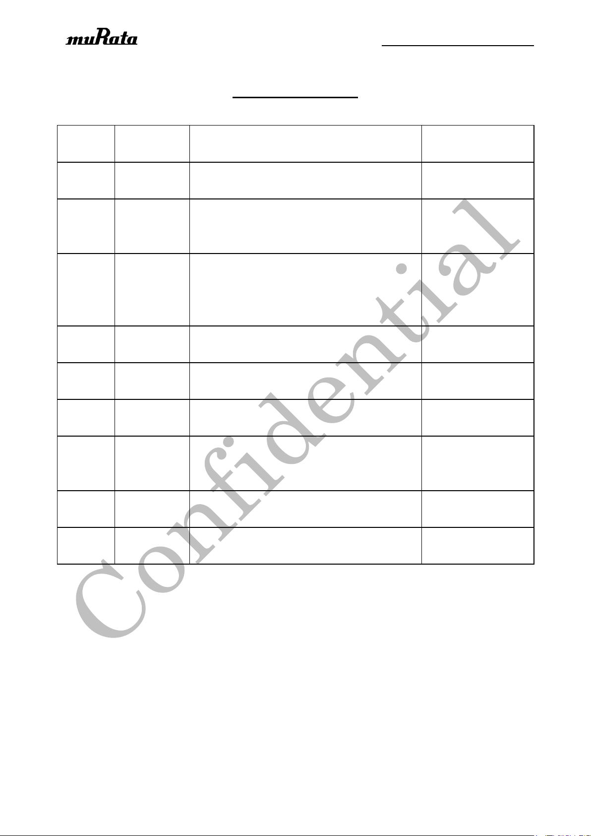
Revision
Code
Date
Description
Comments
0.1
May.14,2013
Initial Draft
TYPE-ABE_Prelimi
nary_20150323
0.2
May.07,2015
-Modify size description, add tolerance information
-Modify Maximum transmitting power from 8dBm
to 5dBm
0.3
July.10,2015
-Modify Operating Voltage from 2V~3.6V to
2.7V~3.6V
-Add information of packing condition and storage
condition
0.4
July.22, 2015
-Add current consumption in Electrical
Characteristics
0.5
Aug.26, 2015
-Modify size information of Customer Board
Design recommendation
0.6
Nov.11, 2015
-Modify pin function of pin17 & pin 18, remove
UART function of these two pins
1.0
Dec.09, 2015
-Add pin description of CC2530 which used to
control internal flash
-Add NC pin description of CC2530
1.1
July.28,2016
-Add Label information
-Add pictures in Packing condition
1.2
Sept. 7, 2017
-Add regulatory statements.
-Revise label info by adding regulatory identifiers.
P. 2/18
Revision History
Page 3

Specification Number : SP-xxxx
P. 3/18
TABLE OF CONTENTS
1. Scope ·························································································································· 4
2. Part Number ·················································································································· 4
3. Dimensions, Marking and Terminal Configurations ·························································· 5
4. Maximum absolute ratings ·························································································· 10
5. Operating Condition ··································································································· 10
6. Electrical Characteristics ····························································································· 10
7. Power Sequences ········································································································ 11
8.1 Power Up/Down Sequence ······················································································ 11
8.2 Reset and Power Cycle Sequence ············································································ 11
8. Packing Condition ······································································································ 12
NOTICE ·························································································································· 13
Page 4
Specification Number : SP-xxxx
Part Number
CMBA1ZZABE
1. Scope
This specification is applied to the IEEE802.15.4 ZigBee Module
- Interface : UART, SPI, PWM
- IC : CC2530 (Texas Instruments)
- Reference Clock: 32MHz reference clock is integrated.
- RoHS : This module is compliant with the RoHS directive.
2. Part Number
P. 4/18
Page 5
Specification Number : SP-xxxx
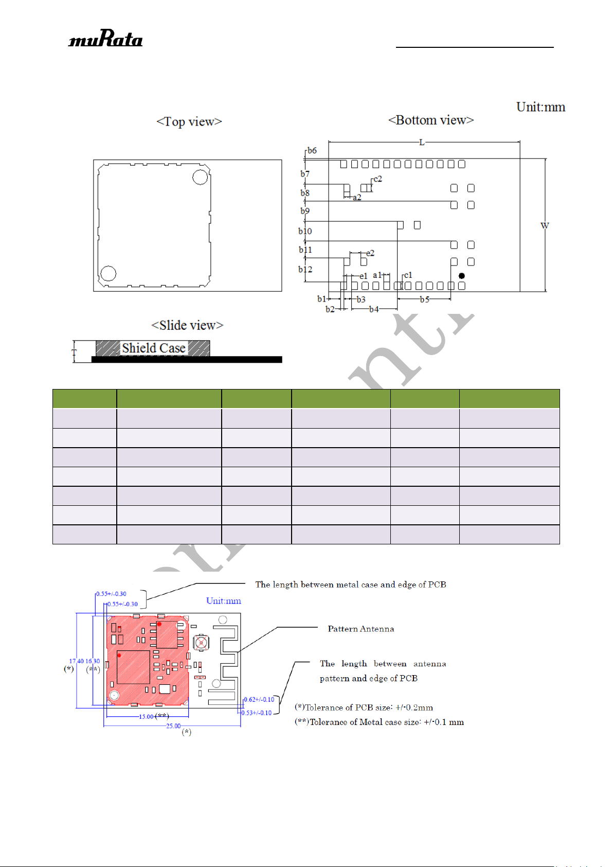
Mark
Dimension
Mark
Dimension
Mark
Dimension
L
25.0±0.2
W
17.4±0.2
T
3.1 max
a1
0.8±0.1
a2
0.8±0.1
b1
1.6±0.15
b2
0.4±0.1
b3
1.0±0.1
b4
6.0±0.1
b5
7.0±0.1
b6
0.25±0.15
b7
3.15±0.1
b8
2.2±0.1
b9
2.6±0.1
b10
2.6±0.1
b11
2.2±0.1
b12
3.15±0.1
c1
1.0±0.1
c2
1.0±0.1
e1
0.6±0.1
e2
1.4±0.1
3. Dimensions, Marking and Terminal Configurations
P. 5/18
Table 1 Dimension (Unit: mm)
Note: This module cannot connect to the external antenna. It has to use the existing antenna (PCB
Antenna).
Page 6
Specification Number : SP-xxxx
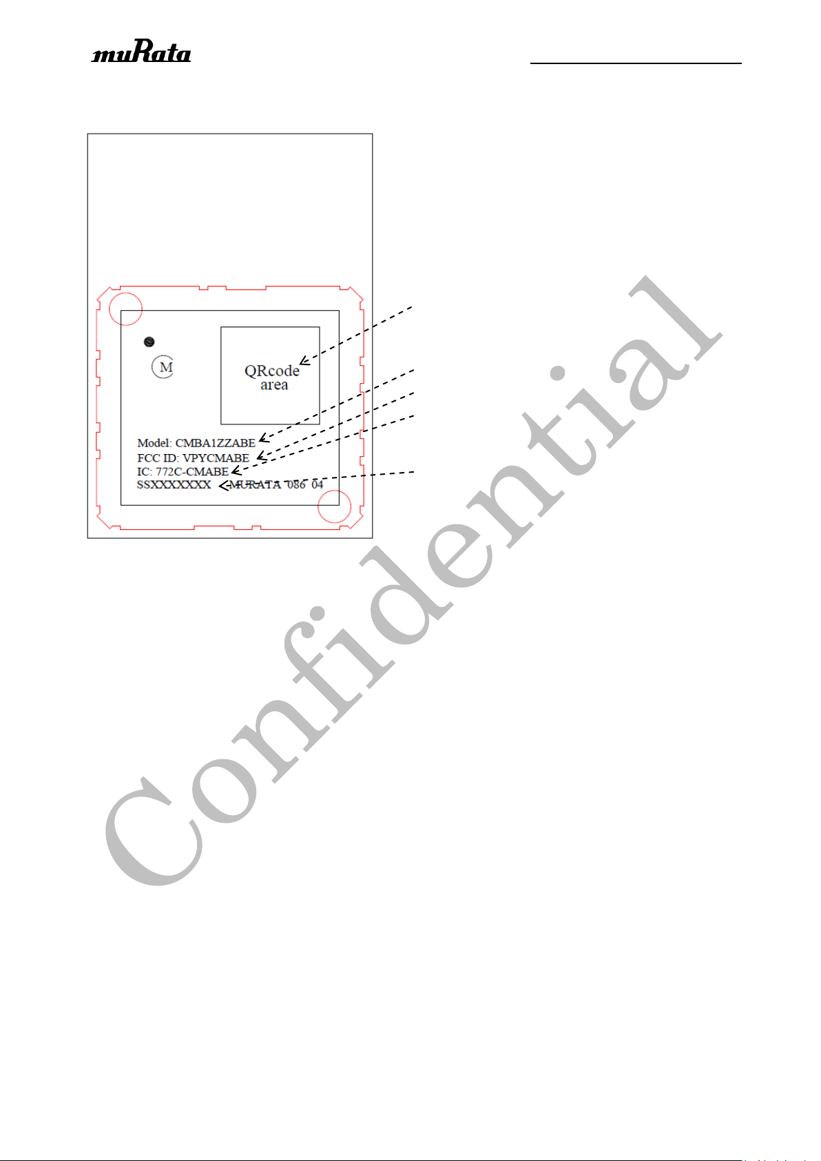
RQ code: for internal use
Model name
FCC ID
IC ID
Inspection number
Label Information
P. 6/18
Page 7
Specification Number : SP-xxxx
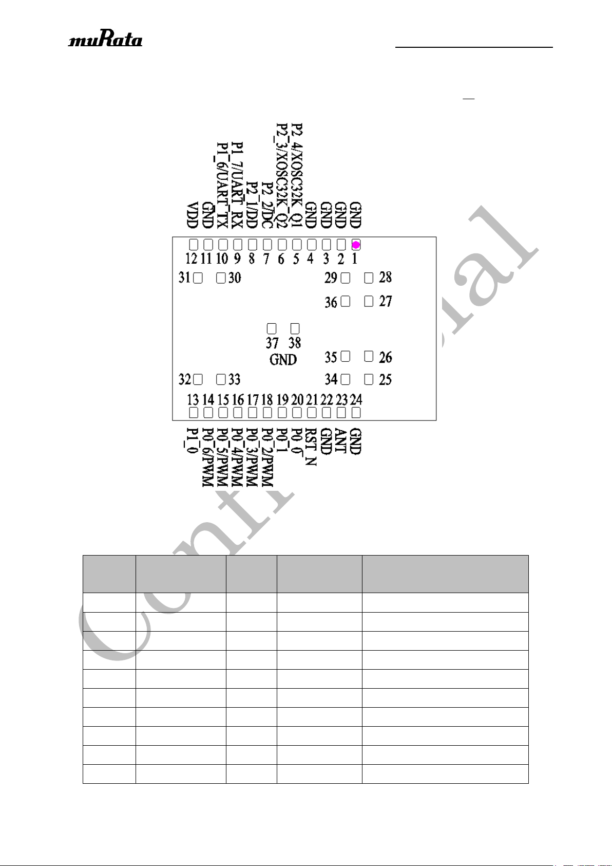
Pin NO.
Terminal Name
Type
Connection to
IC terminal
Description
1
GND
Ground
-
Ground
2
GND
Ground
-
Ground
3
GND
Ground
-
Ground
4
GND
Ground
-
Ground
5
P2_4
I/O
P2_4
Port 2_4/32.768kHz XOSC Q1
6
P2_3
I/O
P2_3
Port 2_3/32.768kHz XOSC Q2
7
P2_2/DC
I/O
P2_2
Port 2_2 or Debug clock
8
P2_1/DD
I/O
P2_1
Port 2_1 or Debug data
9
P1_7/UART_RX
I/O
P1_7
Port 1_7 or UART RX
10
P1_6/UART_TX
I/O
P1_6
Port 1_6 or UART TX
Terminal Configurations
P. 7/18
< Top View >
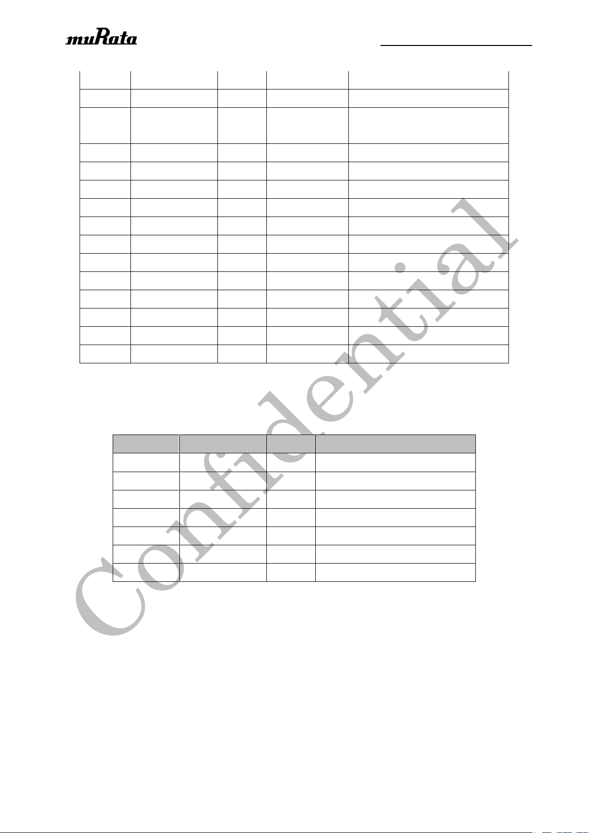
Table 2 Terminal Configurations
Page 8
Specification Number : SP-xxxx
11
GND
Ground
-
Ground
12
VDD
Power
AVDD/DVDD
Power supply
13
P1_0
I/O
P1_0
Port 1_0
20mA drive capability
14
P0_6/PWM
I/O
P0_6
Port 0_6 or PWM
15
P0_5/PWM
I/O
P0_5
Port 0_5 or PWM
16
P0_4/PWM
I/O
P0_4
Port 0_4 or PWM
17
P0_3/PWM
I/O
P0_3
Port 0_3 or PWM
18
P0_2/PWM
I/O
P0_2
Port 0_2 or PWM
19
P0_1
I/O
P0_1
Port 0_1
20
P0_0
I/O
P0_0
Port 0_0
21
RST_N
I
RESET_N
Reset, active-low
22
GND
Ground
-
Ground
23
NC - -
NC
24
GND
Ground
-
Ground
25~ 38
GND
Ground
-
Ground
IC Pin NO.
Terminal Name
Type
Description
5
P1_5/SPI_MOSI
I/O
Used to control internal flash
6
P1_4/SPI_MISO
I/O
Used to control internal flash
7
P1_3/SPI_CLK
I/O
Used to control internal flash
8
P1_2/SPI_SS
I/O
Used to control internal flash
9
P1_1
I/O
Float in module
12
P0_7
I/O
Float in module
36
P2_0
I/O
Float in module
P. 8/18
Note: GPIO pins are to be left OPEN if not used.
Table 2.1 Internal SPI configuration and NC pin
Page 9
Specification Number : SP-xxxx
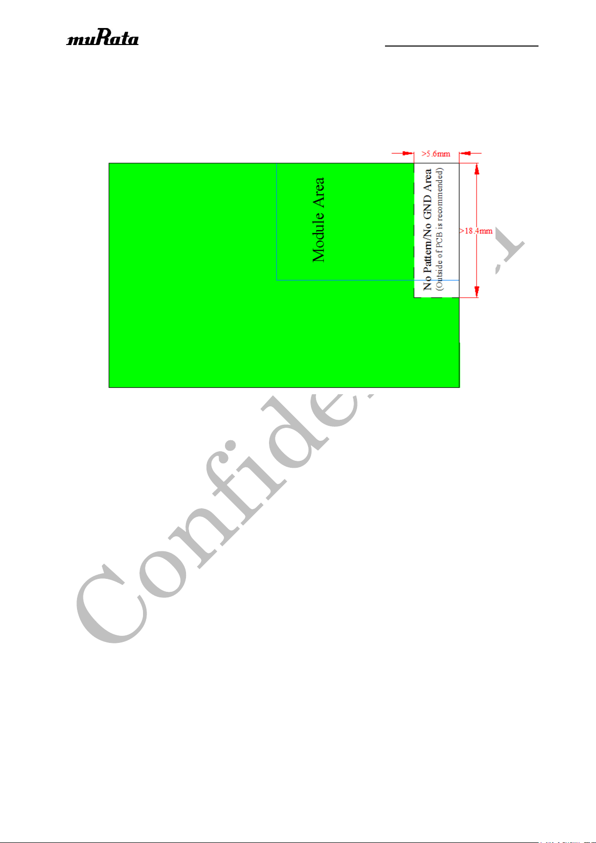
(Reference)
<Customer Board Design recommendation for good RF performance – Top View>
P. 9/18
Page 10
Specification Number : SP-xxxx
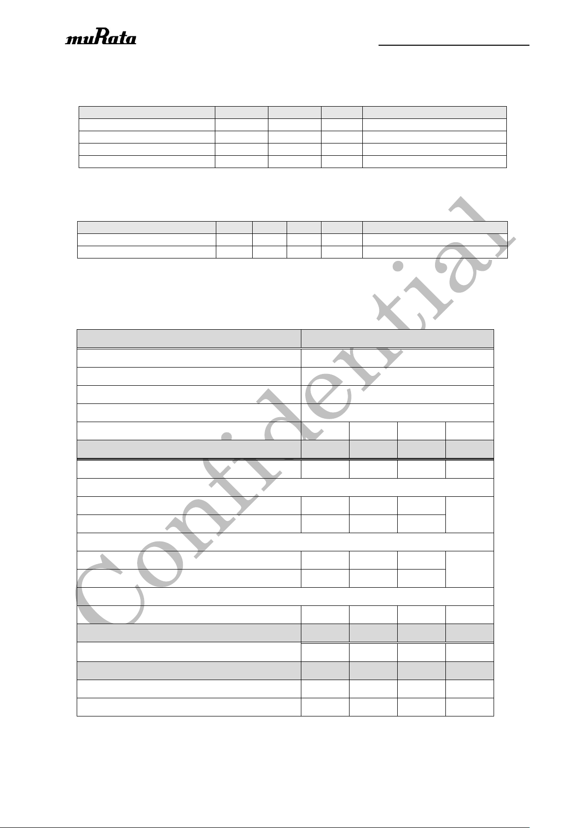
Item
Min
Max
Unit
Remarks
Storage Temperature
-40
+85
degC
VCC
-0.1
3.7
V Voltage on any Digital Pin
-0.1
VCC+0.1
V Input RF Level
10
dBm
Item
Min
Typ
Max
Unit
Remarks
Operating Temperature
-40
25
+85
degC
VCC
2.7
3.3
3.6
V
(Condition: T= +25deg.C, VCC=3.3V and f
c
=2440MHz, measured at antenna feed point.)
Items
Contents
Specification
IEEE 802.15.4
Mode
offset QPSK
Channel frequency (spacing)
2405 to 2480 MHz (5MHz)
Radio baud rate
250kbps
Frequency tolerance
-40 - 40
ppm
Transmitter
Min.
Typ.
Max.
unit
Output power
0
2.5 5 dBm
Spectral density mask (Relative)
f < fc-3.5MHz, RBW:100kHz
-
-47
-20
dBr
f > fc+3.5MHz, RBW:100kHz
-
-44
-20
Spectral density mask (Absolute)
f < fc-3.5MHz, RBW:100kHz
-
-59
-30
dBm
f > fc+3.5MHz, RBW:100kHz
-
-55
-30
EVM
1000 chips, RMS
-
10
35
%
Receiver
Min.
Typ.
Max.
unit
Receiver sensitivity (PER < 1%)
-
-95
-85
dBm
Current Consumption
Min.
Typ.
Max.
unit
Continuous Tx
(1)
-
32 mA
Continuous Rx
(1)
-
25 mA
4. Maximum absolute ratings
Table 3 Maximum ratings
5. Operating Condition
Table 4 Operating specification
6. Electrical Characteristics
Table 5 Electrical specification parameters
P. 10/18
Note(1): Under condition of transmitting or receiving continuous wave
Page 11
Specification Number : SP-xxxx
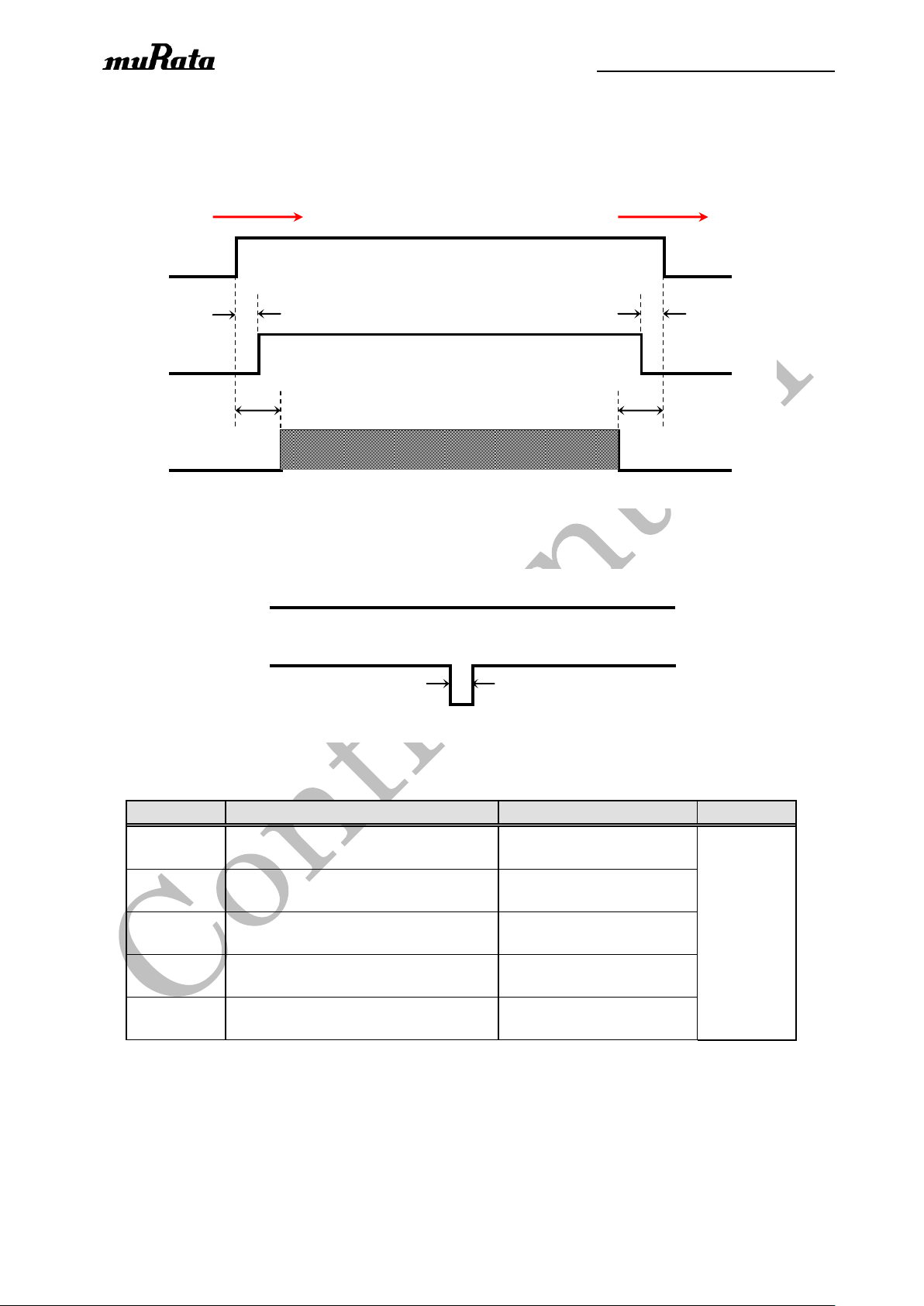
VCC
RST_N
GPIO
TaTbTcTdHLHLH
L
Power Up
Power Down
VCC
RST_N
TeHH
L
Symbol
Description
Typ.
Unit
Ta
Time between VCC valid and
RST_N ramped-up
Ta > 0
usec
Tb
Time between VCC valid
and GPIO enabled
Tb > 400
Tc
Time between RST_N invalid
and VCC invalid
Tc > 0
Td
Time between GPIO invalid
and VCC invalid
Td > 0
Te
Length of RST_N pulse
Te > 1
7. Power Sequences
8.1 Power Up/Down Sequence
8.2 Reset and Power Cycle Sequence
P. 11/18
Page 12
Specification Number : SP-xxxx
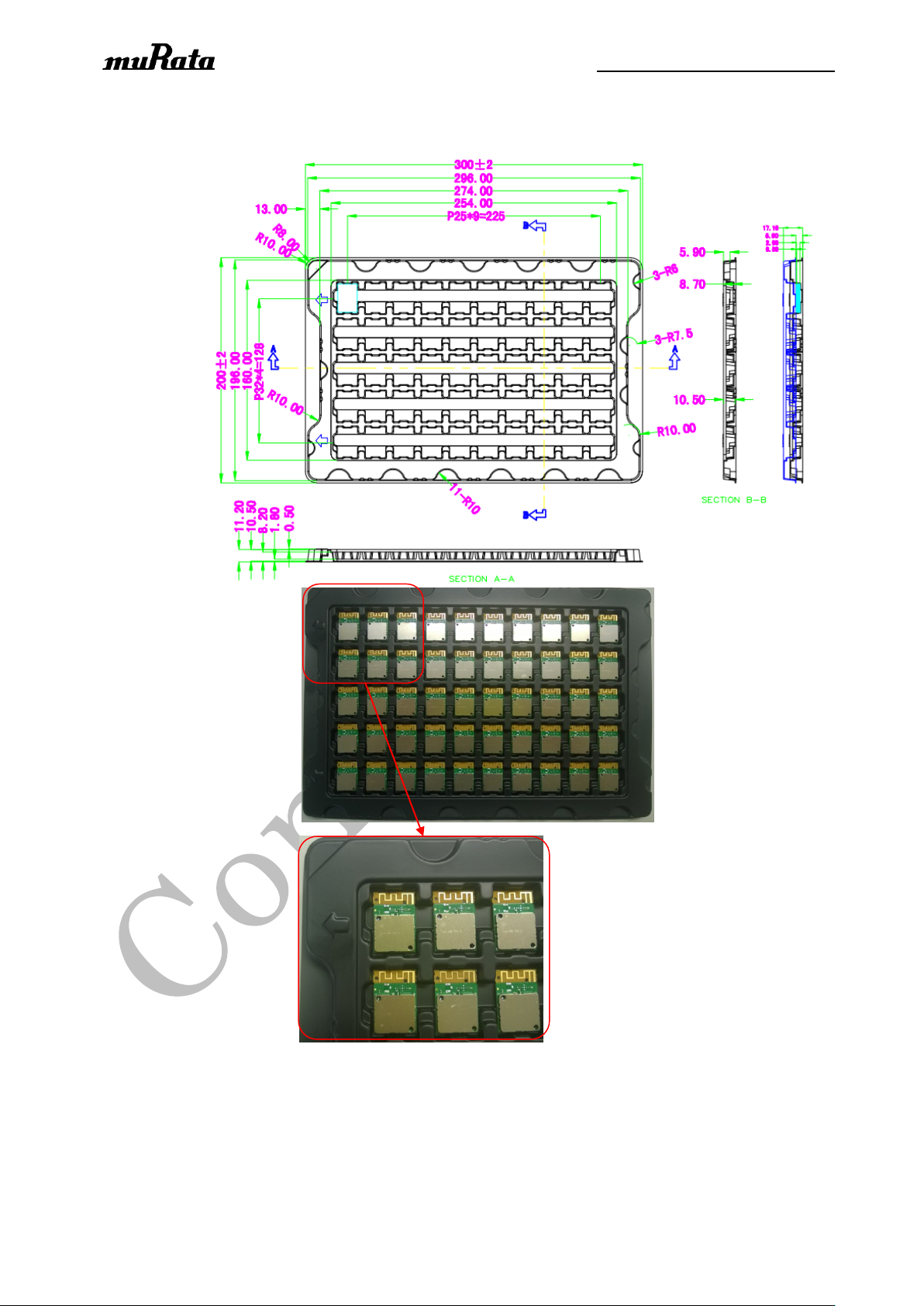
8. Packing Condition
P. 12/18
There are 50pcs of products per tray.
One inner box has nice trays including one tray without products for top. Products quantity of one
inner box is 400pcs. One outer box has four inner boxes. Products quantity of one outer box is
1600pcs.
Page 13

Specification Number : SP-xxxx
NOTICE
1 Storage Conditions:
Please use this product within 6 months after receipt.
The product shall be stored without opening the packing under the ambient temperature
from 5 to 35 °C and humidity from 20 to 70 %RH. (Packing materials, in particular, may be
deformed at the temperature over 40 °C)
The product shall be stored in non-corrosive gas (Cl2, NH3, SO2, NOx, etc.).
Any excess mechanical shock including, but not limited to, sticking the packing materials by
sharp object and dropping the product, shall not be applied in order not to damage the
packing materials.
This product is applicable to MSL3 (Based on JEDEC Standard J-STD-020)
P. 13/18
After the packing opened, the product shall be stored at <30deg.C / <60%RH and the product
shall be used within 168hours.
When the color of the indicator in the packing changed, the product shall be baked before
soldering.
Baking condition : 125 +5/-0deg.C, 24hours, 1time
The products shall be baked on the heat-resistant tray because the material (Base Tape, Reel Tape
and Cover Tape) are not heat-resistant.
2 Handling Conditions :
Be careful in handling or transporting products because excessive stress or mechanical shock may
break products.
Handle with care if products may have cracks or damages on their terminals, the characteristics of
products may change. Do not touch products with bear hands that may result in poor solderability and
destroy by static electrical charge.
Page 14

Specification Number : SP-xxxx
P. 14/18
3 Standard PCB Design (Land Pattern and Dimensions) :
All the ground terminals should be connected to the ground patterns. Furthermore, the ground pattern
should be provided between IN and OUT terminals. Please refer to the specifications for the standard
land dimensions.
The recommended land pattern and dimensions is as Murata's standard. The characteristics of
products may vary depending on the pattern drawing method, grounding method, land dimensions,
land forming method of the NC terminals and the PCB material and thickness. Therefore, be sure to
verify the characteristics in the actual set. When using non-standard lands, contact Murata
beforehand.
4 Notice for Chip Placer :
When placing products on the PCB, products may be stressed and broken by uneven forces from a
worn-out chucking locating claw or a suction nozzle. To prevent products from damages, be sure to
follow the specifications for the maintenance of the chip placer being used. For the positioning of
products on the PCB, be aware that mechanical chucking may damage products.
Page 15
Specification Number : SP-xxxx
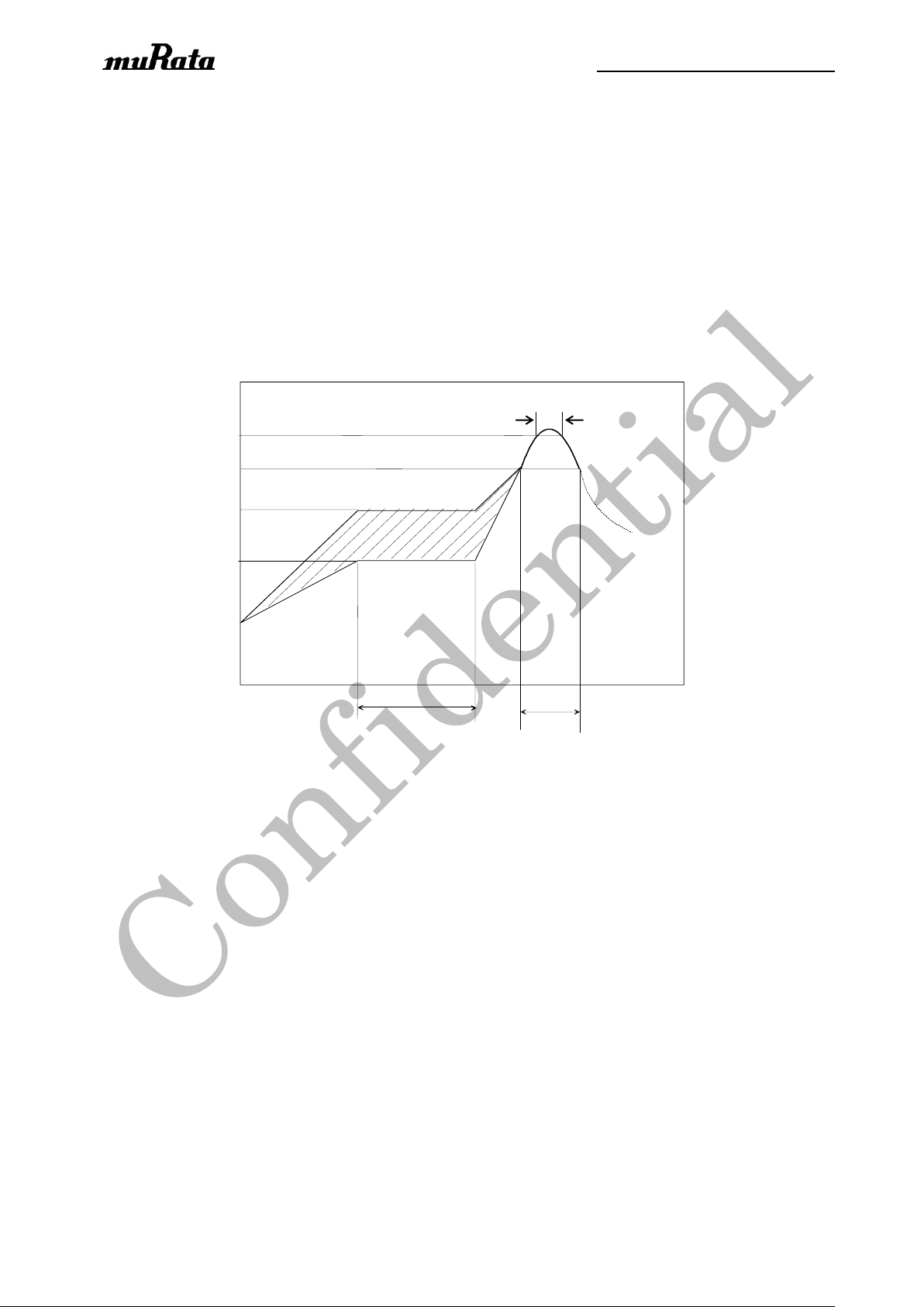
Within 120s
Pre-heating
time(s)
Within 60s
Cooling down
Slowly
180 deg.C
150 deg.C
240 to 250 deg.C
Within 3s
P. 15/18
5 Soldering Conditions :
The recommendation conditions of soldering are as in the following figure.
When products are immersed in solvent after mounting, pay special attention to maintain the temperature
difference within 100 °C. Soldering must be carried out by the above mentioned conditions to prevent
products from damage. Set up the highest temperature of reflow within 260 ℃.
Contact Murata before use if concerning other soldering conditions.
Reflow soldering standard conditions(Example)
Please use the reflow within 2 times.
Use rosin type flux or weakly active flux with a chlorine content of 0.2 wt % or less.
6 Cleaning:
Since this Product is Moisture Sensitive, any cleaning is not permitted.
Page 16

Specification Number : SP-xxxx
P. 16/18
7 Operational Environment Conditions:
Products are designed to work for electronic products under normal environmental conditions
(ambient temperature, humidity and pressure). Therefore, products have no problems to be used
under the similar conditions to the above-mentioned. However, if products are used under the
following circumstances, it may damage products and leakage of electricity and abnormal temperature
may occur.
- In an atmosphere containing corrosive gas ( Cl2, NH3, SOx, NO
- In an atmosphere containing combustible and volatile gases.
- Dusty place.
- Direct sunlight place.
- Water splashing place.
- Humid place where water condenses.
- Freezing place.
If there are possibilities for products to be used under the preceding clause, consult with Murata before
actual use.
As it might be a cause of degradation or destruction to apply static electricity to products, do not apply
static electricity or excessive voltage while assembling and measuring.
x
etc.).
8 Input Power Capacity:
Products shall be used in the input power capacity as specified in this specifications.
Inform Murata beforehand, in case that the components are used beyond such input power capacity
range.
9 FCC/Industry Canada Statement (to be placed on End Products)
FCC statement:
This module has been tested and found to comply with the FCC Part15.
These limits are designed to provide reasonable protection against harmful interference in approved
installations.
Note: This equipment has been tested and found to comply with the limits for a Class B digital device,
pursuant to part 15 of the FCC Rules. These limits are designed to provide reasonable protection
against harmful interference in a residential installation. This equipment generates, uses and can
radiate radio frequency energy and, if not installed and used in accordance with the instructions, may
Page 17

Specification Number : SP-xxxx
P. 17/18
cause harmful interference to radio communications. However, there is no guarantee that interference
will not occur in a particular installation. If this equipment does cause harmful interference to radio or
television reception, which can be determined by turning the equipment off and on, the user is
encouraged to try to correct the interference by one or more of the following measures:
—Reorient or relocate the receiving antenna.
—Increase the separation between the equipment and receiver.
—Connect the equipment into an outlet on a circuit different from that to which the receiver is
connected.
—Consult the dealer or an experienced radio/TV technician for help.
This device complies with part 15 of the FCC Rules. Operation is subject to the following two
conditions: (1) This device may not cause harmful interference, and (2) this device must accept any
interference received, including interference that may cause undesired operation.
Modifications or changes to this equipment not expressly approved by Murata Manufacturing Co., Ltd.
may void the user’s authority to operate this equipment.
The modular transmitter must be equipped with either a permanently affixed label or must be capable
of electronically displaying its FCC identification number
(A) If using a permanently affixed label, the modular transmitter must be labeled with its own FCC
identification number, and, if the FCC identification number is not visible when the module is installed
inside another device, then the outside of the device into which the module is installed must also
display a label referring to the enclosed module. This exterior label can use wording such as the
following: “Contains Transmitter Module FCC ID: VPYCMABE” or “Contains FCC ID: VPYCMABE.”
(B) If the modular transmitter uses an electronic display of the FCC identification number, the
information must be readily accessible and visible on the modular transmitter or on the device in which
it is installed. If the module is installed inside another device, then the outside of the device into which
the module is installed must display a label referring to the enclosed module. This exterior label can
use wording such as the following: “Contains FCC certified transmitter module(s).”
To satisfy FCC RF Exposure requirements for mobile and base station transmission devices, a
separation distance of 20 cm or more should be maintained between the antenna of this device and
persons during operation. To ensure compliance, operation at closer than this distance is not
recommended. The antenna(s) used for this transmitter must not be co-located or operating in
conjunction with any other antenna or transmitter.
IC statement:
Label of the end product:
The final end product must be labeled in a visible area with the following "Contains transmitter module
Page 18

Specification Number : SP-xxxx
IC: 772C-CMABE"
This Class B digital apparatus complies with Canadian ICES-003.
Cetappareilnumérique de la classe B estconforme à la norme NMB-003 du Canada.
This device complies with Industry Canada’s license-exempt RSSs. Operation is subject to the
following two conditions:
(1) This device may not cause interference; and
(2) This device must accept any interference, including interference that may cause undesired
operation of the device.
Le présent appareil est conforme aux CNR d’Industrie Canada applicables aux appareils radio
exempts de licence. L’exploitation est autorisée aux deux conditions suivantes :
1) l’appareil ne doit pas produire de brouillage;
P. 18/18
2) l’appareil doit accepter tout brouillage radioélectrique subi, même si le brouillage est susceptible
d’en compromettre le fonctionnement.
Radiation Exposure Statement:
This equipment complies with IC radiation exposure limits set forth for an uncontrolled environment.
This equipment should be installed and operated with minimum distance 20cm between the radiator &
your body.
Déclaration d'exposition aux radiations:
Cet équipement est conforme aux limites d'exposition aux rayonnements IC établies pour un
environnement non contrôlé. Cet équipement doit être installé et utilisé avec un minimum de 20cm de
distance entre la source de rayonnement et votre corps.
Notice to OEM integrator
The end user manual shall include all required regulatory information/warning as show in this manual.
The OEM integrator is responsible for testing their end‐product for any additional compliance
requirements required with this module installed.
If the FCC ID is not visible when the module is installed inside another device, then the outside of the
device into which the module is installed must also
display a label referring to the enclosed module. The end product shall haves the words “Contains
Transmitter Module FCC ID: VPYCMABE, IC: 772C-CMABE”.
 Loading...