


OPERATION AND PARTS MANUAL
WHISPERWATT™ SERIES
MODEL DCA150USJ3CAN
60HZ GENERATOR
(JOHN DEERE 6068HF285 DIESEL ENGINE)
PARTS LIST NO. M3874400114
Revision #1 (05/19/15)
To find the latest revision of this
publication, visit our website at:
www.multiquip.com
THIS MANUAL MUST ACCOMPANY THE EQUIPMENT AT ALL TIMES.

FUEL AND CHEMICAL EXPOSURE WARNINGS
Diesel engine exhaust and some of
its constituents are know to cause
cancer, birth defects and other
reproductive harm.
PAGE 2 — DCA150USJ3CAN 60 HZ GENERATOR • OPERATION AND PARTS MANUAL — REV. #1 (05/19/15)

REPORTING SAFETY DEFECTS
If you believe that your vehicle has a defect that could cause a crash or could
cause injury or death, you should immediately inform the National Highway
Traffi c Safety Administration (NHTSA) in addition to notifying Multiquip Inc. at
1-800-421-1244.
If NHTSA receives similar complaints, it may open an investigation, and if it
fi nds that a safety defect exists in a group of vehicles, it may order a recall and
remedy campaign. However, NHTSA cannot become involved in individual
problems between you, your dealer, or Multiquip Inc.
To contact NHTSA, you may either call the Vehicle Safety Hotline toll-free
at 1-888-327-4236 (TTY: 1-800-424-9153), go to http://www.safercar.gov; or
write to:
Administrator
NHTSA
400 Seventh Street, SW.,
Washington, DC 20590
You can also obtain information about motor vehicle safety from
http://www.safercar.gov.
DCA150USJ3CAN 60 HZ GENERATOR • OPERATION AND PARTS MANUAL — REV. #1 (05/19/15) — PAGE 3

TABLE OF CONTENTS
DCA150USJ3CAN 60 HzGenerator
Fuel And Chemical Exposure Warnings .................. 2
Reporting Safety Defects ......................................... 3
Table Of Contents .................................................... 4
Parts Ordering Procedures ...................................... 5
Safety Information .............................................. 6-11
Specifications ........................................................ 12
Dimensions ............................................................ 13
Installation ........................................................ 14-15
General Information ............................................... 16
Major Components ................................................ 17
Diagnostic Display ............................................ 18-34
Generator Control Panel ........................................ 35
Engine Operating Panel....................................36-37
Output Terminal Panel Familiarization .............. 38-40
Load Application .................................................... 41
Generator Outputs ................................................. 42
Generator Outputs/Gauge Reading ....................... 43
Output Terminal Panel Connections ................. 44-45
3Ø 600 Vac Auto Transformer Connections ........... 46
Inspection/Setup ............................................... 47-50
Generator Start-Up Procedure ........................ 51-52
Generator Shut-Down Procedures ........................ 53
Maintenance ..................................................... 54-57
Trailer Maintenance .......................................... 58-62
Trailer Wiring Diagram ........................................... 63
Generator Wiring Diagram ..................................... 64
3Ø 600 VAC Auto Transformer Wiring Diagram ..... 65
Engine Wiring Diagram .......................................... 66
Battery Charger Wiring Diagram ........................... 67
Heater Element Wiring Diagram ............................ 68
Troubleshooting (Generator) .................................. 69
Troubleshooting (Engine Controller) ...................... 70
Explanation of Code in Remarks Column.............. 72
Suggested Spare Parts ......................................... 73
Component Drawings
Generator Assembly ......................................... 74-75
Control Box Assembly ......................................76-79
Engine And Radiator Assembly ........................ 80-83
Output Terminal Assembly ................................ 84-87
Battery Assembly.............................................. 88-89
Muffler Assembly .............................................. 90-91
Fuel Tank Assembly .......................................... 92-93
Enclosure (1) Assembly .................................... 94-97
Enclosure (2) Assembly .................................. 98-101
Rubber Seals Assembly. ............................... 102-103
Battery Charger Assembly (Option) ............ 104-105
3Ø 600 Vac Transformer Assembly (Option) 106-07
Heating Element Assembly (Option) .......... 108-109
Nameplate And Decals Assembly ............... 110-115
Terms And Conditions Of Sale — Parts .............. 116
NOTICE
Specifications are subject to change without notice.
PAGE 4 — DCA150USJ3CAN 60 HZ GENERATOR • OPERATION AND PARTS MANUAL — REV. #1 (05/19/15)

PARTS ORDERING PROCEDURES
www.multiquip.com
Ordering parts has never been easier!
If you have an MQ Account, to obtain a Username
parts@multiquip.
To obtain an MQ Account, contact your
Effective:
, 2006
Choose from three easy options:
January 1
st
Best Deal!
Order via Internet (Dealers Only):
Order parts on-line using Multiquip’s SmartEquip website!
■ View Parts Diagrams
■ Order Parts
■ Print Specification Information
Goto www.multiquip.com and click on
Order Parts
to log in and save!
Order via Fax (Dealers Only):
All customers are welcome to order parts via Fax.
Domestic (US) Customers dial:
1-800-6-PARTS-7 (800-672-7877)
Order via Phone:
Non-Dealer Customers:
Contact your local Multiquip Dealer for
parts or call 800-427-1244 for help in
locating a dealer near you.
and Password, E-mail us at:
com.
District Sales Manager for more information.
Use the internet and qualify for a 5% Discount
on Standard orders for all orders which include
complete part numbers.*
Fax your order in and qualify for a 2% Discount
on Standard orders for all orders which include
complete part numbers.*
Domestic (US) Dealers Call:
1-800-427-1244
International Customers should contact
their local Multiquip Representatives for
Parts Ordering information.
Note: Discounts Are Subject To Change
Note: Discounts Are Subject To Change
DCA150USJ3CAN 60 HZ GENERATOR • OPERATION AND PARTS MANUAL — REV. #1 (05/19/15) — PAGE 5
When ordering parts, please supply:
❒ Dealer Account Number
❒ Dealer Name and Address
❒ Shipping Address (if different than billing address)
❒ Return Fax Number
❒ Applicable Model Number
❒ Quantity, Part Number and Description of Each Part
NOTICE
All orders are treated as Standard Orders and will
ship the same day if received prior to 3PM PST.
WE ACCEPT ALL MAJOR CREDIT CARDS!
❒ Specify Preferred Method of Shipment:
✓ UPS/Fed Ex ✓ DHL
■ Priority One ✓ Tr uck
■ Ground
■ Next Day
■ Second/Third Day
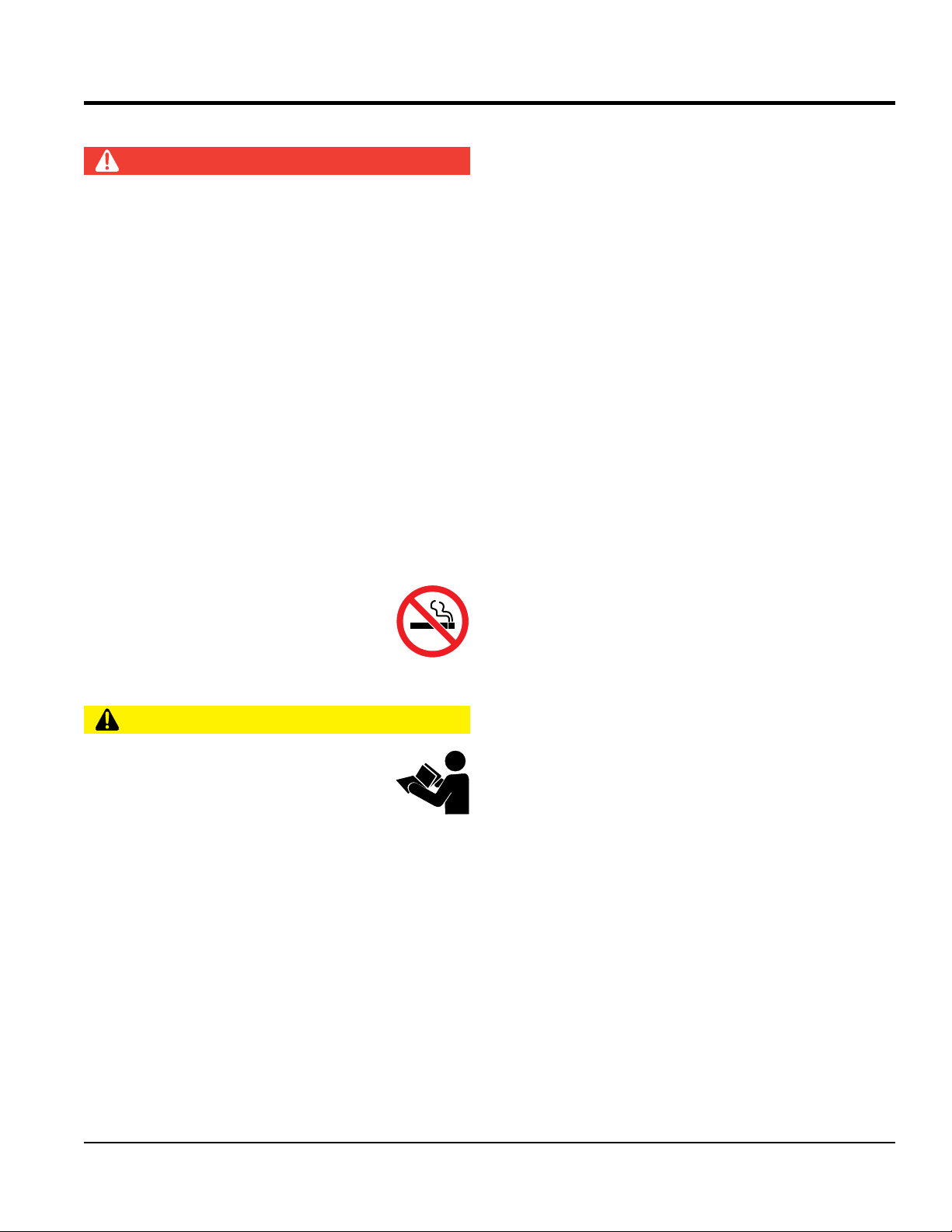
SAFETY INFORMATION
Do not operate or service the equipment before reading the
entire manual. Safety precautions should be followed at all
times when operating this equipment. Failure to read and
understand the safety messages and operating instructions
could result in injury to yourself and others.
SAFETY MESSAGES
The four safety messages shown below will inform you
about potential hazards that could injure you or others. The
safety messages specifi cally address the level of exposure
to the operator and are preceded by one of four words:
DANGER, WARNING, CAUTION
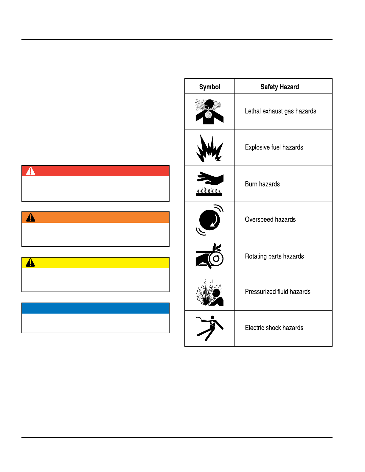
SAFETY SYMBOLS
Potential hazards associated with the operation of this
equipment will be referenced with hazard symbols which
may appear throughout this manual in conjunction with
safety messages.
DANGER
Indicates a hazardous situation which, if not avoided,
WILL result in DEATH or SERIOUS INJURY.
WARNING
Indicates a hazardous situation which, if not avoided,
COULD result in DEATH or SERIOUS INJURY.
or NOTICE.
CAUTION
Indicates a hazardous situation which, if not avoided,
COULD result in MINOR or MODERATE INJURY.
NOTICE
Addresses practices not related to personal injury.
PAGE 6 — DCA150USJ3CAN 60 HZ GENERATOR • OPERATION AND PARTS MANUAL — REV. #1 (05/19/15)
SAFETY INFORMATION
GENERAL SAFETY
NEVER use accessories or attachments that are not
recommended by MQ Power for this equipment. Damage
Also, know the
and
This information will be invaluable in
emergency or safety devices.
These devices are intended for operator safety.
Disconnection of these devices can cause severe injury,
bodily harm or even death. Disconnection of any of these
lubricate components or attempt service on a
Fix damage to machine and replace any broken parts
store equipment properly when it is not being
used. Equipment should be stored in a clean, dry location
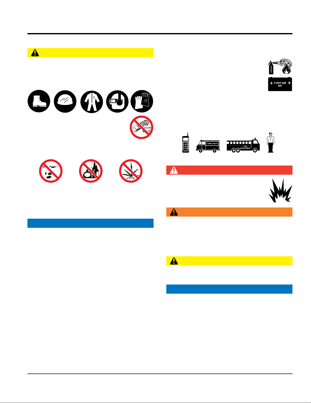
CAUTION
NEVER operate this equipment without proper protective
clothing, shatterproof glasses, respiratory protection,
hearing protection, steel-toed boots and other protective
devices required by the job or city and state regulations.
NEVER operate this equipment when not
feeling well due to fatigue, illness or when
under medication.
NEVER operate this equipment under the infl uence of
drugs or alcohol.
ALWAYS check the equipment for loosened threads or
bolts before starting.
DO NOT use the equipment for any purpose other than
its intended purposes or applications.
to the equipment and/or injury to user may result.
ALWAYS know the location of the nearest
fi re extinguisher.
ALWAYS know the location of the nearest
fi rst aid kit.
ALWAYS know the location of the nearest
phone or keep a phone on the job site.
phone numbers of the nearest ambulance, doctor
fi re department.
the case of an emergency.
GENERATOR SAFETY
DANGER
NEVER operate the equipment in an explosive
atmosphere or near combustible materials. An
explosion or fi re could result causing severe
bodily harm or even death.
WARNING
NOTICE
This equipment should only be operated by trained and
qualifi ed personnel 18 years of age and older.
Whenever necessary, replace nameplate, operation and
safety decals when they become diffi cult read.
Manufacturer does not assume responsibility for any
accident due to equipment modifi cations. Unauthorized
equipment modifi cation will void all warranties.
NEVER disconnect any
devices will void all warranties.
CAUTION
NEVER
running machine.
NOTICE
ALWAYS ensure generator is on level ground before use.
ALWAYS keep the machine in proper running condition.
immediately.
ALWAYS
out of the reach of children and unauthorized personnel
DCA150USJ3CAN 60 HZ GENERATOR • OPERATION AND PARTS MANUAL — REV. #1 (05/19/15) — PAGE 7
ENGINE SAFETY
NOTICE
run engine without an air fi lter or with a dirty air
fi lter. Severe engine damage may occur. Service air fi lter
Wet stacking is a common problem with diesel engines
which are operated for extended periods with light or
no load applied. When a diesel engine operates without
suffi cient load (less than 40% of the rated output), it will
not operate at its optimum temperature. This will allow
unburned fuel to accumulate in the exhaust system,
which can foul the fuel injectors, engine valves and
exhaust system, including turbochargers, and reduce
it must be able to provide fuel and air in the proper ratio
and at a high enough engine temperature for the engine
Wet stacking does not usually cause any permanent
damage and can be alleviated if additional load is
applied to relieve the condition. It can reduce the system
performance and increase maintenance. Applying an
increasing load over a period of time until the excess
fuel is burned off and the system capacity is reached
usually can repair the condition. This can take several
State Health Safety Codes and Public Resources
Codes specify that in certain locations, spark arresters
must be used on internal combustion engines that use
hydrocarbon fuels. A spark arrester is a device designed
to prevent accidental discharge of sparks or fl ames
from the engine exhaust. Spark arresters are qualifi ed
and rated by the United States Forest Service for this
purpose. In order to comply with local laws regarding
spark arresters, consult the engine distributor or the
SAFETY INFORMATION
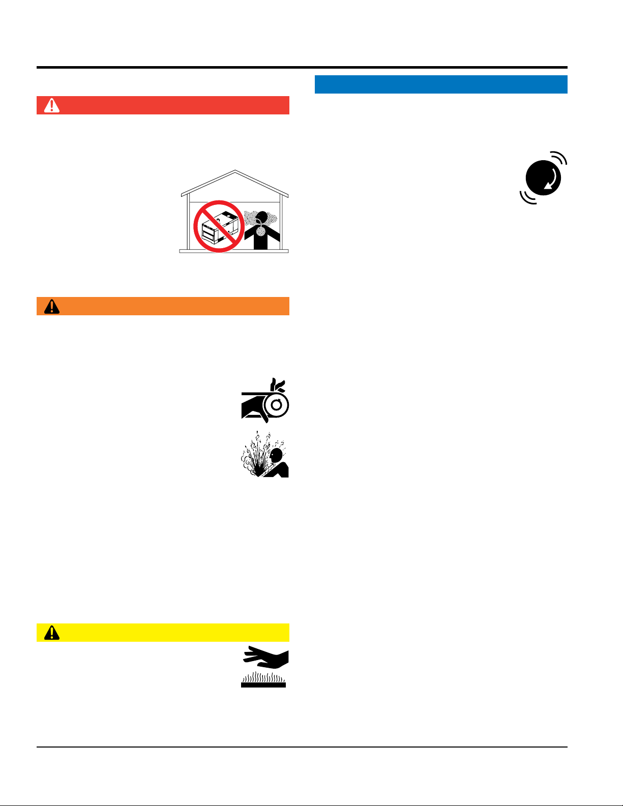
DANGER
The engine fuel exhaust gases contain poisonous carbon
monoxide. This gas is colorless and odorless, and can
cause death if inhaled.
The engine of this equipment
requires an adequate free
fl ow of cooling air. NEVER
operate this equipment in
any enclosed or narrow area
where free fl ow of the air is
restricted. If the air fl ow is
restricted it will cause injury to people and property and
serious damage to the equipment or engine.
WARNING
DO NOT place hands or fingers inside engine
compartment when engine is running.
NEVER operate the engine with heat shields or
guards removed.
Keep fi ngers, hands hair and clothing away
from all moving parts to prevent injury.
NEVER
frequently to prevent engine malfunction.
NEVER tamper with the factory settings
of the engine or engine governor. Damage
to the engine or equipment can result
if operating in speed ranges above the
maximum allowable.
the operating performance.
In order for a diesel engine to operate at peak effi ciency,
to completely burn all of the fuel.
DO NOT remove the radiator cap while the
engine is hot. High pressure boiling water
will gush out of the radiator and severely
scald any persons in the general area of
the generator.
DO NOT remove the coolant drain plug while the engine
is hot. Hot coolant will gush out of the coolant tank and
severely scald any persons in the general area of the
generator.
DO NOT remove the engine oil drain plug while the
engine is hot. Hot oil will gush out of the oil tank and
severely scald any persons in the general area of the
generator.
CAUTION
NEVER touch the hot exhaust manifold,
muffl er or cylinder. Allow these parts to cool
before servicing equipment.
hours to burn off the accumulated unburned fuel.
local Health and Safety Administrator.
PAGE 8 — DCA150USJ3CAN 60 HZ GENERATOR • OPERATION AND PARTS MANUAL — REV. #1 (05/19/15)
SAFETY INFORMATION
FUEL SAFETY
TOWING SAFETY
Make sure the hitch and coupling of the towing vehicle
are rated equal to, or greater than the trailer “gross
NEVER
Check the tire air pressure on both towing vehicle and
Trailer tires should be infl ated to 50 psi cold.
safety
attach trailer’s safety chains to towing
make sure the vehicle and trailer directional,
backup, brake and trailer lights are connected and
• Secure portable power cables in cable tray with tie
unless
posted otherwise. Recommended off-road towing is not to
Avoid sudden stops and starts. This can cause skidding,
or jack-knifi ng. Smooth, gradual starts and stops will
Trailer should be adjusted to a level position at all times
Raise and lock trailer wheel stand in up position when
rolling
underneath the trailer’s bumper
Use the trailer’s swivel jack to adjust the trailer height to
DANGER
DO NOT start the engine near spilled fuel or combustible
fl uids. Diesel fuel is extremely fl ammable and its vapors
can cause an explosion if ignited.
ALWAYS refuel in a well-ventilated area, away from
sparks and open fl ames.
ALWAYS use extreme caution when working with
fl ammable liquids.
DO NOT fi ll the fuel tank while the engine is running
or hot.
DO NOT overfi ll tank, since spilled fuel could ignite if it
comes into contact with hot engine parts or sparks from
the ignition system.
Store fuel in appropriate containers, in well-ventilated
areas and away from sparks and fl ames.
NEVER use fuel as a cleaning agent.
DO NOT smoke around or near the
equipment. Fire or explosion could result
from fuel vapors or if fuel is spilled on a
hot engine.
CAUTION
Check with your local county or state safety
towing regulations, in addition to meeting
Department of Transportation (DOT)
Safety Towing Regulations, before towing
your generator.
Refer to MQ Power trailer manual for additional safety
information.
In order to reduce the possibility of an accident while
transporting the generator on public roads, ALWAYS
make sure the trailer that supports the generator and
the towing vehicle are mechanically sound and in good
operating condition.
ALWAYS shutdown engine before transporting
vehicle weight rating.”
ALWAYS inspect the hitch and coupling for wear.
tow a trailer with defective hitches, couplings, chains, etc.
trailer.
Also check the tire tread wear on both vehicles.
ALWAYS make sure the trailer is equipped with a
chain.
ALWAYS properly
vehicle.
ALWAYS
working properly.
DOT Requirements include the following:
• Connect and test electric brake operation.
wraps.
The maximum speed for highway towing is 55 MPH
exceed 15 MPH or less depending on type of terrain.
improve towing.
Avoid sharp turns to prevent rolling.
when towing.
towing.
Place chock blocks underneath wheel to prevent
while parked.
Place support blocks
to prevent tipping while parked.
a level position while parked.
DCA150USJ3CAN 60 HZ GENERATOR • OPERATION AND PARTS MANUAL — REV. #1 (05/19/15) — PAGE 9
ELECTRICAL SAFETY
DANGER
Power Cord/Cable Safety
Make sure power cables are securely connected to the
generator’s output receptacles. Incorrect connections
may cause electrical shock and damage to the
make certain that proper power or extension
cord has been selected for the job. See Cable Selection
make sure that electrical circuits are properly
grounded to a suitable earth ground (ground rod) per
the National Electrical Code (NEC) and local codes
Severe injury or death by
can result from operating an ungrounded
drop the battery. There is a possibility that the
keep the battery charged. If the battery is not
recharge the battery in a well-ventilated
environment to avoid the risk of a dangerous concentration
DO NOT touch output terminals during
operation. Contact with output terminals
during operation can cause electrocution,
electrical shock or burn.
The electrical voltage required to
operate the generator can cause severe
injury or even death through physical contact with live
circuits. Turn generator and all circuit breakers OFF
before performing maintenance on the generator or
making contact with output terminals.
NEVER insert any objects into the output
receptacles during operation. This is
extremely dangerous. The possibility exists
of electrical shock, electrocution or
death.
Backfeed to a utility system can cause
electrocution and/or property damage.
NEVER connect the generator to a
building’s electrical system without
a transfer switch or other approved
device. All installations should be
performed by a licensed electrician in accordance with
all applicable laws and electrical codes. Failure to do so
could result in electrical shock or burn, causing serious
injury or even death.
SAFETY INFORMATION
generator.
NOTICE
ALWAYS
Chart in this manual.
Grounding Safety
DANGER
ALWAYS
before operating generator.
electrocution
generator.
NEVER use gas piping as an electrical ground.
BATTERY SAFETY
DANGER
DO NOT
battery will explode.
DO NOT expose the battery to open fl ames,
sparks, cigarettes, etc. The battery contains
combustible gases and liquids. If these
gases and liquids come into contact with a
fl ame or spark, an explosion could occur.
DANGER
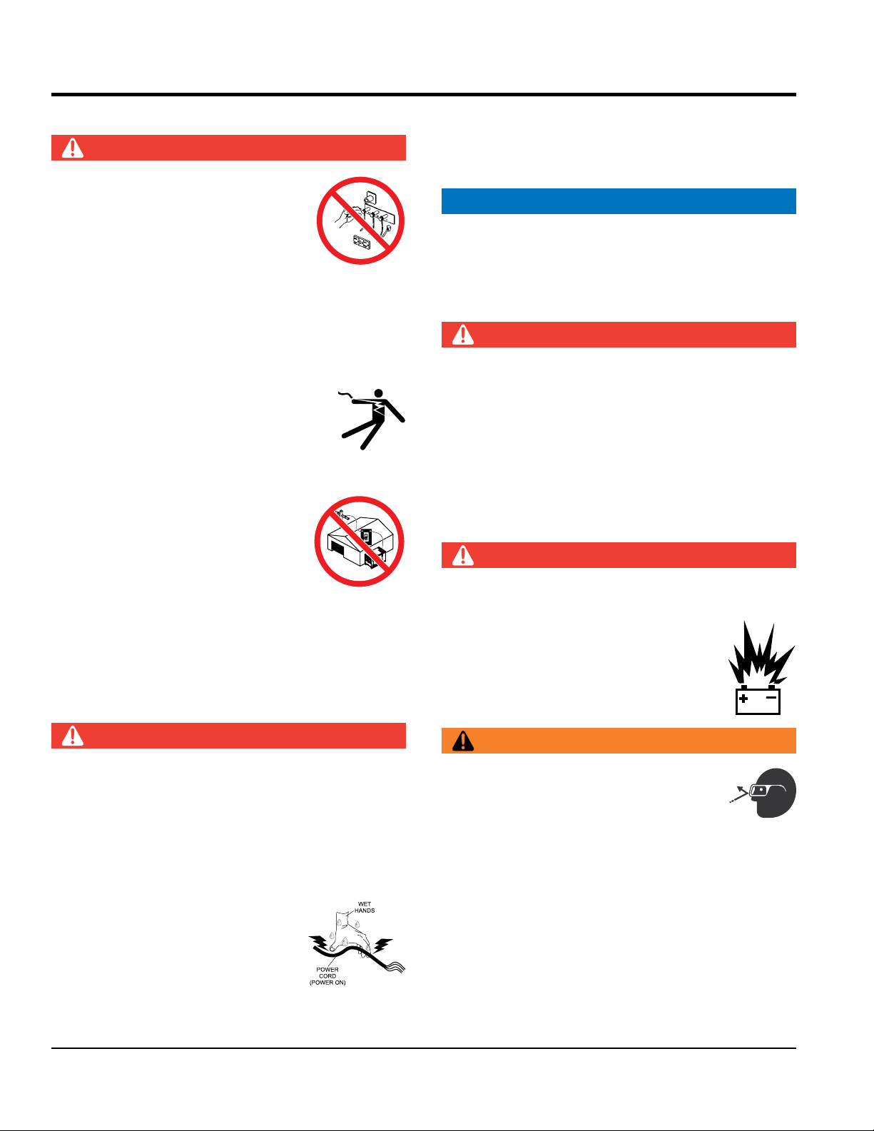
NEVER let power cords or cables lay in water.
NEVER stand in water while AC power from the
generator is being transferred to a load.
NEVER use damaged or worn cables or cords when
connecting equipment to generator. Inspect for cuts in
the insulation.
NEVER grab or touch a live power
cord or cable with wet hands. The
possibility exists of electrical shock,
electrocution or death.
PAGE 10 — DCA150USJ3CAN 60 HZ GENERATOR • OPERATION AND PARTS MANUAL — REV. #1 (05/19/15)
WARNING
ALWAYS wear safety glasses when
handling the battery to avoid eye irritation.
The battery contains acids that can cause
injury to the eyes and skin.
Use well-insulated gloves when picking up the battery.
ALWAYS
charged, combustible gas will build up.
ALWAYS
of combustible gasses.
If the battery liquid (dilute sulfuric acid) comes into
contact with clothing or skin, rinse skin or clothing
ENVIRONMENTAL SAFETY/
Decommissioning is a controlled process used to safely
retire a piece of equipment that is no longer serviceable.
If the equipment poses an unacceptable and unrepairable
safety risk due to wear or damage or is no longer cost
effective to maintain (beyond life-cycle reliability) and is to
be decommissioned (demolition and dismantlement),be
sure to follow rules below.
EMISSIONS INFORMATION
The diesel engine used in this equipment has been
designed to reduce harmful levels of carbon monoxide
(CO), hydrocarbons (HC) and nitrogen oxides (NOx)
This engine has been certifi ed to meet US EPA Evaporative
Attempting to modify or make adjustments to the engine
emission system by unauthorized personnel without proper
training could damage the equipment or create an unsafe
Additionally, modifying the fuel system may adversely affect
evaporative emissions, resulting in fi nes or other penalties.
The emission control label is an integral part of the emission
If a replacement emission label is needed, please contact
immediately with plenty of water.
If the battery liquid (dilute sulfuric acid) comes into
contact with eyes, rinse eyes immediately with plenty
of water and contact the nearest doctor or hospital to
seek medical attention.
SAFETY INFORMATION
NOTICE
contained in diesel exhaust emissions.
CAUTION
ALWAYS disconnect the NEGATIVE battery terminal
before performing service on the generator.
ALWAYS keep battery cables in good working condition.
Repair or replace all worn cables.
NOTICE
DECOMMISSIONING
DO NOT pour waste or oil directly onto the ground, down
a drain or into any water source.
Contact your country's Department of
Public Works or recycling agency in your
area and arrange for proper disposal of
any electrical components, waste or oil
associated with this equipment.
emissions requirements in the installed confi guration.
condition.
Emission Control Label
system and is strictly controlled by regulations.
The label must remain with the engine for its entire life.
your authorized engine distributor.
When the life cycle of this equipment is over, remove
battery and bring to appropriate facility for lead
reclamation. Use safety precautions when handling
batteries that contain sulfuric acid.
When the life cycle of this equipment is over, it is
recommended that the trowel frame and all other metal
parts be sent to a recycling center.
Metal recycling involves the collection of metal from
discarded products and its transformation into raw
materials to use in manufacturing a new product.
Recyclers and manufacturers alike promote the process
of recycling metal. Using a metal recycling center
promotes energy cost savings.
DCA150USJ3CAN 60 HZ GENERATOR • OPERATION AND PARTS MANUAL — REV. #1 (05/19/15) — PAGE 11
Table 1. Generator Specifications
Model
Type
Armature Connection Star with Neutral Zigzag
Phase
Standby Output
Prime Output
3Ø/1Ø Voltage (L-L/L-N)
Voltage Selector Switch at 3Ø 240/139
3Ø/1Ø Voltage (L-L/L-N)
Voltage Selector Switch at 3Ø 480/277
1Ø Voltage (L-L/L-N)
Voltage Selector Switch at 1Ø 240/120
Power Factor
Frequency
Speed
Aux. AC Power
Aux. Voltage/Output
Dry Weight
Wet Weight
Table 2. Engine Specifications
Model
Type
No. of Cylinders
Bore x Stroke
Displacement
Rated Output
Starting
Coolant Capacity
Lube Oil Capacity
Fuel Type
Fuel Tank Capacity
Fuel Leak Warning Capacity
Fuel Consumption
Battery
SPECIFICATIONS
DCA150USJ3CAN
Revolving field, self ventilated,
open protected type synchronous generator
3 Single
132 KW (165 kVA) 95.7 KW
120 KW (150 kVA) 87 KW
208Y/120, 220Y/127,
240Y/139
416Y/240, 440Y/254,
480Y/277
N/A 240/120
0.8 1.0
60 Hz
1800 rpm
Single Phase, 60 Hz
4.8 Kw (2.4 kW x 2)
7,099 lbs. (3,220 kg.)
8,719 lbs. (3,955kg.)
John Deere 6068HF285 Tier 3
4 cycle, water-cooled, direct injection, turbo-charged
air to air intercooled
6 cylinders
4.19 in. x 5.00 in. (106 mm x 127 mm)
415 cu. in. (22,928 cc)
180 HP @ 1800 rpm
Electric
5.8 gal. (22.0 liters)
8.19 gal. (31.0 liter)
#2 Diesel Fuel
214 gal. (810 liters)
47.3 gal. (179 liters)
8.6 gal. (32.6 L)/hr at full load 6.9 gal. (26.3 L)/hr at 3/4 load
5.2 gal. (19.5 L)/hr at 1/2 load 2.9 gal. (11.1 L)/hr at 1/4 load
4D (CCA O F 925A) x 1
N/A
N/A
PAGE 12 — DCA150USJ3CAN 60 HZ GENERATOR • OPERATION AND PARTS MANUAL — REV. #1 (05/19/15)
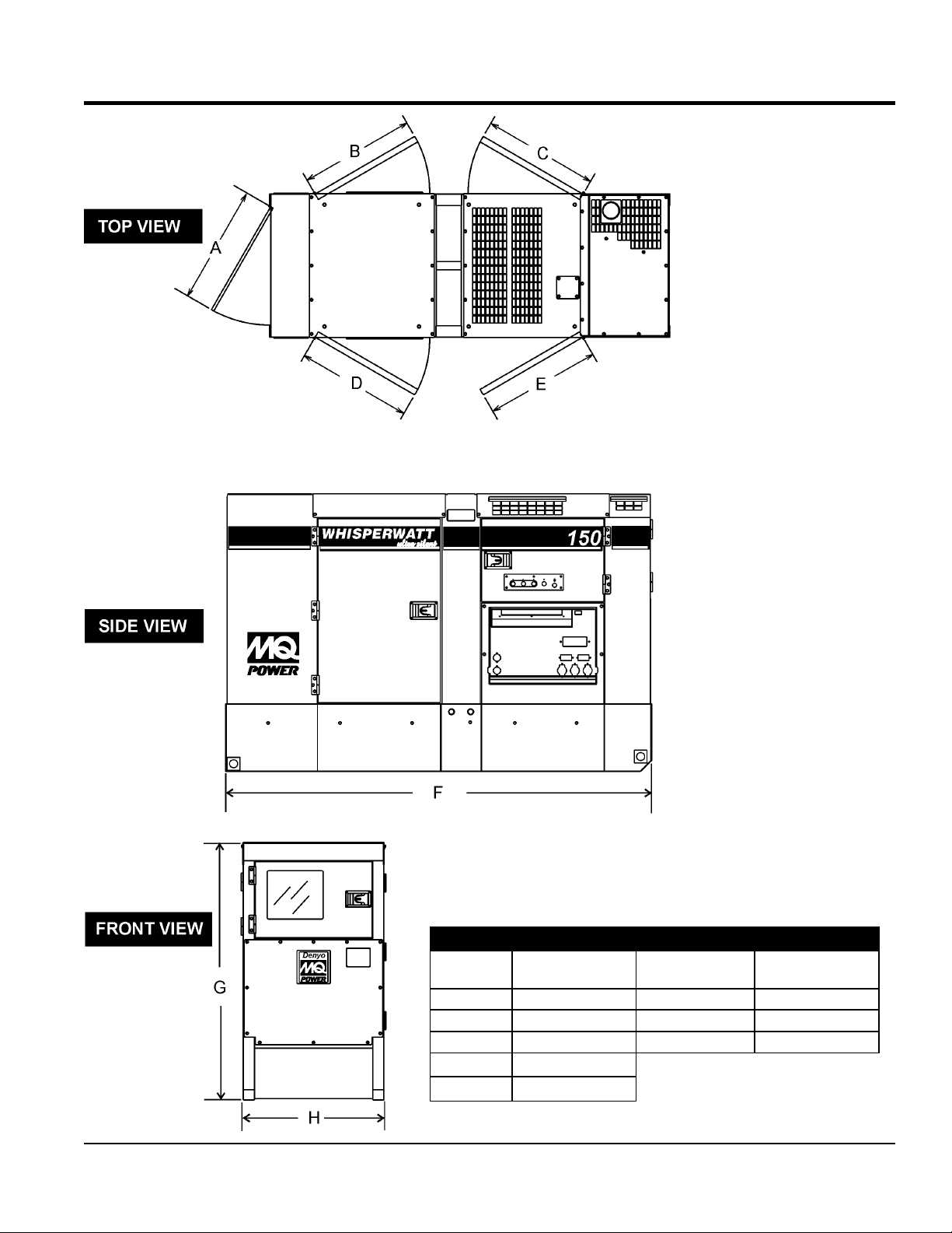
DIMENSIONS
Figure 1. Dimensions
Table 3. Dimensions
Reference
Letter
A 42.50 in. (1080 mm.) F 128.00 in. (3,250 mm.)
B 40.20 in. (1020 mm.) G 75.00 in. (1,905 mm.)
C 40.90 in. (1040 mm.) H 48.80 in. (1240 mm.)
D 40.20 in. (1020 mm.)
E 40.90 in. (1040 mm.)
Dimension in. (mm) Reference Letter Dimension in. (mm)
DCA150USJ3CAN 60 HZ GENERATOR • OPERATION AND PARTS MANUAL — REV. #1 (05/19/15) — PAGE 13

GENERATOR
./2.4 M (MINIMUM)
GROUND LUG
GROUND CABLE
INSTALLATION
GROUND ROD FOR
EARTH GROUND.
CONNECT TO BUILDING
GROUND IF APPLICABLE
REFERENCE
NEC 250-83 (C)
8 FT
Figure 2. Typical Generator Grounding Application
PAGE 14 — DCA150USJ3CAN 60 HZ GENERATOR • OPERATION AND PARTS MANUAL — REV. #1 (05/19/15)
INSTALLATION
OUTDOOR INSTALLATION
Install the generator in a area that is free of debris,
bystanders, and overhead obstructions. Make sure the
generator is on secure level ground so that it cannot slide
or shift around. Also install the generator in a manner so
that the exhaust will not be discharged in the direction of
nearby homes.
The installation site must be relatively free from moisture
and dust. All electrical equipment should be protected from
excessive moisture. Failure to do will result in deterioration
of the insulation and will result in short circuits and
grounding.
Foreign materials such as dust, sand, lint and abrasive
materials have a tendency to cause excessive wear to
engine and alternator parts.
CAUTION
Pay close attention to ventilation when operating the
generator inside tunnels and caves. The engine exhaust
contains noxious elements. Engine exhaust must be
routed to a ventilated area.
GENERATOR GROUNDING
To guard against electrical shock and possible damage to
the equipment, it is important to provide a good EARTH
ground.
Article 250 (Grounding) of the National Electrical Code
(NEC) provides guide lines for proper grounding and
specifies that the cable ground shall be connected to the
grounding system of the building as close to the point of
cable entry as practical.
NEC articles 250-64(b) and 250-66 set the following
grounding requirements:
1. Use one of the following wire types to connect the
generator to earth ground.
a. Copper - 8 AWG (5.3 mm2) or larger.
b. Aluminum - 6 AWG (8.4 mm2) or larger.
2. When grounding the generator (Figure 2) connect the
ground cable between the lock washer and the nut on
the generator and tighten the nut fully. Connect the
other end of the ground cable to earth ground.
INDOOR INSTALLATION
Exhaust gases from diesel engines are extremely
poisonous. Whenever an engine is installed indoors the
exhaust fumes must be vented to the outside. The engine
should be installed at least two feet from any outside wall.
Using an exhaust pipe which is too long or too small can
cause excessive back pressure which will cause the engine
to heat excessively and possibly burn the valves.
MOUNTING
The generator must be mounted on a solid foundation (such
as concrete) and set firmly on the foundation to isolate
vibration of the generator when it is running. The generator
must set at least 6 inches above the floor or grade level (in
accordance to NFPA 110, Chapter 5-4.1). DO NOT remove
the metal skids on the bottom of the generator. They are
to resist damage to the bottom of the generator and to
maintain alignment.
3. NEC article 250-52(c) specifies that the earth ground rod
should be buried a minimum of 8 ft. into the ground.
NOTICE
When connecting the generator to any buildings
electrical system ALWAYS consult with a licensed
electrician.
NOTICE
This generator has a permanent bonding conductor
between the generator stator windings and the frame.
DCA150USJ3CAN 60 HZ GENERATOR • OPERATION AND PARTS MANUAL — REV. #1 (05/19/15) — PAGE 15

GENERAL INFORMATION
GENERATOR
This MQ Power generator (Figure 3) is a high quality
portable (requires a trailer for transport) power source for
telecom sites, lighting facilities, power tools, submersible
pumps and other industrial and construction machinery.
ENGINE OPERATING PANEL
The “Engine Operating Panel” is provided with the following:
Tachometer
Water Temperature Gauge
Oil Pressure Gauge
Charging Ammeter Gauge
Fuel Level Gauge
Panel Light/Panel Light Switch
ECU Controller
Engine Speed Switch
Emergency Stop Button
Emergency Stop Lamp
Warning Lamp
Pre-Heat Lamp
Fuel Leak Detected Alarm Lamp
Diagnostic Gauge
GENERATOR CONTROL PANEL
The “Generator Control Panel” is provided with the following:
Frequency Meter (Hz)
AC Ammeter (Amps)
AC Voltmeter (Volts)
Ammeter Change-Over Switch
Voltmeter Change-Over Switch
Voltage Regulator
3-Pole, 400 amp Main Circuit Breaker
“Control Box” (located behind the Gen. Control Panel)
• Automatic Voltage Regulator
• Current Transformer
• Over-Current Relay
• Starter Relay
• Voltage Selector Switch
OUTPUT TERMINAL PANEL
The “Output Terminal Panel” is provided with the following:
Three 120/240V output receptacles (CS-6369), 50A
Three auxiliary circuit breakers, 50A
Two 120V output receptacles (GFCI), 20A
Two GFCI circuit breakers, 20A
Five output terminal lugs (3Ø power)
OPEN DELTA EXCITATION SYSTEM
This generator is equipped with the state of the art “OpenDelta” excitation system. The open delta system consist
of an electrically independent winding wound among
stationary windings of the AC output section.
There are four connections of the open delta A, B, C and
D. During steady state loads, the power from the voltage
regulator is supplied from the parallel connections of A to
B, A to D, and C to D. These three phases of the voltage
input to the voltage regulator are then rectified and are the
excitation current for the exciter section.
When a heavy load, such as a motor starting or a short
circuit occurs, the automatic voltage regulator (AVR)
switches the configuration of the open delta to the series
connection of B to C. This has the effect of adding the
voltages of each phase to provide higher excitation to the
exciter section and thus better voltage response during the
application of heavy loads.
The connections of the AVR to the AC output windings are
for sensing only. No power is required from these windings.
The open-delta design provides virtually unlimited excitation
current, offering maximum motor starting capabilities. The
excitation does not have a “fixed ceiling” and responds
according the demands of the required load.
ENGINE
This generator unit incorporates an John Deere 6068HF285
diesel engine. This engine is designed to meet every
performance requirement for the generator. Reference
Table 2 for engine specifications.
In keeping with MQ Power’s policy of constantly improving
its products, the specifications quoted herein are subject
to change without prior notice.
ELECTRIC GOVERNOR SYSTEM
The electric governor system controls the RPMs of the engine.
When the engine demand increases or decreases, the
governor system regulates the frequency variation to ±.25%.
EXTENSION CABLES
When electric power is to be provided to various tools or
loads at some distance from the generator, extension cords
are normally used. Cables should be sized to allow for
distance in length and amperage so that the voltage drop
between the generator and point of use (load) is held to
a minimum. Use the cable selection chart (Table 6) as a
guide for selecting proper extension cable size.
PAGE 16 — DCA150USJ3CAN 60 HZ GENERATOR • OPERATION AND PARTS MANUAL — REV. #1 (05/19/15)
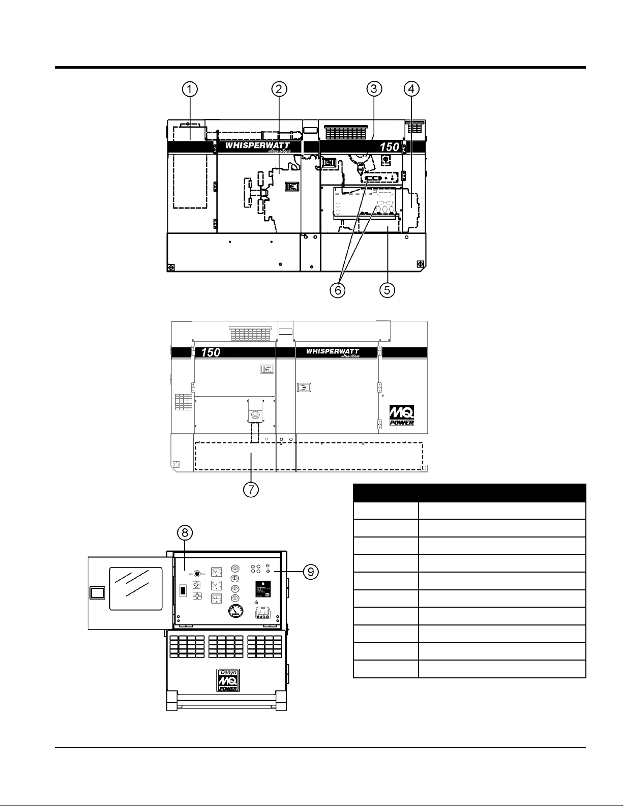
MAJOR COMPONENTS
Table 4. Generator Major Components
ITEM NO. DESCRIPTION
1 Muffler Assembly
2 Engine Assembly
3 Air Filter Assembly
4 Generator Assembly
5 Battery Assembly
6 Output Terminal Assembly
7 Fuel Tank Assembly
8 Generator Control Panel Assembly
9 Engine Operating Panel Assembly
Figure 3. Major Components
DCA150USJ3CAN 60 HZ GENERATOR • OPERATION AND PARTS MANUAL — REV. #1 (05/19/15) — PAGE 17
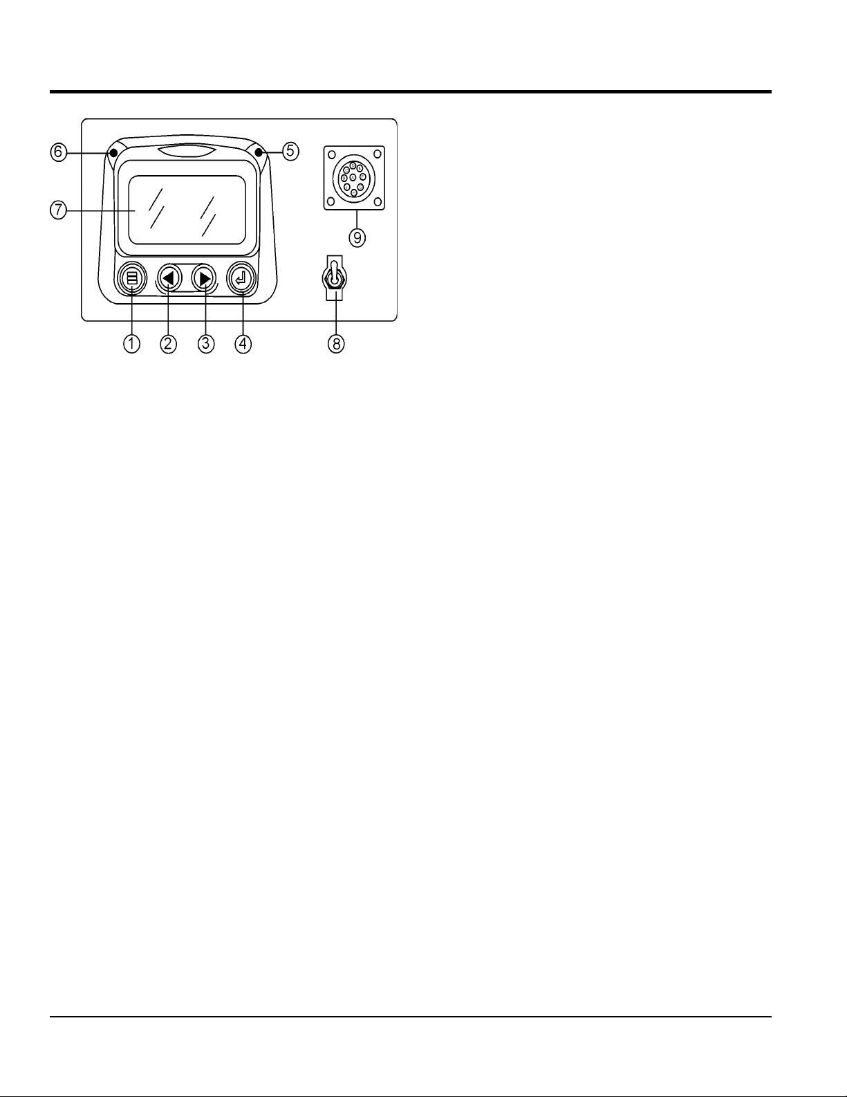
Figure 4. Diagnostic Display
The diagnostic display panel located inside the control
box on the generator (Figure 4) is designed to meet the
needs for instrumentation and control of electronically
controlled engine communication using the SAEJ1939
Controller Area Network (CAN). This diagnostic display is
a multifunction tool that enables equipment operators to
view many different engine parameters and service codes.
The keypad on the diagnostic display panel is a capacitive
touch sensing system. There are no mechanical switches
to wear or stick. This keypad (display unit) will operate in
extreme hot or cold weather conditions.
Other components in the system are microprocessor-based
components for displaying critical engine data broadcast
by an electronic engine or transmission’s Engine Control
Unit (ECU): engine RPM, oil pressure, coolant temperature,
system voltage, etc., and a combination audible alarm and
relay unit for warning and shutdown annunciation.
The Engine Control Unit (ECU) used with this generator
diagnosis engine faults that arise with the the engine
control system and the engine itself. Engine faults can
be determined by viewing the Diagnostic Trouble Codes
(Active Fault Codes) which are displayed on the Diagnostic
Display Panel. See the John Deere Engine Operator’s
Manual for a complete listing of active fault codes and
countermeasures.
The following definitions describe the controls and functions
of the Diagnostic Display Panel (Figure 4).
1. Menu Button – Press this button to enter or exit menu
screens.
DIAGNOSTIC DISPLAY
2. Left Arrow Button – Press this button to scroll through
the screen either moving the parameter selection
toward the left or upward.
3. Right Arrow Button – Press this button to scroll
through the screen either moving the parameter
selection toward the right or downward.
4. Enter Key Button – Press this button to select the
parameter that is highlighted on the screen.
5. Emergency Stop LED – When lit (RED) indicates a
major fault has occured. This condition will shudown
the generator.
6. Warning LED – When lit (AMBER), indicates a engine
parameter has exceeded its limits (minor fault). The
generator will still run in this condition.
7. Display Screen – Graphical backlight LCD screen.
Back lighting is controlled via menu or external
dimmer potentiometer. The display can show either a
single parameter or a quadrant display showing four
parameters simultaneously.
8. Diagnostic Switch – When placed in the ON position,
will activate the diagnostic display panel.
9. CAN Diagnostic Connector – Controller Area
Network connector. This connector outputs diagnostic
error codes. Connect a scanner or similar device into
this connector to read error codes.
Display Parameters
The following are some of the engine and transmission
parameters displayed on the diagnostic disply panel.
Engine RPM’s
Engine Hours
System Voltage
% Engine Load at current RPM
Coolant Temperature
Oil Pressure
Fuel Economy
Current Fuel Consumption
Throttle Position
Engine Manifold Air Temperature
Active Service Codes
Set Units for Display (English or Metric)
English Configuration Parameters.
PAGE 18 — DCA150USJ3CAN 60 HZ GENERATOR • OPERATION AND PARTS MANUAL — REV. #1 (05/19/15)
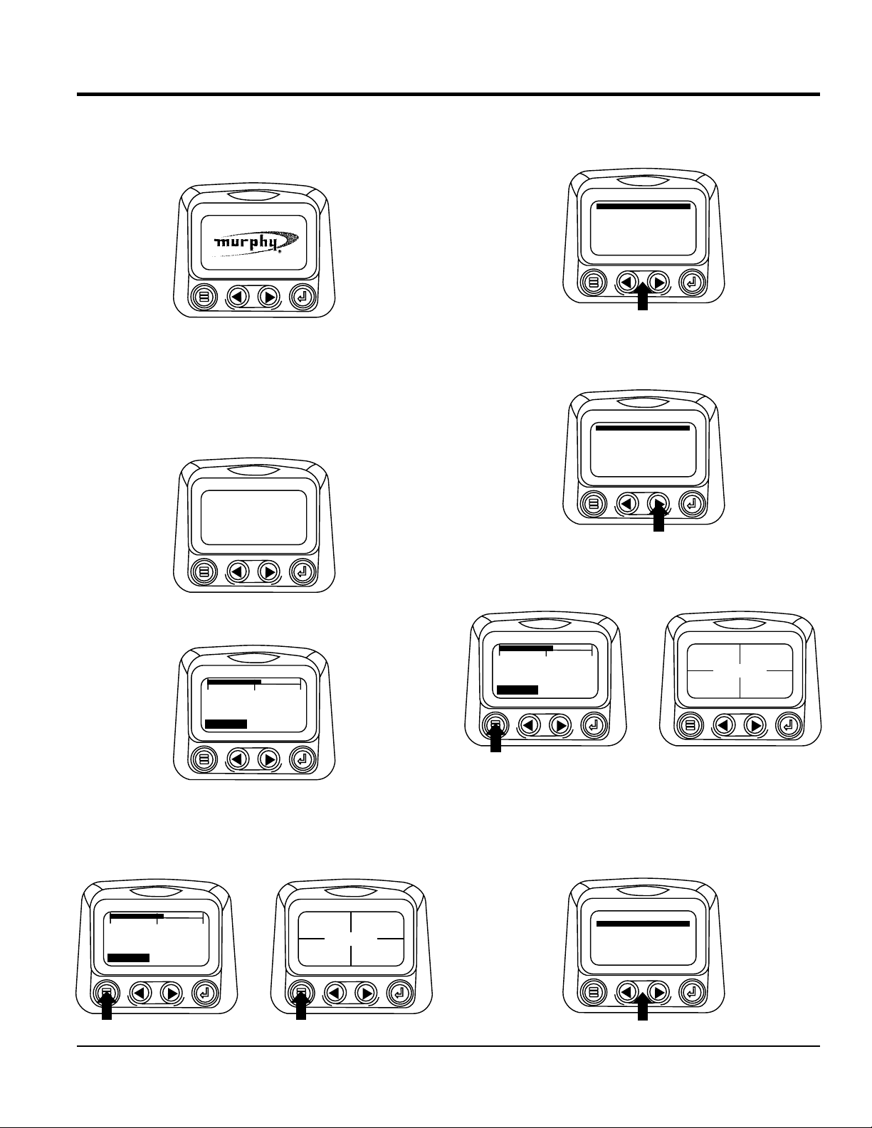
DIAGNOSTIC DISPLAY
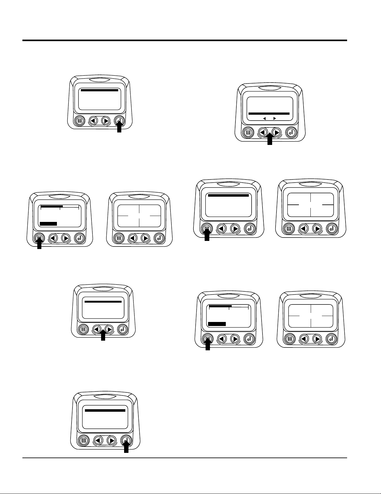
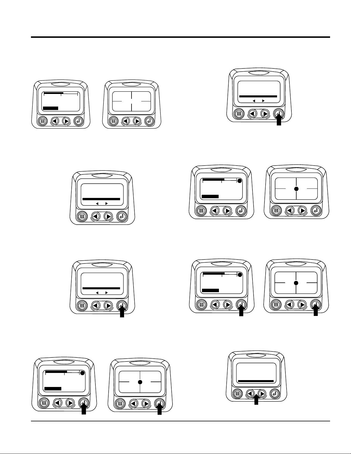
First Time Start Up
1. When power is first applied to the diagnostic display,
the “Logo” is displayed.
2. The “Wait to Start” message will be displayed for
engines with a pre-startup sequence. Once the “Wait
to Start” message is no longer displayed the operator
may start the engine. Note: Displays only when SAE
J1939 message is supported by engine manufacture.
WAIT TO
START
PREHEAT
2. The first seven items of the “Main Menu” will be
displayed. Touching the “Arrow Buttons” will scroll
through the menu selection.
GO TO 1-UP DISPLAY
LANGUAGES
STORED CODES
ENGINE CONF
SETUP 1-UP DISPLAY
SETUP-4-UP DISPLAY
SELECT UNITS
G
3. Touching the right arrow button will scroll down to reveal
the last items of “Main Menu” screen highlighting the
next item down.
ADJUST BACKLIGHT
ADJUST CONTRAST
UTILITIES
3. Once the engine has started the single engine
parameter is displayed.
0
3000
1500
1800 RPM
TEMP
ENG RPM
COOL
Main Menu Navigation
1. Starting at the single or four engine parameter display,
touch “Menu”.
1000 RPM
0
1500
1800 RPM
ENG RPM
COOL
TEMP
3000
98%
LOAD RPM
14.2
BATTVOLT
ENG RPM
57 PSI
OIL PRES
4. Touch the Arrows” to scroll to the desired menu item
or touch “Menu” to exit the Main menu and return to
the engine parameter display.
0
1500
1800 RPM
ENG RPM
COOL
TEMP
3000
98%
LOAD RPM
14.2
BATTVOLT
ENG RPM
57 PSI
OIL PRES
1000 RPM
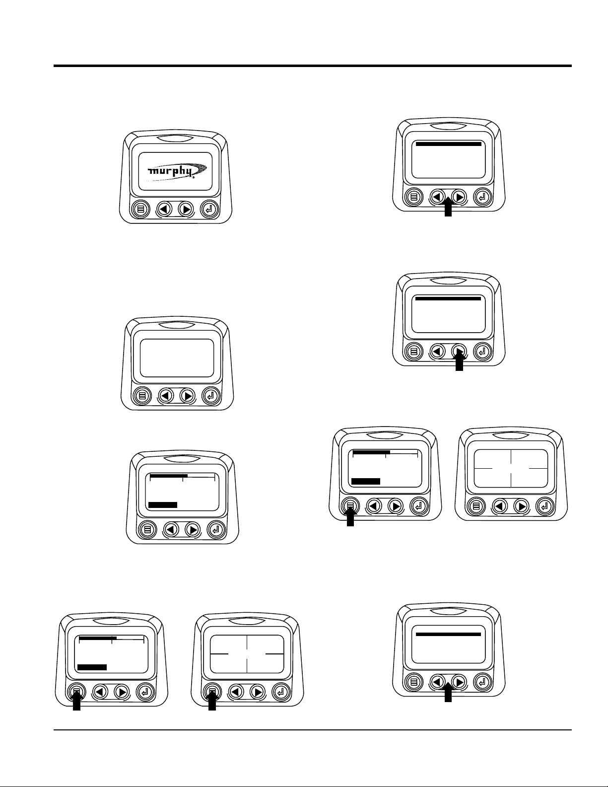
Selecting a Language
1. Starting at the main menu display use the “Arrows to
scroll to the “Language” menu and once highlighted
touch the “Enter” button.
GO TO 1-UP DISPLAY
LANGUAGES
STORED CODES
ENGINE CONF
SETUP 1-UP DISPLAY
SETUP-4-UP DISPLAY
SELECT UNITS
G
DCA150USJ3CAN 60 HZ GENERATOR • OPERATION AND PARTS MANUAL — REV. #1 (05/19/15) — PAGE 19
DIAGNOSTIC DISPLAY
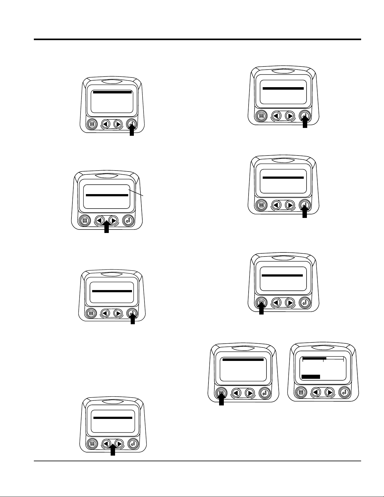
2. The language choices will be displayed. Use the
“Arrow” buttons to scroll through the selections and
touch “Enter” to make a selection.
ENGLISH
ESPANOL
FRANCAIS
DEUTSCH
3. Now that you have selected the language, touch the
“Menu” button to return to the main menu display.
Stored Fault Codes
1. Starting at the single or the four engine parameter
display touch the “Menu button.”.
1000 RPM
0
1500
1800 RPM
COOL
ENG RPM
TEMP
3000
98%
LOAD RPM
14.2
BATTVOLT
ENG RPM
57 PSI
OILPRES
4. If the word “MORE” appears above the “Arrow Buttons”
there are more stored fault codes that may be viewed.
Use the “Arrow Buttons” to scroll to the next Stored
Diagnostic Code.
1ofx
SPN110 FMI10
HIGH COOLANT TEMP
MORE
HIDE
5. Touch the “Menu Button” to exit the Main menu and
return to the engine parameter display.
GO TO 1-UP DISPLAY
STORED CODES
ENGINE CONF
SETUP 1-UP DISPLAY
SETUP-4-UP DISPLAY
SELECT UNITS
ADJUST BACKLIGHT
G
98%
LOAD RPM
14.2
BATTVOLT
1000 RPM
ENG RPM
57 PSI
OIL PRES
2. The main menu will pop up on the display. Use the
“Arrow Buttons” to scroll through the menu until the
Stored Fault Codes is highlighted.
GO TO 1-UP DISPLAY
STORED CODES
G
ENGINE CONF
SETUP 1-UP DISPLAY
SETUP-4-UP DISPLAY
SELECT UNITS
ADJUST BACKLIGHT
3. Once the “Stored Fault Codes” menu item has been
highlighted touch the “Enter Button” to view the “Stored
Fault Codes” (when applicable, consult engine or
transmission manufacturer for SAE J1939 supported
parameters).
GO TO 1-UP DISPLAY
STORED CODES
ENGINE CONF
SETUP 1-UP DISPLAY
SETUP-4-UP DISPLAY
SELECT UNITS
ADJUST BACKLIGHT
G
Engine Configuration Data
1. Starting at the single or four engine parameter display
touch the “Menu Button”. First Time Start Up
1000 RPM
0
1500
1800 RPM
COOL
ENG RPM
TEMP
3000
98%
LOAD RPM
14.2
BATTVOLT
ENG RPM
57 PSI
OIL PRES
PAGE 20 — DCA150USJ3CAN 60 HZ GENERATOR • OPERATION AND PARTS MANUAL — REV. #1 (05/19/15)
DIAGNOSTIC DISPLAY
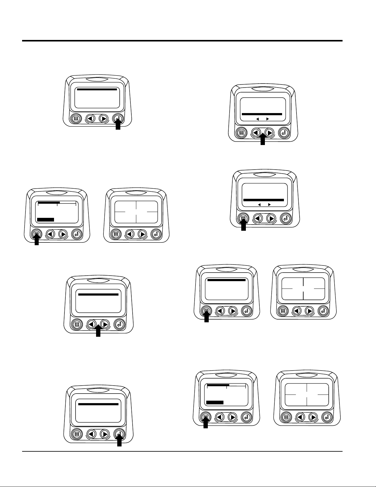
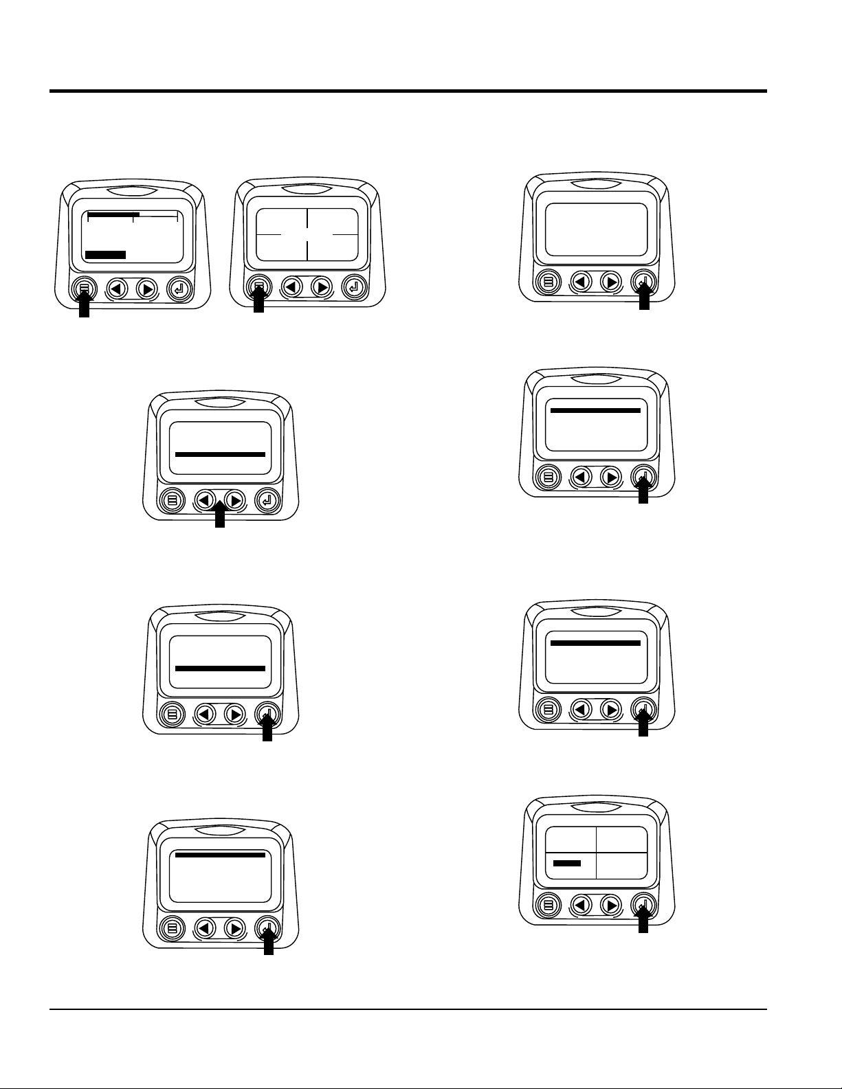
First Time Start-Up
1. When power is first applied to the diagnostic display,
the “Logo” is displayed.
2. The “Wait to Start” message will be displayed for
engines with a pre-startup sequence. Once the “Wait
to Start” message is no longer displayed the operator
may start the engine. Note: Displays only when SAE
J1939 message is supported by engine manufacturrg.
WAIT TO
START
PREHEAT
2. The The first seven items of the “Main Menu” will be
displayed. Touching the “Arrow Buttons” will scroll
through thr menu selection.
GO TO 1-UP DISPLAY
LANGUAGES
STORED CODES
ENGINE CONF
SETUP 1-UP DISPLAY
SETUP-4-UP DISPLAY
SELECT UNITS
G
3. Touching the right arrow button will scroll down to reveal
the last items of “Main Menu” screen highlighting the
next item down.
ADJUST BACKLIGHT
ADJUST CONTRAST
UTILITIES
3. Once the engine has started the single engine
parameter is displayed.
0
3000
1500
1800 RPM
TEMP
ENG RPM
COOL
Main Menu Navigation
1. Starting at the single or four engine parameter display,
touch “Menu”.
0
1500
1800 RPM
COOL
ENG RPM
TEMP
3000
98%
LOAD RPM
14.2
BATTVOLT
1000 RPM
ENG RPM
57 PSI
OIL PRES
4. Touch the Arrows” to scroll to the desired menu item
or touch “Menu” to exit the Main menu and return to
the engine parameter display.
0
1500
1800 RPM
ENG RPM
COOL
TEMP
3000
98%
LOAD RPM
14.2
BATTVOLT
ENG RPM
57 PSI
OIL PRES
1000 RPM
Selecting a Language
1. Starting at the main menu display use the “Arrows to
scroll to the “Language” menu and once highlighted
touch the “Enter” button.
GO TO 1-UP DISPLAY
LANGUAGES
STORED CODES
ENGINE CONF
SETUP 1-UP DISPLAY
SETUP-4-UP DISPLAY
SELECT UNITS
G
DCA150USJ3CAN 60 HZ GENERATOR • OPERATION AND PARTS MANUAL — REV. #1 (05/19/15) — PAGE 21
ENGLISH
ESPANOL
FRANCAIS
DEUTSCH
DIAGNOSTIC DISPLAY
2. The language choices will be displayed. Use the
“Arrow” buttons to scroll through the selections and
touch “Enter” to make a selection.
3. Now that you have selected the language, touch the
“Menu” button to return to the main menu display.
Stored Fault Codes
1. Starting at the single or the four engine parameter
display touch the “Menu button”.
1000 RPM
0
1500
1800 RPM
COOL
ENG RPM
TEMP
3000
98%
LOAD RPM
14.2
BATTVOLT
ENG RPM
57 PSI
OIL PRES
4. f the word “MORE” appears above the “Arrow Buttons”
there are more stored fault codes that may be viewed.
Use the “Arrow Buttons” to scroll to the next Stored
Diagnostic Code.).
1ofx
SPN110 FMI10
HIGH COOLANT TEMP
MORE
HIDE
5. Touch the “Menu Button to return to the main menu.
1ofx
SPN110 FMI10
HIGH COOLANT TEMP
MORE
HIDE
2. The main menu will pop up on the display. Use the
“Arrow Buttons” to scroll through the menu until the
Stored Fault Codes is highlighted.
GO TO 1-UP DISPLAY
STORED CODES
ENGINE CONF
SETUP 1-UP DISPLAY
SETUP-4-UP DISPLAY
SELECT UNITS
ADJUST BACKLIGHT
G
3. Once the “Stored Fault Codes” menu item has been
highlighted touch the “Enter Button” to view the “Stored
Fault Codes” (when applicable, consult engine or
transmission manufacturer for SAE J1939 supported
parameters
GO TO 1-UP DISPLAY
STORED CODES
ENGINE CONF
SETUP 1-UP DISPLAY
SETUP-4-UP DISPLAY
SELECT UNITS
ADJUST BACKLIGHT
G
6. Touch the “Menu Button” to exit the Main menu and
return to the engine parameter display.
GO TO 1-UP DISPLAY
STORED CODES
ENGINE CONF
G
SETUP 1-UP DISPLAY
SETUP-4-UP DISPLAY
SELECT UNITS
ADJUST BACKLIGHT
LOAD RPM
BATTVOLT
98%
14.2
1000 RPM
ENG RPM
57 PSI
OIL PRES
Engine Configuration Data
1. Starting at the single or four engine parameter display
touch the “Menu Button”.
1000 RPM
0
1500
1800 RPM
ENG RPM
COOL
TEMP
3000
98%
LOAD RPM
14.2
BATTVOLT
ENG RPM
57 PSI
OIL PRES
PAGE 22 — DCA150USJ3CAN 60 HZ GENERATOR • OPERATION AND PARTS MANUAL — REV. #1 (05/19/15)

COOL
1800 RPM
0
1500
3000
TEMP
ENG RPM
98%
14.2
57 PSI
1000 RPM
LOAD RPM
BATTVOLT
ENG RPM
OILPRES
ENGINE OIL PRESSURE
GAGE NOT RESPONDING
1ofx
HIDE
DIAGNOSTIC DISPLAY
2. The main menu will pop up on the display. Use the
“Arrow Buttons” to scroll through the menu until the
“Engine Configuration” menu item has been highlighted
.
GO TO 1-UP DISPLAY
STORED CODES
ENGINE CONFG
SETUP 1-UP DISPLAY
SETUP-4-UP DISPLAY
SELECT UNITS
ADJUST BACKLIGHT
3. Once the “Engine Configuration” menu item has been
highlighted touch the “Enter Button” to view the engine
configuration data.
GO TO 1-UP DISPLAY
STORED CODES
ENGINE CONFG
SETUP 1-UP DISPLAY
SETUP-4-UP DISPLAY
SELECT UNITS
ADJUST BACKLIGHT
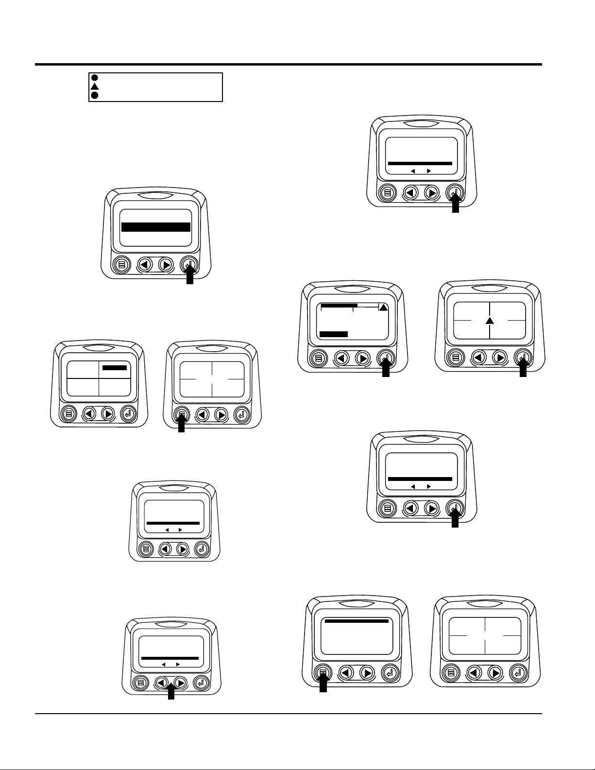
FAULTS AND WARNING
Auxiliary Gage Fault
1. During normal operation the single or four parameter
screen will be displayed.
2. The PVA Series of auxiliary gages can be attached to
the PowerView. These auxiliary gages communicate
with the Modbus master PowerView via a daisy-chained
RS-485 port. If at any time during system initialization
or normal operation an auxiliary gage should fail, the
single or four parameter screen will be replaced with
the “MLink Gage Fault” message.
4. Use the “Arrow Buttons” to scroll through the engine
configuration data.
ENGINE SPEED PT 1
1800 RPM
MORE
5. Touch the “Menu Button” to return to the main menu.
ENGINE SPEED PT 1
1800 RPM
MORE
6. Touch the “Menu Button” to exit the Main menu and
return to the engine parameter display.
3. To acknowledge and “Hide” the fault and return to the
single or four parameter display, touch the “Enter
Button.
1ofx
ENGINE OIL PRESSURE
GAGE NOT RESPONDING
HIDE
4. The display will return to the single or four parameter
screen.
0
1500
1800 RPM
ENG RPM
COOL
3000
TEMP!
!
98%
LOAD RPM
14.2
BATTVOLT
1000 RPM
ENG RPM
!
57 PSI
OIL PRES
!
DCA150USJ3CAN 60 HZ GENERATOR • OPERATION AND PARTS MANUAL — REV. #1 (05/19/15) — PAGE 23
!
98%
14.2
57 PSI
1000 RPM
LOAD RPM
BATTVOLT
ENG RPM
OIL PRES
125°F
COOL TEMP
143°F
OIL TEMP
57 PSI
1000 RPM
ENG RPM
OILPRES
SPN110 FMI10
HIGH COOLANT TEMP
WARNING
1ofx
MORE
HIDE
SPN110 FMI10
HIGH COOLANT TEMP
1ofx
MORE
HIDE
Indicates Auxiliary Gage Fault
!
Indicates Fault Warning
!
Indicates Derate or Shutdown Condition Fault
5. Touching the “Enter Button” will redisplay the hidden
fault. Touching the “Enter Button” once again will hide
the fault and return the screen to the single or four
parameter display. NOTE: The fault can only be cleared
by correcting the cause of the fault condition.
1ofx
ENGINE OIL PRESSURE
GAGE NOT RESPONDING
HIDE
DIAGNOSTIC DISPLAY
4. To acknowledge and “Hide” the fault and return to the
single or four parameter display touch the “Enter
Button”.
1ofx
SPN110 FMI10
HIGH COOLANT TEMP
MORE
5. The display will return to the single or four parameter
display but the display will contain the “Active Fault”
warning icon. Touching the “Enter Button” will redisplay
the hidden fault.
HIDE
Active Fault Codes
1. During normal operation the single or four parameter
screen will be displayed
2. When the PowerView receives a fault code from an
engine control unit the single or four parameter screen
will be replaced with the “Active Fault Codes” message.
3. If the word “MORE” appears above the “Arrow Buttons”,
there are more active fault codes that may be viewed.
Use the “Arrow Buttons” to scroll to the next “Active
Fault Code”.
1000 RPM
0
1500
1800 RPM
ENG RPM
COOL
3000
TEMP!
!
98%
LOAD RPM
14.2
BATTVOLT
!
ENG RPM
57 PSI
OIL PRES
!
6. Touching the “Enter Button” once again will hide the
fault and return the screen to the single or four
parameter display.
1ofx
WARNING
SPN110 FMI10
HIGH COOLANT TEMP
MORE
HIDE
7. The Single or Four parameter screen will display the
fault icon until the fault condition is corrected. NOTE:
Ignoring active fault codes could result in severe engine
damage.
GO TO 1-UP DISPLAY
STORED CODES
ENGINE CONF
SETUP 1-UP DISPLAY
SETUP-4-UP DISPLAY
SELECT UNITS
ADJUST BACKLIGHT
G
98%
LOAD RPM
14.2
BATTVOLT
1000 RPM
ENG RPM
57 PSI
OIL PRES
PAGE 24 — DCA150USJ3CAN 60 HZ GENERATOR • OPERATION AND PARTS MANUAL — REV. #1 (05/19/15)
DIAGNOSTIC DISPLAY
Shutdown Codes
1. During normal operation the single or four parameter
screen will be displayed
1000 RPM
0
1500
1800 RPM
COOL
ENG RPM
3000
TEMP
98%
LOAD RPM
14.2
BATTVOLT
2. When the diagnostic display receives a severe fault
code from an engine control unit the single or four
parameter screen will be replaced with the “Shutdown”
message.
1ofx
SHUTDOWN
SPN110 FMI10
HIGH COOLANT TEMP
MORE
HIDE
ENG RPM
57 PSI
OILPRES
5. Touching the “Enter Button” once again will hide the
fault and return the screen to the single or four
parameter display.
1ofx
SHUTDOWN
SPN110 FMI10
HIGH COOLANT TEMP
MORE
HIDE
6. The Single or Four parameter screen will display the
fault icon until the fault condition is corrected. NOTE:
Ignoring active fault codes could result in severe engine
damage.
0
1500
1800 RPM
ENG RPM
COOL
3000
TEMP!
!
98%
LOAD RPM
14.2
BATTVOLT
1000 RPM
ENG RPM
!
57 PSI
OIL PRES
!
3. To acknowledge and “Hide” the fault and return to the
single or four parameter display touch the “Enter
Button”.
1ofx
SHUTDOWN
SPN110 FMI10
HIGH COOLANT TEMP
MORE
HIDE
4. The display will return to the single or four parameter
display, but the display will contain the “Shut Down”
icon. Touching the “Enter Button” will redisplay the
hidden fault.
0
1500
1800 RPM
COOL
ENG RPM
3000
TEMP!
!
98%
LOAD RPM
14.2
BATTVOLT
1000 RPM
ENG RPM
!
57 PSI
OIL PRES
Backlight Adjustment
1. Starting at the single or four engine parameter display
touch the “Menu Button”.
0
1500
1800 RPM
ENG RPM
COOL
3000
TEMP!
!
98%
LOAD RPM
14.2
BATTVOLT
2. The main menu will pop up on the display. Use the
“Arrow Buttons” to scroll through the menu until the
“Adjust Backlight” is highlighted.
GO TO 1-UP DISPLAY
STORED CODES
GENGINECONF
SETUP 1-UP DISPLAY
SETUP-4-UP DISPLAY
SELECT UNITS
ADJUST BACKLIGHT
1000 RPM
ENG RPM
!
57 PSI
OIL PRES
DCA150USJ3CAN 60 HZ GENERATOR • OPERATION AND PARTS MANUAL — REV. #1 (05/19/15) — PAGE 25

DIAGNOSTIC DISPLAY
3. Once the “Adjust Backlight” menu item has been
highlighted touch the “Enter Button” to activate the
“Adjust Backlight” function
GO TO 1-UP DISPLAY
STORED CODES
SETUP 1-UP DISPLAY
SETUP-4-UP DISPLAY
SELECT UNITS
ADJUST BACKLIGHT
GENGINE CONF
4. Use the “Arrow Buttons” to select the desired backlight
intensity.
ADJUST BACKLIGHT
CONTRAST ADJUSTMENT
1. Starting at the single or four engine parameter display,
touch the “Menu Button”.
98%
0
1500
1800 RPM
ENG RPM
COOL
3000
TEMP
LOAD RPM
14.2
BATTVOLT
2. The main menu will pop up on the display. Use the
“Arrow Buttons” to scroll through the menu until “Adjust
Contrast” is highlighted.
GO TO 1-UP DISPLAY
STORED CODES
ENGINE CONF
SETUP 1-UP DISPLAY
SETUP-4-UP DISPLAY
SELECT UNITS
ADJUST BACKLIGHT
G
1000 RPM
ENG RPM
57 PSI
OIL PRES
5. Touch the “Menu Button” to return to the main menu.
ADJUST BACKLIGHT
6. Touch the “Menu Button” to exit the Main menu and
return to the engine parameter display
GO TO 1-UP DISPLAY
STORED CODES
ENGINE CONF
SETUP 1-UP DISPLAY
SETUP-4-UP DISPLAY
SELECT UNITS
ADJUST BACKLIGHT
G
LOAD RPM
14.2
BATTVOLT
98%
1000 RPM
ENG RPM
57 PSI
OIL PRES
3. Once the “Adjust Contrast” menu item has been
highlighted touch the “Enter Button” to activate the
“Adjust Contrast” function.
STORED CODES
ENGINE CONF
SETUP 1-UP DISPLAY
SETUP-4-UP DISPLAY
SELECT UNITS
ADJUST BACKLIGHT
ADJUST CONTRAST
G
4. Use the “Arrow Buttons” to select the desired contrast
intensity.
ADJUST CONTRAST
5. Touching the “Menu Button” will take you back through
the menus.
PAGE 26 — DCA150USJ3CAN 60 HZ GENERATOR • OPERATION AND PARTS MANUAL — REV. #1 (05/19/15)

DIAGNOSTIC DISPLAY
Select Units
1. Starting at the single or four engine parameter display
touch the “Menu Button”.
1000 RPM
98%
0
1500
1800 RPM
COOL
ENG RPM
3000
TEMP
LOAD RPM
14.2
BATTVOLT
2. The main menu will pop up on the display. Use the
arrow buttons to scroll through the menu until the
“Select Units” is highlighted.
GO TO 1-UP DISPLAY
STORED CODES
ENGINE CONF
SETUP 1-UP DISPLAY
SETUP-4-UP DISPLAY
SELECT UNITS
ADJUST BACKLIGHT
G
ENG RPM
57 PSI
OIL PRES
5. Touch the “Enter Button” to select the highlighted units.
ENGLISH
METRIC KPA
METRIC BAR
6. Touch the “Menu Button” to return to the “Main Menu”.
ENGLISH
METRIC KPA
METRIC BAR
*
7. Touch the “Menu Button” to exit the Main menu and
return to the engine parameter display.
3. Once the “Select Units” menu item has been highlighted
touch the “Enter Button” to access the “Select Units”
function.
GO TO 1-UP DISPLAY
STORED CODES
ENGINE CONF
SETUP 1-UP DISPLAY
SETUP-4-UP DISPLAY
SELECT UNITS
ADJUST BACKLIGHT
G
4. Use the arrows to highlight the desired units. “English”
for imperial units i.e. PSI,”F or Metric kPa, Metric Bar
for IS units i.e. kPa, Bar, “C".
ENGLISH
ESPANOL
FRANCAIS
DEUTSCH
GO TO 1-UP DISPLAY
STORED CODES
G
ENGINE CONF
SETUP 1-UP DISPLAY
SETUP-4-UP DISPLAY
SELECT UNITS
ADJUST BACKLIGHT
98%
LOAD RPM
14.2
BATTVOLT
1000 RPM
ENG RPM
57 PSI
OILPRES
SETUP 1-UP DISPLAY
1. Starting at the single engine parameter display, touch
the “Menu Button”.
1000 RPM
98%
0
1500
1800 RPM
COOL
ENG RPM
3000
TEMP
LOAD RPM
14.2
BATTVOLT
2. The main menu will pop up on the display. Use the
“Arrow Buttons” to scroll through the menu until the
“Setup 1-up Display” is highlighted.
GO TO 1-UP DISPLAY
STORED CODES
G
ENGINE CONF
SETUP 1-UP DISPLAY
SETUP-4-UP DISPLAY
SELECT UNITS
ADJUST BACKLIGHT
ENG RPM
57 PSI
OILPRES
DCA150USJ3CAN 60 HZ GENERATOR • OPERATION AND PARTS MANUAL — REV. #1 (05/19/15) — PAGE 27

DIAGNOSTIC DISPLAY
the
3. Once the “Setup 1-up Display” menu icon has been
highlighted touch the “Enter Button” to access the
“Setup 1-up display” function.
GO TO 1-UP DISPLAY
STORED CODES
ENGINE CONF
SETUP 1-UP DISPLAY
SETUP-4-UP DISPLAY
SELECT UNITS
ADJUST BACKLIGHT
G
4. Three options are available for modification of the
1-Up display.
a. Use Defaults — This option contains a set of engine
parameters: Engine Hours, Engine RPM. System
Voltage, Battery Voltage, % Engine Load at Current
RPM, Coolant Temperature, Oil Pressure.
b. Custom Setup — This option allows for the
modification of what parameter, the number of
parameters, and the order in which the parameters
are being displayed.
7. A message indicating the “Single Engine” parameter
display parameters are reset to the factory defaults will
be displayed, then the display will return to the “Custom
Setup” menu.
RESTORED TO
DEFAULTS
8. Custom Setup- To perform a custom setup of the 1-Up
Display, use the arrow buttons to scroll to and highlight
“Custom Setup” on the display.
USE DEFAULTS
CUSTOM SETUP
AUTOMATIC SCAN OFF
c. Automatic Scan — Selecting the scan function
will cause the 1-Up Display to scroll through
the selected set of parameters one at a time,
momentarily pausing at each.
5. Use Defaults- To select “Use Defaults” use the arrow
buttons to scroll to and highlight “Use Defaults” in the
menu display.
USE DEFAULTS
CUSTOM SETUP
AUTOMATIC SCAN OFF
6. Touch the “Enter Button” to activate the “Use Defaults”
function.
USE DEFAULTS
CUSTOM SETUP
AUTOMATIC SCAN OFF
9. Touching the “Enter Button” will display a list of engine
parameters.
USE DEFAULTS
CUSTOM SETUP
AUTOMATIC SCAN OFF
10. Use the “Arrow Buttons” to scroll to and highlight a
selected parameter (parameter with a # symbol to right
of it).
ENGINE SPEED
PERCENT LOAD AT CURRENT RPM
ENGINE OIL PRESSURE
ENGINE COOLANT TEMPERATURE
1
3
2
This number indicates
the order of display for
parameters and that the
parameter is selected
for display.
PAGE 28 — DCA150USJ3CAN 60 HZ GENERATOR • OPERATION AND PARTS MANUAL — REV. #1 (05/19/15)
DIAGNOSTIC DISPLAY
ENGINE SPEED
PERCENT LOAD AT CURRENT RPM
ENGINE OIL PRESSURE
ENGINE COOLANT TEMPERATURE
1
3
2
ENGINE SPEED
PERCENT LOAD AT CURRENT RPM
ENGINE OIL PRESSURE
ENGINE COOLANT TEMPERATURE
2
1
3
11. Touch the “Enter Button” to deselect the selected
parameter removing it from the list of parameters being
displayed on the 1-up display.
12. Use the “Arrow Button” to scroll and highlight the
desired parameter that has not been selected for
display.
ENGINE SPEED
PERCENT LOAD AT CURRENT RPM
ENGINE OIL PRESSURE
ENGINE COOLANT TEMPERATURE
2
1
Note that the numbers
now indicatethe new order
of display for the parameters.
13. Touch the “Enter Button” to select the highlighted
parameter for inclusion in the Single Engine Parameter
Display.
16. Touching the “Enter Button” toggles the “Automatic
Scan” function on.
USE DEFAULTS
CUSTOM SETUP
AUTOMATIC SCAN ON
17. Touching the “Enter Button” again toggles the
“Automatic Scan” function off.
USE DEFAULTS
CUSTOM SETUP
AUTOMATIC SCAN OFF
18. Once the “Use Defaults”, “Custom Setup” and
“Automatic Scan” functions have been set touch the
“Menu Button” to return to the main menu.
USE DEFAULTS
CUSTOM SETUP
AUTOMATIC SCAN ON
14. Continue to scroll and select additional parameters for
the custom 1-up Display. Touch the “Menu Button” at
any time to return to the “Custom Setup” menu.
15. Automatic Scan- Selecting the scan function will cause
the 1-Up Display to scroll through the selected set of
parameters one at a time. Use the “Arrow Buttons” to
scroll to the “Automatic Scan” function.
DCA150USJ3CAN 60 HZ GENERATOR • OPERATION AND PARTS MANUAL — REV. #1 (05/19/15) — PAGE 29
19. Touch the “Menu Button” to exit the Main menu and
return to the engine parameter display.
GO TO 1-UP DISPLAY
STORED CODES
ENGINE CONF
SETUP 1-UP DISPLAY
SETUP-4-UP DISPLAY
SELECT UNITS
ADJUST BACKLIGHT
USE DEFAULTS
CUSTOM SETUP
AUTOMATIC SCAN OFF
G
0
1500
1800 RPM
ENG RPM
COOL
3000
TEMP
DIAGNOSTIC DISPLAY
Setup 4-Up Display
1. From the single or four engine parameter display touch
the “Menu Button
98%
0
1500
1800 RPM
ENG RPM
COOL
3000
TEMP
LOAD RPM
14.2
BATTVOLT
2. The main menu will pop up on the display. Use the
“Arrow Buttons” to scroll through the menu until the
“Setup 4-Up Display” is highlighted.
GO TO 1-UP DISPLAY
STORED CODES
ENGINE CONFG
SETUP 1-UP DISPLAY
SETUP-4-UP DISPLAY
SELECT UNITS
ADJUST BACKLIGHT
1000 RPM
ENG RPM
57 PSI
OIL PRES
5. The “Use Defaults” screen will be displayed during the
resetting period then will automatically return to the
“Setup 4- Up Display” menu.
RESTORED TO
DEFAULTS
6. Select the “4-Up Custom Setup” from the “4-Up Setup”
menu.
USE DEFAULTS
CUSTOM SETUP
3. Once the “Setup 4-Up Display” menu item has been
highlighted touch the “Enter Button” to activate the
“Setup 4- Up Display” menu.
GO TO 1-UP DISPLAY
STORED CODES
ENGINE CONFG
SETUP 1-UP DISPLAY
SETUP-4-UP DISPLAY
SELECT UNITS
ADJUST BACKLIGHT
4. Touch the “Enter Button” to activate the “Use Defaults”
function. This action will reset the unit to the factory
default.
USE DEFAULTS
CUSTOM SETUP
AUTOMATIC SCAN OFF
7. The quadrant with the backlit parameter value is the
current selected parameter. Use the “Arrow Buttons”
to highlight the parameter value in the quadrant you
wish to place a new parameter.
USE DEFAULTS
CUSTOM SETUP
8. Touch the “Enter Button” and a list of parameters will
appear.
125°F
COOL TEMP
14.2
BATTVOLT
1000 RPM
ENG RPM
57 PSI
OIL PRES
PAGE 30 — DCA150USJ3CAN 60 HZ GENERATOR • OPERATION AND PARTS MANUAL — REV. #1 (05/19/15)
 Loading...