

Page 1

PARTS AND OPERATION MANUAL
SV-SERIES
VIBRATOR MOTOR
MODEL #
SERIAL #
© COPYRIGHT 2002, MULTIQUIP INC.
Revision #2 (09/16/02)
STOW CONSTRUCTION EQUIPMENTSTOW CONSTRUCTION EQUIPMENT
STOW CONSTRUCTION EQUIPMENT
STOW CONSTRUCTION EQUIPMENTSTOW CONSTRUCTION EQUIPMENT
A DIVISION OF MULTIQUIP INC.
POST OFFICE BOX 6254
CARSON, CA 90749
310-537-3700 • 888-252-STOW [888-252-7869]
FAX: 310-537-1986 • FAX: 800-556-1986
E-MAIL: [email protected] • WWW: stowmfg.com
PARTS DEPARTMENT:
800-427-1244
FAX: 800-672-7877
SERVICE DEPARTMENT/TECHNICAL ASSISTANCE:
800-478-1244
FAX: 310-631-5032
P/N 36199
Page 2

Page 3

HERE'S HOW TO GET HELP
PLEASE HAVE THE MODEL AND SERIAL NUMBER
ON-HAND WHEN CALLING
PARTS DEPARTMENT
800-427-1244 or 310-537-3700
FAX: 800-672-7877 or 310-637-3284
SERVICE DEPARTMENT/TECHNICAL ASSISTANCE
800-478-1244 or 310-537-3700
FAX: 310- 537-4259
WARRANTY DEPARTMENT
888-661-4279, or 310-661-4279
FAX: 310- 537-1173
MAIN
800-421-1244 or 310-537-3700
FAX: 310-537-3927
SV-SERIES VIBRATOR MOTOR — PARTS & OPERATION MANUAL — REV. #2 (09/16/02) — PAGE 3
Page 4

SV-SERIES VIBRATOR MOTOR— TABLE OF CONTENTS
Here's How To Get Help ............................................ 3
Table Of Contents ..................................................... 4
Parts Ordering Procedures ....................................... 5
Safety Message Alert Symbols ................................. 6
Rules For Safe Operation ...................................... 7-9
MQ STOW — SV-SERIES
VIBRATOR MOTOR
Specifications .......................................................... 10
Decals ..................................................................... 11
Preparation & Operation ......................................... 12
Operation ................................................................ 13
Maintenance ........................................................... 14
Troubleshooting ...................................................... 15
Vibrator Motor Assembly ................................... 16-19
Terms and Conditions of Sale ................................. 20
NOTE
Specifications and
part numbers are
subject to change
without notice.
PAGE 4 — SV-SERIES VIBRATOR MOTOR— PARTS & OPERATION MANUAL — REV. #2 (09/16/02)
Page 5

SV-SERIES VIBRATOR MOTOR— PARTS ORDERING PROCEDURES
■■
■ Dealer account number
■■
■■
■ Dealer name and address
■■
■■
■ Shipping address (if different than billing address)
■■
■■
■ Return fax number
■■
■■
■ Applicable model number
■■
■■
■ Quantity, part number and description of each part
■■
■■
■ Specify preferred method of shipment:
■■
UPS Ground
•
UPS Second Day or Third Day*
•
UPS Next Day*
•
Federal Express Priority One (please provide us with your Federal
•
Express account number)*
Airborne Express*
•
Truck or parcel post
•
*Normally shipped the same day the order is received, if prior to 2PM west coast time.
Earn Extra Discounts when
you order by FAX!
All parts orders which include complete part numbers
and are received by fax qualify for the following extra
discounts:
Number of
line items ordered Additional Discount
1-9 items 3%
10+ items** 5%
Get special freight allowances
when you order 10 or more
line items via FAX!**
■■
■
UPS Ground Service at no charge for freight
■■
■■
■
UPS Third Day Service at one-half of actual freight
■■
cost
Extra Fax DiscountExtra Fax Discount
Extra Fax Discount
Extra Fax DiscountExtra Fax Discount
for Domestic USAfor Domestic USA
for Domestic USA
for Domestic USAfor Domestic USA
Dealers OnlyDealers Only
Dealers Only
Dealers OnlyDealers Only
Now! Direct TOLL-FREE access
to our Parts Department!
Toll-free nationwide:
No other allowances on freight shipped by any other carrier.
**Common nuts, bolts and washers (all items under $1.00 list price)
do not count towards the 10+ line items.
*DISCOUNTS ARE SUBJECT TO CHANGE*
Fax order discount and UPS special programs revised June 1, 1995
SV-SERIES VIBRATOR MOTOR — PARTS & OPERATION MANUAL — REV. #2 (09/16/02) — PAGE 5
800-421-1244
Toll-free FAX:
800/6-PARTS-7 • 800-672-7877
Page 6

SV-SERIES VIBRATOR MOTOR— SAFETY MESSAGE ALERT SYMBOLS
FOR YOUR SAFETY AND THE SAFETY OF OTHERS!
Safety precautions should be followed at all times when operating
this equipment. Failure to read and understand the Safety
Messages and Operating Instructions could result in injury to
yourself and others.
HAZARD SYMBOLS
NOTE
This Owner's Manual has been developed to provide
complete instructions for the safe and efficient operation
of the MQ STOW SV-SERIES VIBRATOR MOTOR.
Before using this VIBRATOR MOTOR, ensure that
the operating individual has read and understands
all instructions in this manual.
SAFETY MESSAGE ALERT SYMBOLS
The three (3) Safety Messages shown below will inform you
about potential hazards that could injure you or others. The
Safety Messages specifically address the level of exposure to
the operator, and are preceded by one of three words: DANGER,
WARNING, or CAUTION.
High Temperatures – Unplug the machine
and allow to
and maintenance functions. Contact with
hot!
Accidental Starting
ALWAYS place the motor ON/OFF switch
in the OFF position, when the Vibrator
Motor is not in use.
Sight and Hearing hazard
ALWAYS wear approved eye and hearing
protection.
Burn Hazard
cool
before performing service
components can cause serious burns.
DANGER: You WILL be KILLED or
SERIOUSLY injured if you DO NOT follow
directions.
WARNING: You CAN be KILLED or
SERIOUSLY injured if you DO NOT follow
directions.
NEVER operate the Vibrator Motor in
an explosive atmosphere or near
combustible materials. An explosion or
fire could result causing severe
harm or even death.
CAUTION: You CAN be injured if you
DO NOT follow directions.
Potential hazards associated with SV-SERIES VIBRATOR
MOTOR operation will be referenced with "
which appear throughout this manual, and will be referenced in
conjunction with Safety "
Message Alert Symbols
Hazard Symbols
".
"
Explosive Fuel
bodily
PAGE 6 — SV-SERIES VIBRATOR MOTOR— PARTS & OPERATION MANUAL — REV. #2 (09/16/02)
Page 7

SV-SERIES VIBRATOR MOTOR— RULES FOR SAFE OPERATION
CAUTION:
Failure to follow instructions in this manual may
lead to serious injury. This equipment is to be
operated by trained and qualified personnel
only! This equipment is for industrial use only.
■
ALWAYS check the Vibrator Motor for loosened threads or
bolts before starting.
■
NEVER use accessories or attachments, which are not
recommended by Stow for this equipment. Damage to the
equipment and/or injury to user may result.
The following safety guidelines should always be used when
operating the SV-SERIES VIBRATOR MOTOR.
SAFETY
■
DO NOT operate or service this equipment
before reading this entire manual.
■
ALWAYS use proper lifting techniques
when using the the Vibrator Motor, flexible
shaft and vibrator head assembly.
■
ALWAYS check to make sure that the operating area is clear
before starting the Vibrator Motor.
■
NEVER leave the machine
■
Keep the Vibrator Motor in proper running condition.
■
Make sure that there is no buildup of concrete, grease, oil or
debris on the Vibrator Motor.
■
Fix damage to the Vibrator Motor immediately and always
replace broken parts.
■
This equipment should not be operated by persons under 18
years of age.
unattended
while running.
EMERGENCIES
■
ALWAYS know the location of
the nearest
■
ALWAYS know the location of the
nearest and
■
In emergencys
nearest phone or
Also know the phone numbers of the nearest
ambulance, doctor
information will be invaluable in the case of an
emergency.
fire extinguisher
first aid kit
always
.
.
know the location of the
keep a phone on the job site
and
fire department
.
. This
■
NEVER operate this equipment without proper
protective clothing, shatterproof glasses, steeltoed boots and other protective devices required
by the job.
■
NEVER operate this equipment when not feeling
well due to fatigue, illness or taking medicine.
■
NEVER operate this equipment under the
influence or drugs or alcohol.
SV-SERIES VIBRATOR MOTOR — PARTS & OPERATION MANUAL — REV. #2 (09/16/02) — PAGE 7
Page 8

SV-SERIES VIBRATOR MOTOR— RULES FOR SAFE OPERATION
SAFETY INSTRUCTIONS
For the safety of yourself and others working around you, it is
EXTREMELY
■
NEVER operate a vibrator motor while under the influence of
drugs, alcohol, or medications that may impair the senses or
reactions.
■
Dress properly. Wear appropriate clothing and protective
safety equipment. Wear clothing that will not likely become
caught in the equipment or snag on the forms. Eye, hand,
hearing, and foot safety equipment is required.
■
Keep untrained personnel away. DO NOT let visitors contact
the vibrator unit. All visitors should be kept away from the
work area.
■
ALWAYS disconnect the motor from the power source when
not in use, before servicing, and when changing flexible
shafting and vibrator heads.
■
DO NOT abuse the motor cord.
■
NEVER carry the motor by the cord. Use the carrying frame.
■
DO NOT yank the cord to disconnect it from the receptacle.
Grasp the plug itself to disconnect it.
■
Keep the cord from heat, oil, and sharp objects.
■
Avoid unintentional starting.
■
DO NOT carry plugged-in motor with finger on the switch.
■
Be sure switch is in the "OFF" position before plugging the
motor into a power source.
■
DO NOT overload the motor. It will do a better and safer job
at the rate for which it was designed.
■
DO NOT expose vibrator motor to rain.
■
DO NOT use vibrator motor in damp or wet locations without
proper electrical circuits.
important that you observe the following rules:
■
The use of any attachment or accessory not intended for use
with this vibrator motor may present a risk of injury to the
operator or other personnel.
■
Maintain tools with care.
■
Keep vibrator motor clean for better and safer operation.
■
Inspect motor cord periodically and if damaged, have
itrepaired by an authorized service facility.
■
Use only factory authorized identica
■
Check for damaged parts.
■
Before each use
there are no damaged parts, and that all parts function
properly, (examples: switch, cord housing). If any damage or
malfunctioning parts are found, have them repaired or
replaced by an authorized service facility.
■
NEVER use the motor with a defective switch. If the switch
does not turn the motor "ON" or "OFF", have it replaced before
using the motor.
■
Before plugging the motor into a power source, ALWAYS
remove any wrenches or other tools from the motor, shaft,
and head that were used for assembly.
■
ALWAYS
■
DO NOT force the motor and head to do the job of a larger
motor and head.
■
DO NOT use this motor for anything other than its intended
use.
■
Store idle vibrator motor. When not in use, motor should be
stored in a dry, safe storage area.
■
SAVE THESE INSTRUCTIONS. Keep these instructions in
a safe place for future reference.
WARNING!WARNING!
WARNING!
WARNING!WARNING!
l replacement parts
ALWAYS
use the correct tool for the job.
check the motor to make certain
.
■
DO NOT use the vibrator in the presence of flammable liquids
or gases.
■
Keep work area well lit.
■
Keep work area clean. A cluttered area invites injuries.
■
DO NOT overreach. Keep proper footing and balance at all
times.
■
Secure forms. Make sure the form work is well made and
braced to withstand the stresses made by vibration.
PAGE 8 — SV-SERIES VIBRATOR MOTOR— PARTS & OPERATION MANUAL — REV. #2 (09/16/02)
1. Know your concrete vibrator. Read this instruction manual.
2. Guard against electrical shock.
3. Prevent body contact with grounded surfaces. (For example:
When using electric tools, basic safety
precautions should ALWAYS be followed to
reduce the risk of fire, electric shock, and
personal injury.
Learn the vibrator's applications, limitations, and specific
potential hazards peculiar to this tool.
pipes, reiforcing bar, etc.)
Page 9
SV-SERIES VIBRATOR MOTOR— RULES FOR SAFE OPERATION
■
Use a protection wiring device, such as a Ground Fault
Circuit Interrupter, for the protection of personnel.
■
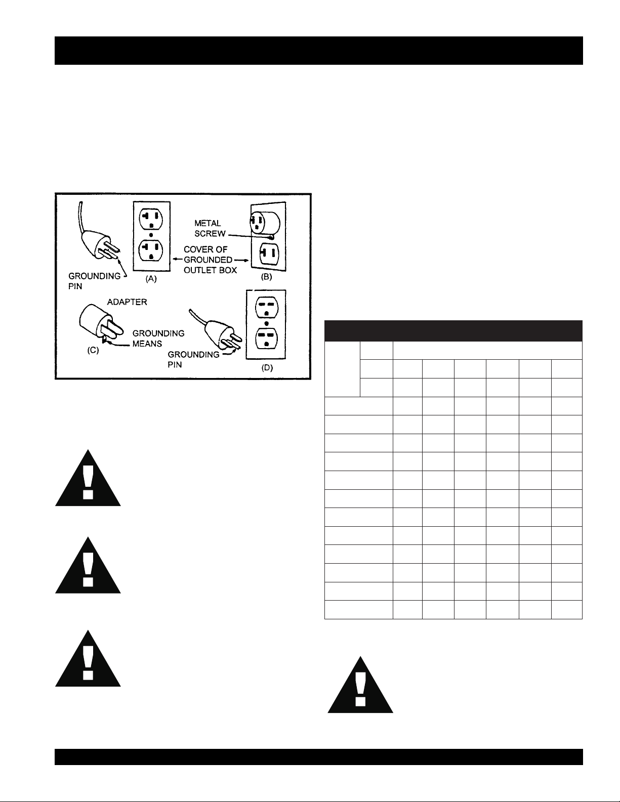
This concrete vibrator motor (230V) is equipped with a 3conductor cord, and a 3-prong grounding type plug to fit the
proper grounding type receptacle. The green conductor in
the cord is the ground wire. NEVER connect the green wire
to a live terminal. See (Figure 1) for proper grounding
methods. (230V ONLY)
Figure 1. Grounding Methods (230V) Typical
3. Use of extension cords.
■
MAKE CERTAIN the power cord/extension cord is free
from damage, and that the grounding circuit is
operational. Repair or replace all damaged cords and
grounding units.
■
When extending the cord, MAKE CERTAIN not to
submerge the connection in water. To avoid the
possiblility of electric shock, water-tight connections
should always be made.
■
Use only extension cords that are intended for outdoor
use and so marked.
■
Use only the gauge wire and length of cord
recommended for the motor size. If in doubt, go to the
next heavier gauge. (The smaller the gauge number,
the heavier the cord.)
■
See (Table 1) for recommended extension cord sizes.
stloV teeFnidroCfohtgneL
erepmA
gnitaR
egnaR
V511 .tF52 .tF05 .tF001 .tF051 .tF002 .tF052
V032 .tF05 .tF001 .tF002 .tF003 .tF004 .tF005
2-0 81 81 81 61 61 41
seziSdroCnoisnetxE.1ELBAT
WARNING!WARNING!
WARNING!
WARNING!WARNING!
WARNING!WARNING!
WARNING!
WARNING!WARNING!
WARNING!WARNING!
WARNING!
WARNING!WARNING!
DO NOT REMOVE THE GROUNDING PIN
FROM THE PLUG. (230V ONLY)
ALWAYS use a grounded 3-wire extension
cord that has a 3-prong grounding plug, and
a 3-pole receptacle that accepts the plug on
the concrete vibrator motor. (230V ONLY)
MAKE CERTAIN the motor is connected to a
GROUND FAULT CIRCUIT INTERRUPTER
to protect the operator from possible electric
shock. (230V ONLY)
CAUTION!CAUTION!
CAUTION!
CAUTION!CAUTION!
3-2 81 81 61 41 41 21
4-3 81 81 61 41 21 21
5-4 81 81 41 21 21 01
6-5 81 61 41 21 01 01
8-6 81 61 21 01 01 8
01-8 81 41 21 01 8 8
21-01 61 41 01 8 8 6
41-21 61 21 01 8 6 6
61-41 61 21 01 8 6 6
81-61 41 21 8 8 6 4
02-81 41 21 8 6 6 4
Use of an extension cord with a wire gauge
smaller than, or length longer than that stated
previously could result in reduced motor
performance and/or damage to the motor or
extension cord due to overheating.
SV-SERIES VIBRATOR MOTOR — PARTS & OPERATION MANUAL — REV. #2 (09/16/02) — PAGE 9
Page 10
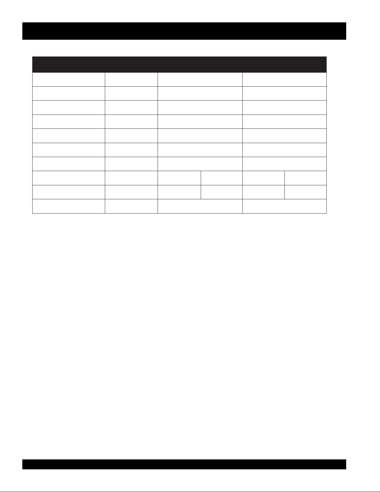
Specifications
ledoM 1-VS E2-VS/2-VS E3-VS/3-VS
rewopesroH PH1 PH2 PH3
htgneL "5.31 "5.31 "5.31
htdiW 57.8 "57.8 "57.8
thgieH "57.8 "57.8 "57.8
thgieW .SBL11 .SBL5.21 .SBL5.31
stloV CAV511 CAV511 CAV032 CAV511 CAV032
spmA A3-1 A5.3-2 A57.1-1 A5-3 A5.2-5.1
ztreH zH06 zH06 zH06
SV-SERIES VIBRATOR MOTOR— SPECIFICATIONS
SNOITACIFICEPS.2ELBAT
)daoLoN(MPR MPR000,81 MPR000,81 MPR000,81
PAGE 10 — SV-SERIES VIBRATOR MOTOR— PARTS & OPERATION MANUAL — REV. #2 (09/16/02)
Page 11
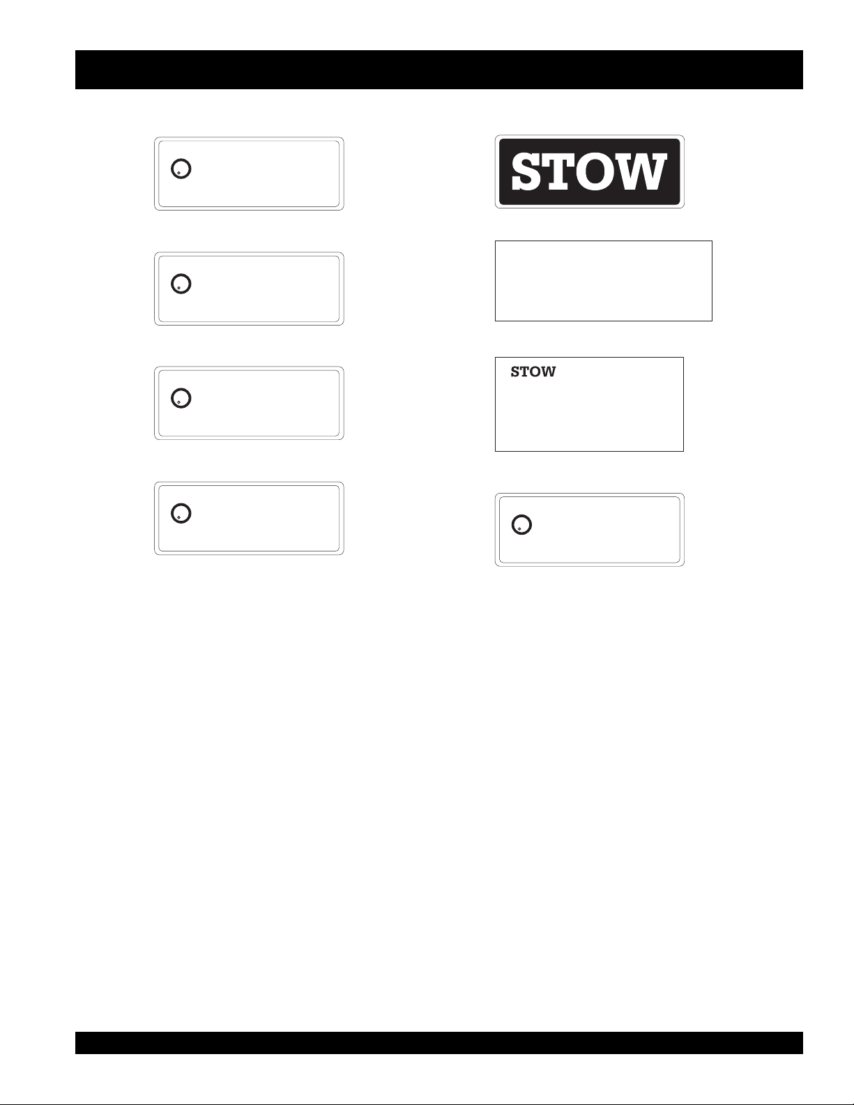
Machine Decals
U
L
C
LISTED
PORTABLE TOOL
31D0
US
SV-1
SV-1
DOUBLE INSULATED
SV-SERIES VIBRATOR MOTOR— DECALS
P/N 30166-001
U
L
US
C
SV-1
LISTED
SV-1
PORTABLE TOOL
31D0
U
L
C
LISTED
PORTABLE TOOL
31D0
U
L
C
LISTED
PORTABLE TOOL
31D0
US
US
HEAVY DUTY
P/N 30166-002
SV-2
SV-2
DOUBLE INSULATED
P/N 30166-004
SV-2
SV-2
HEAVY DUTY
P/N 30166-005
WARNING!
(SERIAL NUMBER TAG)
CONTACT SERVICE DEPARTMENT
U
L
US
C
SV-3
LISTED
PORTABLE TOOL
31D0
Figure 2. Decals, SV-1, SV-2 and SV-3
P/N 30242-001
WARNING!
P/N 20215-001
SV-3
HEAVY DUTY
P/N 30166-007
SV-SERIES VIBRATOR MOTOR — PARTS & OPERATION MANUAL — REV. #2 (09/16/02) — PAGE 11
Page 12
SV-SERIES VIBRATOR MOTOR—PREPARATION & OPERATION
Before using your Vibrator Motor, read and
fully understand all of the safety and
operating instructions not only for the motor,
but also for the flexible shafting and the head
that will be used with the motor.
1. The vibrator motor, flexible shafting, and heads are shipped
from the factory ready to use. Connect per instruction
bulletins.
2. Use only the combination of flexible shafting and heads
shown below in Table 3.
seziStfahS.3elbaT
LEDOM TFAHS EZISDAEH
1-VS V413
2-VS V283
3-VS V283
009
0001
0031
0041
0071
0012 .TF12
0041
0071
0012
0062
TFAHS.XAM
HTGNEL
.TF12
.TF82
.TF53
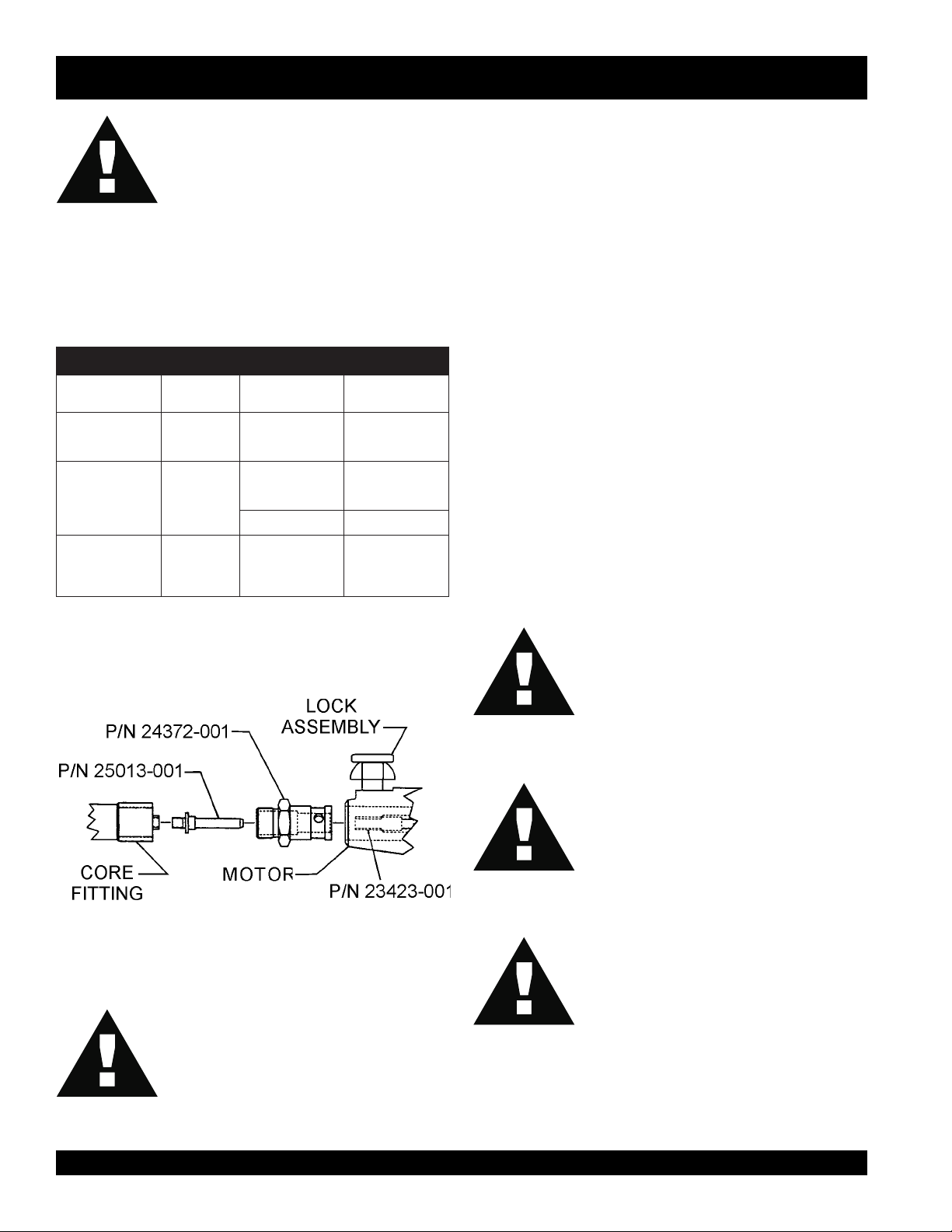
4. Slide the core out of the casing far enough to thread the
spindle (p/n 25013-001) into the core fitting and tighten. A
pair of pliers and a wrench can be used to tighten
theconnection. It is important that this connection be tight. If
it is not, the torque of the motor plus the load of the head will
jam the two fittings together making it extremely hard to
loosen them for disassembly.
5. Thread the shaft coupling (P/N 24372-001) into the casing
ferrule and tighten.
6. Pull up on the lock pin and slide the shaft assembly into the
front motor bearing housing and release the lock pin. Give
the shaft assembly a twist to make sure that the lock pin is
seated in one of the 3 tapered holes in the shaft coupling.
7. Clean the mating parts threads with Locquic Primer "T".
Allow to dry several minutes before applying a ring of Loctite
No. 271 or equivalent to the middle of thecasing threads.
Screw the head tightly to the casing and wait 1 hour before
using. Threads are left-hand; turn counter-clockwise to
tighten.
CAUTION!CAUTION!
CAUTION!
CAUTION!CAUTION!
3. To connect the 382V flexible shafting to the vibrator motor
see (Figure 3).
Figure 3. Shafting to Motor Connection
WARNING!WARNING!
WARNING!
WARNING!WARNING!
MAKE CERTAIN the motor is disconnected
from the power source and the switch is in the
"OFF" position.
CAUTION!CAUTION!
CAUTION!
CAUTION!CAUTION!
CAUTION!CAUTION!
CAUTION!
CAUTION!CAUTION!
If the shaft begins to helix (buckle) excessively
during operation, stop and investigate. This is
an indication of an overload condition.
The vibrator head is cooled by the concrete.
Operation of the vibrator head in air longer
than 2 minutes at a time will cause overheating
of the bearings which will result in premature
head failure.
Visually inspect the air intake and exhaust
frequently to make sure the motor has sufficient
air for cooling.
PAGE 12 — SV-SERIES VIBRATOR MOTOR— PARTS & OPERATION MANUAL — REV. #2 (09/16/02)
Page 13
SV-SERIES VIBRATOR MOTOR — OPERATION
THEORY OF CONCRETE VIBRATION
This
VIBRATOR MOTOR
concrete by removal of air pockets and voids.
The action of vibration is to set the particles in the fresh concrete
in motion, thereby reducing the friction between the particles
and giving the mixture the mobile quality of a thick fluid so that
gravity and the displacement of entrapped air will cause it to
settle easily into place.
is designed for the
compaction
of
By thus consolidating the concrete quickly, "stiffer" or "drier" mixes
can be poured than would otherwise be possible. It has been
proven that (up to a point) the drier the concrete, (that is, the less
water in it), the better the quality throughout and the greater the
strength.
Drier mixes also make the concrete more water tight, increase
resistance to weathering, and create a better bond between
daeH 009 0001 0031 0041 0071 0012 0062
concrete and reinforcement. Because vibration causes much of
the entrapped air in the concrete to rise to the surface,
honeycombing is prevented. Also, vibration eliminates most of
the air pockets between the concrete and the vertical forms.
7. Immerse the head for 5 to 10 seconds, (until air stops rising),
and then withdraw it slowly to let the concrete fill the void left
by the head.
SV-SERIES VIBRATOR MOTOR OPERATION
Read
all the safety instructions carefully. Safety instructions will
8. The head shoud be completely below the surface when
vibrating to keep the head cool.
be found throughout this manual and on the Vibrator Motor. Keep
all safety information in good, readable condition.
9. When vibrating a thin horizontal slab, the head can be used
in a horizontal position.
1. Make certain that the flexible shaft is properly attached to
the motor and the head to the flexible shaft.
2. Use the flexible shaft in as straight a position aspossible.
3. DO NOT bend the flexible shaft sharply at any point. Sharp
bends may cause a permanent kink, requiring early
replacement of the flexible shaft.
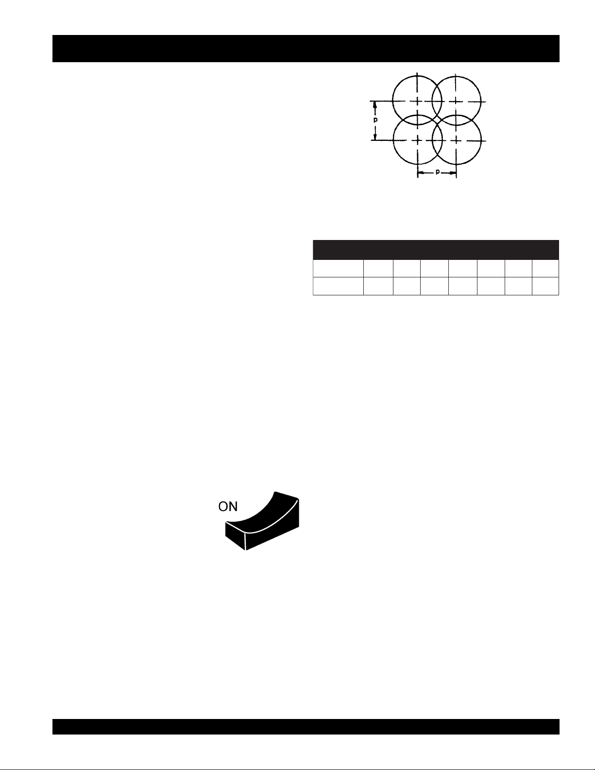
Figure 4. Compaction Coverage
with 50% Radial Overlap
egarevoCnoitcapmoC.4elbaT
noisnemiD-P "4 "2/1-5 "8 "8 "21 "41 "81
4. With the Stow vibrator motor properly
plugged into the correct power
source, turn the ON/OFF switch to
the "ON" position and proceed to
insert the vibrator into the cocrete.
5. The concrete is normally placed in the forms in layers about
12 to 18 inches thick in a manner which forms a fairly level
surface. The vibrator head is inserted vertically into the top
of the pile
.
6. DO NOT insert the head into the side of the pile to make the
concrete flow as this practice can cause segregation of the
aggregare from the motar. When the surface has become
fairly level, the head the should be immersed and generally
moved in the patter shown in Figure 4.
SV-SERIES VIBRATOR MOTOR — PARTS & OPERATION MANUAL — REV. #2 (09/16/02) — PAGE 13
Page 14
SV-SERIES VIBRATOR MOTOR — MAINTENANCE
MAINTENANCE
CAUTION!CAUTION!
CAUTION!
CAUTION!CAUTION!
Before performing any maintenace on this unit,
ALWAYS MAKE CERTAIN that the switch is
in the "OFF" position and the power cord is
disconnected from the power source.
This is a universal motor and it will run at approximately its rated
speed if the motor and its attached equipment are properly
operated and maintained.
1. Have repair work performed by an authorized service
facility, using identical or manufacturer approved
replacement parts.
2. This motor uses sealed bearings and does not require
lubrication.
3. Visually inspect the motor daily before use for defective or
missing parts, and have repairs made before use.
4. Inspect brushes frequently and replace when they become
worn to a length of 3/8".
5. Keep air inlet and air exit louvers clean and free of concrete
and debris. Failure to do so will result in rapid motor
overheating and parts failure.
6. Clean air filter as needed. If unit is used in high dust areas,
filter will have to be cleaned more often.
7. Use wrench to tighten brush caps. The brush cap must be
tight enough that the brush holder does not move.
8. Should complete disassembly of the motor become
necessary, it will be much easier if all internal components
are built into (Left) housing half P/N 29944-302. Using the
exploded view as a guide, place the anti-rotation pin side
of the field into the slot provided in the -302 housing. See
the end of the maintenance section for proper field
orientation. This anti-rotation pin along with the armature
bearing housings will help align the entire motor. Next,
place (Right) housing half P/N 29944-301 down on top of
the -302 half and snap them together, (the lip around the
housing should "pop" as it aligns). Holding the assembled
halves tightly, flip the entire unit over so that the screws can
be inserted.
10. Vibrator heads should be inspected and relubricated every
100 hours of operation. Follow the instructions for vibrator
heads.
Heat should be used to break down the loctite
while you unthread the head from the shaft.
This will prevent possible damage to the
threads from the loctite.
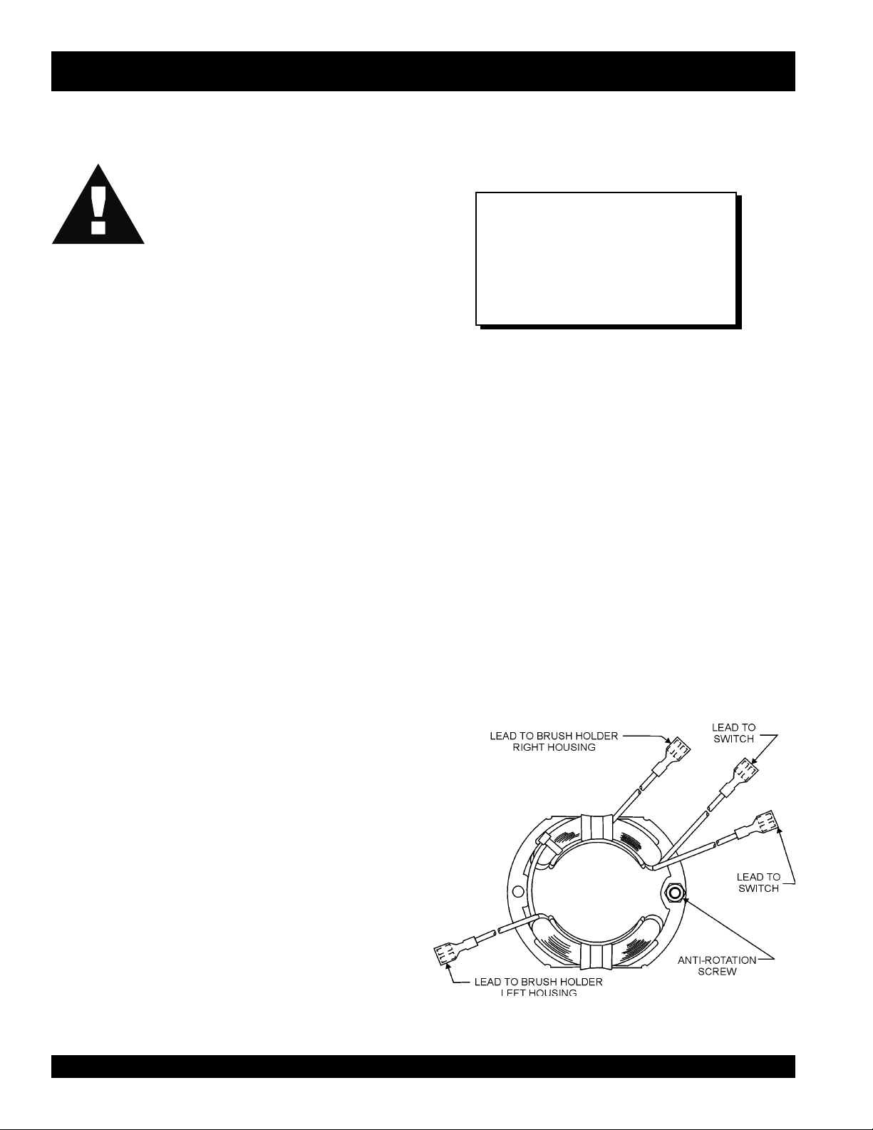
Field Orientation (Figure 5) (when viewed from the rear of
the motor)
1. The field should be positioned so the wires coming out of
the field are have 3 wires coming out of the upper field
shoe and one wire coming out of the lower field shoe.
2. The 2 long leads from the upper shoe should be routed
through the housing to the switch.
3. The third shorter lead from the upper shoe should be
connected to the right-hand brush holder when viewed
from the rear of the motor.
4. The single lead from the lower shoe should be connected
to the left -hand brush holder when viewed from the rear of
the motor.
5. After assembling complete motor, check the direction of
shaft rotation. When viewed from the front or drive end of
the motor the shaft should turn in a counter-clockwise
direction.
NOTE
Specification and part number
are subject to change without
notice.
9. The 382V flexible shaft requires cleaning and relubrication
every 100 hours of operation. Refer to 382V flexible shafting
operating instructions for maintenance instructions.
PAGE 14 — SV-SERIES VIBRATOR MOTOR— PARTS & OPERATION MANUAL — REV. #2 (09/16/02)
Figure 5. Field Orientation
Page 15
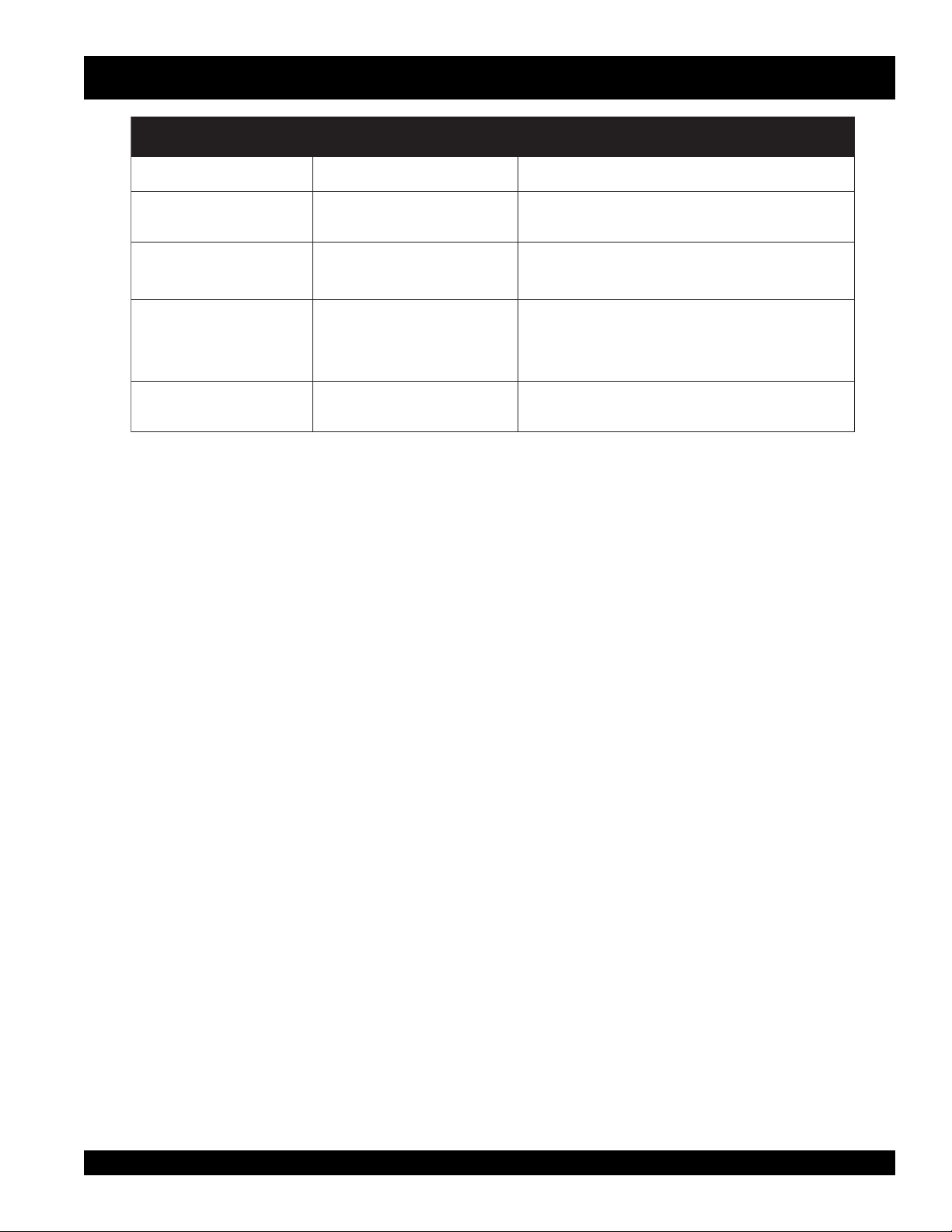
SV-SERIES VIBRATOR MOTOR — TROUBLESHOOTING
GNITOOHSELBUORT.5ELBAT
MOTPMYS MELBORPELBISSOP NOITULOS
.tratstonseodrotoM
ylreporprehtegot
.aera
taestonodsevlahgnisuoH
esiongniparcs/gnilworG
dleifdnaerutamramorf
drawrofmorfesiongnilttaR
.aeragnisuohgniraeb
.dlelif
.eriwdehcniP
.gnisuohsti
roenO.)erar(hctiwstuotnruB
.neposnoitcennoclanretnierom
dnaerutamraneewtebgnibbuR
.rerutcafunamehttcatnoc,detanimile
edisnigninnipsgniraebdrawroF
.dedeensasnoitcennocetelpmocroecalpeR
tonNIATRECEKAM.seriwtsujdaotrevirdwercsesU
.seriwehtnonoitalusniehtegamadot
.203-44992gnisuohnistnenopmocrotomelbmessaeR
gnibburrofleefdnasgniraebstinoerutamranipS
ebtonnacgnibburfI.erutamradnadleifehtneewteb
ro(906-CRetitcoLhtiwgniraebfognirretuoeruceS
.ecafrusgnisuohgniraebrenniehtot)tnelaviuqe
SV-SERIES VIBRATOR MOTOR — PARTS & OPERATION MANUAL — REV. #2 (09/16/02) — PAGE 15
Page 16
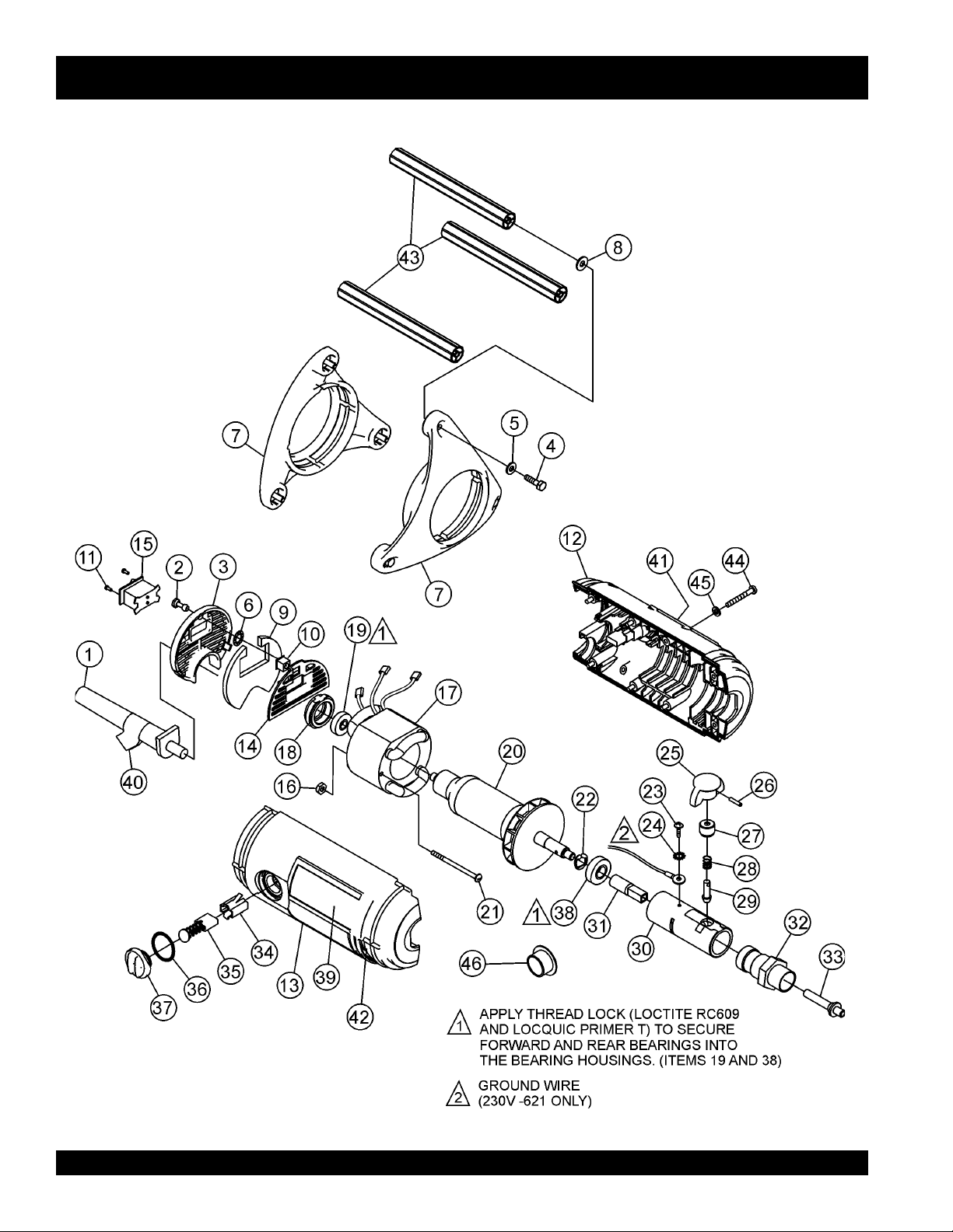
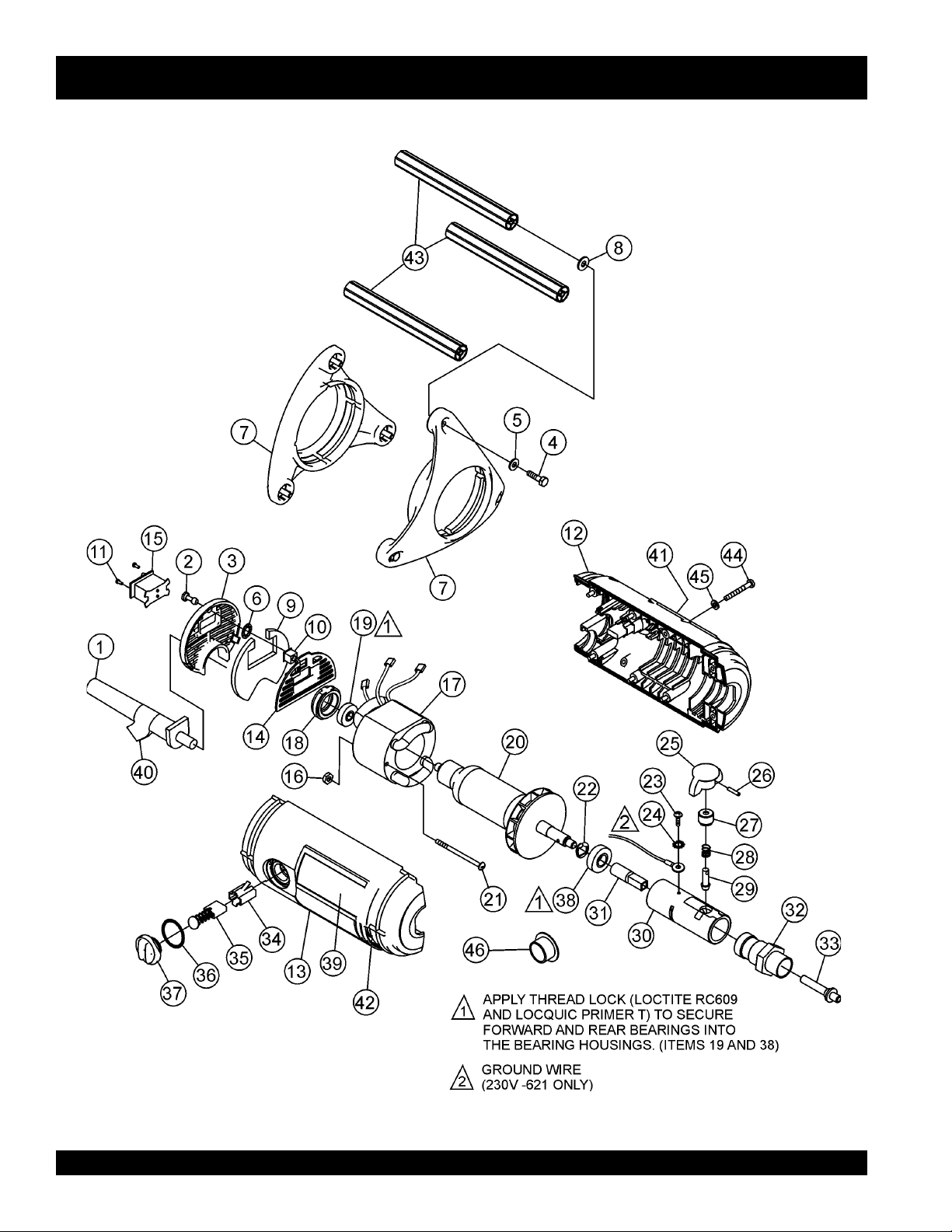
VIBRATOR MOTOR ASSY.
SV-SERIES — VIBRATOR MOTOR ASSY.
PAGE 16 — SV-SERIES VIBRATOR MOTOR— PARTS & OPERATION MANUAL — REV. #2 (09/16/02)
Page 17

SV-SERIES — VIBRATOR MOTOR ASSY.
VIBRATOR MOTOR ASSY.
NO. PART NO. PART NAME QTY. REMARKS
1 30205-401 CORD, 115V 1
1 30214-502 CORD, 230V 1
2 29982-001 STUD, FASTENER 1
3 29955-001 BACK PLATE 1
4 30190-016 SCREW, HHCS M6 X 16 6
5 30245-004 WASHER, FLAT 1/4" 6
6 30201-001 WASHER, RETAINER 1
7 29945-001 END CAP 2
8 10136 WASHER, FLAT 6
9 29980-001 AIR FILTER 1
10 29983-001 NUT, CAGE 1/4 TURN 1
11 15164-005 POP RIVET 2
12 29944-301 HOUSING, RIGHT 1
13 29944-302 HOUSING, LEFT 1
14 29954-001 PLATE, MTG SWITCH 1
15 23366-001 SWITCH 1
16 10019 NUT, NYLOC 1
17 29942-411 FIELD, 1HP 115V SV-1 1
17 29942-421 FIELD, 1HP 230V SV-1 1
17 29942-412 FIELD, 2HP 115V SV-2 1
17 29942-422 FIELD, 2HP 230V SV-2 1
17 29942-413 FIELD, 3HP 115V SV-3 1
17 29942-423 FIELD, 3HP 230V SV-3 1
18 29950-001 HOUSING, REAR BEARING 1
19 14611-001 BEARING, REAR 1
20 29943-411 ARMATURE, 1HP 115V SV-1 1
20 29943-421 ARMATURE, 1HP 230V SV-1 1
20 29943-412 ARMATURE, 2HP 115V SV-2 1
20 29943-422 ARMATURE, 2HP 230V SV-2 1
20 29943-413 ARMATURE, 3HP 115V SV-3 1
20 29943-423 ARMATURE, 3HP 230V SV-3 1
21 06827-044 SCREW, 10-32 X 2-3/4 1
22 10096-002 SNAP RING, EXT 1
23 16784-004 SCREW, 8-32 X 1/4 1
24 07027-013 WASHER, STAR #8 1
25 29946-001 KNOB 1
26 07502-016 ROLL PIN, 5/32 X 1 1
27 29948-001 HOUSING, SPRING 1
28 23432-001 SPRING 1
29 29947-001 PIN, QD LOCK 1
30 29949-001 HOUSING, FRONT BEARING 1
31 23429-001 FITTING, ADAPTER 1
32 29979-001 COUPLING, SHAFT 314V (SV-1) 1
32 24372-001 COUPLING, SHAFT 382V (SV-2 & SV-3) 1
33 29957-001 SPINDLE 314V (SV-1) 1
33 25013-001 SPINDLE 382V (SV-2 & SV-3) 1
OR ASSY.
SV-SERIES VIBRATOR MOTOR — PARTS & OPERATION MANUAL — REV. #2 (09/16/02) — PAGE 17
Page 18
VIBRATOR MOTOR ASSY.
SV-SERIES — VIBRATOR MOTOR ASSY.
PAGE 18 — SV-SERIES VIBRATOR MOTOR— PARTS & OPERATION MANUAL — REV. #2 (09/16/02)
Page 19

SV-SERIES — VIBRATOR MOTOR ASSY.
VIBRATOR MOTOR ASSY.
NO. PART NO. PART NAME QTY. REMARKS
34 23361-001 BRUSH HOLDER 2
35 30264-401 BRUSH ASM 2
36 22094-028 O-RING 2
37 29952-001 CAP, BRUSH 2
38 14611-003 BEARING, FRONT 1
39 30166-001 DECAL, SV-1 115V 1
39 30166-002 DECAL, SV-1 230V 1
39 30166-004 DECAL, SV-2 115V 1
39 30166-005 DECAL, SV-2 230V 1
39 30166-007 DECAL, SV-3 1
40 25215-001 DECAL, WARNING 1
41 30242-001 DECAL, STOW 1
42 TAG, SERIAL NUMBER ......................................... 1 ....... CONTACT SALES DEPT.
43 29951-001 TUBE HANDLE 3
44 29987-040 SCREW, M5 X 40MM 8
45 29988-005 WASHER, LOCK M5 8
46 11534-018 PROTECTOR, PLASTIC 1
SV-SERIES VIBRATOR MOTOR — PARTS & OPERATION MANUAL — REV. #2 (09/16/02) — PAGE 19
Page 20

Effective: July 1, 2000
TERMS AND CONDITIONS OF SALE
PAYMENT TERMS
Terms of payment for parts are net 10 days.
FREIGHT POLICY
All parts orders will be shipped collect or
prepaid with the charges added to the invoice.
All shipments are F.O.B. point of origin.
Multiquip’s responsibility ceases when a signed
manifest has been obtained from the carrier,
and any claim for shortage or damage must be
settled between the consignee and the carrier.
MINIMUM ORDER
The minimum charge for orders from Multiquip
is $15.00 net. Customers will be asked for
instructions regarding handling of orders not
meeting this requirement.
RETURNED GOODS POLICY
Return shipments will be accepted and credit
will be allowed, subject to the following
provisions:
1. A Returned Material Authorization must
be approved by Multiquip prior to shipment.
2. To obtain a Retur n Material Authorization,
a list must be provided to Multiquip Parts
Sales that defines item numbers,
quantities, and descriptions of the items to
be returned.
a. The parts numbers and descriptions
must match the current parts price
list.
b. The list must be typed or computer
generated.
c. The list must state the reason(s) for
the return.
d. The list must reference the sales
order(s) or invoice(s) under which
the items were originally purchased.
e. The list must include the name and
phone number of the person
requesting the RMA.
3. A copy of the Return Material
Authorization must accompany the return
shipment.
4. Freight is at the sender’s expense. All
5. Parts must be in new and resalable
6. The following items are not returnable:
7. The sender will be notified of any material
8. Such material will be held for 5 working
9. Credit on returned parts will be issued at
10. In cases where an item is accepted for
11. Credit issued will be applied to future
PRICING AND REBATES
parts must be returned freight prepaid to
Multiquip’s designated receiving point.
condition, in the original Multiquip package
(if any), and with Muiltiquip part numbers
clearly marked.
a. Obsolete parts. (If an item is listed
in the parts price book as being
replaced by another item, it is
obsolete.)
b. Any parts with a limited shelf life
(such as gaskets, seals, “O” rings,
and other rubber parts) that were
purchased more than six months
prior to the return date.
c. Any line item with an extended dealer
net price of less than $5.00.
d. Special order items.
e. Electrical components.
f. Paint, chemicals, and lubricants.
g. Decals and paper products.
h. Items purchased in kits.
received that is not acceptable.
days from notification, pending
instructions. If a reply is not received
within 5 days, the material will be returned
to the sender at his expense.
dealer net price at time of the original
purchase, less a 15% restocking charge.
which the original purchase document
can not be determined, the price will be
based on the list price that was effective
twelve months prior to the RMA date.
purchases only.
Prices are subject to change without prior
notice. Price changes are effective on a specific
date and all orders received on or after that date
will be billed at the revised price. Rebates for
price declines and added charges for price
increases will not be made for stock on hand at
the time of any price change.
Multiquip reserves the right to quote and sell
direct to Government agencies, and to Original
Equipment Manufacturer accounts who use
our products as integral parts of their own
products.
SPECIAL EXPEDITING SERVICE
A $20.00 to $50.00 surcharge will be added to
the invoice for special handling including bus
shipments, insured parcel post or in cases
where Multiquip must personally deliver the
parts to the carrier.
LIMITATIONS OF SELLER’S LIABILITY
Multiquip shall not be liable here under for
damages in excess of the purchase price of the
item with respect to which damages are claimed,
and in no event shall Multiquip be liable for loss
of profit or good will or for any other special,
consequential or incidental damages.
LIMITATION OF WARRANTIES
No warranties, express or implied, are made in
connection with the sale of parts or trade
accessories nor as to any engine not
manufactured by Multiquip. Such warranties
made in connection with the sale of new,
complete units are made exclusively by a
statement of warranty packaged with such
units, and Multiquip neither assumes not
authorizes any person to assume for it any
other obligation or liability whatever in
connection with the sale of its products. A part
from such written statement of warranty, there
are no warranties, express, implied or statutory,
which extend beyond the description of the
products on the face hereof.
PAGE 20 — SV-SERIES VIBRATOR MOTOR— PARTS & OPERATION MANUAL — REV. #2 (09/16/02)
Page 21
NOTE PAGE
SV-SERIES VIBRATOR MOTOR — PARTS & OPERATION MANUAL — REV. #2 (09/16/02) — PAGE 21
Page 22
PARTS AND OPERATION MANUAL
HERE'S HOW TO GET HELP
PLEASE HAVE THE MODEL AND SERIAL NUMBER
ON-HAND WHEN CALLING
PARTS DEPARTMENT
800-427-1244 or 310-537-3700
FAX: 800-672-7877 or 310-637-3284
SERVICE DEPARTMENT/TECHNICAL ASSISTANCE
800-478-1244 or 310-537-3700
FAX: 310- 537-4259
WARRANTY DEPARTMENT
888-661-4279, or 310-661-4279
FAX: 310- 537-1173
MAIN
800-421-1244 or 310-537-3700
FAX: 310-537-3927
STOW CONSTRUCTION EQUIPMENTSTOW CONSTRUCTION EQUIPMENT
STOW CONSTRUCTION EQUIPMENT
STOW CONSTRUCTION EQUIPMENTSTOW CONSTRUCTION EQUIPMENT
A DIVISION OF MULTIQUIP INC.
POST OFFICE BOX 6254
CARSON, CA 90749
310-537-3700 • 888-252-STOW [888-252-7869]
FAX: 310-537-1986 • FAX: 800-556-1986
E-MAIL: [email protected] • WWW: stowmfg.com
PARTS DEPARTMENT:
800-427-1244
FAX: 800-672-7877
SERVICE DEPARTMENT/TECHNICAL ASSISTANCE:
800-478-1244
FAX: 310-631-5032
 Loading...