

Page 1

OPERATION AND PARTS MANUAL
SERIES
MODEL
WBH-21EFP
POWER BUGGY
(B&S VANGUARD 18 HP PROPANE DRIVEN ELECTRIC START)
Revision #0 (03/06/18)
To find the latest revision of this
publication, visit our website at:
www.multiquip.com
THIS MANUAL MUST ACCOMPANY THE EQUIPMENT AT ALL TIMES.
Page 2
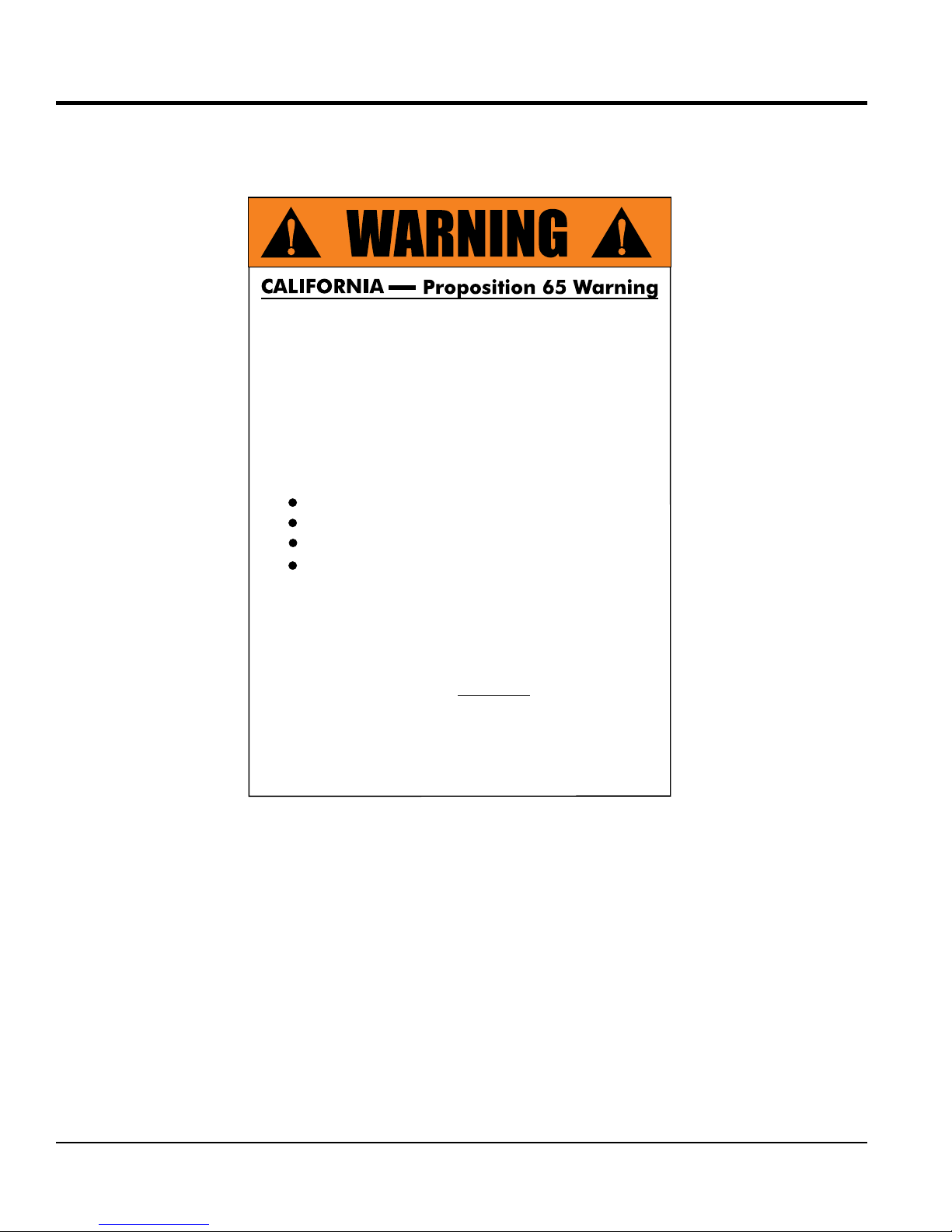
PROPOSITION 65 WARNING
Engine exhaust and some of
its constituents, and some dust created
of California to cause cancer, birth
defects and other reproductive harm.
by power sanding, sawing, grinding,
drillingandotherconstructionactivities
contains chemicals known to the State
Some examples of these chemicals are:
Leadfromlead-basedpaints.
Crystallinesilicafrombricks.
Cementandothermasonryproducts.
Arsenicandchromiumfromchemically
treatedlumber.
Your risk from these exposures varies,
dependingonhowoftenyoudo this type
of work. To reduce your exposure to
these chemicals: work in aALWAYS
well ventilated area, and work with
approved safety equipment, suchas
dust masks that are specially designed
to filter out microscopic particles.
PAGE 2 — WBH-21EFP POWER BUGGY • OPERATION AND PARTS MANUAL — REV. #0 (03/01/18)
Page 3

TABLE OF CONTENTS
WBH-21EFP POWER BUGGY
Proposition 65 Warning ........................................... 2
Table Of Contents .................................................... 3
Parts Ordering Procedures ...................................... 4
Safety Information .............................................. 5-11
Specifications (Buggy) ........................................... 12
Specifications (Engine) .......................................... 13
Dimensions ............................................................ 14
General Information ............................................... 15
Components .......................................................... 16
Basic Engine .......................................................... 17
Inspection ......................................................... 18-20
Operation .......................................................... 21-26
Maintenance ..................................................... 27-35
Troubleshooting ................................................ 36-38
Hydraulic System Diagram .................................... 39
Hydraulic Hose Connections ................................. 40
Engine Wiring Diagram .......................................... 41
Explanation Of Code In Remarks Column............. 42
Suggested Spare Parts ......................................... 43
Component Drawings
Nameplate And Decals Assembly. .................... 44-45
Hydraulic Drive Assembly ................................. 46-47
Hydraulic Pump Assembly ................................ 48-49
Hydraulic Dump Assembly ............................... 50-51
Pump And Coupling Assembly ......................... 52-53
Tub Assembly ................................................... 54-55
Panel Assembly ................................................ 56-57
Brake Assembly ................................................ 58-59
Steering And Controls Assembly ...................... 60-61
Chassis Assembly ............................................ 62-63
Handle/Foot Dump Controls Assembly............. 64-65
Hydraulic Oil Tank Assembly ............................ 66-67
Battery Assembly.............................................. 68-69
Carburetor Assembly ........................................ 70-71
Regulator And Vacuum Assembly .................... 72-73
Propane Tank Assembly ................................... 74-75
Engine Mounting Assembly .............................. 76-77
Engine Service Parts ........................................ 78-79
Terms And Conditions Of Sale — Parts ................ 80
NOTICE
Specifications and part numbers are subject to change
without notice.
WBH-21EFP POWER BUGGY • OPERATION AND PARTS MANUAL — REV. #0 (03/01/18) — PAGE 3
Page 4
www.multiquip.com
Ordering parts has never been easier!
If you have an MQ Account, to obtain a Username
parts@multiquip.
To obtain an MQ Account, contact your
Effective:
, 2006
PARTS ORDERING PROCEDURES
Choose from three easy options:
January 1
st
Best Deal!
Order via Internet (Dealers Only):
Order parts on-line using Multiquip’s SmartEquip website!
■ View Parts Diagrams
■ Order Parts
■ Print Specification Information
Goto www.multiquip.com and click on
Order Parts
to log in and save!
Order via Fax (Dealers Only):
All customers are welcome to order parts via Fax.
Domestic (US) Customers dial:
1-800-6-PARTS-7 (800-672-7877)
Order via Phone:
Non-Dealer Customers:
Contact your local Multiquip Dealer for
parts or call 800-427-1244 for help in
locating a dealer near you.
Domestic (US) Dealers Call:
1-800-427-1244
Use the internet and qualify for a 5% Discount
on Standard orders for all orders which include
complete part numbers.*
Fax your order in and qualify for a 2% Discount
on Standard orders for all orders which include
complete part numbers.*
International Customers should contact
their local Multiquip Representatives for
Parts Ordering information.
and Password, E-mail us at:
com.
District Sales Manager for more information.
Note: Discounts Are Subject To Change
Note: Discounts Are Subject To Change
PAGE 4 — WBH-21EFP POWER BUGGY • OPERATION AND PARTS MANUAL — REV. #0 (03/01/18)
When ordering parts, please supply:
❒ Dealer Account Number
❒ Dealer Name and Address
❒ Shipping Address (if different than billing address)
❒ Return Fax Number
❒ Applicable Model Number
❒ Quantity, Part Number and Description of Each Part
NOTICE
All orders are treated as Standard Orders and will
ship the same day if received prior to 3PM PST.
WE ACCEPT ALL MAJOR CREDIT CARDS!
❒ Specify Preferred Method of Shipment:
✓ UPS/Fed Ex ✓ DHL
■ Priority One ✓ Tr uck
■ Ground
■ Next Day
■ Second/Third Day
Page 5
SAFETY INFORMATION
Do not operate or service the equipment before reading
the entire manual. Safety precautions should be followed
at all times when operating this equipment.
Failure to read and understand the safety
messages and operating instructions could
result in injury to yourself and others.
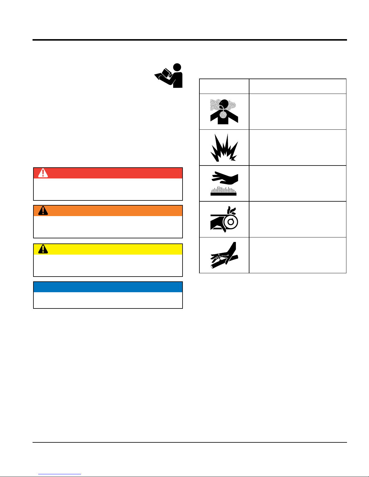
SAFETY MESSAGES
The four safety messages shown below will inform you
about potential hazards that could injure you or others. The
safety messages specifi cally address the level of exposure
to the operator and are preceded by one of four words:
DANGER, WARNING, CAUTION
SAFETY SYMBOLS
Potential hazards associated with the operation of this
equipment will be referenced with hazard symbols which
may appear throughout this manual in conjunction with
safety messages.
or NOTICE.
DANGER
Indicates a hazardous situation which, if not avoided,
WILL result in DEATH or SERIOUS INJURY.
WARNING
Indicates a hazardous situation which, if not avoided,
COULD result in DEATH or SERIOUS INJURY.
CAUTION
Indicates a hazardous situation which, if not avoided,
COULD result in MINOR or MODERATE INJURY.
Symbol Safety Hazard
Lethal exhaust gas hazards
Explosive fuel hazards
Burn hazards
Rotating parts hazards
Hydraulic fluid hazards
NOTICE
Addresses practices not related to personal injury.
WBH-21EFP POWER BUGGY • OPERATION AND PARTS MANUAL — REV. #0 (03/01/18) — PAGE 5
Page 6
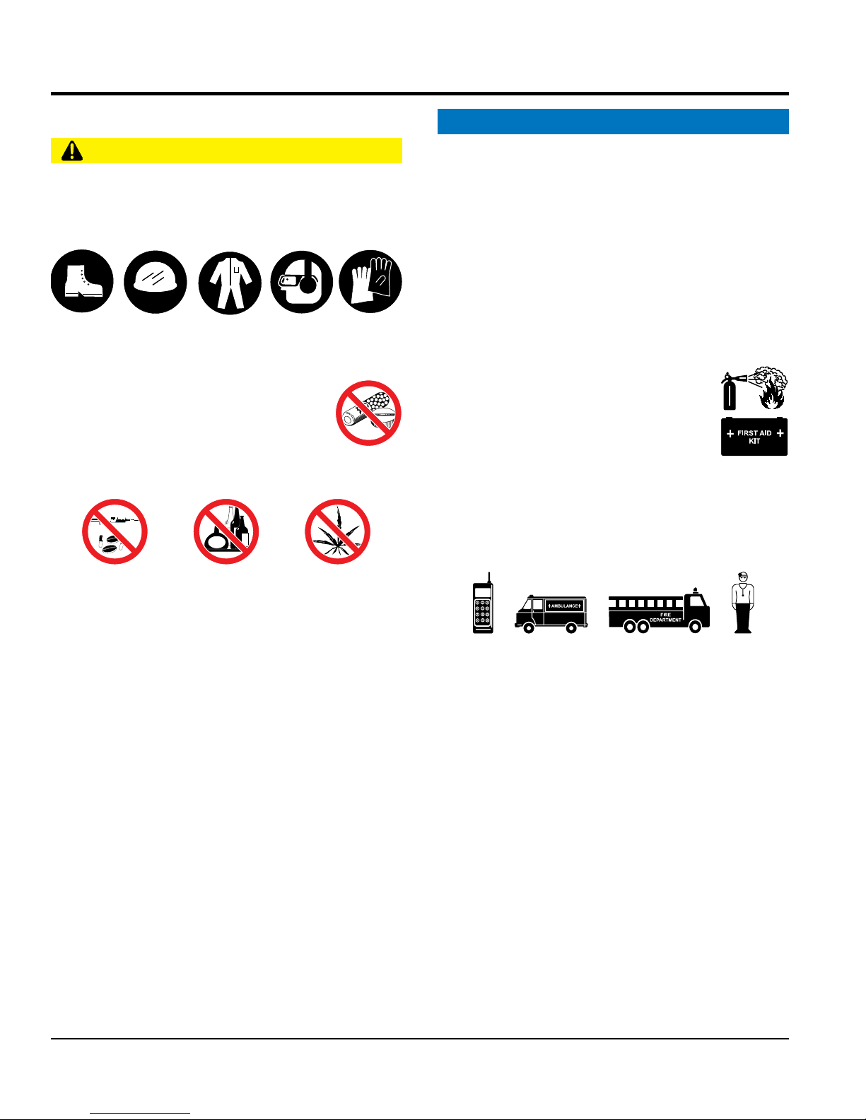
GENERAL SAFETY
NOTICE
This equipment should only be operated by trained and
Whenever necessary, replace nameplate, operation and
Manufacturer does not assume responsibility for any
accident due to equipment modifi cations. Unauthorized
use accessories or attachments that are not
recommended by Multiquip for this equipment. Damage
keep
Also, know the phone numbers
fi re department.
This information will be invaluable in the case of an
SAFETY INFORMATION
CAUTION
NEVER operate this equipment without proper protective
clothing, shatterproof glasses, respiratory protection,
hearing protection, steel-toed boots and other protective
devices required by the job or city and state regulations.
Avoid wearing jewelry or loose fi tting clothes that may
snag on the controls or moving parts, as this can cause
serious injury.
NEVER operate this equipment when not
feeling well due to fatigue, illness, or when
using medication.
NEVER operate this equipment under the
infl uence of drugs or alcohol.
ALWAYS clear the work area of any debris, tools, etc.
that would constitute a hazard while the equipment is
in operation.
No one other than the operator is to be in the working
area when the equipment is in operation.
DO NOT use the equipment for any purpose other than
its intended purposes or applications.
qualifi ed personnel 18 years of age and older.
safety decals when they become diffi cult read.
equipment modifi cation will void all warranties.
NEVER
to the equipment and/or injury to the user may result.
ALWAYS know the location of the nearest
fi re extinguisher.
ALWAYS know the location of the nearest
fi rst aid kit.
ALWAYS know the location of the nearest phone or
a phone on the job site.
of the nearest ambulance, doctor and
emergency.
PAGE 6 — WBH-21EFP POWER BUGGY • OPERATION AND PARTS MANUAL — REV. #0 (03/01/18)
Page 7
SAFETY INFORMATION
POWER BUGGY SAFETY
inspect the surface over which you will travel.
Look for holes, drop-offs, and obstacles. Look for rough
and weak spots on docks, ramps or fl oor. Look for oil
spills, wet spots, and slippery surfaces. Look for soft
soil, deep mud, and standing water. Watch for anything
that might make you lose control or cause the power
clear away trash and debris. Pick up anything
make sure aisles, ramps, doorways and
plan your work. Make sure you know where
you will make your pickups, dumps and turns. Before
operate the power buggy on unsafe haul roads,
operate the power buggy on excessive slopes
with a grade higher than 10% (6°), forward and backward.
operate the power buggy on extremely uneven
allow riders other than the operator on the
secure the step plate (platform) in the upright
position when using the power buggy over rough terrain.
stand on the power buggy step plate (platform)
when walking in rough terrain. Walk behind the power buggy.
touch, lean on, or reach through the dump
climb on
CAUTION
DANGER
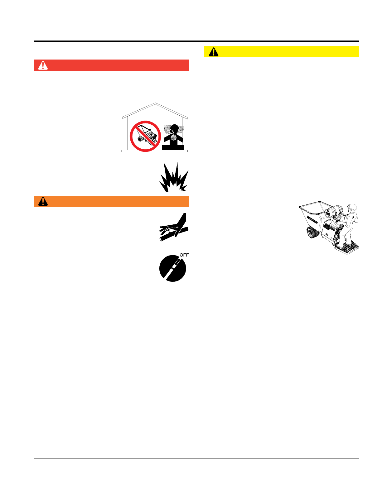
Engine fuel exhaust gases contain poisonous carbon
monoxide. This gas is colorless and odorless, and can
cause death if inhaled.
Operate equipment only in
areas with adequate
ventilation. NEVER operate
in confined areas, or in
areas where the free fl ow of
air is restricted.
NEVER operate the equipment in an explosive
atmosphere or near combustible materials. An
explosion or fi re could result, causing severe
bodily harm or even death.
WARNING
NEVER use your hand to fi nd hydraulic leaks.
Use a piece of wood or cardboard. Hydraulic
fl uid injected into the skin must be treated by
a knowledgeable physician immediately or
severe injury or death can occur.
Accidental starting can cause severe injury
or death. ALWAYS place the ON/OFF
switch in the OFF position.
NEVER disconnect any emergency or safety devices.
These devices are intended for operator safety.
Disconnection of these devices can cause severe injury,
bodily harm or even death. Disconnection of any of
these devices will void all warranties.
NEVER approach power lines with any part of the
buggy unless all local, state/provincial and federal
(OSHA) required safety precautions have been taken.
Use extreme caution when approaching high voltage
power lines.
ALWAYS
DANGEROUS
GAS FUMES
buggy to tip over.
ALWAYS
that might puncture the tires.
ALWAYS
passages are clear.
ALWAYS
you take a load, know where you will place it.
NEVER operate the power
buggy facing backwards. In
a backwards position, the
operator cannot properly grip
the handles, steer the machine,
or activate the manual brake or
emergency switch. ALWAYS
face in the direction of the
bucket.
DO NOT
load areas, or dump areas.
DO NOT
DO NOT
surfaces.
NEVER
power buggy.
ALWAYS
WBH21EFP
WBH-21EFP POWER BUGGY • OPERATION AND PARTS MANUAL — REV. #0 (03/01/18) — PAGE 7
DO NOT
DO NOT
mechanism or permit others to do so. NEVER
the power buggy or dump mechanism.
Page 8

SAFETY INFORMATION
DO NOT operate the power buggy at excessive speeds.
ALWAYS block the power buggy with appropriate blocks
start the
Ensure that the speed control lever works freely and
start the engine
Make sure the tires are infl ated to the manufacturer’s
operate the power buggy with bad or worn tires.
make sure the hydraulic dumping mechanism
Avoid sudden stops and starts and changes in direction.
jerk the steering
attempt to work the controls except from the
drive or tow the power buggy in traffi c or on
Fix damage to the machine and replace any broken
The entire power buggy (tub, step plate, shroud, wheels, etc.)
should be cleaned after every use. Make sure there is no
buildup of concrete, grease, oil, or debris on the machine.
store equipment properly when it is not being
used. Equipment should be stored in a clean, dry location
out of the reach of children and unauthorized personnel.
position
Reckless operation may cause accidents and severe
injury. Slow down when approaching people, wet areas,
and going up and down grades. It is the responsibility of
the operator to adjust speed, as necessary, depending
on the conditions of the road or path.
ALLOW extra time to stop when operating the power
buggy on wet surfaces or loosely graded materials.
DO NOT dump materials that are large and chunky.
These types of material may shift, causing the power
buggy to tip and throw the operator off the machine. The
power buggy is intended for dumping free-fl owing and
loose materials such as dry soil, slag, and wet concrete.
DO NOT dump materials from the bucket while the power
buggy is moving.
For walk-behind operation, the operator platform must be
stowed and locked in the up position. The speed should
also be reduced to 3 mph (4.8 kph) or slower.
NOTICE
ALWAYS ensure the power buggy is securely placed
on appropriate blocks or jackstands when maintenance
requires elevation of the buggy.
ALWAYS make sure the power buggy’s brakes are
working properly. Check the brake linkage and adjust
as required. NEVER operate the power buggy with a
defective braking system.
when leaving the power buggy parked on a slope.
To prevent unexpected loss of control, DO NOT
engine on a sloping surface.
returns to the closed position. DO NOT
unless the speed control linkage is working properly.
recommended tire pressure.
NEVER
ALWAYS replace defective tires with new ones.
ALWAYS
of the tub is working properly.
Operate the controls smoothly. DO NOT
or any other controls.
NEVER
operator’s position.
NEVER
public roads.
ALWAYS keep the machine in proper running condition.
parts immediately.
Ensure brakes are applied when using on a slope.
When parking on a slope, position the power buggy at
a right angle to a slope. Ensure that the parking brake
is engaged and holds the power buggy safely in place
when parking on a slope.
When fi lling or dumping, DO NOT exceed the payload
capacity of the power buggy.
ALWAYS be aware of traveling conditions. Reduce load
if necessary.
DO NOT activate the dump mechanism (tub) if the buggy
is facing a downhill slope.
DO NOT stand in front of or along side the buggy when
discharging a load.
PAGE 8 — WBH-21EFP POWER BUGGY • OPERATION AND PARTS MANUAL — REV. #0 (03/01/18)
ALWAYS
ALWAYS place the fuel valve lever in the OFF
when the equipment is not in use.
Page 9
SAFETY INFORMATION
ENGINE SAFETY
FUEL SAFETY (LPG/PROPANE)
use extreme caution when handling propane.
and can cause
if not handled
fi ll propane tank within 25 feet (7.62 meters) of
buildings and adjoining structures that may be a source
Remove all combustible materials including dry grass
and leaves within 25 feet (7.62 meters) of the LPG
Before filling, visually inspect the propane tank for
fi ll the
propane tank if it is damaged, corroded, displays leaks
fi ll the propane tank if the pressure relief or fi ll
in a well-ventilated
area, away from sparks and open fl ames. LP gas is
fi ll the propane tank while the engine is running
Accumulation of LP gas vapors may result in the
development of an oxygen-defi cient atmosphere which
enter a gas cloud area. This condition produces
LPG/propane storage locations should be equipped with
at least one approved portable fi re extinguisher that has
a minimum capacity of 18 lb. dry chemical with a B:C
use carbon-tetrachloride extinguishers
WARNING
DO NOT place hands or fi ngers inside the
engine compartment when the engine is
running.
NEVER operate the engine with heat shields or
guards removed.
Keep fi ngers, hands, hair, and clothing away
from all moving parts to prevent injury.
ALWAYS shut down the engine before
performing service or maintenance.
DO NOT remove the engine oil drain plug while the
engine is hot. Hot oil will gush out of the oil tank and
severely scald any persons in the general area of the
power buggy.
CAUTION
NEVER touch the hot exhaust manifold,
muffl er or cylinder. Allow these parts to cool
before servicing the equipment.
DANGER
ALWAYS
Propane is fl ammable and explosive
serious personal injury or death
properly.
DO NOT
of ignition.
dispenser.
dents, cracks, and excessive corrosion. NEVER
at fi ttings\valves, or contains foreign material.
NEVER
valves are damaged.
ALWAYS fi ll the propane tank outdoors
Make certain the operator knows how to and is capable
of turning the engine OFF in case of an emergency.
NOTICE
NEVER run the engine without an air fi lter or with a dirty
air fi lter. Severe engine damage may occur. Service the
air fi lter frequently to prevent engine malfunction.
NEVER tamper with the factory settings
of the engine or engine governor. Damage
to the engine or equipment can result
if operating in speed ranges above the
maximum allowable.
odorless and invisible.
DO NOT
or hot.
DO NOT smoke around or near the
equipment. Fire or explosion could result
from gas vapors.
carries a risk of asphyxiation.
NEVER
an oxygen-defi cient atmosphere that could be fatal.
rating. DO NOT
such as pyrene.
NEVER check for leaks using an open fl ame.
WBH-21EFP POWER BUGGY • OPERATION AND PARTS MANUAL — REV. #0 (03/01/18) — PAGE 9
Page 10
SAFETY INFORMATION
CAUTION
BATTERY SAFETY
DO NOT charge the battery if frozen. The battery can
. When frozen, warm the battery to at least
recharge the battery in a well-ventilated
environment to avoid the risk of a dangerous concentration
If the battery liquid (dilute sulfuric acid) comes into
, rinse eyes immediately with plenty
of water and contact the nearest doctor or hospital to
battery terminal
keep battery cables in good working condition.
allow any person or animal to stand underneath
When lifting of the power buggy is required, use a
properly rated forklift. Forklift pockets are provided on
the power buggy's frame. Make sure the forklift arms are
insert into the power buggy's forklift pockets a minimum
of 24 inches. Before lifting, make sure that the lifting bail
tip the engine to extreme angles during lifting
as this may cause oil to gravitate into the cylinder head,
use ramps capable of supporting the weight
the operator to load and unload
NEVER use propane tanks that are fi lled beyond 80%
capacity.
The propane tank must be fi lled by a trained propane
filling station attendant or someone who has been
offi cially trained by a propane fuel provider.
ALWAYS use protective gloves when handling the
propane tank. LP gas will cause cold burns if it comes
into contact with the skin.
The eyes and body must be protected when handling all
LP gas products. ALWAYS wear protective eye safety
glasses and clothing.
LP gas is heavier than air. An underground or low level
leak might not be detected immediately.
NOTICE
Only use propane when operating this equipment.
NEVER use any other type of fuel including diesel or
methanol as serious damage to the engine will occur.
Consult the National Fire Protection Association (NFPA)
handbook for the handling, storing, transporting and
useage of propane fuel.
DANGER
DO NOT drop the battery. There is a possibility that the
battery will explode.
DO NOT expose the battery to open fl ames,
sparks, cigarettes, etc. The battery contains
combustible gases and liquids. If these
gases and liquids come into contact with a
fl ame or spark, an explosion could occur.
WARNING
ALWAYS wear safety glasses when
handling the battery to avoid eye irritation.
The battery contains acids that can cause
injury to the eyes and skin.
Use well-insulated gloves when picking up
the battery.
ALWAYS keep the battery charged. If the battery is not
charged, combustible gas will build up.
explode
61°F (16°C).
ALWAYS
of combustible gases.
If the battery liquid (dilute sulfuric acid)
comes into contact with clothing or skin,
rinse skin or clothing immediately with
plenty of water.
contact with eyes
seek medical attention.
CAUTION
ALWAYS disconnect the NEGATIVE
before performing service on the equipment.
ALWAYS
Repair or replace all worn cables.
LIFTING SAFETY
NEVER
the equipment while lifting.
NOTICE
is not damaged.
NEVER
making it diffi cult to start the engine.
DO NOT lift the machine to unnecessary heights.
NEVER lift the equipment while the engine is running.
ALWAYS
of the power buggy and
the power buggy.
CAUTION
PAGE 10 — WBH-21EFP POWER BUGGY • OPERATION AND PARTS MANUAL — REV. #0 (03/01/18)
Page 11

SAFETY INFORMATION
TRANSPORTING SAFETY
ENVIRONMENTAL SAFETY/
Decommissioning is a controlled process used to safely
retire a piece of equipment that is no longer serviceable.
If the equipment poses an unacceptable and unrepairable
safety risk due to wear or damage or is no longer cost
effective to maintain (beyond life-cycle reliability) and is to
be decommissioned (demolition and dismantlement), be
sure to follow the rules below.
When the life cycle of this equipment is over, it is
recommended that the unit frame and all other metal
Metal recycling involves the collection of metal from
discarded products and its transformation into raw
materials to use in manufacturing a new product.
Recyclers and manufacturers alike promote the process
of recycling metal. Using a metal recycling center
The emission control label is an integral part of the emission
If a replacement emission label is needed, please contact
NOTICE
ALWAYS shut down the engine before transporting.
ALWAYS place the propane tank shut-off valve in the
OFF position.
When transporting of the power buggy is required, place
the power buggy on a fl atbed truck or equivalent and tie
down securely.
ALWAYS make sure all tie-downs and blocks are in
place, and the bucket is completely lowered in the fl at
(horizontal) position and securely latched.
Place chock blocks underneath the wheels to prevent
rolling.
When transporting the power buggy on a truck or trailer,
know the overall height to avoid contacting overhead
obstructions such as bridges and power lines. Check
the truck and ramp capacities.
DECOMMISSIONING
parts be sent to a recycling center.
promotes energy cost savings.
EMISSIONS INFORMATION
NOTICE
Emission Control Label
system and is strictly controlled by regulation(s).
The label must remain with the engine for its entire life.
your authorized engine distributor.
NOTICE
DO NOT pour waste or oil directly onto the ground, down
a drain or into any water source.
Contact your country's Department of
Public Works or recycling agency in your
area and arrange for proper disposal of
any electrical components, waste, or oil
associated with this equipment.
When the life cycle of this equipment is over, remove
the battery (if equipped) and bring it to an appropriate
facility for lead reclamation. Use safety precautions when
handling batteries that contain sulfuric acid.
WBH-21EFP POWER BUGGY • OPERATION AND PARTS MANUAL — REV. #0 (03/01/18) — PAGE 11
Page 12

SPECIFICATIONS (BUGGY)
Table 1. Specifications (Power Buggy)
Model WBH-21EFP
Maximum Weight Capacity
(Dual Wheels)
Operating Weight 1,492 lbs. (677 kg.)
Bucket/Tub Capacity 21 cu. ft. Water Level (.78 cu. yd.)
Bucket/Tub Material Polyethylene
Drive Hydrostatic
Speed Up to 7.25 mph. (11.67 km/h)
Steering Handle Bars To Rear Wheels
Propane Vapor Tank Capacity
Hydraulic Oil Tank Capacity 5.3 gallons (20.4 liters)
Hydraulic Oil Type Exxon/Mobil Nuto H 46 or Equivalent.
Hydraulic Filter 200 Micron Mesh
Brakes (Drive Wheels) Dynamic Hydrostatic
Parking Brake (Drive Wheels) Mechanical
Dump Control Hydraulic Dump and Return
Discharge Height 6.0 in. (152 mm)
Ground Clearance 6.0 in. (152 mm)
Fill to 80% Capacity 26.8 lbs. (12.1 kg/29.04 liters)
3,200 lbs. (1,451 kg)
33.5 lbs. (15.2 kg/36.3 liters)
Gradeability 6°
12V BCI Group U1, 300 CCA @ 0°F
Battery (LxWxH)
Foam Filled Tires (Drive Wheels)
Foam Filled Tires (Steering)
PAGE 12 — WBH-21EFP POWER BUGGY • OPERATION AND PARTS MANUAL — REV. #0 (03/01/18)
7.75 x 5.18 x 7.31 in.
(197 x 132 x 186 mm)
5.70 x 8.0
(145 x 203 x 483 mm)
4.80 x 8.0 in.
(122 x 203 mm)
Page 13

SPECIFICATIONS (ENGINE)
Table 2. Specifications (Engine)
Model Briggs and Stratton Vanguard
Type Twin Cylinder, Overhead Valve, Air Cooled
Bore X Stroke 2.82 x 2.75 in. (71.88 x 69.85 mm)
Displacement 34.7 cu. in. (570 cc)
Maximum Power 18.0 hp (3,600 rpm)
Maximum Torque
Idle Speed 1,400 ± rpm
Maximum No Load RPM 3600 ± 100 rpm
Specific Fuel Consumption 1.64 gals./hr. (6.05 liters/hr.)
Fuel Type HD-5 or HD-10 Liquid Propane
Oil Type API Service Class SF, SG, SH, SJ or Higher
Oil Filter Spin-On
Crankcase Oil Capacity 1.8 quarts (1.7 Liters)
Starting System Recoil/Electric
Spark Plug Gap 0.028 - 0.031 in. (0.70 - 0.76 mm)
Air Cleaner Dual Element
Dry Weight 74.0 lbs. (33.56 kg.)
Outside Dimensions L X W X H
31.70 ft-lbs. (2,800 rpm)
14.37 kgf-m (2,800 rpm)
17.40 x 10.60 x 18.14 in.
(439 x 406 x 344 mm)
WBH-21EFP POWER BUGGY • OPERATION AND PARTS MANUAL — REV. #0 (03/01/18) — PAGE 13
Page 14
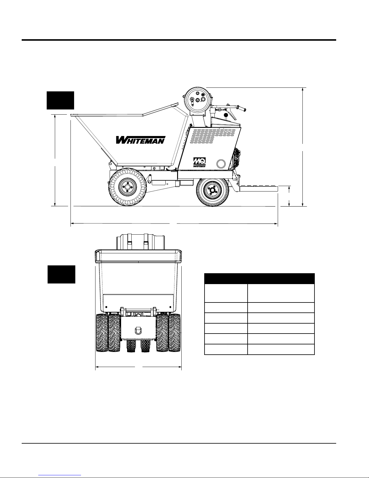
SIDE
VIEW
A
DIMENSIONS
B
WBH-21EFP
C
FRONT
VIEW
D
Table 3. Dimensions
Reference
Letter
Dimension
in. (mm)
A 45.47 (1,155)
B 51.0 (1,295)
C 8.50 (216)
D 103 (2,612)
E 44 (1,117)
E
PAGE 14 — WBH-21EFP POWER BUGGY • OPERATION AND PARTS MANUAL — REV. #0 (03/01/18)
Figure 1. WBH21-EFP Dimensions
Page 15
GENERAL INFORMATION
The MQ Whiteman Power Buggy, Model WBH-21EFP
(recoil/electric start) is intended for the transportation of
concrete, concrete spreading and spot pouring. In addition,
this power buggy is designed for landscaping applications,
material sub-base distribution, job site cleanup and material
transport.
The Power Buggy is equipped with a 6-inch dump height
which provides clearance and enables the operator to
maneuver over any form height. In addition, it has a unique
polyethylene tub design that reduces concrete splatter.
A low center of gravity has been incorporated into the
design which provides added safety when maneuvering
the buggy in tight areas. A 7.5 gallon (28.3 liters) propane
fuel tank allows for extended uninterrupted use. Maximum
speed of the power buggy is rated at 7.25 mph (11.7 km/h).
The maximum weight capacity of the Power Buggy is
3,200 lbs. (1,451 kg).
Hand and foot controls are provided for ease of dumping
and stopping of the power buggy. Multiple lift points have
been provided to allow for easy access of a forklift when
lifting is required.
The WBH-21EFP is powered by a Briggs and Stratton
Vanguard twin cylinder, air cooled engine rated at 18 HP
at 3600 RPM.
The engine drives a variable displacement hydrostatic
transmission which is activated by a cable controlled
hand lever. The hydraulic fluid flows to a divider valve
which directs the fluid to the forward reverse and dumping
systems.
The operator controls the forward and reverse machine
travel by manually shifting the control valve which directs
the hydraulic fluid flow to the two drive wheel motors. The
flow to the dump cylinder is also controlled by a manually
operated control valve.
This hydraulic system uses a parallel loop configuration,
operating at a maximum of 2100 PSI (14,478 kPa). The
system also features a neutral position which allows the
power buggy to be moved in the event of an emergency.
The hydraulic oil is filtered by a screen type filter located in
the hydraulic tank, then doubled filtered within the system
by a 10 micron cartridge spin-on return filter.
WARNING
All operators must have training before operating the
power buggy. For your safety, warnings are on the
machine and in this manual. Failure to obey these
warnings can cause severe injury or even death.
CAUTION
This engine has been designed to use a special vapor
propane tank that is specifically designed for vapor run
small engine applications.
DO NOT attempt to operate the power
buggy until the Safety Information, General
Information, and Inspection sections of this
manual have been read and thoroughly
understood.
WBH-21EFP POWER BUGGY • OPERATION AND PARTS MANUAL — REV. #0 (03/01/18) — PAGE 15
Page 16
COMPONENTS
1
2
3
17
21
20
WBH21EFP
19
18
Figure 2. WBH21-EF Power Buggy Components
16
15
4
14
5
6
7
8
9
10
11
12
13
1. Tub or Bucket — Used for the transportation of
material. Tub holds approximately 21 cubic feet
(0.59 cubic yards) of water.
9. Parking Brake Lever — When this lever is activated
(pulled up), the parking brake will be set. To release
the brake, pull the lever downwards.
10. Hydraulic Tank/Cap — Remove this cap to add
hydraulic oil. Tank holds approximately 5.3 U.S. gallons
(20.4 liters). DO NOT over fill.
11. Brake Pedal — Press this pedal with the right foot to
stop the buggy.
12. Engine — This machine uses an electric start Briggs
& Stratton 18HP Vanguard engine.
13. Operator Platform — When the buggy is in use, the
operator shall ALWAYS stand on this platform while
holding onto the handle bar (steering).
14. Dump Pedal — Use this pedal to place the tub in the
dump position (vertical). Press pedal a second time to
return tub to the travel position (horizontal).
15. Muffler — Used to reduce noise and emissions.
NEVER touch the muffler while it is hot. Serious burns
can result.
2. Propane Tank (Horizontal Vapor) — Holds 33.5 lbs
(36.3 liters) of propane. Used to fuel engine instead of
gasoline.Uses either HD-5 or HD-10 liquid propane.
HD-5 is recommended.
3. Handle Bar (Steering) — This handle bar is used
to steer the buggy. When driving the buggy, use both
hands and hold onto both handle bar grips.
4. Dump Control Lever — Use this lever forward to place
the tub in the dump position (vertical), move the lever
backward to return the tub to travel position (horizontal)
5. Kill Switch — In the event of an emergency, press this
button to stop the engine.
6. Speed Control — Sets the power buggy's travel speed.
When fully depressed, the buggy will be at FULL speed.
When released, the buggy will STOP.
7. Documentation Canister — Store and maintain
Operation, Parts, and Engine manuals in this container
at all times.
8. Travel Lever — When the travel lever is pushed
forward, the buggy will travel in the forward direction.
Placing the travel lever in the backward position will
cause the buggy to travel in the reverse direction.
Center position is neutral.
CAUTION
Engine components can generate extreme
heat. To prevent burns, DO NOT touch
these areas while the engine is running
or immediately after operating. NEVER
operate the engine with the muffler
removed.
16. Vacuum Fuel Lock Valve — Opens and closes the
propane fuel circuit. Valve opens while engine is
cranking (vacuum). Engine off valve closes, no vacuum.
17. Propane Fuel Regulator — Regulates gas pressure
inside the propane tank..
18. Forklift Pockets — Use these fork lift pockets to lift
the power buggy with a forklift. Remember to insert the
forks of the fork lift a minimum of 24 inches (610 mm.)
into power buggy's fork lift pockets.
19. Battery — Always use gloves and eye protection when
handling the battery.
20. Tires — Foam filled tires. See Table 1 for tire size.
21. Towing Hook — Use this hook to tow the buggy if it
gets stuck. This hook is NOT intended for towing the
buggy on public roads at high speeds.
PAGE 16 — WBH-21EFP POWER BUGGY • OPERATION AND PARTS MANUAL — REV. #0 (03/01/18)
Page 17
BASIC ENGINE
13
12
11
10
Figure 3. Briggs & Stratton Vanguard 18HP Engine
1. Air Filter — Prevents dirt and other debris from
entering the fuel system. Release the latches on
the sides of the air filter cover to gain access to filter
element.
NOTICE
Operating the engine without an air filter or with a
damaged or worn air filter will allow dirt to enter the
engine causing rapid engine wear.
2. Lifting Hook — Attach a rope or chain to this lifting
point to lift engine.
3. Oil Fill Cap — Remove cap to refill or replace oil with
recommended type as listed in Table 4. Make sure cap
is tightened securely. DO NOT over fill.
4. Oil Dipstick — Remove to check amount and condition
of oil in crankcase.
5. Spark Plugs — Provides spark to the ignition system.
Set spark plug gap to 0.70- 0.76 mm (0.028 - 0.030 in.)
Clean spark plug once a week.
6. Electric Starter — Starts engine when ignition key is
rotated to the ON position. Oil Drain Plug — Remove
to drain crankcase oil.
1
2
3
4
O
F
F
5
8
6
7
9
7. Oil Drain Plug — Remove to drain crankcase oil.
8. Engine — This machine uses an electric start Briggs
& Stratton 18HP Vanguard engine. This engine runs
only on LPG fuel (propane).
9. Ignition Switch/Keys — Insert the ignition key here
to start the engine. Turn the key clockwise to the ON
position then continue turning clockwise to the START
position and release. To stop the engine, turn the key
fully counterclockwise to the STOP position.
10. Recoil Starter (pull rope) — Manual-starting method.
Pull the starter grip until resistance is felt, then pull
briskly and smoothly.
11. Throttle Lever — Used to adjust engine RPM speed
(lever advanced forward SLOW, lever back toward
operator FAST).
12. Muffler — Used to reduce noise and emissions. DO
NOT touch the muffler while the engine is running.
13. Oil Filter — Prevents dirt and other debris from entering
the engine. Service the oil filter as recommended in the
maintenance section of this manual.
WBH-21EFP POWER BUGGY • OPERATION AND PARTS MANUAL — REV. #0 (03/01/18) — PAGE 17
Page 18
INSPECTION
BEFORE STARTING
1. Read safety information at the beginning of manual.
2. Clean the machine, removing dirt and dust, particularly
the engine cooling air inlet, carburetor and air cleaner.
3. Check the air filter for dirt and dust. If air filter is dirty,
replace air filter with a new one.
4. Check fastening nuts and bolts for tightness.
ENGINE OIL CHECK
1. To check the engine oil level, place the buggy on secure
level ground with the engine stopped.
2. Remove the dipstick from its holder (Figure 4) and
wipe it clean.
OIL FILLER CAP
DIPSTICK
6. When checking the engine oil, be sure to check if the oil
is clean. If the oil is not clean, drain the oil by removing
the oil drain plug, and refill with the specified amount
of oil as outlined in the maintanence section of this
manual. Oil should be warm before draining.
Table 4. Oil Type
Season Temperature Oil Type
Summer 25°C or Higher SAE 10W-30
Spring/Fall 25°C~10°C SAE 10W-30/20
Winter 0°C or Lower SAE 10W-10
FUEL CHECK (LPG\PROPANE)
1. Turn the shutoff valve knob (Figure 6) clockwise to
release propane gas.
SHUT-OFF
VALVE
GAS
FILL
PORT
FUEL GAUGE
GAS LINE
NOZZLE
PROPANE
LIQUID
BLEED-OFF
VALVE
Figure 4. Engine Oil Dipstick Removal
3. Reinsert the dipstick back into its holder then remove.
Check the oil level shown on the dipstick.
4. If the oil level is low, remove the oil fill cap (Figure 4)
and fill the engine crankcase with lubricating oil through
the oil filler hole, but DO NOT overfill.
5. Make sure the buggy is level and verify that the oil level
is maintained between the two notches (Figure 5) as
shown on the dipstick. Reference Table 4 for proper
selection of engine oil.
Figure 5. Engine Oil Level
Figure 6. Propane Tank Shut-Off Valve
2. Read the propane fuel gauge (Figure 7) located on
top of propane tank.
1/2
E
O
K
K
O
A
D
D
Figure 7. Propane Tank Fuel Gauge
3. If the propane fuel level is low, removal of the empty
propane tank from the machine is necessary.
NOTICE
HD-5 Propane is the highest grade propane available.
HD-10 Propane is a grade below HD-5 Propane. HD-5
Propane is recommended as HD-10 Propane may
cause engine components to “gum,” or stick, during
operation resulting in engine damage.
PAGE 18 — WBH-21EFP POWER BUGGY • OPERATION AND PARTS MANUAL — REV. #0 (03/01/18)
Page 19
INSPECTION
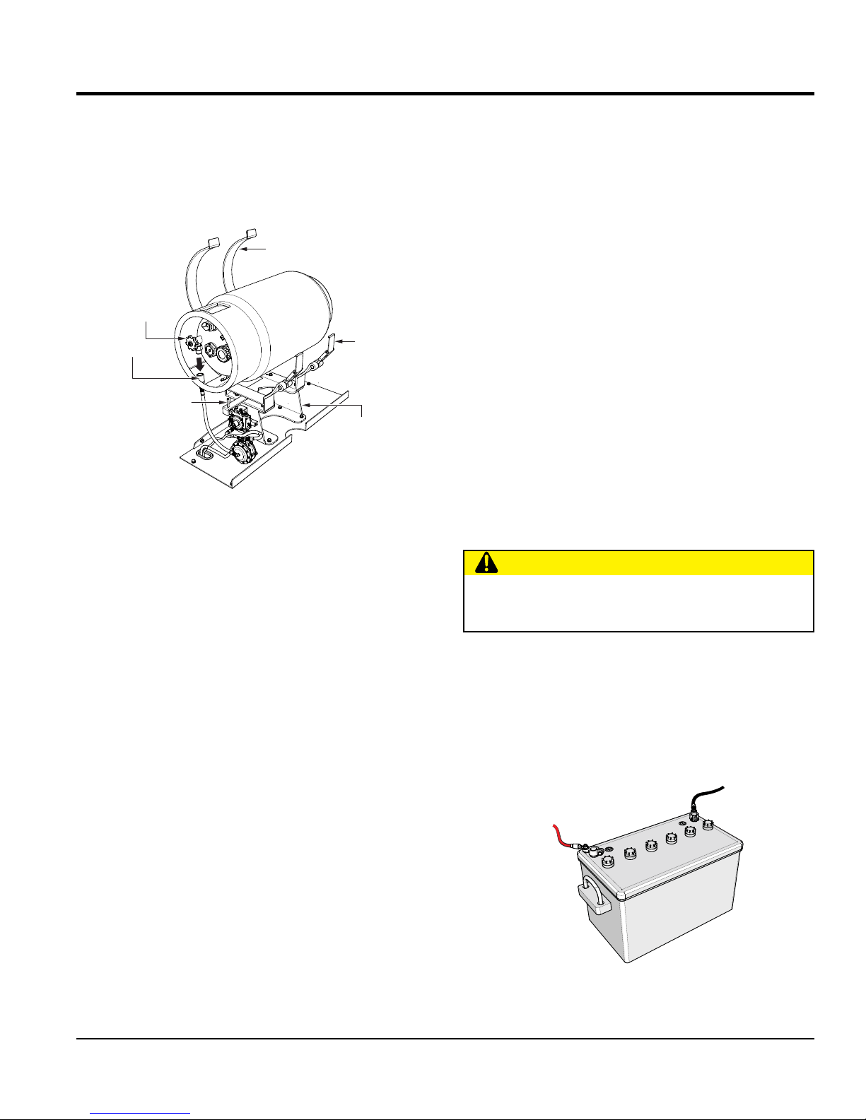
Procedure For Removing Propane Vapor Tank
1. Place machine on secure level ground where it will
not slip or slide.
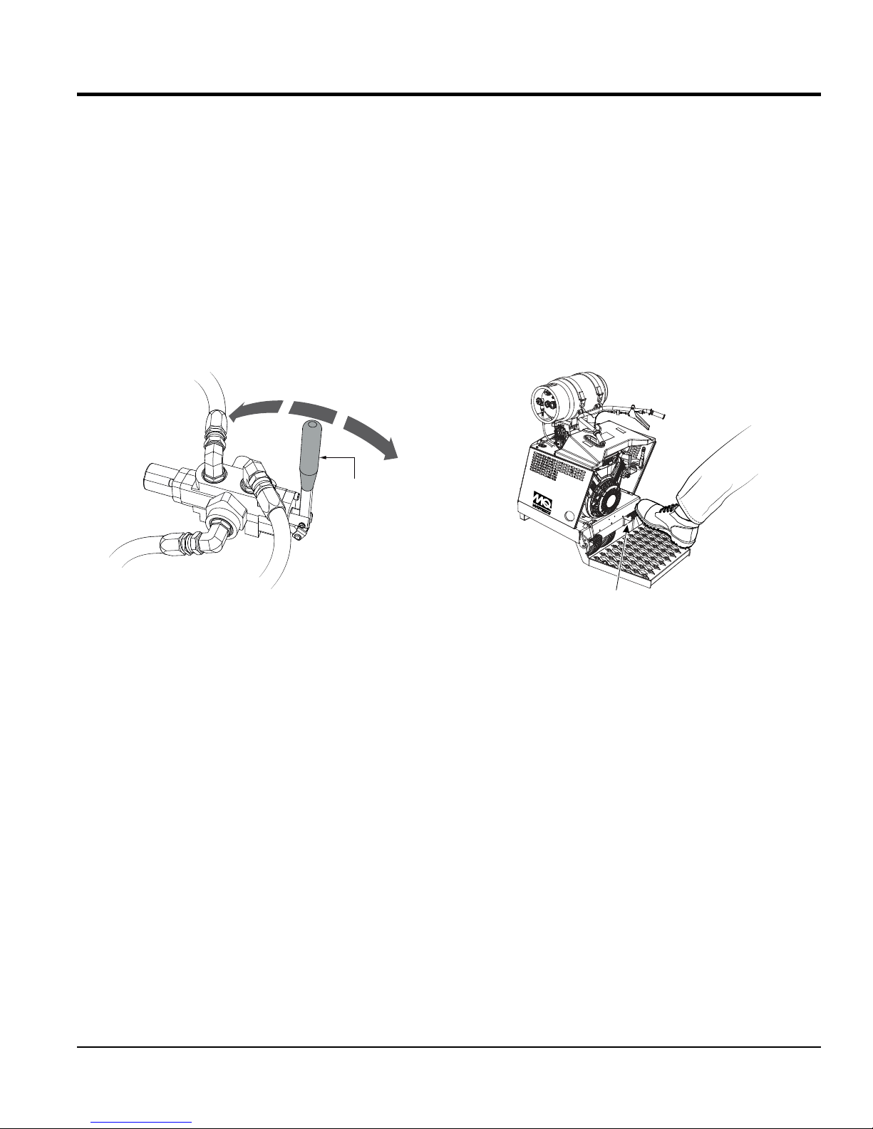
2. CLOSE shutoff valve (Figure 8) on propane tank.
LIFT/PULL
BACK STRAP
SHUT-OFF
VALVE
GAS LINE NOZZLE
LOCKING PIN
Figure 8. Propane Tank Removal
3. Unscrew the left-hand thread LPG gas line nozzle
from propane tank fill port.
LATCH
SUPPORT BRACKET
BATTERY
This unit is of negative ground DO NOT connect in reverse.
ALWAYS maintain battery fluid level between the specified
marks. Battery life will be shortened, if the fluid level are
not properly maintained. Add only distilled water when
replenishment is necessary.
DO NOT over fill. Check to see whether the battery cables
are loose. Poor contact may result in poor starting or
malfunctions.
ALWAYS keep the terminals firmly tightened. Coating the
terminals with an approved battery terminal treatment
compound. Replace battery with only recommended type
battery. The battery type used in this power buggy is BCI
Group U1.
The battery is sufficiently charged if the specific gravity
of the battery fluid is 1.28 (at 68° F). If the specific gravity
should fall to 1.245 or lower, it indicates that the battery is
dead and needs to be recharged or replaced.
Before charging the battery with an external electric source,
be sure to disconnect the battery cables.
CAUTION
4. Secure LPG gas nozzle/hose to the propane connection
port below the propane tank.
5. Release propane tank strap latches.
6. To remove propane tank, push backward and lift
upward.
7. Align the propane tank locking slot with the locking pin
on the tank support cradle and place new propane tank
into the support cradle.
8. Secure propane tank using straps with locking latches.
9. Reconnect LPG gas line nozzle to propane tank fill port.
10. OPEN shutoff valve on propane tank.
ALWAYS disconnect the negative terminal FIRST and
reconnect negative terminal LAST.
Battery Cable Installation
ALWAYS be sure the battery cables () are properly
connected to the battery terminals as shown below. The red
cable is connected to the positive terminal of the battery,
and the black cable is connected to the negative terminal
of the battery,
NEGATIVE
POSITIVE
Figure 9. Battery Connections
WBH-21EFP POWER BUGGY • OPERATION AND PARTS MANUAL — REV. #0 (03/01/18) — PAGE 19
Page 20
INSPECTION
When connecting battery do the following:
1. NEVER connect the battery cables to the battery
terminals when the ignition is in the ON position (start).
2. Place a small amount of battery terminal treatment
compound around both battery terminals. This will
ensure a good connection and will help prevent
corrosion around the battery terminals.
NOTICE
If the battery cable is connected incorrectly, electrical
damage to the power buggy will occur. Pay close attention
to the polarity of the battery when connecting the battery.
CAUTION
Inadequate battery connections may cause poor
starting of the power buggy, and create other
malfunctions.
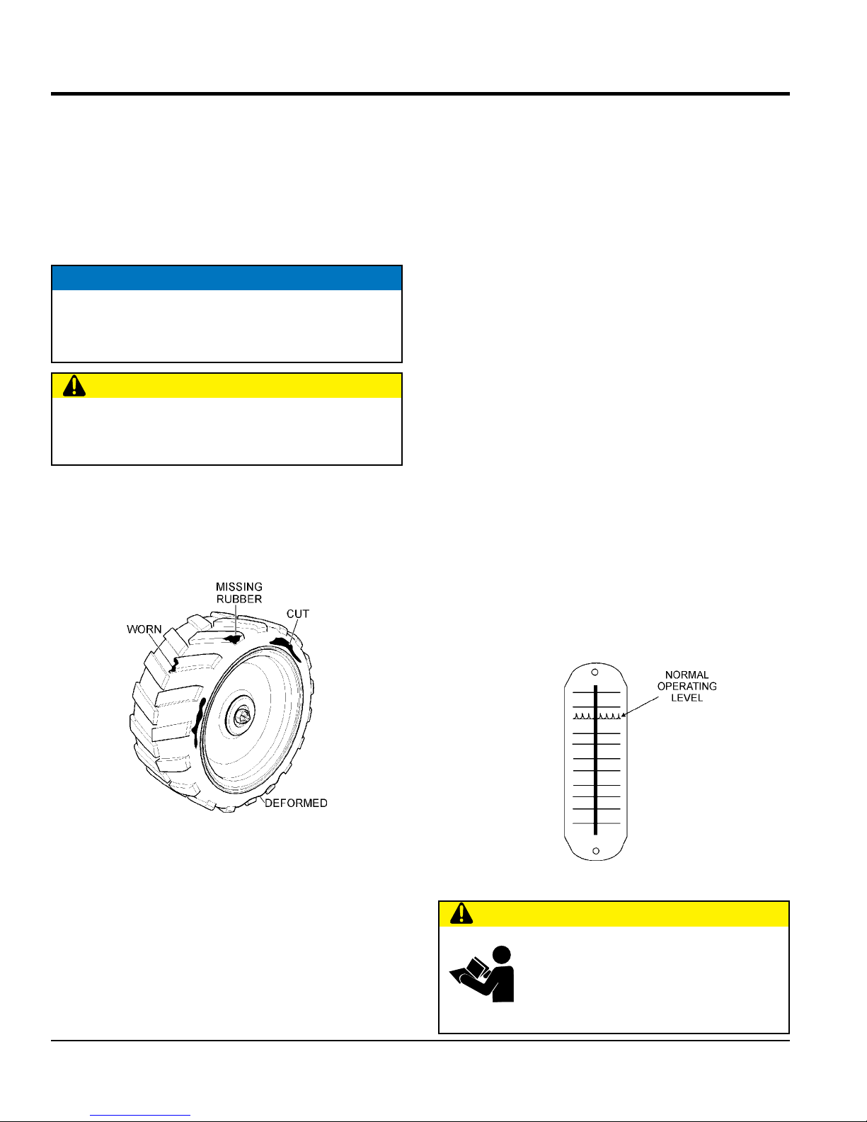
TIRE AND WHEEL WEAR CHECK
The tires (Figure 10) used on this power buggy are foam
filled and therefore do not have to be inflated. However
the tires shoud be inspected for cuts, wear and deformity.
PARKING BRAKE CHECK
Check the brakes as outlined in the maintenance section
of this manual.
LINKAGE CHECK
Check and make sure that all linkages within the buggy are
functioning correctly.
STEERING CHECK
1. Check and make sure that the power buggy's steering
turns freely and that there is no binding.
2. Make sure that the zerk fitting for the steering has
been lubricated.
DUMP CYLINDER CHECK
1. Check the power buggy's dump cylinder as outlined in
the operation section of this manual.
2. Make sure that both zerk fittings for the dump cylinder
have been lubricated.
HYDRAULIC OIL CHECK
3. Visually read the hydraulic sight glass (Figure 11) to
see if the hydraulic oil level is low.
Figure 10. Tire/Wheel Inspection
The wheels and tires of the power buggy are very important
for effective operation.
1. Check the tires regularly to make certain the lugs nuts
are tight.
2. Check wheels for cracks.
4. If the hydraulic oil is low, add enough hydraulic oil to
bring oil level to a normal safe operating level.
Figure 11. Hydraulic Sight Glass
CAUTION
DO NOT attempt to operate the power
buggy until the Safety Information, General
Information, and Inspection sections of this
manual have been read and thoroughly
understood.
PAGE 20 — WBH-21EFP POWER BUGGY • OPERATION AND PARTS MANUAL — REV. #0 (03/01/18)
Page 21
OPERATION
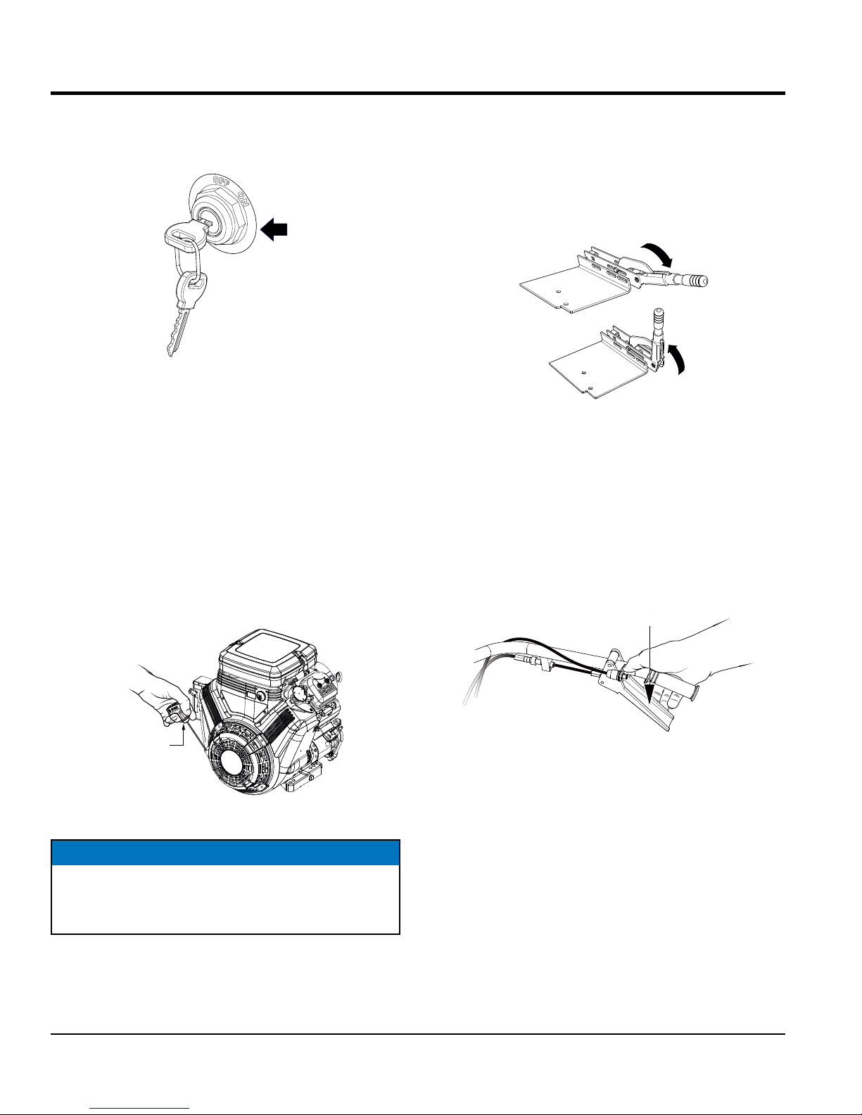
KILL SWITCH
ELECTRIC START (METHOD)
1. Before attempting to start the power buggy, make sure
that the safety kill switch (Figure 12) is not pushed
in. The power buggy will not start with the kill switch
engaged.
(PULL)
Figure 12. Kill Switch OFF
2. Place the travel control lever (Figure 13) in the
NEUTRAL position.
FORWARD
NEUTRAL
REVERSE
4. Move the throttle lever halfway between the FAST and
SLOW position (Figure 15) for starting.
FAST
SLOW
Figure 15. Throttle Lever (Midway Position)
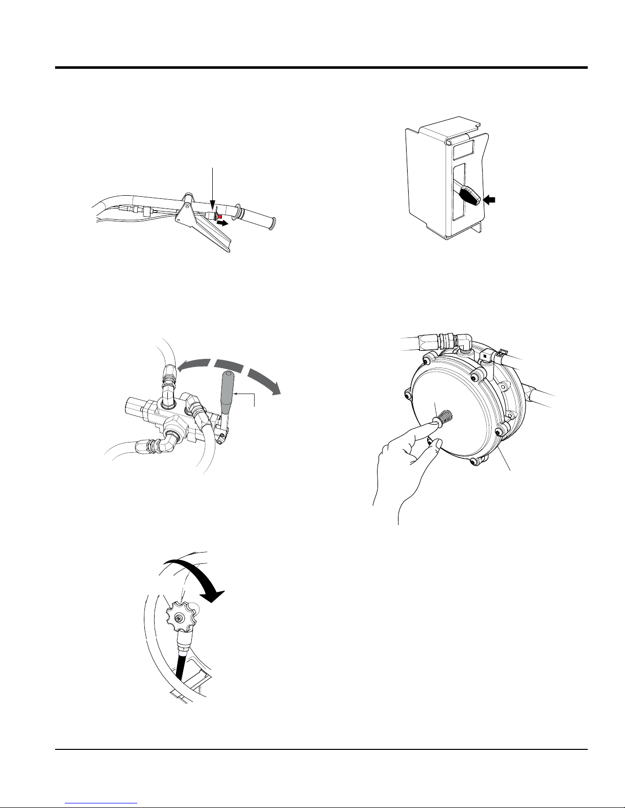
5. Press the primer button (Figure 16) on the vacuum
valve once. Pressing the button will allow pressure
to build up at the regulator (3.5~4.0 psi/ 24~ 27 kPa)
TRAVEL
CONTROL
LEVER
Figure 13. Travel Control Lever
3. Slowly OPEN the fuel shutoff valve (Figure 14) on the
propane tank.
SHUT-OFF
VALV E
OPEN
PRIMER
BUTTON
PRESS
VACUUM
VALV E
Figure 16. Primer Button
Figure 14. Fuel Shutoff Valve (OPEN)
WBH-21EFP POWER BUGGY • OPERATION AND PARTS MANUAL — REV. #0 (03/01/18) — PAGE 21
Page 22
OPERATION
6. Place the ignition key (Figure 17 ) in the START position
and hold it until the engine starts. When the engine
starts, release the key, allowing it to return back to the
ON position.
S
T
A
R
T
Figure 17. Engine Switch (Start Position)
7. Before the buggy is placed into operation, run the
engine for several minutes. Check for fuel leaks, and
noises that would associate with a loose guard or cover.
RECOIL START (METHOD)
1. Follow steps 1 through 5 of the Electric Start procedure.
2. Grasp the starter grip (Figure 18) and slowly pull it
out. The resistance becomes the hardest at a certain
position, corresponding to the compression point. Pull
the starter grip briskly and smoothly for starting.
PRE-CHECK
1. Engage the parking brake lever (Figure 19) and attempt
to rock the buggy back and forth. If the wheels turn
during the rocking motion, adjust the brakes as outlined
in the maintenance section of this manual.
PARKING BRAKE LEVER SET
PARKING BRAKE LEVER RELEASED
Figure 19. Parking Brake Lever
2. Place the engine's throttle lever (Figure 15) in the slow
(idle) position.
3. Check the speed control lever (Figure 20) located on
the right side of the handle bar. The speed control
should work freely when squeezed by hand, and return
to the neutral position when released.
SPEED CONTROL
LEVER
STARTER
GRIP
Figure 18. Starter Grip
NOTICE
DO NOT pull the starter rope all the way to the end.
DO NOT release the starter rope after pulling. Allow it
to rewind as soon as possible.
3. After the engine has started and warmed, slowly pull
the choke lever outward to the OPEN position.
4. If the engine has not started, repeat steps 1 through 3.
PAGE 22 — WBH-21EFP POWER BUGGY • OPERATION AND PARTS MANUAL — REV. #0 (03/01/18)
Figure 20. Speed Control Lever
Page 23
OPERATION
PARKING BRAKE/DIRECTION LEVER
Before the power buggy can be put into operational use,
it is best to perform a test run to make certain that all
components are functioning properly.
1. Place the buggy on flat solid ground.
2. Engage the parking brake lever.
3. Place the engine's throttle control (Figure 15) in the
SLOW (idle) position.
4. Place the power buggy's direction lever (Figure 21) in
the forward direction.
FORWARD
NEUTRAL
REVERSE
TRAVEL
CONTROL
LEVER
TRAVELING
1. With the engine running and parking brake released,
place the direction lever (Figure 21) in the forward
direction.
2. Squeeze the speed control lever (Figure 20) slightly
until the buggy begins to move in a forward direction.
Initially, let the buggy travel at about 3 MPH.
3. When using the buggy for the first time, test the brake.
With the right foot, step up and place it on the brake
pedal (Figure 22). Gradually apply pressure to the
brake pedal until the buggy comes to rest.
WBH21EFP
Figure 21. Direction Lever
5. Slowly squeeze the speed control lever slightly
(Figure 20), for a short period of time to test the brake
holding capacity. If the buggy moves forward, adjust
the brakes as outlined in the maintenance section of
this manual.
6. If the buggy does not move forward, release the
speed control, and disengage the parking brake. If
the buggy creeps forward or reverse while the parking
brake is disengaged, the machine will require service
adjustment of the pump control lever as outlined in the
maintenance section of this manual.
BRAKE PEDAL
Figure 22. Brake Pedal
4. Test the brake at different speeds until you are
comfortable with stopping the buggy. If the brakes
do not seem to stop the buggy adequately, refer to
the maintenance section of this manual for brake
adjustment instructions.
5. When starting and stopping is confirmed to be
functioning properly, the buggy is ready for operation.
WBH-21EFP POWER BUGGY • OPERATION AND PARTS MANUAL — REV. #0 (03/01/18) — PAGE 23
Page 24
OPERATION
TURN HANDLE BAR
CLOCKWISE TO STEER
BUGGY TO THE LEFT
TURN HANDLE BAR
COUNTERCLOCKWISE TO STEER
BUGGY TO THE LEFT
WBH21EFP
CORRECT
STEERING
To steer the buggy, use the handle bar in front of the
operator platform.
1. To turn left when traveling in the forward direction, turn
the handle bar clockwise (Figure 23).
100
95
90
85
80
75
70
65
60
55
50
45
PERCENT GRADE
40
35
30
25
20
15
10
5
0
100
95
90
85
80
75
70
65
60
55
50
45
PERCENT GRADE
40
35
30
25
20
15
10
5
0
10%
6°
10%
6°
35°
35°
45°
70%
45°
70%
100%
100%
0
10
5
0
10
5
35
30
DIRECTION OF TRAVEL
25
20
15
35
30
25
DIRECTION
20
OF TRAVEL
15
60
55
50
45
GRADE (DEGREES)
40
LEVEL BASE LINE
60
55
50
45
GRADE (DEGREES)
40
LEVEL BASE LINE
90
85
80
75
70
65
DISTANCE (D)
% GRADE = 100 (H¸ D)
90
85
80
75
70
65
DISTANCE (D)
% GRADE = 100 (H¸ D)
HEIGHT (H)
HEIGHT (H)
Figure 23. Steering the Buggy
2. To turn right when traveling in the forward direction,
turn the handle bar in the counterclockwise direction.
CAUTION
DO NOT steer the buggy left or right when traveling up
or down on a grade. Travel in a straight path.
CAUTION
Avoid sudden and quick turns. When steering, turn
the handle bar slowly. Always face the controls when
traveling.
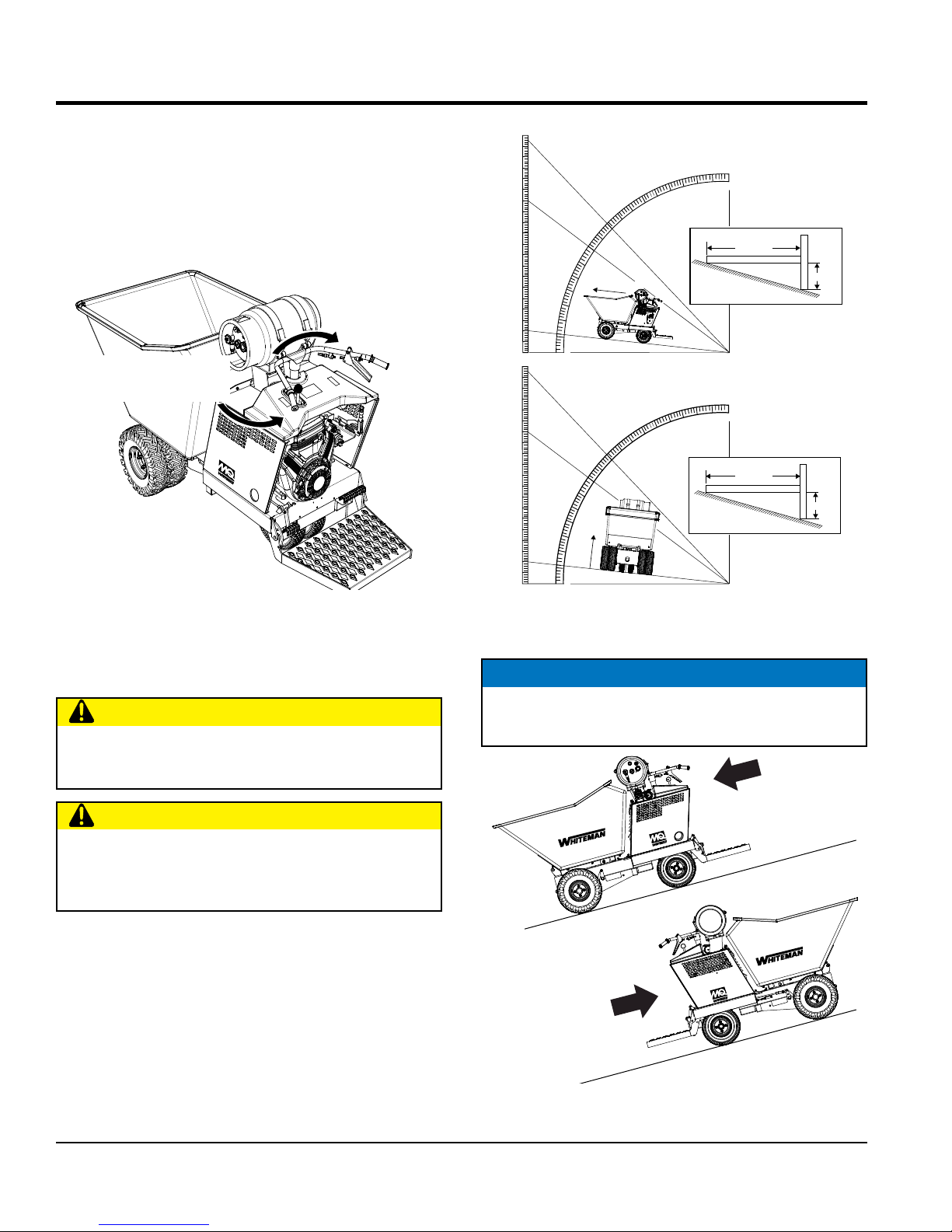
TRAVELING ON A SLOPE
1. When traveling on a slope, it is necessary to determine
the grade of the path. The buggy can travel up, down
or side to side on a maximum grade of 10% (6°). DO
NOT travel on steeper slopes.
To determine the % grade of your path of travel, use
the formula and graph in Figure 24.
Figure 24. Determining Grade of Slope
NOTICE
When going up or down a slope, always travel in the
forward direction (Figure 25).
DIRECTION
FOR TRAVELING
WBH-21EFP
WBH-21EFP
CORRECT
DIRECTION
FOR TRAVELING
UP A SLOPE
Figure 25. Slope Travel Direction
DOWN A SLOPE
PAGE 24 — WBH-21EFP POWER BUGGY • OPERATION AND PARTS MANUAL — REV. #0 (03/01/18)
Page 25
OPERATION
HORIZONTAL POSITION
TUB (BUCKET) DUMPING
NOTICE
DO NOT activate dump mechanism (tub/bucket) if
buggy is facing down hill. The possibility exist of the
buggy tipping over causing equipment damage and
severe bodily harm.
NOTICE
Releasing either one (dump control lever or pedal)
before dump is completed, will cause the tub to return
to the horizontal position.
The hydraulic dump can be controlled by the hand dump
control lever or foot dump pedal.
1. To place the tub in the vertical position press down on
the dump pedal (Figure 26A) or move the dump control
lever forward (Figure 26B). The tub will move to the
vertical position as long as pressure is continuously
applied to the dump pedal or the dump control lever is
held in the forward position.
2. To return the tub to the horizontal position, simply place
your foot underneath the dump pedal (Figure 26C) and
lift or pull back on the dump control lever (Figure 26D).
DUMP CONTROL LEVER
PUSH FORWARD TO DUMP
TUB (BUCKET)
DUMP PEDAL
PRESS DOWN
TO DUMP
DUMP PEDAL
LIFT UP TO
TO PLACE TUB IN
WBH21EFP
TUB (BUCKET)
WBH21EFP
DUMP
METHOD 1
A
TUB RETURN
METHOD 1
C
DUMP
METHOD 2
DUMP CONTROL LEVER
PULL BACKWARDS TO PLACE
TUB IN HORIZONTAL POSITION
TUB RETURN
METHOD 2
B
D
WBH-21EFP POWER BUGGY • OPERATION AND PARTS MANUAL — REV. #0 (03/01/18) — PAGE 25
Figure 26. Tub Dumping
Page 26

OPERATION
CLOSED
KILL SWITCH
SHUTDOWN (NORMAL)
Correct shutdown is important to safe operation. Follow
these general steps:
1. Come to a full stop.
2. Engage the parking brake (Figure 27).
PARKING BRAKE LEVER SET
Figure 27. Parking Brake Set
3. Place the throttle lever (Figure 28) in the slow position.
Idle engine 3-5 minutes for gradual cooling
5. Cycle hydraulic controls to eleminate residual pressure.
6. CLOSE the fuel shutoff valve (Figure 30). on the
propane tank.
SHUT-OFF
VA LV E
Figure 30. Fuel Shutoff Valve (CLOSED)
7. Remove ignition key.
8. Block wheels if on a slope or incline.
EMERGENCY SHUTDOWN
FAST
SLOW
Figure 28. Throttle Lever (Slow)
4. Place the ignition switch key (Figure 29 in the OFF
position
OFF
This power buggy is equipped with a safety kill switch. This
switch is located on the right side of the handle bar.
1. Push the power buggy's kill switch inward (Figure 31)
and listen for the engine to stop.
(PUSH)
Figure 31. Safety Kill Switch
2. Engage the parking brake (Figure 27).
3. Place the ignition switch key (Figure 29) in the OFF
position.
Figure 29. Ignition Switch (OFF)
PAGE 26 — WBH-21EFP POWER BUGGY • OPERATION AND PARTS MANUAL — REV. #0 (03/01/18)
Page 27

Table 5. Engine Maintenance Schedule
MAINTENANCE
EVERY 6
MONTHS
OR 100
HRS.
DESCRIPTION
(3)
OPERATION
BEFORE
EACH
USE
FIRST
MONTH OR
25 HRS.
EVERY
40 Hours
Check X
Engine Oil
Change X X
Engine Oil Filter Replace Every 100 Hrs.
Check X
Air Cleaner
Clean X (1)
Change X X (*)
Check/Adjust X
Spark Plugs
Replace X
Cooling Fins Clean X
Propane Tank
Components
Propane Hoses
Regulator
* - Replace the paper filter element only.
Check X
Check X
EVERY
YEAR
OR 300
HRS.
EVERY 2
YEARS OR
500 HRS.
(1) Service more frequently when used in DUSTY areas.
(2) These items should be serviced by your service dealer, unless you have the proper tools and are mechanically proficient. Refer to the
Briggs & Stratton, Vanguard Shop Manual for service procedures.
(3) For commercial use, log hours of operation to determine proper maintenance intervals.
Table 6. Power Buggy Maintenance Schedule
Periodic Maintenance Interval
Check Item OPERATION DAILY
Every
25 Hrs
Every
50 Hrs
Every
100-125
Hrs
Every 200
Hrs
Dump Cylinder Grease X
Steering Bearing Flange Grease X
Tub Bearing Pivot Block Grease X
Tub/Fastners Clean X X
Tub For Cracks/Deformations Check X
Tires For Severe Cuts/Wear Check X
Hydraulic Oil Level Check X X
Hydraulic Oil Replace X
Hydraulic Oil System Check X 1st time X
Brakes Check X
WBH-21EFP POWER BUGGY • OPERATION AND PARTS MANUAL — REV. #0 (03/01/18) — PAGE 27
Page 28

MAINTENANCE
When performing any maintenance on the power buggy
or engine, follow all safety messages and rules for safe
operation stated at the beginning of this manual.
WARNING
Accidental starts can cause severe injury or
death.
ALWAYS place the ON/OFF switch in the
OFF position.
Disconnect and ground spark plug leads
and disconnect negative battery cable
from battery before servicing.
WARNING
Some maintenance operations may
require the engine to be run. Ensure
that the maintenance area is well
ventilated. Exhaust contains poisonous
carbon monoxide gas that can cause
unconsciousness and may result in
DEATH
AIR CLEANER (100 HOURS)
Thoroughly remove dirt and oil from the engine and
control area. Clean or replace the air cleaner elements as
necessary. Check and retighten all fasteners as necessary.
1. Release the latch tabs (Figure 32) on each side of the
air cleaner cover, and remove cover.
NOTICE
Operating the engine with loose or damaged air cleaner
components could allow unfiltered air into the engine
causing premature wear and failure.
CAUTION
Wear protective equipment such as
approved safety glasses or face shields
and dust masks or respirators when
cleaning air filters with compressed air.
CAUTION
ALWAYS allow the engine to cool
before servicing. NEVER attempt any
maintenance work on a hot engine.
CAUTION
Operating the engine with a blocked screen (fan cover),
dirty or plugged cooling fins, and/or cooling shrouds
removed will cause engine damage due to overheating.
DANGER
DO NOT use gasoline as a cleaning solvent to avoid
creating the risk of fire or an explosion.
Figure 32. Air Filter Components
2. Remove knob and plate. Carefully remove air filter to
prevent dirt and debris from entering carburetor.
3. Remove outer foam filter.
4. Remove inner paper filter.
5. Inspect both air filter elements, replace them if
necessary.
PAGE 28 — WBH-21EFP POWER BUGGY • OPERATION AND PARTS MANUAL — REV. #0 (03/01/18)
Page 29

MAINTENANCE
6. To clean the paper air filter (Figure 33), tap the filter
element several times on a hard surface to remove
dirt, or blow compressed air [not to exceed 30 psi (207
kPa, 2.1 kgf/cm2)] through the filter element from the
air cleaner case side.
Figure 33. Cleaning Inner Paper Filter
7. NEVER! try to brush off dirt; brushing will force dirt
into the fibers. If the paper element is excessively dirty,
replace element.
8. Clean the foam air filter (Figure 34) element in warm
soapy water, rinse and allow to dry thoroughly or clean
with a nonflammable solvent and allow to dry. DO NOT
pour any type of oil into the foam element.
CHANGING ENGINE OIL (100 HOURS)
1. Drain the engine oil when the oil is warm as shown in
(Figure 35).
2. Remove the oil drain bolt and sealing washer and allow
the oil to drain into a suitable container.
Figure 35. Draining Engine Oil
3. Reinstall drain bolt with sealing washer and tighten
securely.
4. Replace engine oil with recommended type oil as
listed in Table 4. For engine oil capacity, see Table 2.
DO NOT over fill.
OIL FILTER (200 HOURS)
Figure 34. Cleaning Foam Element
9. Wipe dirt from the inside of the air cleaner body and
cover, using a moist cloth. Be careful not to let any
dirt or debris enter the air chamber that leads to the
carburetor.
10. Reinstall the foam air filter element to the air cleaner
cover, then reinstall the paper air filter element and
cover to the air cleaner case. Securely latch the hook
tabs onto the air cleaner cover.
1. Replace the engine oil filter (Figure 36) every 200 hours.
Figure 36. Oil Filter
2. Be sure to coat the seal of the new oil filter with clean
engine oil.
WBH-21EFP POWER BUGGY • OPERATION AND PARTS MANUAL — REV. #0 (03/01/18) — PAGE 29
Page 30

MAINTENANCE
SOLUTION
PROPANE TANK AND COMPONENTS
Inspection (Daily)
CAUTION
NEVER use bare hands when checking for leaks.
Escaping propane vapor and liquid freezes skin on
contact.
1. Visually inspect the propane tank (Figure 37), hose and
fitting and be alert to any foul odors.
DEFORMITY
EGG SMELL
CRACKS
LEAK
PROPANE TANK LEAK DETECTION
1. Apply an approved leak detector (Figure 38) solution,
obtained from a trained and qualified propane distributer,
or a thick non-ammonia soapy water solution (1:1 mixture
of 1 part non-ammonia soap and 1 part of water).
AIR
BUBBLES
LEAK DETECTOR
Figure 38. Leak Detection
LEAK
Figure 37. Propane Tank Inspection
2. Propane has a rotten egg smell added to it to help detect
a gas leak.
3. DO NOT use the propane system if the hoses are
deformed, damaged, kinked or flattened.
4. Ensure the propane tank is free of dents or damage. If
the tank shows signs of damage, replace it immediately.
5. Check the valve fitting openings for dirt or debris.
6. Check straps for cracks or deformity
7. Slowly open the shutoff valve all the way and listen for a
continuous hiss from the regulator, which may indicate
a leak.
8. Ensure that the tank is securely mounted to the equipment.
If the tank is loose, the hose or fittings may leak.
2. Using a small brush or spray bottle, apply the solution
around all fittings on the propane tank, regulator and
connections.
3. Slowly open the gas valve a half-turn.
4. If you detect bubbles, the joint or fitting has a leak. Shut off
the valve, tighten the leaking connection and slowly open
the valve again to half-turn. If leak persists, replace fitting
Fuel Lines
Check fuel lines and connections regularly for leaks or
damage. Repair or replace as necessary.
Replace fuel lines every two years to maintain the line's
performance and flexibility.
PAGE 30 — WBH-21EFP POWER BUGGY • OPERATION AND PARTS MANUAL — REV. #0 (03/01/18)
Page 31

MAINTENANCE
TROUBLE SHOOTING PROPANE FUEL SYSTEMS
DANGER
Use extreme caution when handling propane. Propane
is flammable and explosive and can cause personal
injury if not handled properly.
Use the following steps when the engine is not igniting or
irregular idling:
Propane Vapor Cylinder
Check the propane vapor cylinder service valve to see if
it is open. Open if closed and restart the engine.
Check the propane cylinder fuel gauge. Refill if empty.
High and Low Pressure Hoses
Check both ends of the high pressure fuel line between
the propane cylinder and regulator solenoid shut-off
valve. Make sure both ends are threaded tight on the
brass fittings.
SPARK PLUG ADJUSTMENT
1. Make sure the engine is cool before servicing the
spark plugs.
2. Disconnect the spark plug caps. Check for dirt and
remove any dirt from around the spark plug area.
3. Remove the spark plugs with a 5/8-inch spark plug
wrench.
4. If the spark plugs are damaged, the sealing washer is
in poor condition, or if the electrode is worn, replace
the spark plugs.
5. Measure the spark plug electrode gap (Figure 39) with
a wire-type feeler gauge. If needed, adjust the gap to
0.7 - 0.8 mm (0.028 - 0.031 in), by carefully bending
the side electrode.
Do the same with the low pressure hose to make sure
that both hose clamps on the end of the hose are tight.
Regulator
Open the Schrader valve cap and install a pressure
gauge with a range of 0-15 psi.
Turn the key to the on position without turning the
engine over and check the pressure at the regulator’s
Schrader valve. The pressure should be between
3.5~4.0 psi (24~ 27 kPa) adjust regulator if not within
the pressure range.
NOTICE
If there is pressure at the regulator the engine is getting
fuel. If no pressure is present check the trouble-shooting
points above.
Once complete and still no pressure, proceed with setting
the fuel flow on the regulator.
If you still show no pressure on the psi gauge, turn the
idler screw clockwise to increase fuel flow.
If pressure is still not present at the gauge after turning
the adjustment screw to the complete open position, then
the regulator is not working and will need to be replaced.
If the engine will not start and fuel is getting thru the
regulator, most likely the problem is not fuel related.
Figure 39. Spark Plug Gap
6. Install the spark plug carefully, by hand, to avoid cross
threading.
7. After the spark plug is seated, tighten with a 5/8-inch
spark plug wrench to compress the sealing washer.
8. When installing a new spark plug, tighten 1/2 turn, after
the spark plug seats, to compress the washer.
9. When reinstalling the original spark plug, tighten 1/8
to 1/4 turn after the spark plug seats to compress the
washer.
10. Reattach the spark plug caps.
ENGINE TUNE-UP ENGINE
See your engine manual for specific information on tuning up
your engine, checking and gaping the spark plugs, etc.
NOTICE
See the engine manual supplied with your machine
for appropriate engine maintenance schedule and
troubleshooting guide for problems.
WBH-21EFP POWER BUGGY • OPERATION AND PARTS MANUAL — REV. #0 (03/01/18) — PAGE 31
Page 32

LATCH
MAINTENANCE
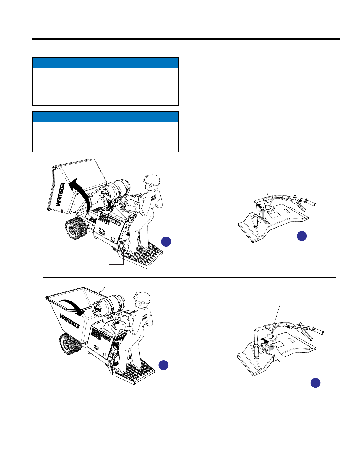
ADDING HYDRAULIC OIL
1. Check the hydraulic oil level in the hydraulic oil tank,
by reading the hydraulic oil sight glass (Figure 40)
mounted on the hydraulic oil tank.
Figure 40. Hydraulic Oil Sight Glass
2. If the hydraulic oil level is low, fill to the proper level with
EXXON/MOBIL NUTO H 46 or equivalent.
3. To gain access to the hydraulic oil tank filler hole, the
tub (Figure 41) must be placed in the dump position
(vertical).
5. Use the tub support rod to support the tub, then turn
the engine OFF.
6. Remove the two bolts that secure the access
cover(Figure 42) to the buggy frame.
ACCESS
COVER
REMOVE BOLT (2X)
Figure 42. Access Cover
4. Start the engine as outlined in the starting procedure,
then place the tub in the dumping position.
TUB (BUCKET)
DUMP CONTROL
LEVER
SUPPORT
ROD
WBH21EFP
DUMP PEDAL
Figure 41. Tub Dump Position
Hydraulic Oil Access
7. Lift up on access door and secure latch (Figure 43).
Figure 43. Securing Access Cover Latch
8. Remove the hydraulic oil filler cap (Figure 44), and add
hydraulic oil as required. Fill to the normal operating
mark as indicated on the hydraulic oil sight gauge.
PAGE 32 — WBH-21EFP POWER BUGGY • OPERATION AND PARTS MANUAL — REV. #0 (03/01/18)
Page 33

HYDRAULIC
OIL
HYDRAULIC
OIL TANK
HYDRAULIC
OIL ONLY
MAINTENANCE
The hydraulic drive motors (Figure 46) are extremely
reliable and will not need maintenance or repair under
normal conditions.
Figure 46. Hydraulic Drive Motor
Figure 44. Adding Hydraulic Oil
NOTICE
In climates where temperatures are below 35°F (1.6°C),
hard starting may occur. In these cases, the hydraulic oil
should be switched to a thinner 15 weight hydraulic fluid.
9. Replace hydraulic oil after every 200 hours of operation.
The reservoir capacity is 5.3 gallons (20.4 liters). The
hydraulic oil filter should be changed each time the
hydraulic oil is changed.
HYDRAULIC OIL FILTER REPLACEMENT
1. Replace the hydraulic oil filter (Figure 45) every 200
hours. Replace with only recommended type filter.
NOTICE
Contact Multiquip's Service Department should any
problems develop with the hydraulic drive motors
BRAKE ADJUSTMENT
Brake adjustment can be made on the brake linkage rod
located on the right-side of the buggy.
1. Place the parking brake lever in the engaged position.
The parking brake should be adjusted so that the buggy
will not move.
2. Adjustment is provided by a knob (Figure 47) at the
end of the parking brake lever. To tighten, turn the
knob clockwise.
PARKING
BRAKE
LEVER
CW
HYDRAULIC
OIL FILTER
Figure 45. Hydraulic Oil Filter
Hydraulic Drive Motors
WBH-21EFP POWER BUGGY • OPERATION AND PARTS MANUAL — REV. #0 (03/01/18) — PAGE 33
KNOB
Figure 47. Parking Brake Adjustment
Page 34

MAINTENANCE
3. Adjust the knob sufficiently tight so that when the
parking brake lever is pulled upward to the engaged
position (set), there is a sufficient amount of tension.
4. With the parking brake engaged, the buggy should not
move when the engine is started and the travel lever
placed in the forward position.
CHASSIS LUBRICATION
This power buggy is equipped with five zerk fittings
(Figure 48). Lubricate these zerk fittings each day before
operating the buggy.
1. Lubricate with high grade chassis lubricant at all
lubricating points listed below:
• Dump Cylinder Pivots - Two zerk fittings
• Tub Bearing Pivot Blocks (Underside of Tub) - Two
zerk fittings.
• Steering Bearing Flange (Front Side of Handle Bar) One zerk fitting.
PUMP CONTROL LEVER ADJUSTMENT
Inspect the speed control return springs. The tension should
be sufficient to allow lever to snap back when released.
Replace any broken, deformed, or damaged springs.
If the power buggy tends to creep in the forward or reverse
directions after you release the speed control lever, the
pump control lever requires adjustment.
1. Place the machines drive wheels on jacks or blocks
free from ground contact.
2. Locate the pump control lever adjustment bolt
(Figure 49).
Figure 48. Lubrication Points
2. Remove rear wheel hubs and repack bearings after
every 400 hours of operation.
PAGE 34 — WBH-21EFP POWER BUGGY • OPERATION AND PARTS MANUAL — REV. #0 (03/01/18)
Figure 49. Pump Control Lever Adjustment
3. Loosen the jam nut.
4. Start the engine and place the buggy's directional
control lever in the forward then reverse directions
while observing for wheel movement.
5. The pump lever has a very sensitive neutral position of
about 1/32" to 1/16". If the wheels are creeping, turn
the adjusting bolt in very slight increments.
6. Tap lever up or down to determine neutral position.
Tighten both nuts when correct neutral position has
been achieved.
7. If wheels are creeping in reverse, turn the adjusting
bolt counterclockwise. If wheels are creeping forward,
turn the adjusting bolt clockwise.
Page 35

MAINTENANCE
TIRES/WHEELS/LUG NUTS
Tires and wheels are very important and critical components
of the buggy. When specifying or replacing the wheels, it
is important that the wheels, tires, and axle are properly
matched.
CAUTION
DO NOT attempt to repair or modify a wheel. If the rim
is cracked, replace the rim immediately and inspect the
tire for cuts, wear, and deformations.
TIRE WEAR
The tires (Figure 50) used on this power buggy are foam
filled and therefore do not have to be inflated. However
the tires shoud be inspected for cuts, wear and deformity.
Table 7. Tire Torque Requirements
Wheel Size
480 x 8 in. 20-25 35-40 50-65
3. After first road use, retorque all lug nuts in sequence
Check all wheel lug nuts periodically.
First Pass
FT-LBS
Second Pass
FT-LBS
Third Pass
FT-LBS
Figure 50. Tire Inspection
LUG NUT TORQUE REQUIREMENTS
It is extremely important to apply and maintain proper wheel
mounting torque on the trailer. Be sure to use only the
fasteners matched to the cone angle of the wheel. Proper
procedure for attachment of the wheels is as follows:
1. Start all wheel lug nuts by hand.
2. Torque all lug nuts (Figure 51) in sequence. DO NOT
torque the wheel lug nuts all the way down. Tighten
each lug nut in 3 separate passes as defined by Table 7.
Figure 51. Lug Nut Torque Sequence
LONG TERM STORAGE
Drain the fuel tank completely, or add STA-BIL to the fuel.
Remove spark plug and pour a few drops of motor oil into
cylinder. Crank engine 3 to 4 times so that oil reaches
all internal parts.
Clean exterior with a cloth soaked in clean oil.
Remove the battery.
Store unit covered with plastic sheet in moisture and
dust-free location out of direct sunlight.
CAUTION
NEVER store the power buggy with fuel in the tank for
any extended period of time. ALWAYS clean up spilled
fuel immediately.
WBH-21EFP POWER BUGGY • OPERATION AND PARTS MANUAL — REV. #0 (03/01/18) — PAGE 35
Page 36

TROUBLESHOOTING
Troubleshooting (Power Buggy)
Symptom Possible Problem Solution
Speed control cable out of adjustment?
Loss of Power.
Loss of Travel.
System Operating Hot.
Slow Dumping.
System jerky when started.
Diffi cult to steer. Un-lubricated steering column? Lubricate steering column.
Parking brake will not hold. Brake linkage out of adjustment? Adjust.
Diffi culty in stopping
Engine will not start.
.
Hydraulic oil level low.? Check hydraulic oil level. Add oil if necessary.
Contaminated hydraulic oil fi lter? Replace hydraulic oil fi lter. Clean system.
Low engine RPM? Check engine speed.
Forward/Reverse lever in neutral position?
Parking brake partially engaged? Release parking brake.
Hydraulic oil level low?
Defective cooling fan? Inspect cooling fan, replace if necessary.
Low engine speed?
Dump cylinder is internally bypassing oil? Replace dump cylinder or seal.
Dump valve pressure low?
Speed cable out of adjustment? Adjust speed control cable.
Defective drive motors? Check drive motors, replace if necessary.
Brakes out of adjustment? Brake lining worn. Replace brake lining.
Low on fuel or propane tank empty? Add fuel.
Defective kill switch? Check kill switch. Replace if necessary
Engine ON/OFF switch in OFF position? Set engine ON/OFF switch to ON position.
Propane Shut-off valve CLOSED? Open shut-off valve.
Defective propane fuel regulator? Check or replace fuel regulator
Worn High/Low Pressure Hoses?
Adjust speed control cable. Replace cable if
necessary
Place lever in either forward or reverse position.
Check hydraulic motors.
Check hydraulic oil level add hydraulic oil if
necessary.
Check engine speed. Adjust engine speed if
necessary.
Check dump valve relief pressure. Pressure
should be 1000 psi ± 50 psi.
Check or replace hoses
PAGE 36 — WBH-21EFP POWER BUGGY • OPERATION AND PARTS MANUAL — REV. #0 (03/01/18)
Page 37

Symptom Possible Problem Solution
Diffi cult to start, fuel is available, but no spark at
spark plug.
Diffi cult to start, fuel is available, and spark is
present at the spark plug.
Diffi cult to start, fuel is available, spark is
present and compression is normal.
Diffi cult to start, fuel is available, spark is
present and compression is low.
No fuel present at carburetor.
TROUBLESHOOTING
Troubleshooting (Engine)
Spark plug bridging? Check gap, insulation or replace spark plug.
Carbon deposit on spark plug? Clean or replace spark plug.
Short circuit due to defi cient spark plug
insulation?
Improper spark plug gap? Set to proper gap.
Spark plug is red? Check transistor ignition unit.
Spark plug is bluish white?
No spark present at tip of spark plug?
No oil? Add oil as required.
Oil pressure alarm lamp blinks upon starting? (if
applicable)
ON/OFF switch is shorted? Check switch wiring, replace switch.
Ignition coil defective? Replace ignition coil.
Improper spark gap, points dirty? Set correct spark gap and clean points.
Condenser insulation worn or short circuiting? Replace condenser.
Spark plug wire broken or short circuiting? Replace defective spark plug wiring.
Defective fuel pressure regulator?
Air cleaner dirty? Clean or replace air cleaner.
Suction/exhaust valve stuck or protruded? Reseat valves.
Piston ring and/or cylinder worn? Replace piston rings and/or piston.
Cylinder head and/or spark plug not tightened
properly?
Head gasket and/or spark plug gasket damaged? Replace head and spark plug gaskets.
Propane tank empty? Fill with correct type of LPGl.
Shutoff valve closed? Open shutoff valve
Defective propane regulator? Check or replace regulator.
Defective propane fuel hoses? check or replace hoses.
Check spark plug insulation, replace if worn.
If insuffi cient compression, repair or replace
engine. If injected air leaking, correct leak. If
carburetor jets clogged, clean carburetor.
Check transistor ignition unit is broken, and
replace defective unit. Check if voltage cord
cracked or broken and replace. Check if spark
plug if fouled and replace.
Check automatic shutdown circuit, "oil sensor".
(if applicable)
Check or replace regulator.
Contact MQ Service Dept.
Torque cylinder head bolts and spark plug.
WBH-21EFP POWER BUGGY • OPERATION AND PARTS MANUAL — REV. #0 (03/01/18) — PAGE 37
Page 38

Symptom Possible Problem Solution
Weak in power, compression is proper and
does not misfi re.
Weak in power, compression is proper but
misfi re.
Engine overheats
Rotational speed fl uctuates.
Recoil starter malfunctions. (if applicable)
Starter malfunctions.
Burns too much fuel.
Exhaust color is continuously "white".
Exhaust color is continuously "black".
Will not start, no power with key "ON". (if
applicable)
TROUBLESHOOTING
Troubleshooting (Engine) - continued
Air cleaner dirty? Clean or replace air cleaner.
Improper level in carburetor? Check fl oat adjustment, rebuild carburetor.
Defective spark plug? Clean or replace spark plug.
Improper spark plug? Set to proper gap.
Dirty spark plug? Clean or replace spark plug.
Ignition coil defective? Replace ignition coil.
Wrong type of fuel? Replace with correct type of fuel.
Cooling fi ns dirty? Clean cooling fi ns.
Intake air restricted?
Oil level too low or too high? Adjust oil to proper level.
Governor adjusted incorrectly? Adjust governor.
Governor spring defective? Replace governor spring.
Fuel fl ow restricted? Check entire fuel system.
Recoil mechanism clogged with dust and dirt? Clean recoil assembly with soap and water.
Spiral spring loose? Replace spiral spring.
Loose, damaged wiring?
Battery insuffi ciently charged? Recharge or replace battery.
Starter damaged or internally shorted? Replace starter.
Over-accumulation of exhaust products?
Wrong spark plug?
Lubricating oil is wrong viscosity? Replace lubricating oil with correct viscosity.
Worn rings? Replace rings.
Air cleaner clogged? Clean or replace air cleaner.
Poor carburetor adjustment, engine runs too
rich?
ON/OFF device not activated ON? Turn on ON/OFF device.
Battery disconnected or discharged?
Ignition switch/wiring defective? Replace ignition switch. Check wiring.
Clear intake of dirt and debris. Replace air
cleaner elements as necessary.
Ensure tight, clean connections on battery
and starter.
Check and clean valves. Check muffl er and
replace if necessary.
Replace spark plug with manufacturer's
suggested type.
Adjust fuel pressure regulator.
Check cable connections. Charge or replace
battery
PAGE 38 — WBH-21EFP POWER BUGGY • OPERATION AND PARTS MANUAL — REV. #0 (03/01/18)
Page 39

HYD. OIL FILTER
200 MICRON
SCREEN/MESH
CHARGE
PUMP
HYDRAULIC SYSTEM DIAGRAM
HYDRAULIC
OIL TANK
DUMP CYLINDER
RELIEF
VALVE
1000 PS1
± 50
A
A B
EATON
PUMP
17 GPM
DIRECTION VALVE DUMP VALVE
OUT
IN
SPIN-ON
RETURN FILTER
10 MICRON
A
IN
B
OUT
DRIVE MOTOR
NORMALLY UP TO
17 GPM
WBH-21EFP POWER BUGGY • OPERATION AND PARTS MANUAL — REV. #0 (03/01/18) — PAGE 39
DRIVE MOTOR
NORMALLY UP TO
17 GPM
Page 40

FRAME
HYDRAULIC
OIL TANK
DRIVE
MOTORS
HYDRAULIC
PUMP
HYDRAULIC
OIL FILTER
DUMP
VALVE
DUMP
CYLINDER
HYDRAULIC HOSE CONNECTIONS
PAGE 40 — WBH-21EFP POWER BUGGY • OPERATION AND PARTS MANUAL — REV. #0 (03/01/18)
Page 41

CHARGE COIL
CHASSIS
GND.
M
CHASSIS
GND.
BATTERY
POSITIVE
NEGATIVE
CHASSIS
GND.
STARTER
MOTOR
OIL LEVEL
SWITCH
UNIT
IGNITION
COIL
SPARK
PLUG
(RIGHT)
CHASSIS
GND.
121
2
S
B
M
G
IGNITION
SWITCH
OIL LEVEL
NORMAL
LOW LEVEL
SWITCH
POSITION
OPEN
CLOSED
RUN
OFF
ENGINE
OIL LEVEL SWITCH
OFF
RUN
START
G+M+A
IGNITION SWITCH
POSITION
CIRCUIT MAKE
B+L+A
B+L+S
YEL
12 AWG
EMERGENCY
STOP SWITCH
IGNITION
SWITCH
CONNECTOR
A
L
UNIT
IGNITION
COIL
SPARK
PLUG
(RIGHT)
CHASSIS
GND.
VOLTAGE
REGULATOR
RECTIFER
RED
12 AWG
RED
12 AWG
SOLENOID
STARTER
+12 VDC OUT
CAP
SPLICE
SPLICE
GRN
12 AWG
BLK
12 AWG
BLK
12 AWG
BLK
12 AWG
FUEL CUT-OFF
SOLENOID
CHASSIS
GND.
YEL
12 AWG
ORG
12 AWG
RED
RED
ORG
12 AWG
BRN
12 AWG
WHT
12 AWG
JUMPER
CABLE
YEL
12 AWG
ENGINE WIRING DIAGRAM
WBH-21EFP POWER BUGGY • OPERATION AND PARTS MANUAL — REV. #0 (03/01/18) — PAGE 41
Page 42

EXPLANATION OF CODE IN REMARKS COLUMN
The following section explains the different symbols and
remarks used in the Parts section of this manual. Use the
help numbers found on the back page of the manual if there
are any questions.
SAMPLE PARTS LIST
NO.
1 12345 BOLT
2% WASHER, 1/4 IN.
2% 12347 WASHER, 3/8 IN.
3 12348 HOSE
4 12349 BEARING
NO. Column
PART NO. Column
QTY. Column
— Item quantity can be indicated by a
A/R (As Required) is generally used for hoses or other
A blank entry generally indicates that the item is not sold
separately. Other entries will be clarifi ed in the “Remarks”
Some of the most common notes found in the “Remarks”
Column are listed below. Other additional notes needed
— All items on the parts list with the
same unique symbol will be included when this item is
— Used to list an effective serial
— Indicates that the part
is used only with the specifi c model number or model
number variant listed. It can also be used to show a
part is NOT used on a specifi c model or model number
— Indicates that the part can
be purchased at any hardware shop or made out of
available items. Examples include battery cables, shims,
— Indicates that an item cannot
be purchased as a separate item and is either part of an
assembly/kit that can be purchased, or is not available
Numbers Used
number, a blank entry, or A/R.
NOTICE
The contents and part numbers listed in the parts
section are subject to change without notice. Multiquip
does not guarantee the availability of the parts listed.
PART NO. PART NAME QTY. REMARKS
.....................1 .....INCLUDES ITEMS W/%
..........NOT SOLD SEPARATELY
..1 .....MQ-45T ONLY
..................A/R ...MAKE LOCALLY
..............1 .....S/N 2345B AND ABOVE
Unique Symbols — All items with same unique symbol
(@, #, +, %, or >) in the number column belong to the
same assembly or kit, which is indicated by a note in the
“Remarks” column.
Duplicate Item Numbers — Duplicate numbers indicate
multiple part numbers, which are in effect for the same
general item, such as different size saw blade guards in
use or a part that has been updated on newer versions
of the same machine.
parts that are sold in bulk and cut to length.
Column.
REMARKS Column
to describe the item can also be shown.
Assembly/Kit
purchased.
Indicated by:
“INCLUDES ITEMS W/(unique symbol)”
Serial Number Break
number range where a particular part is used.
Indicated by:
“S/N XXXXX AND BELOW”
“S/N XXXX AND ABOVE”
“S/N XXXX TO S/N XXX”
NOTICE
When ordering a part that has more than one item
number listed, check the remarks column for help in
determining the proper part to order.
Numbers Used — Part numbers can be indicated by a
number, a blank entry, or TBD.
TBD (To Be Determined) is generally used to show a
part that has not been assigned a formal part number
at the time of publication.
A blank entry generally indicates that the item is not sold
separately or is not sold by Multiquip. Other entries will
be clarifi ed in the “Remarks” Column.
Specifi c Model Number Use
variant.
Indicated by:
“XXXXX ONLY”
“NOT USED ON XXXX”
“Make/Obtain Locally”
and certain washers and nuts.
“Not Sold Separately”
for sale through Multiquip.
PAGE 42 — WBH-21EFP POWER BUGGY • OPERATION AND PARTS MANUAL — REV. #0 (03/01/18)
Page 43

SUGGESTED SPARE PARTS
WBH-21EF POWER BUGGY
1 to 3 units
Qty. P/N Description
1............508667 ..................FILTER, HYDRAULIC OIL
1............EM16477 .............. CAP, HYDRAULIC OIL TANK
1............18035 ....................PUMP, HYDROSTATIC
1............18051 ....................COUPLING, ENGINE SHAFT
2............512881 ..................BRAKE BAND ASSY.
1............18145 ....................ROD, BRAKE CONTROL
1............520820 ..................CAP, FUEL (EPA)
5............845125 ..................FILTER, IN-LINE FUEL
1............18131 ....................SWITCH, KILL
1............18133 ....................CABLE, THROTTLE
1............18132 ....................LEVER ,THROTTLE
1............18029F .................WHEEL, DRIVE, FOAM
1............18049F .................WHEEL, STEERING, FOAM
1............18016 ....................CABLE, PARKING BRAKE
NOTICE
Part numbers on this Suggested Spare Parts list may
supersede/replace the part numbers shown in the
following parts lists.
B&S VANGUARD 18 HP GASOLINE ENGINE
1 to 3 units
Qty. P/N Description
3............496018S ............... SPARK PLUG
3............691959 ..................KEY, IGNITION
3............808167 ..................GRIP, STARTER
1............66574 ....................ROPE, STARTER
3............394018S ............... AIR FILTER
3............272490S ............... PRE-CLEANER
3............842921 ..................OIL FILTER
WBH-21EFP POWER BUGGY • OPERATION AND PARTS MANUAL — REV. #0 (03/01/18) — PAGE 43
Page 44

9
LIFT
NAMEPLATE AND DECALS ASSY.
1
WARNING
CRUSH AREA
513608
18247
TRAVEL
SAFETY
INSTRUCTIONS
1. Read owner’s manual
before operating.
2. Keep unauthorized and untrained
people away from machine during
operation.
3. Make sure all safety devices are in
place before this machine is started.
4. Make sure engine is turned off and
spark plug wire is disconnected before
cleaning the machine.
5. Keep hands and ngers away from
moving objects.
6. Do not operate machine in an enclosed
area, proper ventilation is required.
7. Never leave machine unattended when
operating.
8. Always stop engine and allow engine
to cool before adding fuel or oil.
14
12
3
2
4
NEUTRAL
MODEL
SERIAIAL NO.
17
8
CIP520935
MQ Whiteman Safety Instructions
Operate at safe speeds only
Read operators manual before operating
Place in neutral before starting
No unauthorized untrained operators
11
BUCKET
Dump
No riders
Be sure all safety devices are operational and in
place before starting the engine
Disconnect spark plugs before service
Never operate in an enclosed area
Never leave unattended when operating
Allow engine to cool before adding uids
LIFTLIFT
LIFT
18245
WARNING
6
HOT SURFACE
AREA
5
18248
9
513608
LIFT
10
18
Return
8
18245
LIFTLIFT
LIFT
WARNING
To avoid injury
you MUST read
and understand
operator’s manual
before using this
machine.
This machine to
be operated by
qualied
personnel only.
Ask for training
as needed.
P/N35137
16
LIFT
8
PAGE 44 — WBH-21EFP POWER BUGGY • OPERATION AND PARTS MANUAL — REV. #0 (03/01/18)
8
18245
LIFTLIFT
LIFT
2
HYDRAULIC
OIL ONLY
13
985
6
QUALITY
18245
MANAGEMENT SYSTEM
CERTIFIED ON
ISO 9001:2008
518524
HYDRAULIC
OIL TANK
15
Page 45

NAMEPLATE AND DECALS ASSY.
NO. PART NO. PART NAME QTY. REMARKS
1 18247 DECAL, CRUSH WARNING 1
2 DECAL, TRAVEL LEVER DIRECTION .....................1..........MOLDED INTO FUEL TANK COVER
3 PLATE, SERIAL NUMBER........................................1..........CONTACT MQ PARTS DEPT.
4 491757 RIVET, I.D. PLATE 2
5 18248 DECAL, HOT SURFACE WARNING 1
6 804592 DECAL, WBH-21 2
7 18252 DECAL, MQ WHITEMAN 2
8 18245 DECAL, FORKLIFT LIFTING 6
9 513608 DECAL, LIFTING HOOK 3
10 RPS150028 PLATE, PROPANE TANK, 33.5LBS 1
11 DECAL,
12 DECAL, BUCKET DUMP LEVER .............................1..........MOLDED INTO FUEL TANK COVER
13 EM985 DECAL, HYDRAULIC OIL 1
14 520935 DECAL,
15 518524 DECAL, ISO 9001:2008 1
16 35137 DECAL, READ MANUAL, ASK FOR TRAINING 1
17 RPS150029 DECAL, INSTRUCTION, PROPANE 1
18 RPS150030 DECAL, SAFETY, PROPANE 1
WHITEMAN SAFETY INSTRUCTIONS
SAFETY INSTRUCTIONS
1
..........1..........MOLDED INTO FUEL TANK COVER
WBH-21EFP POWER BUGGY • OPERATION AND PARTS MANUAL — REV. #0 (03/01/18) — PAGE 45
Page 46

VIEW FROM OPERATOR’S
PLATFORM
HYDRAULIC DRIVE ASSY.
2
HYDRAULIC
OIL ONLY
1
3
2
DIRECTIONAL
23
1
VALVE
16
19
17
RIGHT
DRIVE MOTOR
NOTES:
REFERENCE HYDRAULIC HOSE
1
CONNECTION SECTION.
REFERENCE PUMP ASSEMBLY.
2
21
20
6
18
DRIVE MOTOR
18
LEFT
17
19
15
22
22
14
16
13
12
8
6
SEAL KIT
DRIVE
MOTOR
25
5
24
10
9
7
PAGE 46 — WBH-21EFP POWER BUGGY • OPERATION AND PARTS MANUAL — REV. #0 (03/01/18)
11
8
Page 47

HYDRAULIC DRIVE ASSY.
NO. PART NO. PART NAME QTY. REMARKS
1 18265M HOSE, DIRECTION VALVE .................................1................RIGHT-DRIVE MOTOR
2 18264M HOSE, DIRECTION VALVE .................................1................LEFT-DRIVE MOTOR
3 511810 ADAPTER, ELBOW 2
5 18276M HOSE, LH HYDRAULIC MOTOR 1
6 512189 ADAPTER, TEE CONNECTOR 2
7 492527 NUT, HEX 1/2"-20 8
8 18029F WHEEL, DRIVE ASSY. FRONT .........................4................FOAM FILLED TIRE
9$ 511692 FLANGE, HUB 2
10$ 18237 LUG BOLT/HUB FLANGE 8
11 492584 NUT, HEX 1/2"-13 NYLON .................................8................REPLACES P/N 6109160
12 18190 SCREW, HUB STUD 1/2"-20 X 2-3/4" 8
13 491689 KEY, COTTER 1/8" X 2 2
14 PT018038 NUT, CASTLE 1-1/8"-18 2
15 803281 HUB, DRIVE (INDEXED) 2
16 3365 ADAPTER, STRAIGHT 5
17 505718 SCREW, HHC 1/2"-13 X 2-3/4" 8
18 18011 MOTOR, HYDRAULIC DRIVE 2
19 3311 KEY, 7 MM X 8 MM X 1-1/4" ..............................2................REPLACES P/N PE449105
20 6109180 WASHER, LOCK 1/2" 8
21 6109160 NUT, HEX 1/2"-13 8
22 18027 HOSE, DRIVER MOTOR CROSSOVER 2
23 18275M HOSE, RH HYDRAULIC MOTOR 1
24 516528 FLANGE HUB ASSY. .........................................1................INCLUDES ITEMS W/$
25 18011SK SEAL KIT, DRIVE MOTOR 1
WBH-21EFP POWER BUGGY • OPERATION AND PARTS MANUAL — REV. #0 (03/01/18) — PAGE 47
Page 48

1
REFERENCE HYDRAULIC HOSE
CONNECTION SECTION.
NOTES:
1
1
2
REFERENCE HYDRAULIC OIL
TANK ASSEMBLY.
3
REFERENCE DUMP VALVE ASSEMBLY.
2
3
4
REFERENCE HYDRAULIC DRIVE
ASSEMBLY ITEMS 1 AND 2 FOR
HOSE PART NUMBERS
4
HYDRAULIC
OIL FILTER
DIRECTION
VALVE
13
13
3
5
6
2
1
14
13
8
8
11
12
12
3
DUMP VALVE
2
10
15
7
16
13
13
HYDRAULIC
PUMP
9
HYDRAULIC
OIL TANK
SEAL KIT
DIRECTIONAL
VALV E
18
17
14A
4
HYDRAULIC PUMP ASSY.
PAGE 48 — WBH-21EFP POWER BUGGY • OPERATION AND PARTS MANUAL — REV. #0 (03/01/18)
Page 49

HYDRAULIC PUMP ASSY.
NO. PART NO. PART NAME QTY. REMARKS
1 18035 PUMP, HYDRAULIC 1
2 511808 ADAPTER, STRAIGHT 2
3 3365 ADAPTER, STRAIGHT 6
4 18256M HOSE, PUMP TO DUMP VALVE 1
5 18258M HOSE, FILTER TO PUMP 1
6 18261M HOSE, PUMP TO TANK 1
7 18265M HOSE, PUMP TO DIRECTION VALVE ..............1................REPLACES P/N 18263M
8 512190 ADAPTER, STRAIGHT 2
9 18257M HOSE, FILTER TO DUMP VALVE 1
10 508667 FILTER, HYDRAULIC 1
11 508664 HYDRAULIC FILTER HEAD 1
12 511799 ADAPTER, ELBOW 2
13 3322 ADAPTER, ELBOW 6
14 18058 VALVE, DIRECTION CONTROL, TRAVEL 1
14A 18058SK SEAL KIT, DIRECTIONAL VALVE 1
15 18262M HOSE, TANK TO PUMP 1
16 18266M HOSE, PUMP TO DIRECTION VALVE 1
17 EM963055 HEX HEAD CAP SCREW ..................................2................REPLACES P/N 492373
18 0166 A WASHER, LOCK 3/8" ........................................2................REPLACES P/N 492624
WBH-21EFP POWER BUGGY • OPERATION AND PARTS MANUAL — REV. #0 (03/01/18) — PAGE 49
Page 50

HYDRAULIC DUMP ASSY.
2
3
DUMP
CYLINDER
1
4
SEAL KIT
DUMP
CYLINDER
1A
2
5
5
1
6
7
DUMP VALVE
1
3
4
8
2
NOTES:
REFERENCE HYDRAULIC HOSE
1
CONNECTION SECTION.
REFERENCE HYDRAULIC PUMP ASSEMBLY
2
ITEM 4 FOR HOSE PART NUMBER.
REFERENCE HYDRAULIC PUMP ASSEMBLY
3
ITEM 9 FOR HOSE PART NUMBER.
REFERENCE HANDLE/FOOT DUMP CONTROLS
ASSEMBLY ITEM 8 FOR DUMP VALVE
4
PART NUMBER.
PAGE 50 — WBH-21EFP POWER BUGGY • OPERATION AND PARTS MANUAL — REV. #0 (03/01/18)
Page 51

HYDRAULIC DUMP ASSY.
NO. PART NO. PART NAME QTY. REMARKS
1 803747 CYLINDER, HYDRAULIC DUMP 1
1A 18022SK SEAL KIT, DUMP CYLINDER 1
2 EM916019 ZERK FITTING ..................................................2................REPLACES P/N 491705
3 511803 ADAPTER, ELBOW 2
4 18020 HOSE, DUMP VALVE TO HYD. PISTON 2
5 511804 ADAPTER, ELBOW MALE 2
6 512234 ADAPTER, ELBOW 1
7 511806 ADAPTER, STRAIGHT 1
8 506191 ADAPTER, ELBOW 1
WBH-21EFP POWER BUGGY • OPERATION AND PARTS MANUAL — REV. #0 (03/01/18) — PAGE 51
Page 52

PUMP AND COUPLING ASSY.
Engine
1
30
1
2
6
2C
2D
2B
21
23
24
28
29
22
2A
1
2
20
7
HYDRAULIC
PUMP
11
31
7
FRAME
27
4
6
NOTES:
ITEMS 2A THROUGH 2D
1
NOT INCLUDED WITH ITEM 2.
2 APPLY BLUE LOCTITE
26
25
PAGE 52 — WBH-21EFP POWER BUGGY • OPERATION AND PARTS MANUAL — REV. #0 (03/01/18)
Page 53

PUMP AND COUPLING ASSY.
NO. PART NO. PART NAME QTY. REMARKS
1# 492472 SCREW, ALLEN HEAD 3/8"-16 X 3/4" 2
2 18051 COUPLING, ENGINE SHAFT .................................1 ............... INCLUDES ITEMS W/#
2A 18051RS SPIDER, URETHANE 1
2B 492356 SCREW, 1/4" X 3/4" GRD 5 1
2C 2101402 WASHER, LOCK 1/4" .............................................1 ............... REPLACES P/N 492622
2D EM923057 WASHER, FLAT 3/4" ............................................... 1 ............... REPLACES P/N 504451
4 18112 FAN 1
6 EM923057 WASHER, FLAT 1/4" ............................................... 2 ............... REPLACES P/N 492596
7 1579 SCREW, HHC 1/4"-20 X 1/2" ..................................2 ............... REPLACES P/N 492355
11 506250 KEY, WOODRUFF 1
20 512494 FAN GUARD 1
21 512493 BRACKET, LONG 1
22 513737 BRACKET, SHORT 1
23 EM963055 SCREW, HEX HEAD CAP 3/8" NC X 3/4" GRD 5 ..1 ............... REPLACES P/N 492373
24 0166A WASHER, LOCK 3/8" .............................................1 ............... REPLACES P/N 492624
25 512367 BOLT, C/H 3/16" NC X 1/2" GRD 2 4
26 492595 WASHER, FLAT 3/16" 4
27 3103160 WASHER, LOCK 3/16" ...........................................4 ............... REPLACES P/N 492621
28 492438 BOLT, C/H 5/16" NF X 1" GRD 5 1
29 EM923343 WASHER, LOCK 5/16" ...........................................1 ............... REPLACES P/N 492623
30 802442 LOCK COLLAR 1
31 803009 BUSHING, HYDRAULIC PUMP 1
WBH-21EFP POWER BUGGY • OPERATION AND PARTS MANUAL — REV. #0 (03/01/18) — PAGE 53
Page 54

TUB ASSY.
DASHED
(---------------)
ITEMS ARE
LOCATED ON THE UNDERSIDE
r----
OF THE BASE PLATE
PAGE 54 — WBH-21EFP POWER BUGGY • OPERATION AND PARTS MANUAL — REV. #0 (03/01/18)
LOCATED ON THE BACKSIDE
OF COUNTERWEIGHT
Page 55

TUB ASSY.
NO. PART NO. PART NAME QTY. REMARKS
1 804580 TUB, PLASTIC 21 CU. FT. 1
2 EM963057 SCREW, HHC 3/8"-16 X 1-1/2" ..........................9................REPLACES P/N 492313
3 512193 WASHER, FLAT 3/8" 9
5 490957 RING, SNAP 6
6 18130 PIN, HYD. PISTON CROSS 2
7 18129 PIN, TUB FRAME CROSS 1
9 0202 SCREW, HHC 5/16"-18 X 1 ZINC ......................4................REPLACES P/N 492364
10 EM923023 WASHER, FLAT 9.5 X 22.2 ................................8................REPLACES P/N 492597
11 EM969013 NUT, NYLOC 3/4"-16 .........................................9................REPLACES P/N 492583
12 2105164 NUT, NYLOC 5/16"-18 .......................................4................REPLACES P/N 492582
13 512279 SUPPORT, BUM STOP 2
14 804586 FRAME, TUB MOUNT, 21 CU. FT. 1
15 EM916019 GREASE FITTING .............................................2................REPLACES P/N 491705
WBH-21EFP POWER BUGGY • OPERATION AND PARTS MANUAL — REV. #0 (03/01/18) — PAGE 55
Page 56

PANEL ASSY.
WBH21EFP
PAGE 56 — WBH-21EFP POWER BUGGY • OPERATION AND PARTS MANUAL — REV. #0 (03/01/18)
Page 57

PANEL ASSY.
NO. PART NO. PART NAME QTY. REMARKS
1 503978 POP RIVET AM-56 1
2 511474 FASTENER, ACCESS DOOR 1
3 18008 DOOR, ACCESS 1
4 1579 SCREW, 1/4" NC X 1/2" GRD 5 .........................2................REPLACES P/N 492355
5 EM923023 WASHER, FLAT 3/8" .........................................32...............REPLACES P/N 492597
6 18141 COVER, RIGHT/SIDE ENGINE 1
7 0202 SCREW, HHC 5/16"-18 X 1" ..............................6................REPLACES P/N 492364
8 2105164 NUT, NYLOC 5/16"-18 .......................................9................REPLACES P/N 492582
9 521389 COVER, LEFT/SIDE ENGINE 1
10 EM923343 WASHER, LOCK 5/16" ......................................4................REPLACES P/N 492623
12 492363 SCREW, HHC 5/16" NC X 3/4" GRD 5 6
13 23297 MANUAL HOLDER 1
14 EM923057 WASHER, 1/4" ...................................................4................REPLACES P/N 492596
WBH-21EFP POWER BUGGY • OPERATION AND PARTS MANUAL — REV. #0 (03/01/18) — PAGE 57
Page 58

BRAKE ASSY.
______
'
~',I
<'
',,,
3 :
~
r---
.
',
r
-----
'>
,'
/ :
I
I
:
I
I
I
I
I
:a
I
I
I
I
I
I
I
I
I
!._
______
I
I
I
I
I
I
I
I
I
I
I
I
I
I
I
I
I
I
11
:
_
I
_J
PAGE 58 — WBH-21EFP POWER BUGGY • OPERATION AND PARTS MANUAL — REV. #0 (03/01/18)
Page 59

BRAKE ASSY.
NO. PART NO. PART NAME QTY. REMARKS
1 511762 SCREW, HHC 1/2"-13 X 8" 1
2 511698 CLEVIS, ASSY. BRAKE 2
3 EM492574 NUT, HEX 3/8"-24 ..............................................2................REPLACES P/N 492574
4 18111 PEDAL, BRAKE 1
5 EM621 WASHER, FLAT 1/2" ..........................................1................REPLACES P/N 621
6 492584 NUT, NYLOC 1/2"-13 10
7 18167 SPRING, BRAKE PEDAL 1
8$ 18307 SPRING, BRAKE 2
9$ BAND, BRAKE ...................................................2................NOT SOLD SEPARATELY
10$ LINING, BRAKE .................................................2................NOT SOLD SEPARATELY
11$ 512881 RIVET, BRAKE LINING .....................................56...............REPLACES P/N 503723
12 18303 SHAFT, CRANK PIN 2
13 492395 SCREW, HHC 1/2"-13 X 1-3/4" 1
14 512602 BRAKE LEVER, LEFT 1
14A 512601 BRAKE LEVER, RIGHT 1
15 18032 LINKAGE, RIGHT BRAKE 1
16 18314 LINKAGE, LEFT BRAKE 1
17 2105164 NUT, NYLOC 5/16" ............................................3................REPLACES P/N 492582
18 492303 SCREW, HHC 5/16" NC X 1-1/4" GRD 5 ...........1................REPLACES P/N 492365
19 505170 CLIP, PARK CABLE 1
20 18016 CABLE, PARK BRAKE 1
21 2105162 SCREW, HHC 5/16"-18 X 1-3/4" ........................3................REPLACES P/N 492367
22 18057 LEVER, ASSY. PARK BRAKE 1
23 EM923023 WASHER, FLAT 3/8" ..........................................6................REPLACES P/N 492597
24 18145 ROD, BRAKE CONTROL 1
25 512881 BRAKE BAND ASSY. .........................................2................INCLUDES ITEMS W/$
26 6109170 WASHER, FLAT 1/2" ..........................................2................REPLACES P/N 492600
WBH-21EFP POWER BUGGY • OPERATION AND PARTS MANUAL — REV. #0 (03/01/18) — PAGE 59
Page 60

STEERING AND CONTROLS ASSY.
8
3
2
5
4
7
6
11A
9
14
14
1
13
12
15
11
A
16
17
18
10
27
1
19
13
3
20
21
22
26
31
A
B
23
HYDROSTATIC
B
25
24
MOTOR
28
30
HYDRAULIC
OIL TANK
PART OF
BASE
31
1
39
42
41
40
39
36
40
29
NOTES:
BEARING, ITEM 27 AND BUSHING
1
ITEM 31 ARE LOCATED INSIDE
STEERING AXLE.
38
37
35
32
PAGE 60 — WBH-21EFP POWER BUGGY • OPERATION AND PARTS MANUAL — REV. #0 (03/01/18)
34
33
Page 61

STEERING AND CONTROLS ASSY.
NO. PART NO. PART NAME QTY. REMARKS
1 2508 SCREW, HHC 1/4"-20 X 2-1/4" ..........................1................REPLACES P/N 512414
2 492369 SCREW, HHC 5/16"-18 X 2-1/4" 1
3 18183 ROD-END, THROTTLE CABLE 2
4 2105164 NUT, NYLOC 5/16"-18 .......................................1................REPLACES P/N 492582
5 EM504505 WRAP, TIE 4.6 X 360 MM ..................................1................REPLACES PN 504505
6 491030 WRAP, TIE 2.5 X 142 MM 2
7 505304 COVER, WIRE (LOOM) 1
8 18242 HANDLE BAR 1
9 15081 GRIP, HANDLE BAR 2
10 18133 CABLE, THROTTLE 1
11 515417 SWITCH HARNESS ASSY. 1
11A 18131 SWITCH, KILL ...................................................1................REPLACES P/N 18025
12 513489 SCREW, ALLEN HEAD 1/4"-20 X 3/8" ..............1................REPLACES P/N 492465
13 492581 NUT, NYLOC 1/4"-20 2
14 509161 WASHER, FLAT 5/16" 2
15 18132 LEVER, THROTTLE 1
16 18182 BUSHING, CABLE 1
17 18176 SPRING 1
18 18181 BUSHING, CABLE 1
19 18061 LEVER, CONTROL 1
20 492357 SCREW, HHC 1/4"-20 X 1 1
21 511717 KEY, WOODRUFF 1/8" X 5/8" 1
22 492584 NUT, NYLOC 1/2"-13 1
23 18177 SPRING 1
24 EM969013 NUT, NYLOC 3/8" ..............................................2................REPLACES P/N 492583
25 3019092 WASHER, FLAT 3/8" ..........................................2................REPLACES P/N 492598
26 491723 PIN, STEERING SHAFT 1
27 18238 BEARING, STEERING SHAFT 1
28 512186 PIN, STEERING SHAFT 1
29 513360 AXLE, STEERING 1
30 803151 STOP, STEERING 1
31 512200 BUSHING, BRONZE 2
32 8115 NUT LUG 8
33 3469 CAP, DUST 2
34 18049F WHEEL, STEERING ASSY. REAR ....................2................FOAM FILLED TIRE
35 512210 NUT, CASTLE 2
36 EM924008 PIN, COTTER 1/8" X 1-1/2" ...............................2................REPLACES P/N 491688
37 EM501299 WASHER, REAR WHEEL HUB 4
38 511159 WASHER, FLAT 1" 2
39# EM903113 BEARING CONE 4
40# EM903012 BEARING CUP 4
41# 15191VB SEAL 2
42 EM941306 HUB, REAR WHEEL ..........................................2................INCLUDES ITEMS W/#
WBH-21EFP POWER BUGGY • OPERATION AND PARTS MANUAL — REV. #0 (03/01/18) — PAGE 61
Page 62

CHASSIS ASSY.
3
11
2
2
2
1
4
6
5
10
7
9
22
28
8
2
12
13
14
27
1
15
24
23
14
16
18
19
2
1
20
2
21
PAGE 62 — WBH-21EFP POWER BUGGY • OPERATION AND PARTS MANUAL — REV. #0 (03/01/18)
1
Page 63

CHASSIS ASSY.
NO. PART NO. PART NAME QTY. REMARKS
1 EM969013 NUT, NYLOC 3/8" .............................................10...............REPLACES P/N 492583
2 3019092 WASHER, FLAT 3/8" .........................................18...............REPLACES P/N 492598
3 EM963057 SCREW, HHC 3/8"-16 X 1-1/2" ..........................3................REPLACES P/N 492313
4 503112 SCREW, HHC 3/8"-16 X 2-3/4" 4
5 EM963610 SCREW, HHC 3/8" X 1-1/4" GRD 8 ...................2................REPLACES P/N 492375
6 492356 SCREW, HHC 1/4" NC X 3/4" GRD 5 2
7 2101402 WASHER, LOCK 1/4" ........................................2................REPLACES P/N 492622
8 512196 BRACKET, HYD. PUMP MOUNTING 1
9 18146 MOUNT, OIL FILTER 1
10 505069 NUT, NYLOC 3/4"-10 1
11 18198 ROD, TUB PROP 1
12 505976 CLAMP, BRACKET 2
13 506185 CLAMP, BRACKET 2
14 EM923343 WASHER, LOCK 5/16" ......................................5................REPLACES P/N 492623
15 492366 SCREW, HHC 5/16"-18 X 1-1/2" 2
16 18047 CHASSIS 1
18 EM969023 NUT, NYLOC 5/8"-11 .........................................2................REPLACES P/N 492586
19 492597 WASHER, FLAT 9.5 X 22.2 3
20 18162 PANEL, REAR WHEEL COVER 1
21 18222 PLATFORM, OPERATOR 1
22 EM963057 SCREW, HHC 3/8"-16 X 1-1/2" ..........................1................REPLACES P/N 492313
23 492406 SCREW, HHC 5/8"-11 X 1-1/2" 2
24 492363 SCREW, HHC 5/16"-18 X 3/4" 3
27 2105164 NUT, HEX 5/16"-18 ............................................3................REPLACES P/N 492553
28 18173 LATCH, PLATFORM 1
WBH-21EFP POWER BUGGY • OPERATION AND PARTS MANUAL — REV. #0 (03/01/18) — PAGE 63
Page 64

HANDLE/FOOT DUMP CONTROLS ASSY.
SEAL KIT
DUMP
VALVE
1
REFERENCE HYDRAULIC
1
DUMP ASSY.
PAGE 64 — WBH-21EFP POWER BUGGY • OPERATION AND PARTS MANUAL — REV. #0 (03/01/18)
Page 65

HANDLE/FOOT DUMP CONTROLS ASSY.
NO. PART NO. PART NAME QTY. REMARKS
1 492401 SCREW, HHC 1/2"-13 X 4 1
2 503119 NUT, NYLOC 3/16" 1
3 18121 KNOB, LEVER 1
4 18065 LEVER, DUMP VALVE 1
5 512185 SCREW, HHC 1/4"-20 X 1-3/4" 2
6 492622 WASHER, FLAT 1/4" 4
7 512183 SCREW, HHC 3/16"-24 X 1-1/4" 1
8 18064 VALVE, DUMP ...................................................1................INCLUDES ITEMS W/$
8A 18064SK SEAL KIT, DUMP VALVE 1
9$ PIN, DUMP VALVE CROSS ...............................1................NOT SOLD SEPARATELY
10 492596 WASHER, FLAT 1/4" 1
11 492581 NUT, NYLOC 1/4"-20 1
12 492584 NUT, NYLOC 1/2"-13 2
13 492600 WASHER, FLAT 1/2" 1
14 18152 PEDAL, DUMP VALVE 1
15 18123 CLEVIS ASSY., DUMP VALVE 2
16 492574 NUT, HEX 3/8" 2
17 18153 ROD, DUMP VALVE 1
18 492400 SCREW, HHC 1/2"-13 X 3-1/2" 1
19 18122 BELL CRANK, DUMP VALVE 1
20 512200 BUSHING, BRONZE 2
21 803151 STOP, STEERING 1
22 492467 SET SCREW, 5/16" X 3/8" NC 2
23 503901 ZERK FITTING 1/4"-28 1
WBH-21EFP POWER BUGGY • OPERATION AND PARTS MANUAL — REV. #0 (03/01/18) — PAGE 65
Page 66

HYDRAULIC OIL TANK ASSY.
13
8
9
14
5
4
3
2
1
7
8
15
6
8
9
12
9
11
9
9
11
PAGE 66 — WBH-21EFP POWER BUGGY • OPERATION AND PARTS MANUAL — REV. #0 (03/01/18)
10
Page 67

HYDRAULIC OIL TANK ASSY.
NO. PART NO. PART NAME QTY. REMARKS
1 520461 RETAINER 1
2 801791 O-RING 1
3 520460 COVER 1
4 520343 O-RING 1
5 510717 BOLT, 1/2"NC X 1-3/4" 1
6 EM16477 CAP, HYDRAULIC OIL TANK 1
7 18125 TANK, HYDRAULIC OIL 1
8 EM963610 SCREW, HHC 3/8" X 1-1/4" ...............................3................REPLACES P/N 492376
9 3019092 WASHER, FLAT 3/8" ..........................................6................REPLACES P/N 492598
10 18229 SCREEN, OIL RESERVOIR 1
11 EM969013 NUT, NYLOC 3/8"-16 .........................................3................REPLACES P/N 492583
12% SCREW ..............................................................2................NOT SOLD SEPARATELY
13 18052 SIGHT GAUGE, HYD. OIL TANK .......................1................INCLUDES ITEMS W/%
14 491213 PLUG, HYD. OIL TANK 3/4"-14 NPT 1
15 506094 PLUG, HYD. OIL TANK 1/2" NPT 1
WBH-21EFP POWER BUGGY • OPERATION AND PARTS MANUAL — REV. #0 (03/01/18) — PAGE 67
Page 68

BATTERY ASSY.
0
PAGE 68 — WBH-21EFP POWER BUGGY • OPERATION AND PARTS MANUAL — REV. #0 (03/01/18)
Page 69

BATTERY ASSY.
NO. PART NO. PART NAME QTY. REMARKS
2 505500 WINGNUT 2
4 512557 BATTERY CABLE, NEGATIVE 1
6 511250 BATTERY CABLE, POSITIVE 1
8 512555 BATTERY SUPPORT BRACKET 1
10 EM92305 WASHER, FLAT 1/4" ..........................................6................REPLACES P/N 492596
12 2101402 WASHER, LOCK 1/4" ........................................2................REPLACES P/N 492622
16 508480 BATTERY SUPPORT PLATFORM 1
18 503118 BOLT 3/16" X 1" 2
20 503119 NUT 3/16" 2
22 512585 SUPPORT BRACKET BOLT 2
24 4671 BATTERY 1
WBH-21EFP POWER BUGGY • OPERATION AND PARTS MANUAL — REV. #0 (03/01/18) — PAGE 69
Page 70

CARBURETOR ASSY.
2
3
4
1
12
5
7
8
9
6
10
11
13
14
15
PAGE 70 — WBH-21EFP POWER BUGGY • OPERATION AND PARTS MANUAL — REV. #0 (03/01/18)
Page 71

CARBURETOR ASSY.
NO. PART NO. PART NAME QTY. REMARKS
1 PS692081 AIR CLEANER GASKET 1
2 PS327431 SCREW, BTN. HD. SOC 1/4"-20X5/8" 4
3 PS32533 WASHER, LOCK 1/4" 4
4 PS453023 WASHER, FLAT 1/4" 4
5 PS809062 SHAFT, THROTTLE 1
6 PS690722 SPACER, NEOPRENE 1
7 PS806132 VALVE, THROTTLE 1
8 PS690718 SCREW, THROTTLE SHAFT 2
9 PS699721 KIT, IDLE SPEED 1
10 PS260418 SET SCREW 10-32X1/4" 1
11 PS691694 INTAKE GASKET 1
12 PS620145 AIR VENTURE #22, 0.680 ID 1
13 PS620100141 FUEL JET, 0.141 (0-2000 FT.) 1
13 PS620100139 FUEL JET, 0.139 (2000-4000 FT.) 1
13 PS620172 FUEL JET, 0.136 (4000-5000 FT.) 1
13 PS620100135 FUEL JET, .0135 (5000 FT. AND ABOVE) 1
14 PS620135 BRASS FITTING 3/8"PTX1/2" BARB 1
15 PS151220 BRASS STREET ELBOW 3/8"X3/8" NPT 1
WBH-21EFP POWER BUGGY • OPERATION AND PARTS MANUAL — REV. #0 (03/01/18) — PAGE 71
Page 72

17
REGULATOR AND VACUUM VALVE ASSY.
16
8
18
4
11
10
13
12
9
1
5
2
6
3
14
7
PAGE 72 — WBH-21EFP POWER BUGGY • OPERATION AND PARTS MANUAL — REV. #0 (03/01/18)
15
14
Page 73

REGULATOR AND VACUUM VALVE ASSY.
NO. PART NO. PART NAME QTY. REMARKS
1 R151471 PRESSURE REGULATOR 1
2 R151216 BRASS 90° MALE ELBOW 3/8"X1/4" NPT 1
3 R151238 CLAMP, SCREW #10 2
4 PS150013 LOW PRESSURE HOSE, 50" 1
5 PSVB1 SCHRADER VALVE 1
6 R151298 BRASS 90° ELBOW 3/8"X1/2" NPT BARB 1
7 PS150012 HIGH PRESSURE HOSE 14" 1
8 R151260 QUICK DISCONNECT 1-1/4" X 1/4 ACME LH" NNPT FM 1
9 R151218 BRASS 45° ELBOW 3/8"X1/4" NPT 1
10 R151474 PROPANE HOSE, PRESSURE 30" 1
11 PS150024 VACUUM LINE, 1/4"X60" ID 1
12 R2412146 HOSE CLAMP, SPRING 1/4" 2
13 R151239 BRASS 90° ELBOW, 1/4"X1/4" MNPT BARB 1
14 R151216 BRASS 90° MALE ELBOW 3/8" X 1/4" MNPT 2
15 PSVFF303P VACUUM FUEL LOCK W/PRIMER 1
16 TBD STRAIGHT FITTING 1
17 TBD TENSION CLAMP 1
18 TBD HOSE, BREATHER 1
WBH-21EFP POWER BUGGY • OPERATION AND PARTS MANUAL — REV. #0 (03/01/18) — PAGE 73
Page 74

PROPANE TANK ASSY.
1
3
4
3
8
4
6
8
9
1
2
5
8
7
3
4
4
PAGE 74 — WBH-21EFP POWER BUGGY • OPERATION AND PARTS MANUAL — REV. #0 (03/01/18)
8
Page 75

PROPANE TANK ASSY.
NO. PART NO. PART NAME QTY. REMARKS
1 R151166 STRAP, PROPANE TANK 2
2 R151330 TANK, 33.5 LB. PROPANE, HORIZONTAL VAPOR 1
3 R3224 BOLT, HEX HD. 5/16-18"X7/8" 2
4 R453009 WASHER, FLAT 5/16" SAE 16
5 PS150010 TANK STAND ASSY. 1
6 PS150011 CHASSIS PLATE ASSY. 1
7 R300102 BOLT, HEX HD. 5/16-18"X1" GR5 14
8 R1048300 LOCKNUT, 5/16-18" FLANGED ZINC 16
9 R24012 GROMMET 1
WBH-21EFP POWER BUGGY • OPERATION AND PARTS MANUAL — REV. #0 (03/01/18) — PAGE 75
Page 76

ENGINE MOUNTING ASSY.
1
FAST
SLOW
2
3
4
5
PAGE 76 — WBH-21EFP POWER BUGGY • OPERATION AND PARTS MANUAL — REV. #0 (03/01/18)
7
6
Page 77

ENGINE MOUNTING ASSY.
NO. PART NO. PART NAME QTY. REMARKS
1 3564470394G1 ENGINE, B&S 18HP VANGUARD 1
2 492581 NUT, NYLOC 5/6" 4
3 EM923023 WASHER, FLAT 3/8" ..........................................4................REPLACES P/N 505679
4 513593 90° FITTING 1
5 513594 ADAPTER PLUG 1
6 492368 SCREW, 5/16" NC X 2" GRD 5 ..........................1................GROUND CONNECTION
7 2105162 SCREW, 5/16" NC X 1-3/4" GRD 5 ...................3................REPLACES P/N 492367
WBH-21EFP POWER BUGGY • OPERATION AND PARTS MANUAL — REV. #0 (03/01/18) — PAGE 77
Page 78

ENGINE SERVICE PARTS
1
2
3
8
4
FAST
SLOW
5
7
6
PAGE 78 — WBH-21EFP POWER BUGGY • OPERATION AND PARTS MANUAL — REV. #0 (03/01/18)
Page 79

ENGINE SERVICE PARTS
NO. PART NO. PART NAME QTY. REMARKS
1 394018S AIR FILTER 1
2 272490S PRE-CLEANER 1
3 692318 IGNITION SWITCH, W/KEY 1
4 691959 IGNITION KEY SET 2
5 496018S SPARK PLUG, CHAMPION 2
6 66574 ROPE STARTER 1
7 808167 GRIP STARTER 1
8 842921 OIL FILTER 1
WBH-21EFP POWER BUGGY • OPERATION AND PARTS MANUAL — REV. #0 (03/01/18) — PAGE 79
Page 80

PAYMENT TERMS
Terms of payment for parts are net 30 days.
FREIGHT POLICY
All parts orders will be shipped collect or
prepaid with the charges added to the invoice.
All shipments are F.O.B. point of origin.
Multiquip’s responsibility ceases when a
signed manifest has been obtained from the
carrier, and any claim for shortage or damage
must be settled between the consignee and
the carrier.
MINIMUM ORDER
The minimum charge for orders from Multiquip
is $15.00 net. Customers will be asked for
instructions regarding handling of orders not
meeting this requirement.
RETURNED GOODS POLICY
Return shipments will be accepted and
credit will be allowed, subject to the following
provisions:
1.
2.
3.
4.
5. Parts must be in new and resalable
Multiquip reserves the right to quote and
sell direct to Government agencies, and to
Original Equipment Manufacturer accounts
who use our products as integral parts of their
A $35.00 surcharge will be added to the
invoice for special handling including bus
shipments, insured parcel post or in cases
where Multiquip must personally deliver the
LIMITATIONS OF SELLER’S LIABILITY
Multiquip shall not be liable hereunder for
damages in excess of the purchase price of
the item with respect to which damages are
claimed, and in no event shall Multiquip be
liable for loss of profi t or good will or for any
other special, consequential or incidental
No warranties, express or implied, are
made in connection with the sale of parts or
trade accessories nor as to any engine not
manufactured by Multiquip. Such warranties
made in connection with the sale of new,
complete units are made exclusively by a
statement of warranty packaged with such
units, and Multiquip neither assumes nor
authorizes any person to assume for it
any other obligation or liability whatever in
connection with the sale of its products. Apart
from such written statement of warranty,
there are no warranties, express, implied or
statutory, which extend beyond the description
A Returned Material Authorization
must be approved by Multiquip prior to
shipment.
To obtain a Return Material Authorization,
a list must be provided to Multiquip
Parts Sales that defi nes item numbers,
quantities, and descriptions of the items
to be returned.
a. The parts numbers and descriptions
must match the current parts price
list.
b. The list must be typed or computer
generated.
c. The list must state the reason(s)
for the return.
d. The list must reference the sales
order(s) or invoice(s) under
which the items were originally
purchased.
e. The list must include the name
and phone number of the person
requesting the RMA.
A copy of the Return Material Authorization
must accompany the return shipment.
Freight is at the sender’s expense. All
parts must be returned freight prepaid to
Multiquip’s designated receiving point.
TERMS AND CONDITIONS OF SALE — PARTS
condition, in the original Multiquip
package (if any), and with Multiquip part
numbers clearly marked.
6. The following items are not returnable:
a. Obsolete parts. (If an item is in the
price book and shows as being
replaced by another item, it is
obsolete.)
b. Any parts with a limited shelf life
(such as gaskets, seals, “O” rings,
and other rubber parts) that were
purchased more than six months
prior to the return date.
c. Any line item with an extended
dealer net price of less than
$5.00.
d. Special order items.
e. Electrical components.
f. Paint, chemicals, and lubricants.
g. Decals and paper products.
h. Items purchased in kits.
7. The sender will be notifi ed of any material
received that is not acceptable.
8. Such material will be held for five
working days from notifi cation, pending
instructions. If a reply is not received
within five days, the material will be
returned to the sender at his expense.
9. Credit on returned parts will be issued
at dealer net price at time of the original
purchase, less a 15% restocking
charge.
10. In cases where an item is accepted, for
which the original purchase document
can not be determined, the price will be
based on the list price that was effective
twelve months prior to the RMA date.
11. Credit issued will be applied to future
purchases only.
PRICING AND REBATES
Prices are subject to change without prior
notice. Price changes are effective on a
specifi c date and all orders received on or
after that date will be billed at the revised price.
Rebates for price declines and added charges
for price increases will not be made for stock
on hand at the time of any price change.
own products.
SPECIAL EXPEDITING SERVICE
parts to the carrier.
damages.
LIMITATION OF WARRANTIES
of the products on the face hereof.
Effective: February 22, 2006
PAGE 80 — WBH-21EFP POWER BUGGY • OPERATION AND PARTS MANUAL — REV. #0 (03/01/18)
Page 81

NOTES
WBH-21EFP POWER BUGGY • OPERATION AND PARTS MANUAL — REV. #0 (03/01/18) — PAGE 81
Page 82

OPERATION AND PARTS MANUAL
HERE’S HOW TO GET HELP
© COPYRIGHT 2018, MULTIQUIP INC.
Multiquip Inc
the MQ logo are registered trademarks of Multiquip Inc. and may not be used, reproduced, or altered without written permission. All other trademarks are the property
of their respective owners and used with permission.
This manual
The information and specifi cations included in this publication were in effect at the time of approval for printing. Illustrations, descriptions, references and technical data contained in
this manual are for guidance only and may not be considered as binding. Multiquip Inc. reserves the right to discontinue or change specifi cations, design or the information published
in this publication at any time without notice and without incurring any obligations.
PLEASE HAVE THE MODEL AND SERIAL
NUMBER ON-HAND WHEN CALLING
UNITED STATES
Multiquip Corporate Offi ce MQ Parts Department
18910 Wilmington Ave.
Carson, CA 90746
Contact : mq@multiquip.com
Service Department Warranty Department
800-421-1244
310-537-3700
Technical Assistance
800-478-1244 Fax: 310-943-2238
CANADA
Multiquip Multiquip (UK) Limited Head Offi ce
4110 Industriel Boul.
Laval, Quebec, Canada H7L 6V3
Contact : infocanada@multiquip.com
Tel. (800) 421-1244
Fax (310) 537-3927
Tel: (450) 625-2244
Tel: (877) 963-4411
Fax: (450) 625-8664
800-427-1244
310-537-3700
800-421-1244
310-537-3700
UNITED KINGDOM
Unit 2, Northpoint Industrial Estate,
Globe Lane,
Dukinfi eld, Cheshire SK16 4UJ
Contact : sales@multiquip.co.uk
Fax: 800-672-7877
Fax: 310-943-2249
Tel: 0161 339 2223
Fax: 0161 339 3226
,
MUST accompany the equipment at all times. This manual is considered a permanent part of the equipment and should remain with the unit if resold.
Your Local Dealer is:
 Loading...