


OPERATION AND PARTS MANUAL
SERIES
MODEL
WBH-16EF CE
POWER BUGGY
(GX390 ELECTRIC START GASOLINE ENGINE)
Revision #0 (09/19/18)
To find the latest revision of this
publication, visit our website at:
www.multiquip.com
THIS MANUAL MUST ACCOMPANY THE EQUIPMENT AT ALL TIMES.
PROPOSITION 65 WARNING
Engine exhaust and some of
its constituents, and some dust created
of California to cause cancer, birth
defects and other reproductive harm.
by power sanding, sawing, grinding,
drillingandotherconstructionactivities
contains chemicals known to the State
Some examples of these chemicals are:
Leadfromlead-basedpaints.
Crystallinesilicafrombricks.
Cementandothermasonryproducts.
Arsenicandchromiumfromchemically
treatedlumber.
Your risk from these exposures varies,
dependingonhowoftenyoudo this type
of work. To reduce your exposure to
these chemicals: work in aALWAYS
well ventilated area, and work with
approved safety equipment, suchas
dust masks that are specially designed
to filter out microscopic particles.
PAGE 2 — WBH-16EF CE POWER BUGGY • OPERATION AND PARTS MANUAL — REV. #0 (09/19/18)

TABLE OF CONTENTS
WBH-16 CE POWER BUGGY
Proposition 65 Warning ........................................... 2
Table Of Contents .................................................... 3
Parts Ordering Procedures ...................................... 4
Safety Information .............................................. 5-11
Specifications (Buggy) ........................................... 12
Noise and Vibration/Engine Specifications ........... 13
Dimensions ............................................................ 14
General Information ............................................... 15
Components .......................................................... 16
Engine Components .............................................. 17
Inspection ......................................................... 18-20
Operation .......................................................... 21-27
Maintenance ..................................................... 28-35
Troubleshooting ................................................ 36-38
Hydraulic System Diagram .................................... 40
Hydraulic Hose Connections ................................. 41
Wiring Diagram ...................................................... 42
Explanation Of Code In Remarks Column............. 44
Suggested Spare Parts ......................................... 45
Component Drawings
Nameplate And Decals Assembly .................... 46-47
Hydraulic Drive Assembly ................................. 48-49
Hydraulic Pump Assembly ................................ 50-51
Hydraulic Dump Assembly ............................... 52-53
Pump And Coupling Assembly ......................... 54-55
Tub Assembly ................................................... 56-57
Panel Assembly ................................................ 58-59
Brake Assembly ................................................ 60-61
Steering And Controls Assembly ...................... 62-63
Chassis Assembly ............................................ 64-65
Handle/Foot Dump Controls Assembly............. 66-67
Hydraulic Oil Tank Assembly ............................ 68-69
Battery Assembly.............................................. 70-71
Fuel Tank Assembly (Steel) .............................. 72-73
Engine Mounting Assembly .............................. 74-75
Engine Assembly .............................................. 76-77
Engine Service Parts ........................................ 78-79
Terms and Conditions of Sale — Parts ................. 80
NOTICE
Specifications and part numbers are subject to change
without notice.
WBH-16EF CE POWER BUGGY • OPERATION AND PARTS MANUAL — REV. #0 (09/19/18) — PAGE 3
www.multiquip.com
Ordering parts has never been easier!
If you have an MQ Account, to obtain a Username
parts@multiquip.
To obtain an MQ Account, contact your
Effective:
, 2006
PARTS ORDERING PROCEDURES
Choose from three easy options:
January 1
st
Best Deal!
Order via Internet (Dealers Only):
Order parts on-line using Multiquip’s SmartEquip website!
■ View Parts Diagrams
■ Order Parts
■ Print Specification Information
Goto www.multiquip.com and click on
Order Parts
to log in and save!
Order via Fax (Dealers Only):
All customers are welcome to order parts via Fax.
Domestic (US) Customers dial:
1-800-6-PARTS-7 (800-672-7877)
Order via Phone:
Non-Dealer Customers:
Contact your local Multiquip Dealer for
parts or call 800-427-1244 for help in
locating a dealer near you.
Domestic (US) Dealers Call:
1-800-427-1244
Use the internet and qualify for a 5% Discount
on Standard orders for all orders which include
complete part numbers.*
Fax your order in and qualify for a 2% Discount
on Standard orders for all orders which include
complete part numbers.*
International Customers should contact
their local Multiquip Representatives for
Parts Ordering information.
and Password, E-mail us at:
com.
District Sales Manager for more information.
Note: Discounts Are Subject To Change
Note: Discounts Are Subject To Change
PAGE 4 — WBH-16EF CE POWER BUGGY • OPERATION AND PARTS MANUAL — REV. #0 (09/19/18)
When ordering parts, please supply:
❒ Dealer Account Number
❒ Dealer Name and Address
❒ Shipping Address (if different than billing address)
❒ Return Fax Number
❒ Applicable Model Number
❒ Quantity, Part Number and Description of Each Part
NOTICE
All orders are treated as Standard Orders and will
ship the same day if received prior to 3PM PST.
WE ACCEPT ALL MAJOR CREDIT CARDS!
❒ Specify Preferred Method of Shipment:
✓ UPS/Fed Ex ✓ DHL
■ Priority One ✓ Tr uck
■ Ground
■ Next Day
■ Second/Third Day
SAFETY INFORMATION
Do not operate or service the equipment before reading
the entire manual. Safety precautions should be followed
at all times when operating this equipment.
Failure to read and understand the safety
messages and operating instructions could
result in injury to yourself and others.
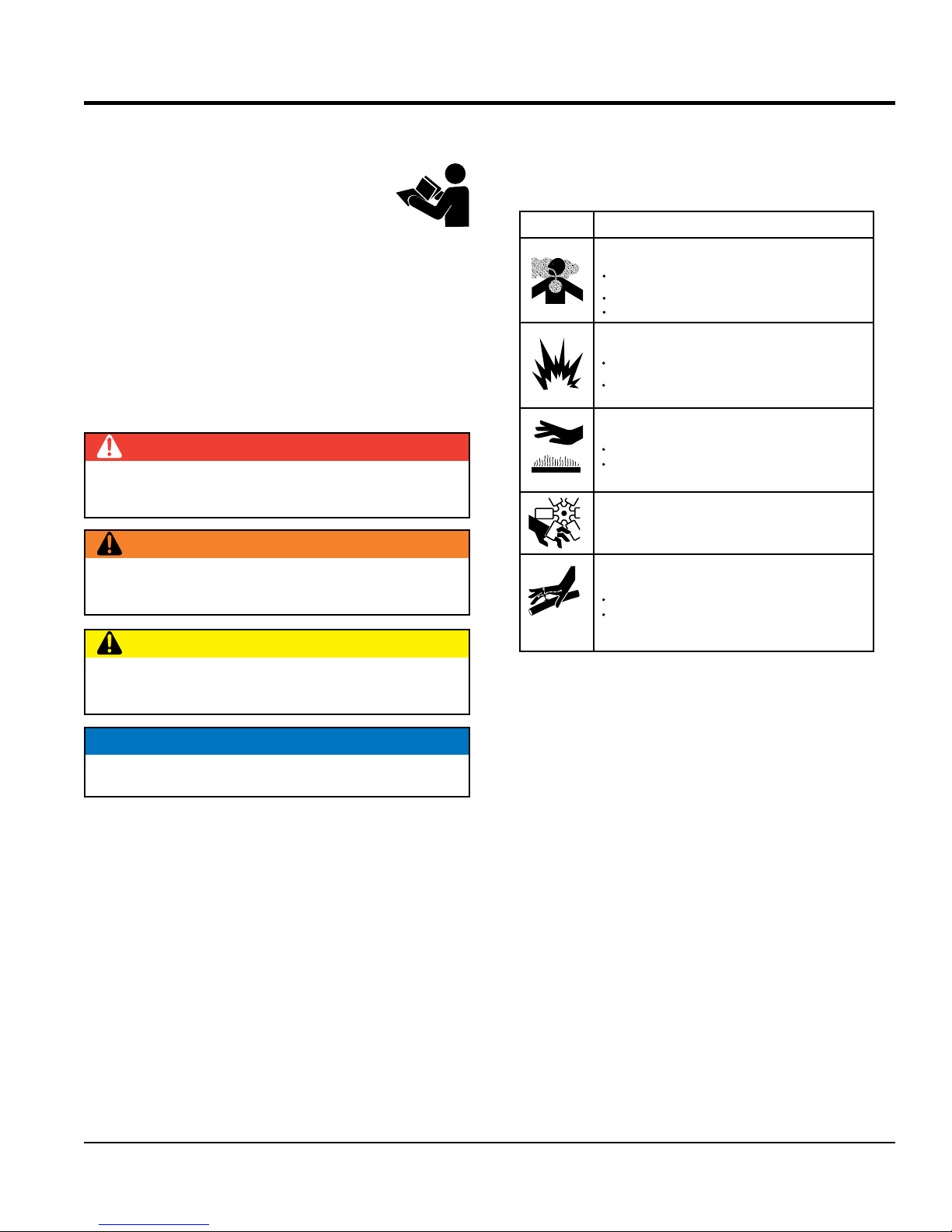
SAFETY MESSAGES
The four safety messages shown below will inform you
about potential hazards that could injure you or others. The
safety messages specifi cally address the level of exposure
to the operator and are preceded by one of four words:
DANGER, WARNING, CAUTION
SAFETY SYMBOLS
Potential hazards associated with the operation of this
equipment will be referenced with hazard symbols which
may appear throughout this manual in conjunction with
safety messages.
or NOTICE.
DANGER
Indicates a hazardous situation which, if not avoided,
WILL result in DEATH or SERIOUS INJURY.
WARNING
Indicates a hazardous situation which, if not avoided,
COULD result in DEATH or SERIOUS INJURY.
CAUTION
SYMBOL
Inhaling exhaust fumes can result in severe
injury or death.
Only operate equipment in well ventilated areas.
DO NOT inhale exhaust gases/fumes.
Gasoline fuel can cause fire or explosion. Stop
engine before refueling.
Keep cigarettes, sparks and flames away from hot
surfaces.
HOT PARTS can burn skin.
DO NOT touch hot parts. Allow machine a sufficient
amount of time to cool before performing maintenance.
Keep hands clear of rotating parts at all times.
HOT FLUID can burn skin.
DO NOT allow skin to come in contact with hot fluid.
Allow machine a sufficient amount of time to cool
before performing maintenance.
SAFETY HAZARD
WARNING
Lethal Exhaust Gas Hazard
WARNING
Explosive Fuel Hazard
CAUTION
Burn Hazard
WARNING
Rotating Parts Hazard
CAUTION
Burn Hazard
Indicates a hazardous situation which, if not avoided,
COULD result in MINOR or MODERATE INJURY.
NOTICE
Addresses practices not related to personal injury.
GENERAL SAFETY
WBH-16EF CE POWER BUGGY • OPERATION AND PARTS MANUAL — REV. #0 (09/19/18) — PAGE 5
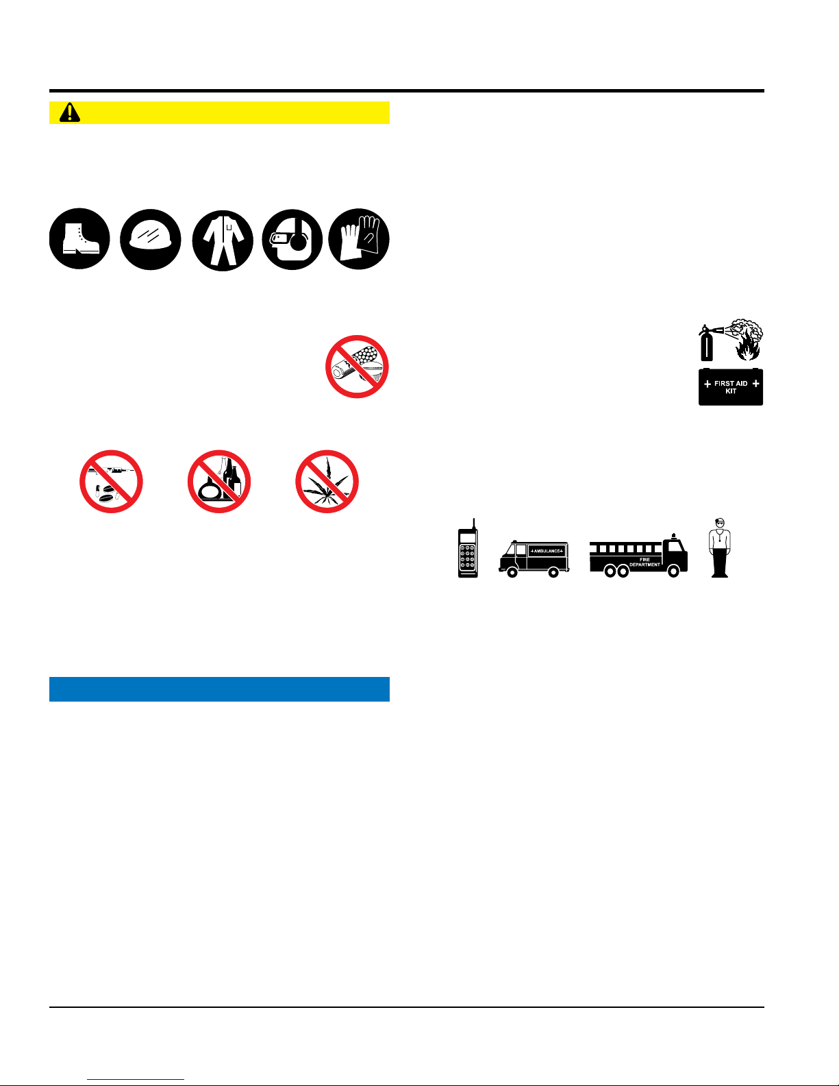
SAFETY INFORMATION
CAUTION
This equipment should only be operated by trained and
Whenever necessary, replace nameplate, operation and
Manufacturer does not assume responsibility for any
accident due to equipment modifi cations. Unauthorized
use accessories or attachments that are not
recommended by Multiquip for this equipment. Damage
keep
Also, know the phone numbers
fi re department.
This information will be invaluable in the case of an
NEVER operate this equipment without proper protective
clothing, shatterproof glasses, respiratory protection,
hearing protection, steel-toed boots and other protective
devices required by the job or city and state regulations.
Avoid wearing jewelry or loose fi tting clothes that may
snag on the controls or moving parts as this can cause
serious injury.
NEVER operate this equipment when not
feeling well due to fatigue, illness or when
under medication.
NEVER operate this equipment under the
infl uence of drugs or alcohol.
ALWAYS clear the work area of any debris, tools, etc.
that would constitute a hazard while the equipment is
in operation.
No one other than the operator is to be in the working
area when the equipment is in operation.
DO NOT use the equipment for any purpose other than
its intended purposes or applications.
qualifi ed personnel 18 years of age and older.
safety decals when they become diffi cult read.
equipment modifi cation will void all warranties.
NEVER
to the equipment and/or injury to user may result.
ALWAYS know the location of the nearest
fi re extinguisher.
ALWAYS know the location of the nearest
fi rst aid kit.
ALWAYS know the location of the nearest phone or
a phone on the job site.
of the nearest ambulance, doctor and
emergency.
POWER BUGGY SAFETY
NOTICE
PAGE 6 — WBH-16EF CE POWER BUGGY • OPERATION AND PARTS MANUAL — REV. #0 (09/19/18)
SAFETY INFORMATION
inspect the surface over which you will travel.
Look for holes, drop-offs and obstacles. Look for rough
and weak spots on docks, ramps or fl oor. Look for oil
spills, wet spots and slippery surfaces. Look for soft soil,
deep mud and standing water. Watch for anything that
might make you lose control or cause the power buggy
clear away trash and debris. Pick up anything
make sure aisles, ramps, doorways and
plan your work. Make sure you know where
you will make your pickups, dumps and turns. Before
operate the power buggy on unsafe haul roads,
operate power buggy on excessive slopes with
operate power buggy on extremely uneven
allow riders other than the operator on the
secure the step plate (platform) in the upright
position when using the power buggy over rough terrain.
stand on the power buggy step plate (platform)
when walking in rough terrain. Walk behind the power buggy.
touch, lean on or reach through the dump
climb on
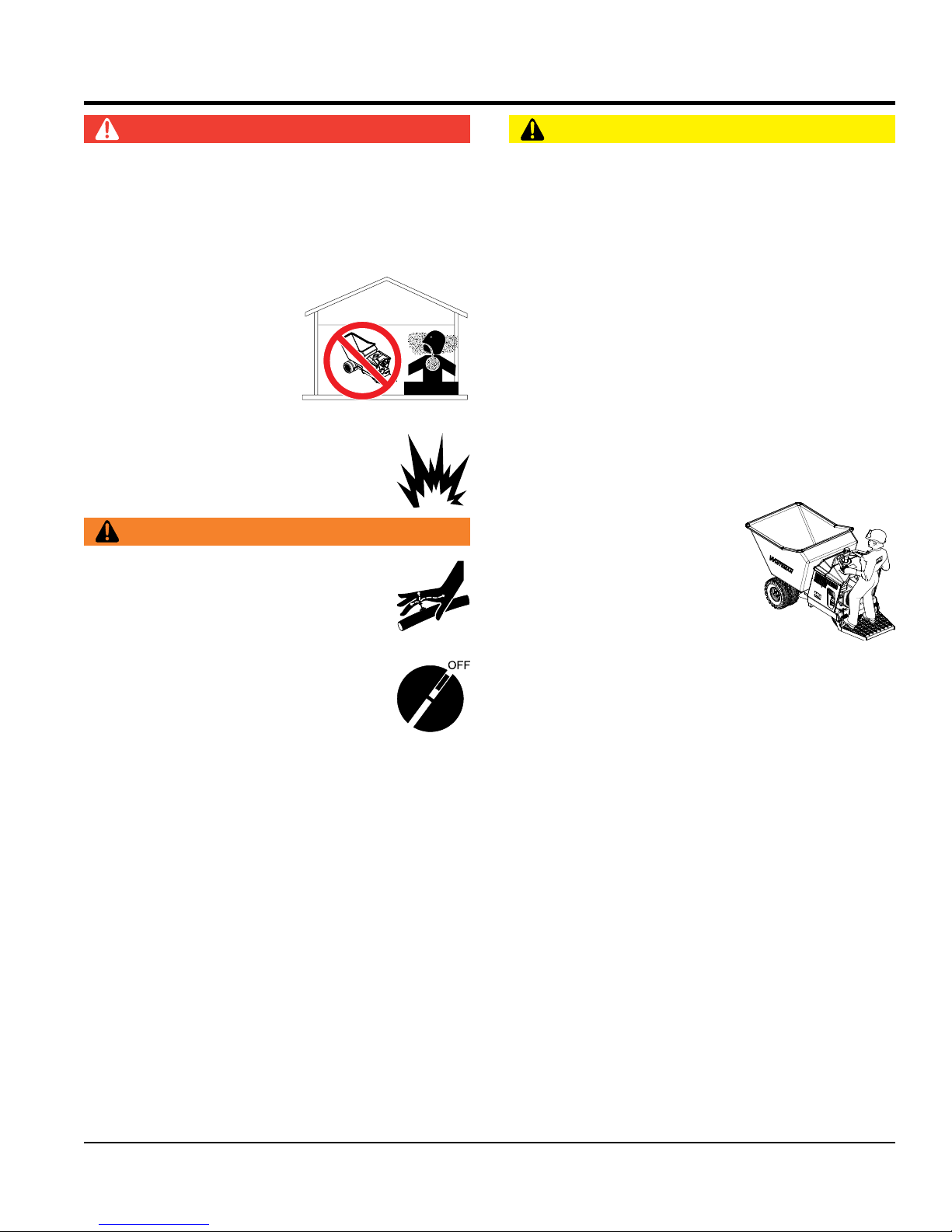
DANGER
Engine fuel exhaust gases contain poisonous carbon
monoxide. This gas is colorless and odorless, and can
cause death if inhaled.
The engine of this equipment requires an adequate free
fl ow of cooling air. NEVER operate this equipment in any
enclosed or narrow area
where free fl ow of the air is
restricted. If the air fl ow is
restricted it will cause injury
to people and property and
serious damage to the
DANGEROUS
GAS FUMES
equipment or engine.
NEVER operate the equipment in an explosive
atmosphere or near combustible materials. An
explosion or fi re could result causing severe
bodily harm or even death.
WARNING
NEVER use your hand to fi nd hydraulic leaks.
Use a piece of wood or cardboard. Hydraulic
fl uid injected into the skin must be treated by
a knowledgeable physician immediately or
severe injury or death can occur.
Accidental starting can cause severe injury
or death. ALWAYS place the ON/OFF
switch in the OFF position.
CAUTION
ALWAYS
to tip over.
ALWAYS
that might puncture the tires.
ALWAYS
passages are clear.
ALWAYS
you take a load, know where you will place it.
NEVER operate the power
buggy facing backwards. In
a backwards position, the
operator cannot properly
activate the manual brake,
emergency switch, grip the
handles or steer the machine.
ALWAYS face in the direction
of the bucket.
DO NOT
load areas, and dump areas.
WBH16
NEVER disconnect any emergency or safety devices.
These devices are intended for operator safety.
Disconnection of these devices can cause severe injury,
bodily harm or even death. Disconnection of any of these
devices will void all warranties.
NEVER approach power lines with any part of the
buggy unless all local, state/provincial and federal
(OSHA) required safety precautions have been taken.
Use extreme caution when approaching high voltage
power lines.
WBH-16EF CE POWER BUGGY • OPERATION AND PARTS MANUAL — REV. #0 (09/19/18) — PAGE 7
DO NOT
a grade higher than 10% (6°), forward and backward.
DO NOT
surfaces.
NEVER
power buggy.
ALWAYS
DO NOT
DO NOT
mechanism or permit others to do so. NEVER
the power buggy or dump mechanism.

DO NOT operate the power buggy at excessive speeds.
Reckless operation may cause accidents and severe
injury. Slow down when approaching people, wet areas,
and going up and down grades. It is the responsibility of
the operator to adjust speed, as necessary, depending
on the conditions of the road or path.
ALLOW extra time to stop when operating the power
buggy ion wet surfaces or loosely graded materials.
DO NOT dump materials that are large and chunky.
These types of material may shift causing the power
buggy to tip and throw the operator off the machine. The
power buggy is intended for dumping free-fl owing and
loose materials such as dry soil, slag, and wet concrete.
DO NOT dump materials from bucket while the power
buggy is moving.
For walk behind operation, the operator platform must be
stowed and locked in the up position. The speed should
also be reduced to 3 mph (4.8 kph) or slower.
NOTICE
ALWAYS ensure power buggy is
appropriate blocks or jackstands when performing
maintenance requires elevation of the buggy.
ALWAYS make sure the power buggy’s brakes are
working properly. Check brake linkage and adjust as
required. NEVER operate the power buggy with a
defective braking system.
Ensure brakes are applied when leaving or when using
on a slope.
When parking on a slope, position the power buggy at
a right angle to a slope. Ensure that the parking brake
is engaged and holds the power buggy safely in place
when parking on a slope.
When filling or dumping
capacity of power buggy.
ALWAYS be aware of traveling conditions. Reduce load
if necessary.
DO NOT activate dump mechanism (tub) if buggy is
facing a down hill slope.
DO NOT stand in front or along side the buggy when
discharging a load.
ALWAYS block the power buggy with appropriate blocks
when leaving the power buggy parked on a slope.
To prevent unexpected loss of control, DO NOT start
engine on a sloping surface.
Ensure that the speed control lever works freely and
start engine
unless speed control linkage is working properly.
Make sure that the tires are infl ated to the manufacturer’s
operate the power buggy with bad or worn tires.
replace defective tires with new ones.
make sure the hydraulic dumping mechanism
Avoid sudden stops and starts and changes in direction.
jerk the steering
attempt to work the control except from the
drive or tow the power buggy in traffi c or on
keep the machine in proper running condition.
Fix damage to machine and replace any broken parts
The entire power buggy (tub, step plate, shroud, wheels,
etc.) should be cleaned after every use. Make sure there
is no buildup of concrete, grease, oil or debris on the
store equipment properly when it is not being
used. Equipment should be stored in a clean, dry location
out of the reach of children and unauthorized personnel.
OFF position
DO NOT operate the power buggy at excessive speeds.
DO NOT stand in front or along side the buggy when
block the power buggy with appropriate blocks
start
Ensure that the speed control lever works freely and
start engine
Make sure that the tires are infl ated to the manufacturer’s
operate the power buggy with bad or worn tires.
make sure the hydraulic dumping mechanism
Avoid sudden stops and starts and changes in direction.
jerk the steering
attempt to work the control except from the
drive or tow the power buggy in traffi c or on
Fix damage to machine and replace any broken parts
The entire power buggy (tub, step plate, shroud, wheels,
etc.) should be cleaned after every use. Make sure there
is no buildup of concrete, grease, oil or debris on the
store equipment properly when it is not being
used. Equipment should be stored in a clean, dry location
out of the reach of children and unauthorized personnel.
position
returns to the closed position. DO NOT
recommended tire pressure.
NEVER
ALWAYS
ALWAYS
of the tub is working properly.
Operate the controls smoothly. DO NOT
or any other controls.
securely placed on
NEVER
operator’s position.
NEVER
public roads.
ALWAYS
immediately.
machine.
ALWAYS
DO NOT exceed payload
ALWAYS place the fuel valve lever in the
when the equipment is not in use.
Reckless operation may cause accidents and severe
injury. Slow down when approaching people, wet areas,
and going up and down grades. It is the responsibility of
the operator to adjust speed, as necessary, depending
on the conditions of the road or path.
ALLOW extra time to stop when operating the power
buggy ion wet surfaces or loosely graded materials.
DO NOT dump materials that are large and chunky.
These types of material may shift causing the power
buggy to tip and throw the operator off the machine. The
power buggy is intended for dumping free-fl owing and
loose materials such as dry soil, slag, and wet concrete.
DO NOT dump materials from bucket while the power
buggy is moving.
For walk behind operation, the operator platform must be
stowed and locked in the up position. The speed should
also be reduced to 3 mph (4.8 kph) or slower.
NOTICE
ALWAYS ensure power buggy is securely placed on
appropriate blocks or jackstands when performing
maintenance requires elevation of the buggy.
ALWAYS make sure the power buggy’s brakes are
working properly. Check brake linkage and adjust as
required. NEVER operate the power buggy with a
defective braking system.
Ensure brakes are applied when leaving or when using
on a slope.
SAFETY INFORMATION
discharging a load.
ALWAYS
when leaving the power buggy parked on a slope.
To prevent unexpected loss of control, DO NOT
engine on a sloping surface.
returns to the closed position. DO NOT
unless speed control linkage is working properly.
recommended tire pressure.
NEVER
ALWAYS replace defective tires with new ones.
ALWAYS
of the tub is working properly.
Operate the controls smoothly. DO NOT
or any other controls.
NEVER
operator’s position.
NEVER
public roads.
ALWAYS keep the machine in proper running condition.
immediately.
When parking on a slope, position the power buggy at
a right angle to a slope. Ensure that the parking brake
is engaged and holds the power buggy safely in place
when parking on a slope.
When filling or dumping DO NOT exceed payload
capacity of power buggy.
ALWAYS be aware of traveling conditions. Reduce load
if necessary.
DO NOT activate dump mechanism (tub) if buggy is
facing a down hill slope.
PAGE 8 — WBH-16EF CE POWER BUGGY • OPERATION AND PARTS MANUAL — REV. #0 (09/19/18)
machine.
ALWAYS
ALWAYS place the fuel valve lever in the OFF
when the equipment is not in use.
ENGINE SAFETY
FUEL SAFETY
ALWAYS use extreme caution when working with
fi ll the fuel tank while the engine is running
overfi ll tank and tighten fuel cap until you hear
"clicking", since spilled fuel could ignite if it comes into
contact with hot engine parts or sparks from the ignition
Store fuel in appropriate containers, in well-ventilated
leave the power buggy in the vicinity of ovens,
furnaces or radiant heaters. Heat could raise the
drop the battery. There is a possibility that the
keep the battery charged. If the battery is not
charge battery if frozen. Battery can explode.
When frozen, warm the battery to at least 61°F (16°C).
DO NOT place hands or fingers inside
engine compartment when engine is
running.
NEVER operate the engine with heat shields or
guards removed.
Keep fi ngers, hands hair and clothing away
from all moving parts to prevent injury.
ALWAYS shut down the engine before
performing service or maintenance.
DO NOT remove the engine oil drain plug while the
engine is hot. Hot oil will gush out of the oil tank and
severely scald any persons in the general area of the
power buggy.
WARNING
SAFETY INFORMATION
fl ammable liquids.
DO NOT
or hot.
DO NOT
system.
areas and away from sparks and fl ames.
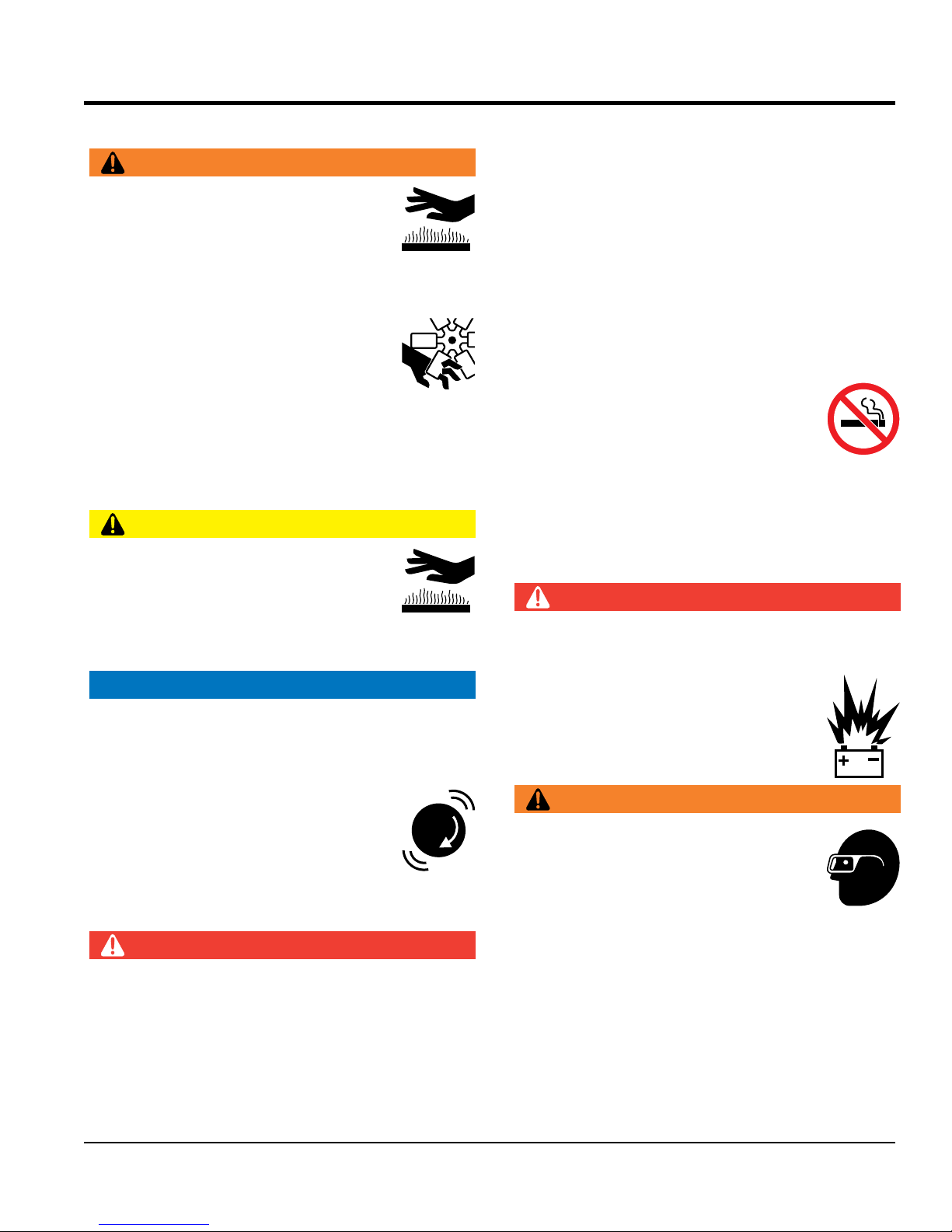
NEVER use fuel as a cleaning agent.
DO NOT smoke around or near the equipment.
Fire or explosion could result from fuel vapors
or if fuel is spilled on a hot engine.
DO NOT
CAUTION
NEVER touch the hot exhaust manifold,
muffl er or cylinder. Allow these parts to cool
before servicing equipment.
Make certain the operator knows how to and is capable
of turning the engine OFF in case of an emergency.
NOTICE
NEVER run engine without an air fi lter or with a dirty air
fi lter. Severe engine damage may occur. Service air fi lter
frequently to prevent engine malfunction.
NEVER tamper with the factory settings
of the engine or engine governor. Damage
to the engine or equipment can result
if operating in speed ranges above the
maximum allowable.
DANGER
pressure of the fuel so that vented gas could ignite.
BATTERY SAFETY
DANGER
DO NOT
battery will explode.
DO NOT expose the battery to open fl ames,
sparks, cigarettes, etc. The battery contains
combustible gases and liquids. If these
gases and liquids come into contact with a
fl ame or spark, an explosion could occur.
WARNING
ALWAYS wear safety glasses when
handling the battery to avoid eye irritation.
The battery contains acids that can cause
injury to the eyes and skin.
Use well-insulated gloves when picking up
the battery.
DO NOT start the engine near spilled fuel or combustible
fl uids. Fuel is extremely fl ammable and its vapors can
cause an explosion if ignited.
ALWAYS refuel in a well-ventilated area, away from
sparks and open fl ames.
WBH-16EF CE POWER BUGGY • OPERATION AND PARTS MANUAL — REV. #0 (09/19/18) — PAGE 9
ALWAYS
charged, combustible gas will build up.
DO NOT
ALWAYS recharge the battery in a well-ventilated
environment to avoid the risk of a dangerous concentration
LIFTING SAFETY
TRANSPORTING SAFETY
Tighten fuel tank cap securely and close fuel cock to
When transporting of the power buggy is required, place
the power buggy on a fl at bed truck or equivalent and
make sure all tie-downs and block are in
place and the bucket is completely lowered in the fl at
underneath wheel to prevent rolling.
When transporting the power buggy on a truck or trailer,
know the overall height to avoid contacting overhead
obstructions such as bridges and power lines. Check
position
of combustible gases.
SAFETY INFORMATION
NOTICE
If the battery liquid (dilute sulfuric acid)
comes into contact with clothing or skin,
rinse skin or clothing immediately with
plenty of water.
If the battery liquid (dilute sulfuric acid) comes into
contact with eyes, rinse eyes immediately with plenty
of water and contact the nearest doctor or hospital to
seek medical attention.
CAUTION
ALWAYS disconnect the NEGATIVE battery terminal
before performing service on the equipment.
ALWAYS keep battery cables in good working condition.
Repair or replace all worn cables.
CAUTION
NEVER allow any person or animal to stand underneath
the equipment while lifting.
NOTICE
When lifting of the power buggy is required, use a
properly rated forklift. Forklift pockets are provided on
the power buggy's frame. Make sure the forklift arms are
insert into the power buggy's fork lift pockets a minimum
of 24-inches. Before lifting, make sure that the lifting bale
is not damaged.
ALWAYS shutdown engine before transporting.
prevent fuel from spilling.
tie down securely.
ALWAYS
(horizontal) position and securely latched.
Place chock blocks
the truck and ramp capacities.
ALWAYS place the fuel valve lever in the OFF
when the before transporting.
NEVER tip the engine to extreme angles during lifting as
it may cause oil to gravitate into the cylinder head, making
the engine start diffi cult.
DO NOT lift machine to unnecessary heights.
NEVER lift the equipment while the engine is running.
ALWAYS use ramps capable of supporting the weight
of the power buggy and the operator to load and unload
the power buggy.
PAGE 10 — WBH-16EF CE POWER BUGGY • OPERATION AND PARTS MANUAL — REV. #0 (09/19/18)

SAFETY INFORMATION
ENVIRONMENTAL SAFETY/DECOMMISSIONING
Decommissioning is a controlled process used to safely
retire a piece of equipment that is no longer serviceable.
If the equipment poses an unacceptable and unrepairable
safety risk due to wear or damage or is no longer cost
effective to maintain (beyond life-cycle reliability) and is to
be decommissioned (demolition and dismantlement),be
sure to follow rules below.
EMISSIONS INFORMATION
This equipment conforms with applicable Environmental
Protection Agency (EPA) and California Air Resources
The gasoline engine used in this equipment has been
designed to reduce harmful levels of carbon monoxide
(CO), hydrocarbons (HC) and nitrogen oxides (NOx)
Fuel and vapor recovery hoses, EPA certifi ed SAE J30R7
Tampering with or altering the emission control system may
increase emissions beyond the legal limit. Do not remove
Additionally, modifying the fuel system may adversely affect
evaporative emissions, resulting in fi nes or other penalties.
The Emission control system is valid only for the United
States, its territories and commonwealths to include
The emission control label is an integral part of the emission
If a replacement emission label is needed, please contact
NOTICE
DO NOT pour waste or oil directly onto the ground, down
a drain or into any water source.
Contact your country's Department of
Public Works or recycling agency in your
area and arrange for proper disposal of
any electrical components, waste or oil
associated with this equipment.
When the life cycle of this equipment is over, remove
battery (if equipped) and bring to appropriate facility for
lead reclamation. Use safety precautions when handling
batteries that contain sulfuric acid.
When the life cycle of this equipment is over, it is
recommended that the unit frame and all other metal
parts be sent to a recycling center.
NOTICE
Board (CARB) emission regulations.
contained in gasoline exhaust emissions.
Mandated Emission Components:
Engine, EPA certifi ed
Fuel cap, EPA certifi ed
or SAE J30R14T2
Charcoal canister, EPA certifi ed
Miscellaneous Parts Associated with Emission System:
Hose clamps and retainer brackets
Roll over valve vapor recovery valve
Steel fuel tank
Metal recycling involves the collection of metal from
discarded products and its transformation into raw
materials to use in manufacturing a new product.
Recyclers and manufacturers alike promote the process
of recycling metal. Using a metal recycling center
promotes energy cost savings.
or alter any part of the system.
Canada.
Emission Control Label
system and is strictly controlled by regulation(s).
The label must remain with the engine for its entire life.
your authorized engine distributor.
WBH-16EF CE POWER BUGGY • OPERATION AND PARTS MANUAL — REV. #0 (09/19/18) — PAGE 11

SPECIFICATIONS (BUGGY)
Table 1. Specifications (Power Buggy)
Models WBH-16EF CE
Maximum Weight Capacity
(Dual Wheels)
Maximum Weight Capacity
(Single Wheels)
Operating Weight 1,415 lbs. (641.8 kg.)
Bucket/Tub Capacity 16 cu. ft. Water Level (.59 cu. yd.)
Bucket/Tub Material Polyethylene
Drive Hydrostatic
Speed Up to 7.25 mph. (11.67 km/h)
Steering Handle Bars To Rear Wheels
Fuel Tank Capacity 4.8 gallons (18.1 liters)
Hydraulic Oil Tank Capacity 5.3 gallons (20.4 liters)
Hydraulic Oil Type Exxon/Mobil Nuto H 46 or Equivalent.
Hydraulic Filter 10 Micron
Brakes (Drive Wheels) Dynamic Hydrostatic
Parking Brake (Drive Wheels) Mechanical
Dump Control Hydraulic Dump and Return
Discharge Height 6.0 in. (152 mm)
2,500 lbs. (1,134 kg)
1,100 lbs. (500 kg)
Ground Clearance 6.0 in. (152 mm)
Gradeability 6° or 10%
12V BCI Group U1, 300 CCA @ 0°F
Battery (LxWxH)
Foam Filled Tires (Drive Wheels)
Foam Filled Tires (Steering)
PAGE 12 — WBH-16EF CE POWER BUGGY • OPERATION AND PARTS MANUAL — REV. #0 (09/19/18)
7.75 x 5.18 x 7.31 in.
(197 x 132 x 186 mm)
5.70 x 8.0
(145 x 203 x 483 mm)
4.80 x 8.0 in.
(122 x 203 mm)

NOISE AND VIBRATION/ENGINE SPECIFICATIONS
Table 2. Noise and Vibration Emissions
Model
Guaranteed ISO 11201:2010 Based
Sound Pressure Level at Operator Station in dB(A)
Guaranteed ISO 3744:2010 Based
Sound Power Level in dB(A)
Sound Pressure Level Horn in dB(A)
2
Hand Arm Vibration Per ISO 2631-1:1997+A1:2010 in m/s
SA(8) 1.28 m/s
Whole Body Vibration Per ISO 2631-1:1997+A1:2010 in m/s2 SA(8) 0.05 m/s
NOTES:
1. Sound Pressure and Power Levels are “A” weighted Measures per ISO 226:2003 (ANSI S1.4-1981). They are measured with the operating
condition of the machine which generates the most repeatable but highest values of the sound levels. Under normal circumstances, the sound
level will vary depending on the condition of the material being worked upon.
2. The vibration level indicated is the vector sum of the RMS (Root Mean Square) Values of amplitudes on each axis, standardized to an 8 hour
exposure period, and obtained using operating condition of the machine that generates the most repeatable but highest values in accordance
with the applicable standards for the machine.
3. Per EU Directive 2002/44/EC, the daily exposure action value for hand arm vibration is 2.5 m/s2 SA(8). The daily exposure limit value is
5 m/s2 SA(8).
4. Per EU Directive 2002/44/EC, the daily exposure action value for whole body vibration is 0.5 m/s2 SA(8). The daily exposure limit value is
1.15 m/s2 SA(8).
WBH-16 CE
82.74
114
116
2
2
Table 3. Specifications (Engine)
Model GX390RT2QNB2 (Electric Start)
Type 4-Stroke Single Cylinder OHV
Bore X Stroke 3.46 x 2.51 in. (88 x 64 mm.)
Displacement 389 cc
Maximum Power 11.7 hp (3,600 rpm)
Maximum Torque 19.5 ft-lbs. (2.7 kg-m) @ 2,500 rpm
Compression Ratio 8.0:1
Idle Speed 1,400 ± rpm
Maximum No Load RPM 3.850 ± rpm
Specific Fuel Consumption 1 gal./hr. (3.78 liters/hr.)
Fuel Type Unleaded Gasoline Minimum 85 Octane
Crankcase Oil Capacity 1.16 qts. (1.1 liters)
Ignition Timing BTDC25
Starting System Electric
Air Cleaner Cyclone Type
Noise Level STD, OP 82.78 (S,S)
Dry Weight 68.3 lbs. (31.0 kg.)
Outside Dimensions L X W X H 15.9 x 17.7 x 17.4 in. (405 X 450 X 443 mm.)
WBH-16EF CE POWER BUGGY • OPERATION AND PARTS MANUAL — REV. #0 (09/19/18) — PAGE 13
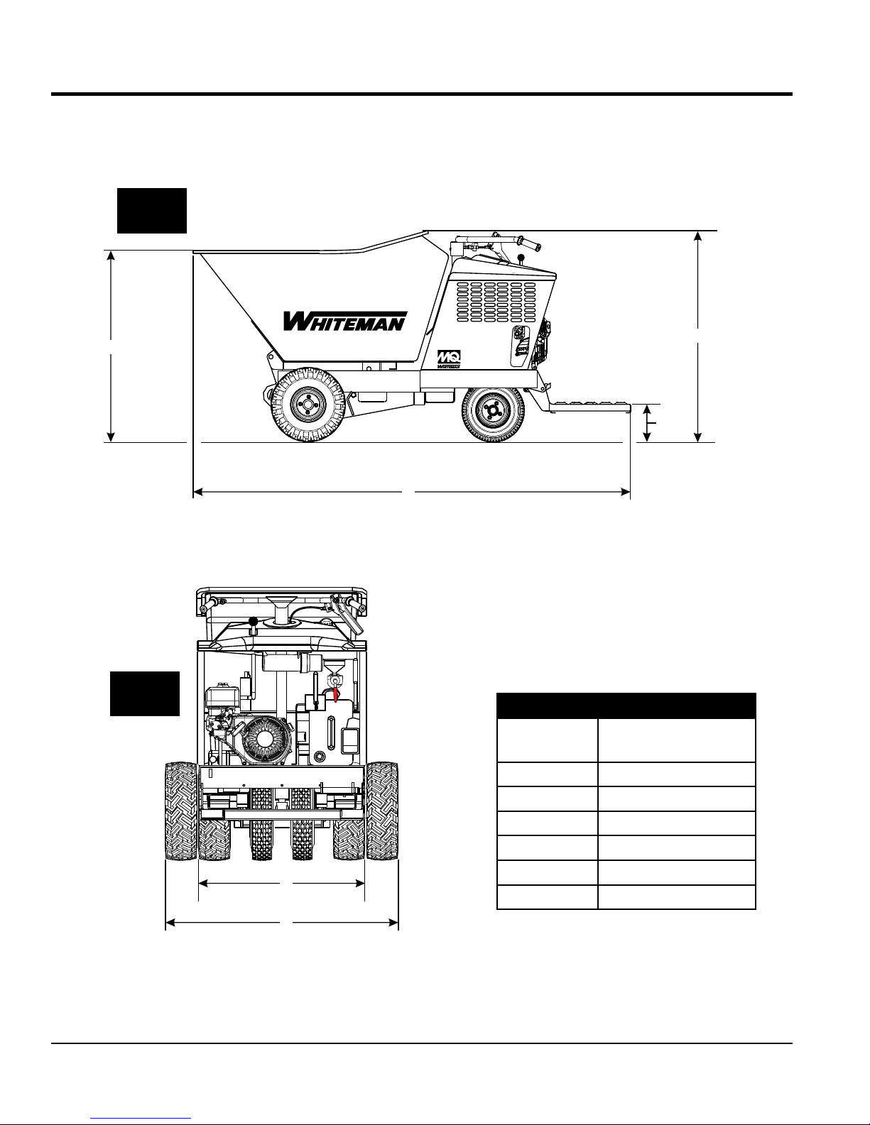
SIDE
VIEW
DIMENSIONS
A
REAR
VIEW
WBH-16
B
C
D
OFF
FUEL
ON
Table 4. Dimensions
Reference
Letter
Dimension
in. (mm)
E
F
Figure 1. WBH16EF CE Dimensions
PAGE 14 — WBH-16EF CE POWER BUGGY • OPERATION AND PARTS MANUAL — REV. #0 (09/19/18)
A 45.47 (1,155)
B 51.0 (1,295)
C 8.50 (216)
D 103 (2,612)
E 30.75 (781)
F 42.75 (1,085)
GENERAL INFORMATION
The MQ Whiteman Power Buggy, WBH-16EF CE (electric
start) is intended for the transportation of concrete, concrete
spreading and spot pouring. In addition, this power buggy
is designed for landscaping applications, material sub-base
distribution, job site cleanup and material transport.
The Power Buggy is equipped with a 6-inch dump height
which provides clearance and enables the operator to
maneuver over any form height. In addition, it has a unique
polyethylene tub design that reduces concrete splatter.
A low center of gravity has been incorporated into the
design which provides added safety when maneuvering
the buggy in tight areas. A 4.8 gallon (18.1 liters) fuel tank
allows for extended uninterrupted use. Maximum speed of
the power buggy is rated at 7.25 mph (11.7 km/h).
The maximum weight capacity of the Power Buggy is:
2,500 lbs. (1,134 kg) when dual wheels are employed and
1,100 lbs. (500 kg) when single wheels are used. The outer
wheels can be removed to allow the buggy to pass through
a 32 in. (81.28 cm.) door.
Hand and foot controls are provided for ease of dumping
and stopping of the power buggy. Multiple lift points have
been provided to allow for easy access of a forklift when
lifting is required.
The WBH-16EF CE is powered by a HONDA GX390 air
cooled gasoline engine rated at 11.7 HP at 3600 RPM
The engine drives a variable displacement hydrostatic
transmission which is activated by a cable controlled
hand lever. The hydraulic fluid flows to a divider valve
which directs the fluid to the forward reverse and dumping
systems.
The operator controls the forward and reverse machine
travel by manually shifting the control valve which directs
the hydraulic fluid flow to the two drive wheel motors. The
flow to the dump cylinder is also controlled by a manually
operated control valve.
This hydraulic system uses a parallel loop configuration,
operating at a maximum of 2100 PSI (14,478 kPa). The
system also features a neutral position which allows the
power buggy to be moved in the event of an emergency.
The hydraulic oil is filtered by a screen type filter located in
the hydraulic tank, then doubled filtered within the system
by a 10 micron cartridge spin-on return filter.
WARNING
All operators must have training before operating the
power buggy. For your safety, warnings are on the
machine and in this manual. Failure to obey these
warnings can cause severe injury or even death.
CAUTION
DO NOT attempt to operate the power
buggy until the Safety Information, General
Information, and Inspection sections of this
manual have been read and thoroughly
understood.
WBH-16EF CE POWER BUGGY • OPERATION AND PARTS MANUAL — REV. #0 (09/19/18) — PAGE 15
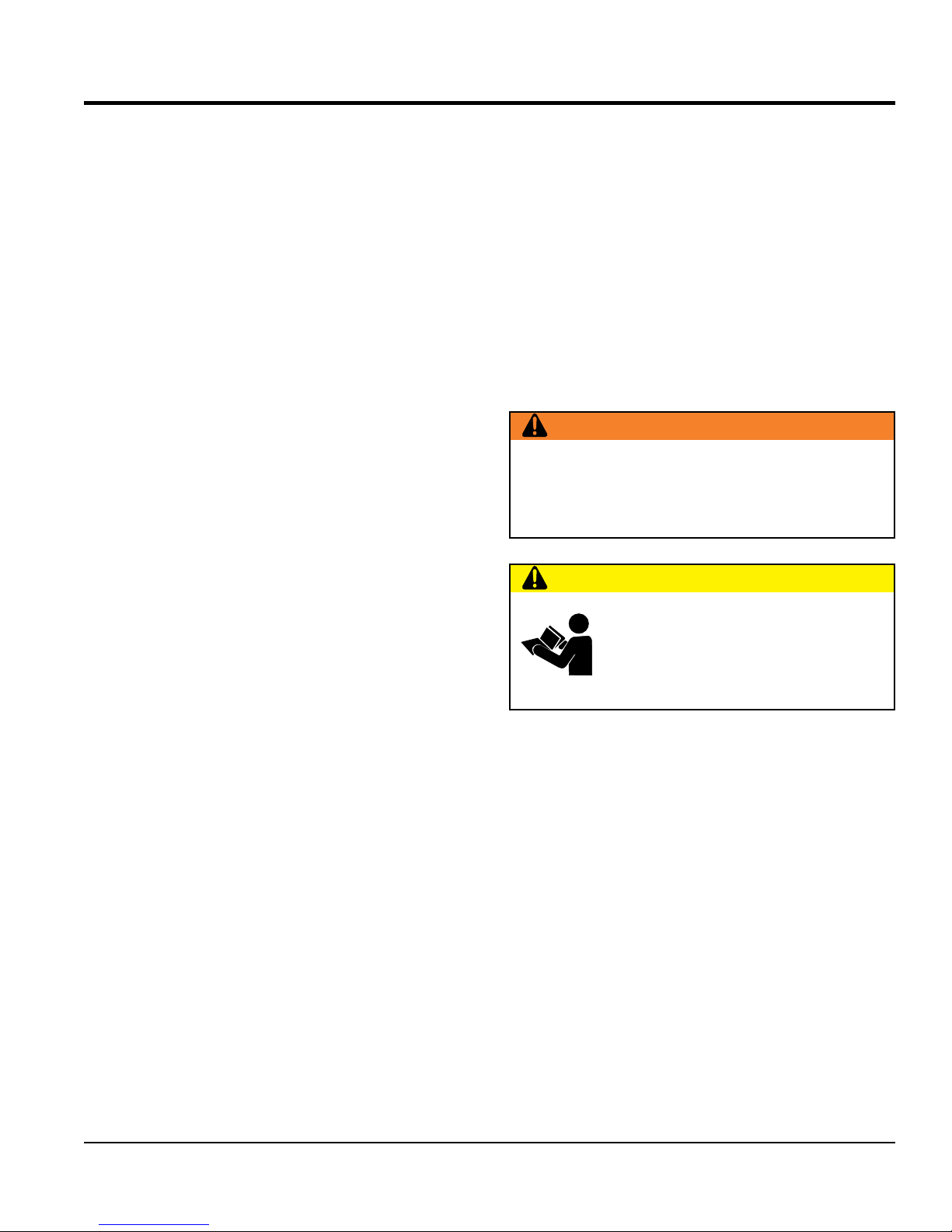
COMPONENTS
1
4
3
5
6
Figure 2. WBH-16EF Power Buggy Components
1. Tub or Bucket — Used for the transportation of
material. Tub holds approximately 16 cubic feet
(0.59 cubic yards) of water.
2. Horn Button — Press this button to activate the horn.
3. Handle Bar (Steering) — This handle bar is used
to steer the buggy. When driving the buggy, use both
hands and hold onto both handle bar grips.
4. Fuel Tank/Cap — Remove this cap to add fuel. Tank
holds approximately 4.8 U.S. gallons (18.1 liters). DO
NOT over fill. Tighten cap until you hear "clicking".
5. Fuel Valve Lever — When placed in the ON position
fuel will flow. OFF position stops fuel flow. ALWAYS
place this lever in the ON position when starting the
engine. When machine is not in use, place this lever
in the OFF position.
2
OFF
FUEL
ON
7
8
9
WBH16
10
11
12
13
14
8. Speed Control — Sets the power buggy's travel speed.
When fully depressed, the buggy will be at FULL speed.
When released, the buggy will STOP.
9. Travel Lever — When the travel lever is pushed
forward, the buggy will travel in the forward direction.
Placing the travel lever in the backward position will
cause the buggy to travel in the reverse direction.
Center position is neutral.
10. Parking Brake Lever — When this lever is activated
(pulled down), the parking brake will be set. To release
the brake, pull the lever upwards.
11. Horn — When activated sounds an audible alarm.
12. Hydraulic Tank/Cap — Remove this cap to add
hydraulic oil. Tank holds approximately 5.3 U.S. gallons
(20.4 liters). DO NOT over fill.
6. Kill Switch — In the event of an emergency, press this
button to stop the engine.
7. Documentation Canister — Store and maintain
Operation, Parts, and Engine manuals in this container
at all times.
PAGE 16 — WBH-16EF CE POWER BUGGY • OPERATION AND PARTS MANUAL — REV. #0 (09/19/18)
13. Brake Pedal — Press this pedal with the right foot to
stop the buggy.
14. Operator Platform — When the buggy is in use, the
operator shall ALWAYS stand on this platform while
holding onto the handle bar (steering).
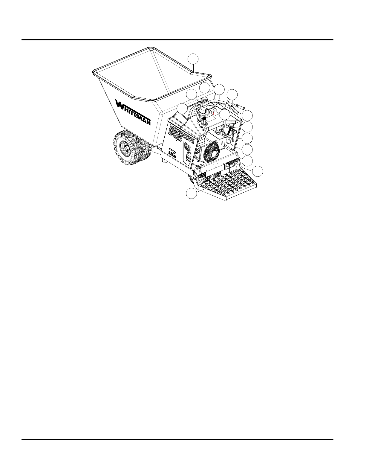
24
COMPONENTS CON'T
25
23
15
21
WBH16
16
22
20
19
18
17
Figure 3. WBH-16EF Power Buggy Components Continued
15. Dump Control Lever — Use this lever forward to place
the tub in the dump position (vertical), move the lever
backward to return the tub to travel position (horizontal).
16. Engine — This machine uses an electric start 11.7HP
Honda engine.
17. Dump Pedal — Use this pedal to place the tub in the
dump position (vertical). Press pedal a second time to
return tub to the travel position (horizontal).
18. Rear Tires — Unit uses foam-filled tires. Reference
Table 1 for tire specifications.
19. Muffler — Used to reduce noise and emissions.
NEVER touch the muffler while it is hot. Serious burns
can result.
20. Forklift Pockets — Use these fork lift pockets to lift
the power buggy with a forklift. Remember to insert the
forks of the fork lift a minimum of 24 inches (610 mm.)
into power buggy's fork lift pockets.
21. Fuse — 10 amp fuse that provides protection for the
horn circuit.
22. Charcoal Canister — Charcoal activated system
that absorbs or traps fuel vapors. Basic component
of evaporative emissions control systems.
23. Battery — Always use gloves and eye protection when
handling the battery.
24. Front Tires — Unit uses foam-filled tires. Reference
Table 1 for tire specifications.
25. Towing Hook — Use this hook to tow the buggy if it
gets stuck. This hook is NOT intended for towing the
buggy on public roads at high speeds.
WBH-16EF CE POWER BUGGY • OPERATION AND PARTS MANUAL — REV. #0 (09/19/18) — PAGE 17
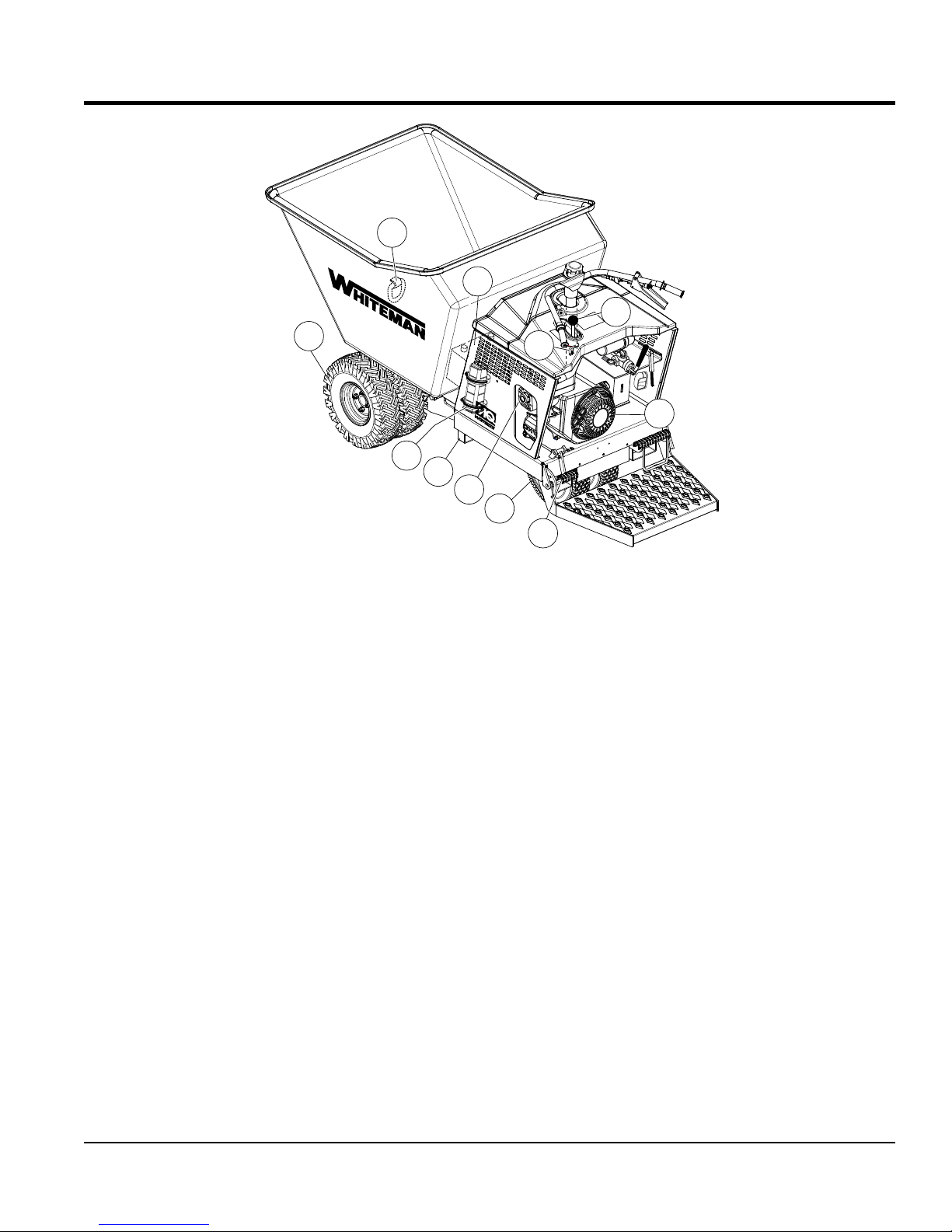
ENGINE COMPONENTS
9
10
8
7
6
5
4
Figure 4. Honda GX390 Engine
1
2
3
INITIAL SERVICING
The engine (Figure 4) must be checked for proper
lubrication and filled with fuel prior to operation. Refer to the
manufacturer's engine manual for instructions and details
of operation and servicing.
1. Throttle Lever – Used to adjust engine RPM speed.
2. Engine On/Off Switch – ON position permits engine
starting, OFF position stops engine operation. Not
installed on electric start models.
3. Recoil Starter (pull rope) – Manual-starting method.
Pull the starter grip until resistance is felt, then pull
briskly and smoothly. Not installed on electric start
models.
4. Fuel Valve Lever – OPEN to let fuel flow, CLOSE to
stop the flow of fuel.
5. Oil Drain Plug – Remove this plug to remove oil from
the engine's crankcase.
6. Dipstick/Oil Filler Cap – Remove this cap to determine
if the engine oil is low. Add oil through this filler port as
recommended in Table 5.
7. Choke Lever – Used in the starting of a cold engine,
or in cold weather conditions. The choke enriches the
fuel mixture.
8. Spark Plug – Provides spark to the ignition system.
Set spark plug gap according to engine manufacturer's
instructions. Clean spark plug once a week.
9. Muffler – Used to reduce noise and emissions. NEVER
touch when hot!
10. Air Cleaner – Prevents dirt and other debris from
entering the fuel system. Remove wing-nut on top of
air filter canister to gain access to filter element.
NOTICE
Operating the engine without an air filter, with a
damaged air filter, or a filter in need of replacement
will allow dirt to enter the engine, causing rapid engine
wear.
PAGE 18 — WBH-16EF CE POWER BUGGY • OPERATION AND PARTS MANUAL — REV. #0 (09/19/18)
BEFORE STARTING
1. Read all safety instructions at the beginning of manual.
INSPECTION
2. Clean the unit, removing dirt and dust, particularly the
engine cooling air inlet, carburetor and air cleaner.
3. Check the air filter for dirt and dust. If air filter is dirty,
replace air filter with a new one as required.
4. Check carburetor for external dirt and dust. Clean with
dry compressed air.
5. Check fastening nuts and bolts for tightness.
ENGINE OIL CHECK
1. To check the engine oil level, place the unit on secure
level ground with the engine stopped.
2. Remove the filler dipstick from the engine oil filler hole
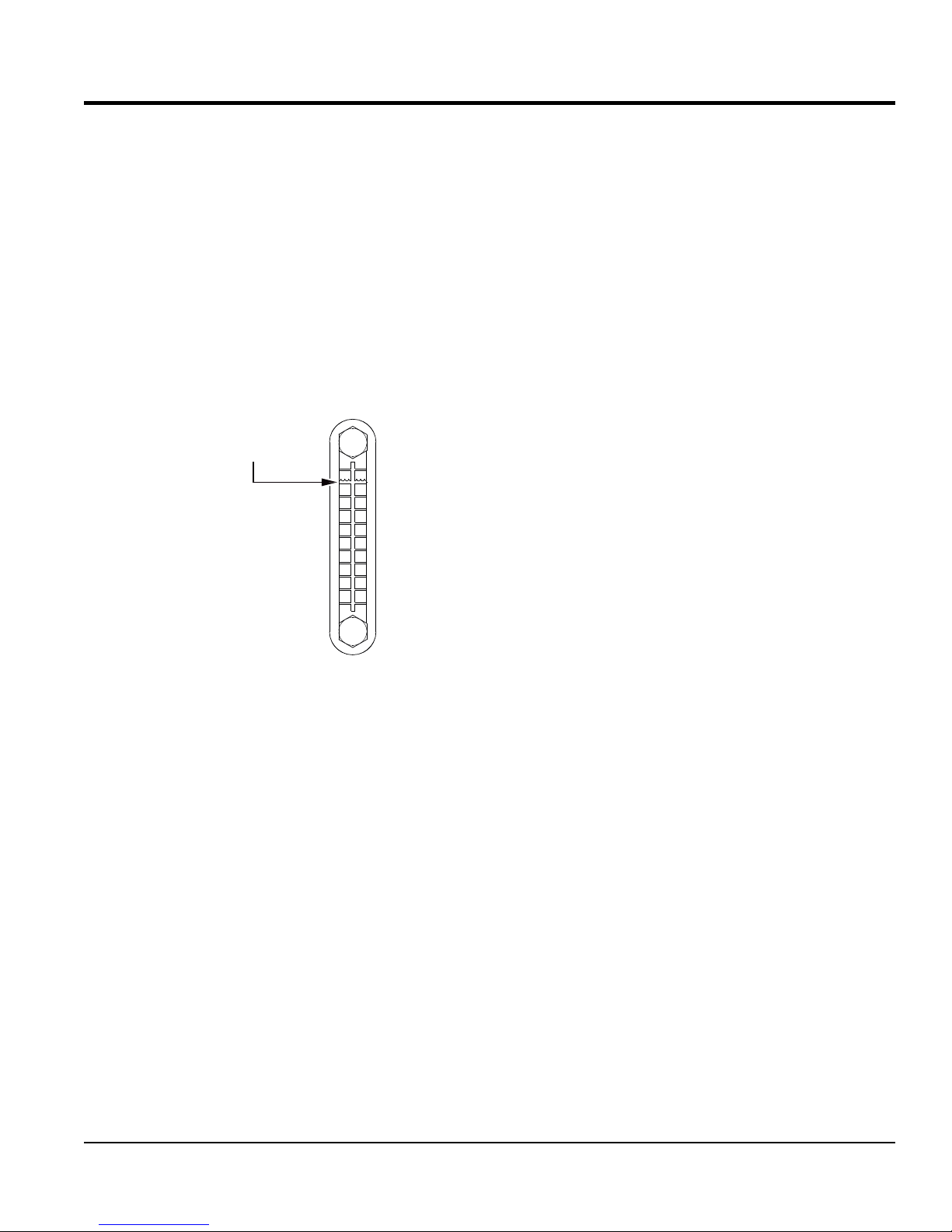
(Figure 5) and wipe it clean.
DIPSTICK
UPPER LIMIT
LOWER LIMIT
Figure 6. Engine Oil Dipstick (Oil Level)
Table 5. Engine Oil Type
Season Temperature Oil Type
Summer 25°C or Higher SAE 10W-30
Spring/Fall 25°C ~ 10°C SAE 10W-30/20
Winter 0°C or Lower SAE 10W-10
FUEL CHECK
DANGER
Motor fuels are highly flammable and can
be dangerous if mishandled. DO NOT
smoke while refueling. DO NOT attempt
to refuel the buggy if the engine is hot or
running.
Figure 5. Engine Oil Dipstick (Removal)
3. Insert and remove the dipstick without screwing it into
the filler neck. Check the oil level shown on the dipstick.
4. If the oil level is low (Figure 6), fill to the edge of the
oil filler hole with the recommended oil type (Table 5).
Maximum oil capacity is 1.16 quarts (1.1 liters).
5. When checking the engine oil, be sure to check if the oil
is clean. If the oil is not clean, drain the oil by removing
the oil drain plug, and refill with the specified amount
of oil as outlined in the maintanence section of this
manual. Oil should be warm before draining.
WBH-16EF CE POWER BUGGY • OPERATION AND PARTS MANUAL — REV. #0 (09/19/18) — PAGE 19
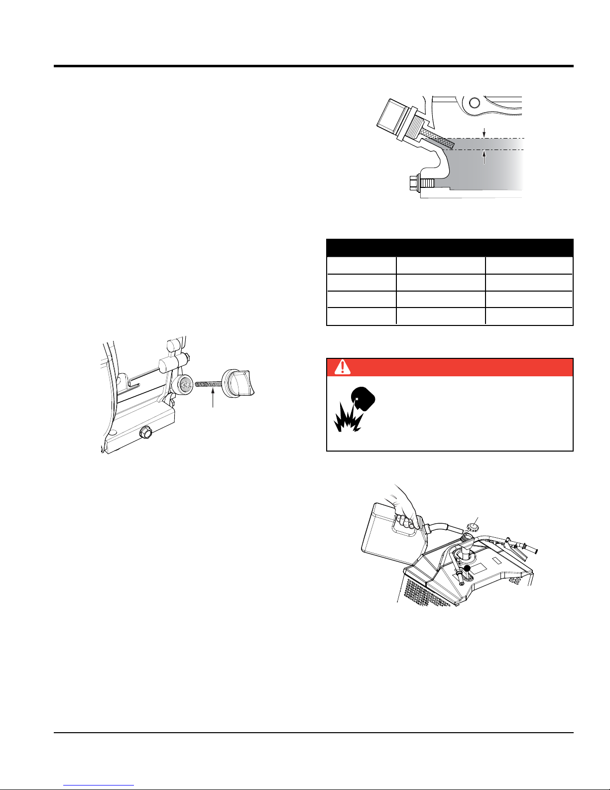
1. Remove the fuel cap (Figure 7) located on top of fuel
tank.
FUEL CAP
UNLEADED
GASOLINE
Figure 7. Fuel Tank
2. Visually inspect to see if fuel level is low. If fuel level is
low, replenish with unleaded fuel.
3. When refueling, be sure to use a strainer for filtration.
DO NOT top-off fuel. Wipe up any spilled fuel.
immediately. Reinstall fuel cap.
INSPECTION
BATTERY
This unit is of negative ground DO NOT connect in reverse.
ALWAYS maintain battery fluid level between the specified
marks. Battery life will be shortened, if the fluid level are
not properly maintained. Add only distilled water when
replenishment is necessary.
DO NOT over fill. Check to see whether the battery cables
are loose. Poor contact may result in poor starting or
malfunctions.
ALWAYS keep the terminals firmly tightened. Coating the
terminals with an approved battery terminal treatment
compound. Replace battery with only recommended type
battery. The battery type used in this power buggy is BCI
Group U1.
The battery is sufficiently charged if the specific gravity
of the battery fluid is 1.28 (at 68° F). If the specific gravity
should fall to 1.245 or lower, it indicates that the battery is
dead and needs to be recharged or replaced.
Before charging the battery with an external electric source,
be sure to disconnect the battery cables.
CAUTION
ALWAYS disconnect the negative terminal FIRST and
reconnect negative terminal LAST.
Battery Cable Installation
When connecting battery do the following:
1. NEVER connect the battery cables to the battery
terminals when the ignition is in the ON position (start).
2. Place a small amount of battery terminal treatment
compound around both battery terminals. This will
ensure a good connection and will help prevent
corrosion around the battery terminals.
NOTICE
If the battery cable is connected incorrectly, electrical
damage to the power buggy will occur. Pay close attention
to the polarity of the battery when connecting the battery.
CAUTION
Inadequate battery connections may cause poor
starting of the power buggy, and create other
malfunctions.
TIRE PRESSURE CHECK
The wheels and tires of the power buggy are very important
in its effective operation.
1. Check the tires regularly to make certain the lugs nuts
are tight
2. Make sure tires are inflated to manufacturer's
suggested tire pressure. DO NOT operate the buggy
with bad or worn tires.
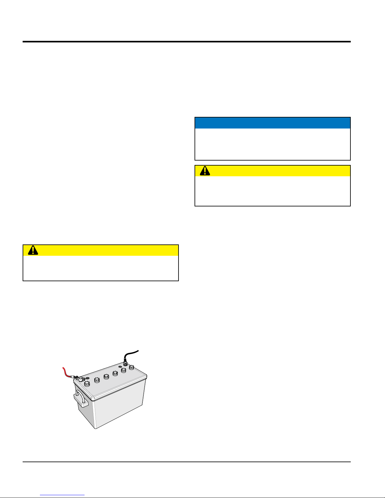
ALWAYS be sure the battery cables (Figure 8) are properly
connected to the battery terminals as shown below. The red
cable is connected to the positive terminal of the battery,
and the black cable is connected to the negative terminal
of the battery.
NEGATIVE
POSITIVE
Figure 8. Battery Connections
PAGE 20 — WBH-16EF CE POWER BUGGY • OPERATION AND PARTS MANUAL — REV. #0 (09/19/18)
PARKING BRAKE CHECK
Check the brakes as outlined in the maintenance section
of this manual.
LINKAGE CHECK
Check and make sure that all linkages within the buggy are
functioning correctly.
STEERING CHECK
1. Check and make sure that the power buggy's steering
turns freely and that there is no binding.
2. Make sure that the zerk fitting for the steering has
been lubricated.
DUMP CYLINDER CHECK
1. Check the power buggy's dump cylinder as outlined in
the operation section of this manual.
2. Make sure that both zerk fittings for the dump cylinder
have been lubricated.
HYDRAULIC OIL CHECK
3. Visually read the hydraulic sight glass (Figure 9) to see
if the hydraulic oil level is low.
4. If the hydraulic oil is low, add enough hydraulic oil to
bring oil level to a normal safe operating level.
NORMAL
OPERATING
LEVEL
INSPECTION
Figure 9. Hydraulic Sight Glass
WBH-16EF CE POWER BUGGY • OPERATION AND PARTS MANUAL — REV. #0 (09/19/18) — PAGE 21
CAUTION
FORWARD
NEUTRAL
REVERSE
OPEN
DO NOT attempt to operate the power
buggy until the Safety Information, General
Information, and Inspection sections of this
manual have been read and thoroughly
understood.
ELECTRIC START
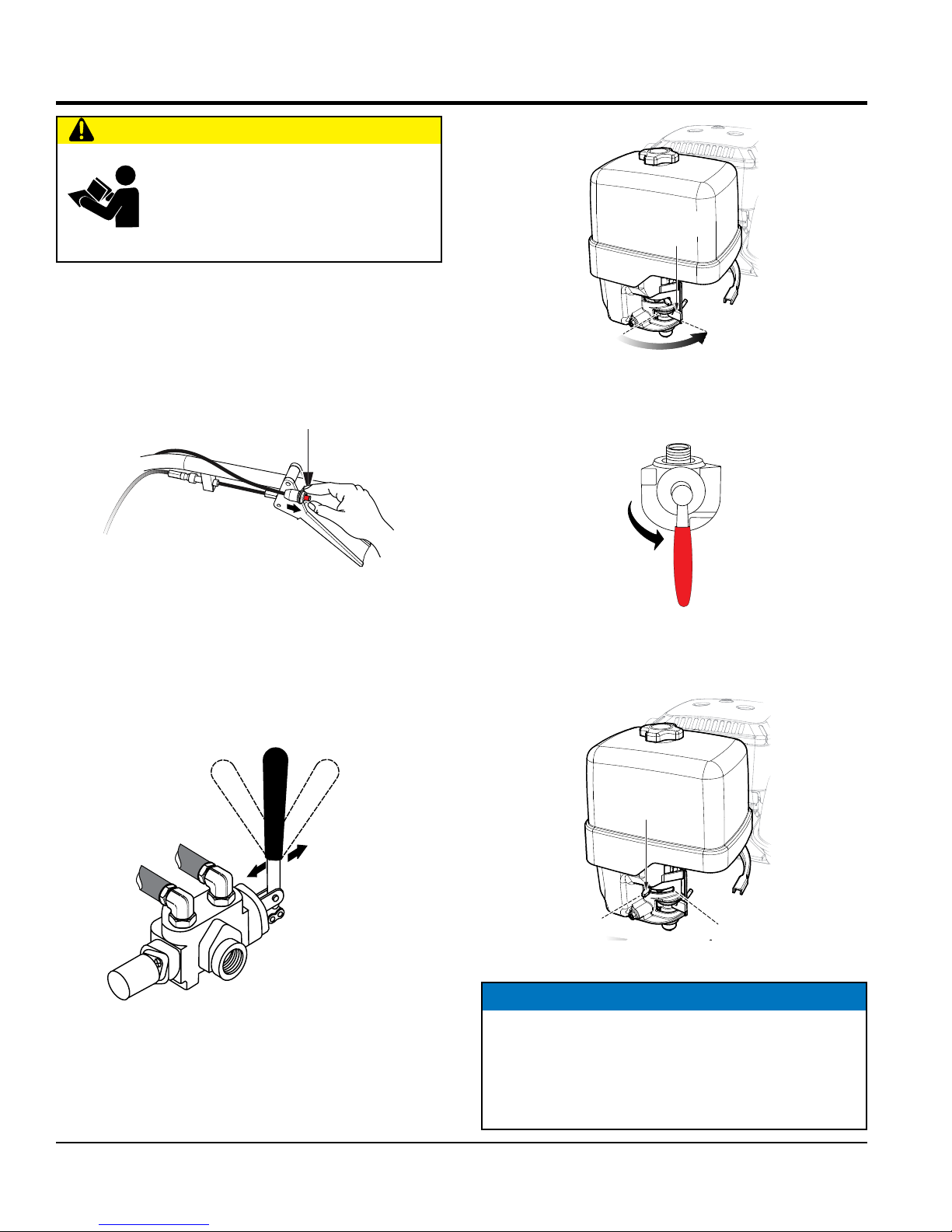
OPERATION
FUEL VALVE
LEVER
1. Before attempting to start the power buggy, make sure
that the safety kill switch (Figure 10) is not pushed
in. The power buggy will not start with the kill switch
engaged.
Figure 10. Kill Switch OFF
KILL SWITCH
(PULL)
2. Place the travel control lever (Figure 11) in the
NEUTRAL position.
OFF
ON
Figure 12. Engine Fuel Lever (ON)
4. Place the fuel tank ON/OFF valve (Figure 13) in the ON
position.
OFF
Figure 13. Fuel Tank ON/OFF Valve (ON)
FUEL
ON
5. If starting a cold engine, place the choke lever
(Figure 14) in the CLOSED position.
Figure 11. Travel Control Lever
3. Place the engine fuel lever to the ON position.
(Figure 12).
PAGE 22 — WBH-16EF CE POWER BUGGY • OPERATION AND PARTS MANUAL — REV. #0 (09/19/18)
CHOKE
LEVER
CLOSE
Figure 14. Engine Choke Lever (Closed)
NOTICE
The CLOSED position of the choke lever enriches
the fuel mixture for starting a cold engine. The OPEN
position provides the correct fuel mixture for normal
operation after starting, and for restarting a warm
engine.
OPERATION
W
6. If starting a warm engine or the temperature is warm,
place the choke lever (Figure 15) in the OPEN position.
CHOKE
LEVER
CLOSE
OPEN
Figure 15. Engine Choke Lever (Open)
7. Move the throttle lever halfway between the FAST and
SLOW position (Figure 16) for starting.
8. Place the ignition key (Figure 17 ) in the START position
and hold it until the engine starts. When the engine
starts, release the key, allowing it to return back to the
ON position.
S
T
A
R
T
Figure 17. Engine ON/OFF Switch
(Electric Start Models)
9. Make sure the choke lever has been placed in the
OPEN position (Figure 15) before operating the power
buggy.
10. Place the throttle lever in the FAST position
THROTTLE
LEVER
FAST
SLO
Figure 16. Throttle Lever
11. Before the buggy is placed into operation, run the
engine for several minutes. Check for fuel leaks, and
noises that would associate with a loose guard or cove.
WBH-16EF CE POWER BUGGY • OPERATION AND PARTS MANUAL — REV. #0 (09/19/18) — PAGE 23
PARKING BRAKE LEVER SET
OPERATION
PRE-CHECK
1. Engage the parking brake lever (Figure 18) and attempt
to rock the buggy back and forth. If the wheels turn
during the rocking motion, adjust the brakes as outlined
in the maintenance section of this manual.
PARKING BRAKE LEVER RELEASED
Figure 18. Parking Brake Lever
2. Place the engine's throttle lever (Figure 16) in the slow
(idle) position.
PARKING BRAKE/DIRECTION LEVER
Before the power buggy can be put into operational use,
it is best to perform a test run to make certain that all
components are functioning properly.
1. Place the buggy on flat solid ground.
2. Engage the parking brake lever.
3. Place the engine's throttle control (Figure 16) in the
SLOW (idle) position.
4. Place the power buggy's direction lever (Figure 20) in
the forward direction.
FORWARD
NEUTRAL
REVERSE
TRAVEL
CONTROL
LEVER
3. Check the speed control lever (Figure 19) located on
the right side of the handle bar. The speed control
should work freely when squeezed by hand, and return
to the neutral position when released.
SPEED CONTROL
LEVER
Figure 19. Speed Control Lever
Figure 20. Direction Lever
5. Slowly squeeze the speed control lever slightly
(Figure 19), for a short period of time to test the brake
holding capacity. If the buggy moves forward, adjust
the brakes as outlined in the maintenance section of
this manual.
6. If the buggy does not move forward, release the
speed control, and disengage the parking brake. If
the buggy creeps forward or reverse while the parking
brake is disengaged, the machine will require service
adjustment of the pump control lever as outlined in the
maintenance section of this manual.
PAGE 24 — WBH-16EF CE POWER BUGGY • OPERATION AND PARTS MANUAL — REV. #0 (09/19/18)
OPERATION
TRAVELING
1. With the engine running and parking brake released,
place the direction lever (Figure 20) in the forward
direction.
2. Squeeze the speed control lever (Figure 19) slightly
until the buggy begins to move in a forward direction.
Initially, let the buggy travel at about 3 MPH.
3. When using the buggy for the first time, test the brake.
With the right foot, step up and place it on the brake
pedal (Figure 21). Gradually apply pressure to the
brake pedal until the buggy comes to rest.
WBH16
STEERING
To steer the buggy, use the handle bar in front of the
operator platform.
1. To turn left when traveling in the forward direction, turn
the handle bar clockwise (Figure 22).
TURN HANDLE BAR
CLOCKWISE TO STEER
BUGGY TO THE LEFT
TURN HANDLE BAR
COUNTERCLOCKWISE TO STEER
BUGGY TO THE LEFT
WBH16EF
Figure 22. Steering the Buggy
BRAKE PEDAL
Figure 21. Brake Pedal
4. Test the brake at different speeds until you are
comfortable with stopping the buggy. If the brakes
do not seem to stop the buggy adequately, refer to
the maintenance section of this manual for brake
adjustment instructions.
5. When starting and stopping is confirmed to be
functioning properly, the buggy is ready for operation.
2. To turn right when traveling in the forward direction,
turn the handle bar in the counterclockwise direction.
CAUTION
DO NOT steer the buggy left or right when traveling up
or down on a grade. Travel in a straight path.
CAUTION
Avoid sudden and quick turns. When steering, turn
the handle bar slowly. Always face the controls when
traveling.
WBH-16EF CE POWER BUGGY • OPERATION AND PARTS MANUAL — REV. #0 (09/19/18) — PAGE 25
 Loading...