

Page 1

PARTS AND OPERATION MANUAL
VR- 36HA
VIBRATORY ROLLER
© COPYRIGHT 2000, MULTIQUIP INC.
Revision #6 (06/13/06)
MULTIQUIP INC
18910 WILMINGTON AVE. 800-427-1244
CARSON, CALIFORNIA 90746 FAX: 800-672-7877
310-537-3700
800-421-1244 800-478-1244
FAX: 310-537-3927 FAX: 310-631-5032
E-mail:mq@multiquip.com • www:multiquip.com
Atlanta • Boise • Dallas • Houston • Newark
Montreal, Canada • Manchester, UK
Rio De Janiero, Brazil • Guadalajara, Mexico
..
. PARTS DEPARTMENT:
..
SERVICE DEPARTMENT/TECHNICAL ASSISTANCE:
Page 2
Page 3

HERE'S HOW TO GET HELP
PLEASE HAVE THE MODEL AND SERIAL NUMBER
ON-HAND WHEN CALLING
PARTS DEPARTMENT
800-427-1244 or 310-537-3700
FAX: 800-672-7877 or 310-637-3284
SERVICE DEPARTMENT/TECHNICAL ASSISTANCE
800-478-1244 or 310-537-3700
FAX: 310- 537-4259
WARRANTY DEPARTMENT
888-661-4279, or 310-661-4279
FAX: 310- 537-1173
MAIN
800-421-1244 or 310-537-3700
FAX: 310-537-3927
VR-36HA - VIBRATORY ROLLER — PARTS & OPERATION MANUAL — REV. 6 (06/13/06) — PAGE 3
Page 4

TABLE OF CONTENTS
Here's How To Get Help .......................................... 2
Table Of Contents ................................................... 3
Parts Ordering Procedures ..................................... 4
Rules For Safe Operation ................................... 5-6
Operations .......................................................... 7-8
MULTIQUIP — VR36HA
VIBRATORY ROLLER
Explanation Of Codes In Remarks Column .......... 10
Suggested Spare Parts ......................................... 11
Engine Cover & Articulated Joint ..................... 12-13
Hydraulic Oil Filters .......................................... 14-15
Engine Coupler ................................................ 16-17
Hydraulic Drive Pumps..................................... 18-19
Hydraulic fitting & Exhaust Systems ................ 20-21
Adapters, Steel Lines & Hoses ........................ 22-23
Adapters, Steel Lines & Hoses ........................ 24-25
Front Drum & Exciter........................................ 26-27
Rear Drum ....................................................... 28-29
Sheet Metal, Fuel & Water Tanks & Seat ......... 30-31
Steering Cylinder, Rear Frame Components &
Throttle Control ................................................ 32-33
Steering Column & Switches ............................ 34-35
Scrapers ........................................................... 36-37
Battery, Rear Water Pipes ................................ 38-39
Transmission & Brake Control.......................... 40-41
Brake Control Compnents ............................... 42-43
Water System ................................................... 44-45
Hydraulic Manifold ........................................... 46-47
Hoses & Electrical System ............................... 48-49
Drive Motor, Tubes, Hoses, Fuel Pump ........... 50-51
SERVICE INFORMATION
Maintenance (1.0) ................................................. 52
Engine Lubrication (1.1)........................................ 52
Center Joint (articulation) (1.2) ............................. 52
Rear Drum (1.3) .................................................... 52
Vibrator Oil (1.4) ................................................... 52
Hydraulic System (1.5).......................................... 53
Changing Hydraulic Oil & Filters (1.6) .................. 53
Scraper Bars & Cocoa Mats (1.7) ......................... 53
Towing Valve (1.8) ................................................. 53
Hydraulic System (2.0).......................................... 53
General — Hydraulic Flow Diagram (2.1) ............. 53
Drum Drives (2.2) ................................................. 54
Vibration & Streering (2.3) .................................... 54
Back Pressure Valve (2.4) ..................................... 54
Towing Valve (2.5) ................................................. 54
Testing Hydraulic Pressure (2.6)........................... 54
Hydraulic Diagram ................................................ 55
A. Drive Circuit Pressure ....................................... 56
B. Adjusting Drive Relief Valves............................. 57
C. Vibration Circuit Pressure ................................. 57
D. Steering Circuit Pressure .................................. 57
Removing & Replacing Hydraulic
Pump Assembly (2.7)............................................ 57
Removing & Replacing Vibration/Steering Pumps &
Hydraulic Schematic (2.8) ..................................... 58
Drum & Main Frame (3.0) ..................................... 59
Removing Front Drum (3.1) .................................. 59
Front Drum Disassembly (3.2) .............................. 59
Front Drum Assembly (3.3)................................... 59
Vibrator Assembly Removal (3.4) ......................... 60
Vibrator Assembly Installation (3.5) ...................... 60
Vibrator Disassembly (3.6) ................................... 60
Vibrator Assembly (3.7) ........................................ 60
Installation Front Drum (3.8) ................................. 61
Drive Motor Removal (3.9) ................................... 61
Drive Motor Installation (3.10) .............................. 61
Rear Drum Removal (3.11) .................................. 61
Rear Drum Installation (3.12) ............................... 62
Alternator/Regulator (4.0) ..................................... 62
Neutral Safety Switch (4.1) ................................... 62
Vibration Solenoid (4.2) ........................................ 62
Ignition Switch (4.3) .............................................. 63
Starter Solenoid (4.4) ........................................... 63
Fuses (4.5) ............................................................ 63
Electrical Schematic (4.6) ..................................... 63
Terms and Conditions Of Sale — Parts ................ 64
NOTE: Specification and part number
are subject to change without notice.
PAGE 4 — VR-36HA • VIBRATORY ROLLER — PARTS & OPERATION MANUAL — REV. 6 (06/13/06)
Page 5
PARTS ORDERING PROCEDURES
■■
■ Dealer account number
■■
■■
■ Dealer name and address
■■
■■
■ Shipping address (if different than billing address)
■■
■■
■ Return fax number
■■
■■
■ Applicable model number
■■
■■
■ Quantity, part number and description of each part
■■
■■
■ Specify preferred method of shipment:
■■
UPS Ground
•
UPS Second Day or Third Day*
•
UPS Next Day*
•
Federal Express Priority One (please provide us with your Federal
•
Express account number)*
Airborne Express*
•
Truck or parcel post
•
*Normally shipped the same day the order is received, if prior to 2PM west coast time.
Earn Extra Discounts when
you order by FAX!
All parts orders which include complete part numbers
and are received by fax qualify for the following extra
discounts:
Number of
line items ordered Additional Discount
1-9 items 3%
10+ items** 5%
Get special freight allowances
when you order 10 or more
line items via FAX!**
■■
■
UPS Ground Service at no charge for freight
■■
■■
■
PS Third Day Service at one-half of actual freight cost
■■
No other allowances on freight shipped by any other carrier.
**Common nuts, bolts and washers (all items under $1.00 list price)
do not count towards the 10+ line items.
Extra Fax DiscountExtra Fax Discount
Extra Fax Discount
Extra Fax DiscountExtra Fax Discount
for Domestic USAfor Domestic USA
for Domestic USA
for Domestic USAfor Domestic USA
Dealers OnlyDealers Only
Dealers Only
Dealers OnlyDealers Only
Now! Direct TOLL-FREE access
to our Parts Department!
Toll-free nationwide:
800-421-1244
Toll-free FAX:
*DISCOUNTS ARE SUBJECT TO CHANGE*
Fax order discount and UPS special programs revised June 1, 1995
VR-36HA • VIBRATORY ROLLER — PARTS & OPERATION MANUAL — REV. 6 (06/13/06) — PAGE 5
800/6-PARTS-7 • 800-672-7877
Page 6

RULES FOR SAFETY OPERATION
Read and understand this manual before attempting to operate
the machine.
The VR-36H roller has been designed for asphalt application
and compaction of granular soils used in site preparation. Use
the machine only for the purpose intended and by experienced
personnel who understand this operating manual and all safety
decals.
Keep this manual with the machine and refer to it frequently.
DANGER!
taken to prevent personal injury during
operation, inspection, maintenance and
service.
CAUTION!
operation and maintenance of this machine.
SAFETY RULES
■
■
■
Indicates when special observation is needed during
Completely familiarize yourself with the operation and safety
of this machine
DO NOT remove or modify any parts of the machine. Doing
so may result in the warranty becoming invalid.
DO NOT use the machine for any purpose other than that
which it is intended.
BEFORE USE.
Indicates extreme care should be
■
Whenever possible, always stop the unit on a stable, level
and hard surface. If the machine must be stopped on an
incline; before leaving the operator’s seat, secure the
parking brake and stop the engine; then chock both the
front and rear drums securely. Always remove the
ignition key to prevent unauthorized personnel from
operating the machine.
■
If malfunction occurs in the travel lever mechanism, speed
and direction will be impossible to control. Immediately stop
the
■
In the event of hydraulic hose or pipe failure, promptly return
the travel lever to the “neutral” position, stop the engine
and set the parking brake.
■
If the steering system operates improperly, immediately stop
the engine and apply the parking brake.
■
When malfunctions occur, always remove the ignition key
and place a “DO NOT OPERATE” sign in the operator’s
seat.
DANGER!
dangerous and cause death. Operate the
machine only in well ventilated areas.
Exhaust gasses are extremely
■
Always wear proper safety equipment:
hard hat
safety glasses
work clothes
safety shoes
protective gloves
respirator in dusty environments
DANGER!
machine. This is a pinch point. Never place
yourself or allow anyone else to stand near the
unit while the engine is running.
■
Start the unit only when seated in the operator’s position.
(see starting instructions)
Stay Clear of turning points of
INSPECTION PRIOR TO STARTING
DANGER!
machine parked on a stable, level and hard
surface. Never inspect the unit with the engine
running. Inspections should only be performed
by trained and qualified personnel.
CAUTION!
of the machine and only with the engine STOPPED!
■
■
■
■
Perform the following checks before each operation
Check hydraulic oil, engine oil, and fuel levels and for
leakage.
Check all hydraulic components and fittings for wear.
Insure smooth movement of the travel lever, throttle and
parking brake.
Check all fasteners (bolts & nuts) for tightness.
Perform inspections only with the
PAGE 6 — VR-36HA • VIBRATORY ROLLER — PARTS & OPERATION MANUAL — REV. 6 (06/13/06)
Page 7

RULES FOR SAFETY OPERATION
STARTING THE ENGINE
DANGER!
clean and free from debris, dirt, oil, grease, mud,
asphalt or anything else that may become a
hazard to free movement of the operator.
■
Make sure no unauthorized personnel are near the machine
before attempting to start the unit.
DANGER!
from the operator’s position.
■
Always use seat belts when provided.
■
Adjust the seat to obtain the most comfortable position.
■
Place the travel lever in the “neutral” position
attempting to start the unit.
■
Make sure that the “vibrator” switch is in the “OFF” position.
■
Pull the “choke” knob to full choke (see engine operating
manual).
Always keep the operator’s area
Start and operate the unit only
BEFORE
INSPECTION (After Start-Up)
■
Run the engine at an idle 3 to 5 minutes. In colder climates,
longer warm periods may be necessary. Sufficiently
warming the engine allows all lubricants to reach the proper
operating temperature.
CAUTION!
is running.
Test the steering for proper operation - left to right.
■
■
Do not leave the operator’s position while the engine
DANGER!
steering function if anyone is near the unit
or in the way of the front or rear drums.
While seated in the operator’s seat and with the engine
running, check that the hydraulic oil level indicator registers
in the “operation” zone.
Check for abnormal noise, odor, exhaust color or other
sign that may be out of the ordinary.
Do not attempt to check the
■
Turn the key to the start position to the right of the “ON”
position. (The ignition switch is spring loaded to prevent
the starter from being constantly engaged.)
■
As soon as the engine has started, release the ignition key.
■
Adjust the choke as required until the engine runs smoothly.
CAUTION!
running.
Do not operate the starter switch when the engine
ROPS — Roll Over Protection System
It is strongly suggested that ROPS and seat
belts be installed on this machine to protect the
operator against the unlikely event of a rollover.
The ROPS are sold as a optional accessory item and may be
ordered by calling:
Multiquip Sales • 800-421-1244 - P/N VR36ROPS
The following is a few examples of hazardous conditions of
when ROPS must be used:
1) When working on slopes or near open trenches
2) Hollow spaces or rocks that might be below the surface.
3) Sharp steering movements.
4) Surfaces that may be slippery or objects in the roller path.
VR-36HA • VIBRATORY ROLLER — PARTS & OPERATION MANUAL — REV. 6 (06/13/06) — PAGE 7
Page 8

VR-36HA — OPERATIONS
OPERATION
By moving the travel lever forward or backward, the machine will
travel in either forward or reverse. The speed in which movement
of this lever is made is directly related to the amount of pressure
that is applied to the travel lever in each direction. Travel speed
is infinitely variable from 0 to 4.8 mph.
DANGER!
and obstacles are free from the roller’s path. Serious injury or
death can result!
CAUTION!
changing the direction of travel. Changing directions before the
roller comes to a complete stop will result in excessive force
being applied to the transmission and drive system which will
reduce overall service life.
COMPACTION
In order to apply vibration to the surface, the vibrator switch must
be in the “ON” position. If the vibration appears to be weak or
slow, allow the machine to warm-up thoroughly, and check the
hydraulic oil level. Add hydraulic oil if necessary.
Before operating the roller, make sure that personnel
Allow the roller to come to a complete stop before
PARKING BRAKE
CAUTION!
stopped. Do not operate the machine with the parking brake in
the “SET” position. Severe brake wear can result.
ENGINE SHUT-DOWN
DANGER!
running.
CAUTION!
or grade, stop the engine, set the parking brake and place chocks
in the front and rear of each drum.
■
Place the travel lever in the “neutral” position.
■
Return the throttle lever to the idle position.
■
Turn the vibration switch to the “OFF” position.
■
Set the parking brake
■
Allow the engine to idle for 3 to 5 minutes prior to stopping
to allow proper cool-down period.
■
Stop the engine and remove the ignition key.
Always apply the parking brake when the roller is
Do not leave the operator’s seat while the engine is
Should stopping the unit be unavoidable on a slope
CAUTION!
or other hard surface while the vibrator is “ON”.
Do not allow the roller to operate on cured concrete
LOADING AND TRANSPORTING
DANGER!
WATER SYSTEM
The built-in water sprinkling system is designed to apply sufficient
quantities of water to the surface of the rollers. This method
prevents fresh asphalt from sticking to the drums while the rolling
operation is taking place.
The water system is fully adjustable from the operator’s position
by adjusting the two water valves. The front valve controls the
water supply to the front drum, and the rear valve controls water
to the rear drum.
Each roller is equipped with drum scrapers that are lined with
cocoa mats. These mats must be wetted before operation either
by the water supply system or other water source.
REFUELING
DANGER!
Spilled gasoline can cause fire or explosion and can cause
serious injury or even death! Do not smoke or allow sparks or
open flame near the machine at any time - especially when
refueling. Clean the engine of any spilled fuel BEFORE restarting.
Do not attempt to refuel the engine while running!
LEVEL, HARD GROUND OR PAVEMENT. Serious injury or
death can result from improper loading, lifting or unloading. Use
caution!
■
When driving the roller onto a transporting vehicle or trailer
■
Use ramps or other suitable material of sufficient strength
to support the roller.
■
Remove mud, oil, ice, snow or any other slippery materials
from the ramps and bed of the vehicle to avoid accidents.
■
After loading, apply the parking brake, lock the frame with
the locking bar that is provided.
■
Use chain and binders or other suitable means to firmly
secure the load before attempting to move the vehicle.
■
Lifting the roller onto a transporting vehicle or trailer
■
Only use the lifting points for the roller that are clearly
marked as “lifting point”.
DANGER!
machine. Serious injury or death may result.
ALWAYS LOAD AND UNLOAD THE ROLLER ON
Do not allow personnel under or near any suspended
PAGE 8 — VR-36HA • VIBRATORY ROLLER — PARTS & OPERATION MANUAL — REV. 6 (06/13/06)
Page 9

■
Remove mud, oil, ice, snow or any other slippery materials
from the ramps and bed of the vehicle to avoid accidents.
■
After loading, apply the parking brake, lock the frame with
the locking bar that is provided.
■
Use chain and binders or other suitable means to firmly
secure the load before attempting to move the vehicle.
VR-36HA — OPERATIONS
SERVICE AND INSPECTION
Performing all periodic inspections and service work on a timely
basis will result in increased performance, productivity and
reduced maintenance costs.
When the roller is used in severe, unusually dusty or dirty, or
extremely humid or hot environments, it will be necessary to
perform routine service and inspections more frequently.
BATTERY INFORMATION
DANGER!
damage eyes, skin and clothing upon contact. Always wear proper
safety eye protection, rubber gloves and other safety clothing.
Should acid contact the eyes, flush immediately with clean water
and get prompt medical attention. If acid comes in contact with
skin, wash immediately with clean water and get prompt medical
attention.
DANGER!
are extremely flammable and explosion can result.
■
■
■
■
■
■
Lead acid batteries contain sulfuric acid which will
Avoid fire and open flame near batteries. Battery acids
Clean and inspect battery terminals regularly.
Non-use of machine will result in reduced battery charge
level and will damage the plates which reduces the battery
life.
Keep battery caps tightly fastened at all times.
Add distilled water as needed
Proper sequence must be observed during installation and
removal of batteries:
Removal - Disconnect the negative (ground) terminal first,
then the positive terminal.
DANGER!
Exhaust gasses are dangerous and cause injury or death. Never
operate this or any other machine within an enclosed space.
SERVICE INSTRUCTIONS CHART
Engine Speed 3500 RPM
Exciter Speed 3900 VPM
Exciter Lubrication Type SAE 30
Grease Type Alvania #2 or equiv.
Hydraulic Oil Type ISO46 (Anti-Wear)
Hydraulic Filter Change every 500 hours
Always operate the machine in a well ventilated area.
16 oz. (475 ml)
Every 1100 hours
Articulated joint (4 fittings)
Static drum bearing (1 fitting)
Every 75 hours
5.7 gallons (21.6 liters)
Every 1100 hours
■
Installation - Install the Positive terminal first, then the
negative (ground) terminal.
DANGER!
in contact with each other. Serious injury could result.
Never allow the negative and positive cables to come
VR-36HA • VIBRATORY ROLLER — PARTS & OPERATION MANUAL — REV. 6 (06/13/06) — PAGE 9
Engine Lubrication/ Refer to Engine Owners Manual
Service
CAUTION!
will result in extreme damage to the unit’s hydraulic system.
Running the machine without sufficient hydraulic oil
Page 10

VR-36HA — EXPLANATION OF CODE IN REMARKS COLUMN
How to read the marks and remarks used in this parts book.
Section 1: Items Found In the “Remarks” Column
Serial Numbers-Where indicated, this indicates a serial
number range (inclusive) where a particular part is used.
Model Number-Where indicated, this shows that the
corresponding part is utilized only with this specific model
number or model number variant.
Section 2: Items Found In the “Remarks” Column
Serial Numbers-Where indicated, this indicates a serial number
range (inclusive) where a particular part is used.
Model Number-Where indicated, this shows that the
corresponding part is utilized only with this specific model number
or model number variant.
Section 3: Items Found In the “Items Number” Column
All parts with same symbol in the number column,
■
, belong to the same assembly or kit.
Note: If more than one of the same reference number is listed,
the last one listed indicates newest (or latest) part available.
If more than one of the same reference number is
listed, the last one listed indicates newest (or latest)
part available.
, #, +, %, or
*
NOTE
NOTE
The contents of this catalog are
subject to change without notice
.
PAGE 10 — VR-36HA • VIBRATORY ROLLER — PARTS & OPERATION MANUAL — REV. 6 (06/13/06)
Page 11

VR36HA
1 Unit
Qty. . P/N ................... Description
2 ..... 508667 ............. HYDRAULIC FILTER CART.
3 ..... 506141 ............. RUBBER SHOCK MOUNTS
6 ..... 508433 ............. RUBBER SHOCK MOUNTS
1 ..... 506097 ............. FWD./REV. CABLE
1 ..... 510229 ............. ENG THROTTLE CABLE
1 ..... 506239 ............. ENGINE CHOKE CABLE
2 ..... 503735 ............. FLANGE BEARING
4 ..... 352431090 ....... INLINE FUEL FILTER
1 ..... 9807956846 ..... SPARK PLUG
1 ..... 17010ZJ1000 ... ELEMENT SET
1 ..... 506267K........... KEY
VR-36HA — SUGGESTED SPARE PARTS
NOTE
Part numbers on this Suggested
Spare Parts List may supercede/
replace the P/N shown in the text
pages of this book.
VR-36HA • VIBRATORY ROLLER — PARTS & OPERATION MANUAL — REV. 6 (06/13/06) — PAGE 11
Page 12

VR-36HA — ENGINE COVER & ARTICULATED JOINT
30
31
PAGE 12 — VR-36HA • VIBRATORY ROLLER — PARTS & OPERATION MANUAL — REV. 6 (06/13/06)
Page 13

VR-36HA — ENGINE COVER & ARTICULATED JOINT
MODEL VR-36H
ENGINE COVER & ARTICULATED JOINT
NO PART NO PART NAME QTY. SERIAL NO.
1 506100 COVER ........................................................................ 1 ........................... S/N 960601 TO 970630
1 510074 COVER ........................................................................ 1 ........................... S/N 970701 & UP
2 506103 ARTICULATED SHAFT 1
3 506095 CABLE 1
4 506101 FRONT COVER 1
5 504544 LATCH ASSEMBLY 2
7 491687 KING PIN 2
9 506158 HEX. HEAD SCREWS 5/16" NC x ¾" G5 7
10 490937 RUBBER BUMPER 2
11 492582 LOCK NUT 5/16" NC 2
12 492597 FLAT WASHER 5/16" 2
13 506176 FLAT HEAD SOCKET S. 5/16 NC x 1" G5 2
14 506102 ARTICULATED BODY 1
15 506164 BEARING 1
16 506165 BEARING 3
17 506104 RETAINER 1
18 492269 SOCKET HEAD SCREW 5/16" NF x ¾" G5 3
19 506105 PIVOT 1
20 506172 HEX. HEAD SCREW ½" NC x 1, 3/8" G5 4
21 506124 BUSHING 2
22 506107 PILLOW BLOCK 2
23 491705 GREASE FITTING ¼" NF 4
24 506109 FLAT WASHER 4
25 503982 HEX. HEAD SCREW 5/8" NC x 2" G5 4
26 506160 SHAFT SEAL 2
27 506110 PLUG 2
28 506166 SHIM 3
29 506110 DUST CAP 2
30 510292 ACCESS COVER ......................................................... 1 ........................... S/N 970701 & UP
31 506176 BOLTS ......................................................................... 4 ........................... S/N 970701 & UP
WHEN ORDERING PARTS, ALWAYS GIVE MODEL NUMBER AND SERIAL NUMBER OF UNIT.
VR-36HA • VIBRATORY ROLLER — PARTS & OPERATION MANUAL — REV. 6 (06/13/06) — PAGE 13
Page 14
VR-36HA — HYDRAULIC OIL FILTERS
51
PAGE 14 — VR-36HA • VIBRATORY ROLLER — PARTS & OPERATION MANUAL — REV. 6 (06/13/06)
Page 15

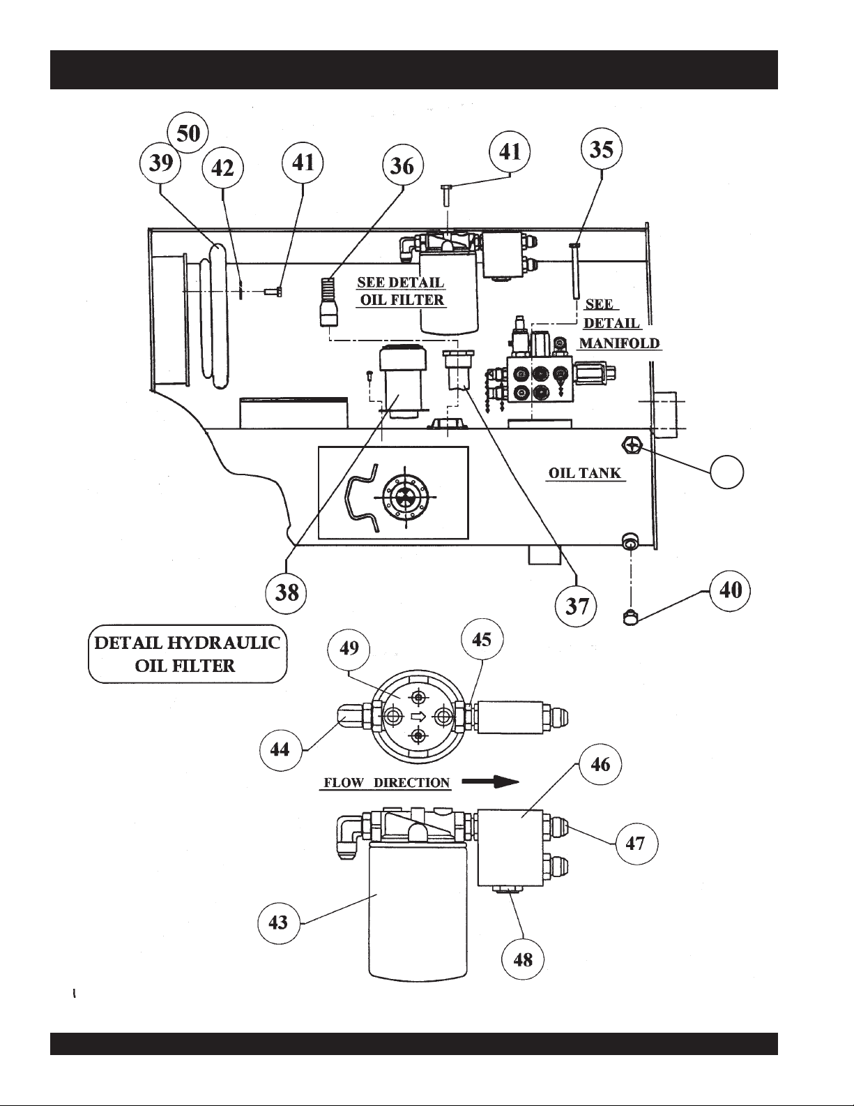
VR-36HA — HYDRAULIC OIL FILTERS
MODEL VR-36H
HYDRAULIC OIL FILTER
NO PART NO PART NAME QTY. SERIAL NO.
35 508814 HEX. HEAD SCREW 5/16" NC x 3, ¼" G5 2
36 506218 FITTING INLET 1
37 506221 SUCTION FILTER 1
38 507278 CAP 1
39 508287 SEAL - AIR INTAKE 1
40 506205 PLUG W/O-RING 1
41 492356 HEX. HEAD SCREW ¼" NC x ¾" G5 5
42 492622 LOCK WASHER 3
43 508667 OIL FILTER, HYDRAULIC 1
44 506199 FITTING ELBOW 1
45 506204 FITTING 1
46 506244 MANIFOLD BLOCK 1
47 506193 ADAPTER 2
48 508670 CHECK VALVE 1
49 508664 FILTER ADAPTOR 1
50 508287 SEAL INSIDE BODY 1
51 490181 SIGHT GLASS 1
WHEN ORDERING PARTS, ALWAYS GIVE MODEL NUMBER AND SERIAL NUMBER OF UNIT.
VR-36HA • VIBRATORY ROLLER — PARTS & OPERATION MANUAL — REV. 6 (06/13/06) — PAGE 15
Page 16
NOTE: ENGINE FUEL
PUMP, REF. TO PAGE 48
VR-36HA — ENGINE COUPLER
PAGE 12
PAGE 16
PAGE 16 — VR-36HA • VIBRATORY ROLLER — PARTS & OPERATION MANUAL — REV. 6 (06/13/06)
Page 17

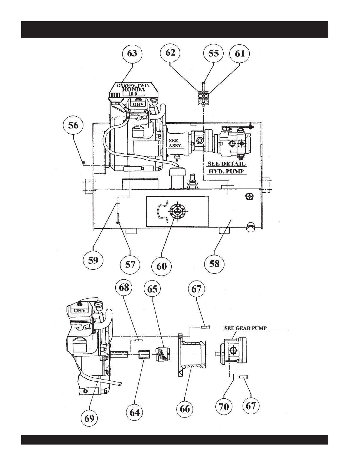
VR-36HA — ENGINE COUPLER
MODEL VR-36H
ENGINE COUPLER
NO PART NO PART NAME QTY. SERIAL NO.
55 492371 HEX. HEAD SCREW 5/16" NC x 3" G5 1
56 492583 LOCK NUT 3/8" NC 4
57 492379 HEX. HEAD SCREW 3/8" NC x 2" G5 4
58 505891 FRONT FRAME 1
59 492598 FLAT WASHER 8
60 506159 SOCKET HEAD SCREWS ½" NC x 1-3/8" G 8
61 505976 HOSE RETAINER 2
62 506185 SUPPORT PLATE 1
63 508350 ENGINE HONDA 18 HP. GX610 QZB 1
64 506234 SPACER 1
65 506235 COUPLING 1
66 506236 ADAPTER 1
67 492376 HEX. HEAD SCREW 3/8" NC x 1-1/4" G5 6
68 500569 SQUARE KEY ¼" x 1 ¼" 1
69 506240 FUEL HOSE 3
70 508346 LOCK WASHER SPECIAL 2
WHEN ORDERING PARTS, ALWAYS GIVE MODEL NUMBER AND SERIAL NUMBER OF UNIT.
VR-36HA • VIBRATORY ROLLER — PARTS & OPERATION MANUAL — REV. 6 (06/13/06) — PAGE 17
Page 18
VR-36HA — HYDRAULIC DRIVE PUMPS
PAGE 18 — VR-36HA • VIBRATORY ROLLER — PARTS & OPERATION MANUAL — REV. 6 (06/13/06)
Page 19

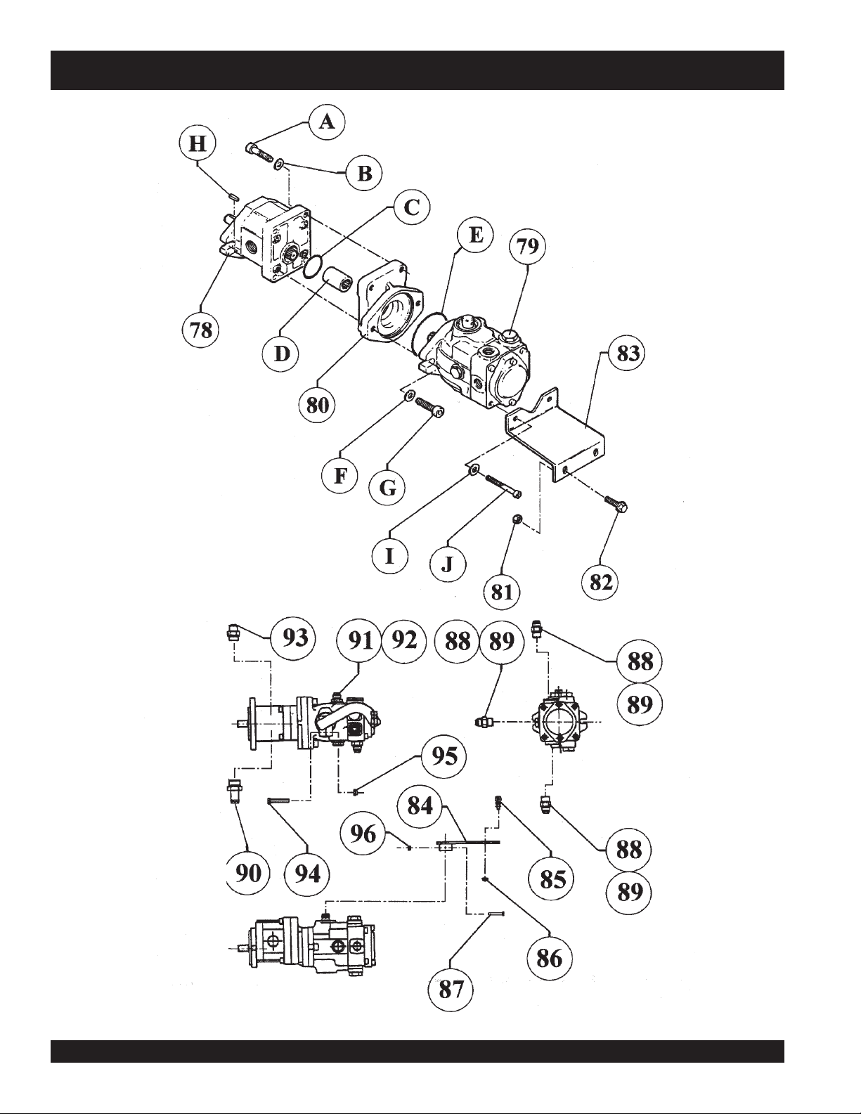
VR-36HA — HYDRAULIC DRIVE PUMPS
MODEL VR-36H
HYDRAULIC DRIVE PUMPS
NO PART NO PART NAME QTY. SERIAL NO.
78 507845 GEAR PUMP (INCL. A, B, C, D, E, F, G, H.) 1
79 506187 PISTON PUMP (INCL. I, J.) 1
80 507860 FLANGE SUNDSTRAND 1
81 492582 LOCK NUT 5/16" NC 2
82 506158 HEX. HEAD SCREW 5/16" NC x ¾" G5 2
83 506225 PUMP SUPPORT 1
84 506243 LEVER – FORWARD/REVERSE 1
85 506098 BALL JOINT 1
86 508451 LOCK NUT ¼" – 28 NF 1
87 506227 HEX. HEAD SCREW 3/16" 24 NS x 1 ½" 1
88 508343 FITTING 3
89 508427 FLAT WASHER 21/30 (COPPER) 3
90 506217 FITTING 1
91 506219 FITTING 1
92 508428 FLAT WASHER SPECIAL (COPPER) 1
93 506203 FITTING 1
94 492367 HEX. HEAD SCREW 5/16" NC x 1 ¾" G5 1
95 492582 LOCK NUT 5/16" NC 1
96 503119 LOCK NUT 3/16" 24 NS 1
WHEN ORDERING PARTS, ALWAYS GIVE MODEL NUMBER AND SERIAL NUMBER OF UNIT.
VR-36HA • VIBRATORY ROLLER — PARTS & OPERATION MANUAL — REV. 6 (06/13/06) — PAGE 19
Page 20
VR-36HA — HYDRAULIC FITTING & EXHAUST SYSTEMS
PAGE 20 — VR-36HA • VIBRATORY ROLLER — PARTS & OPERATION MANUAL — REV. 6 (06/13/06)
Page 21

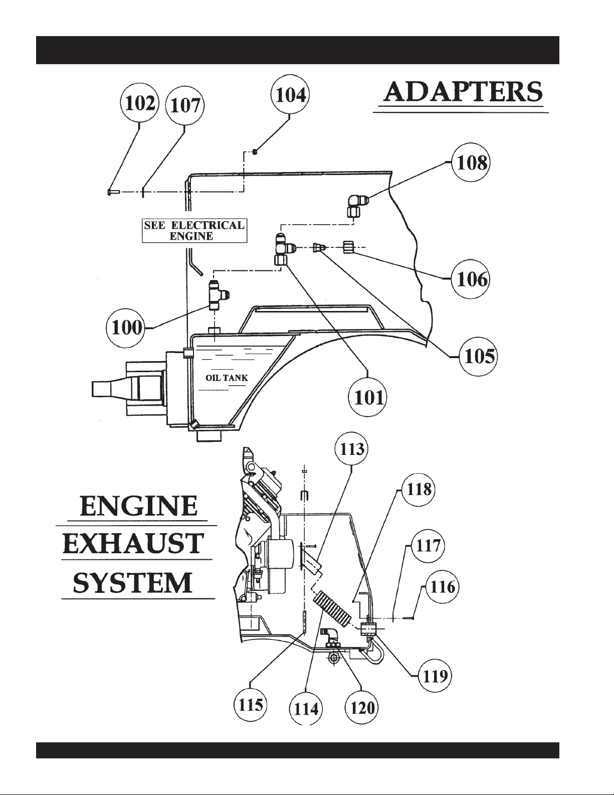
VR-36HA — HYDRAULIC FITTING & EXHAUST SYSTEMS
MODEL VR-36H
HYDRAULIC FITTING & EXHAUST SYSTEMS
NO PART NO PART NAME QTY. SERIAL NO.
100 506201 TEE 1
101 506202 ELBOW 1
102 492356 HEX. HEAD SCREW ¼" NC x ¾" G5 2
104 492581 LOCK NUT ¼" NC 2
105 506206 REDUCER 1
106 508472 NUT 06B-08 1
107 492596 FLAT WASHER ¼" 2
108 506195 ELBOW 1
113 506254 MOUNT – EXHAUST PIPE 1
114 506258 EXHAUST PIPE 1
115 506257 U-BOLT 2
116 492363 HEX. HEAD SCREW 5/16" NC x ¾" G5 2
117 492597 FLAT WASHER 5/16" 2
118 492582 LOCK NUT 5/16" NC 2
119 508337 EXHAUST FLANGE 1
120 506071 ELBOW 1
WHEN ORDERING PARTS, ALWAYS GIVE MODEL NUMBER AND SERIAL NUMBER OF UNIT.
VR-36HA • VIBRATORY ROLLER — PARTS & OPERATION MANUAL — REV. 6 (06/13/06) — PAGE 21
Page 22

VR-36HA — ADAPTERS, STEEL LINES & HOSES
PAGE 22 — VR-36HA • VIBRATORY ROLLER — PARTS & OPERATION MANUAL — REV. 6 (06/13/06)
Page 23

VR-36HA — ADAPTERS, STEEL LINES & HOSES
MODEL VR-36H
ADAPTERS, STEEL LINES & HOSES
NO PART NO PART NAME QTY. SERIAL NO.
124 505967 STEEL LINE 1
125 505952 FITTING 4
126 505968 STEEL LINE 1
127 490181 SIGHT GLASS 1
128 505970 STEEL LINE 1
129 505953 FITTING 1
130 505971 TUBE 1
131 506194 ELBOW 1
132 492368 HEX. HEAD SCREW 5/16" NC x 2" G5 1
133 508620 TUBE RETAINER 2
134 505976 SET TUBE CLAMP 2
135 506185 SUPPORT PLATE 2
136 492582 LOCK NUT 5/16" NC 1
137 505969 STEEL LINE 1
138 506208 CLAMP 1
139 506189 ELBOW 2
140 505957 HOSE 2
141 505958 HOSE 1
142 505972 STEEL LINE 1
143 505973 STEEL LINE 1
WHEN ORDERING PARTS, ALWAYS GIVE MODEL NUMBER AND SERIAL NUMBER OF UNIT.
VR-36HA • VIBRATORY ROLLER — PARTS & OPERATION MANUAL — REV. 6 (06/13/06) — PAGE 23
Page 24

VR-36HA — ADAPTERS, STEEL LINES & HOSES
PAGE 24 — VR-36HA • VIBRATORY ROLLER — PARTS & OPERATION MANUAL — REV. 6 (06/13/06)
Page 25

VR-36HA — ADAPTERS, STEEL LINES & HOSES
MODEL VR-36H
ADAPTERS, STEEL LINES & HOSES
NO PART NO PART NAME QTY. SERIAL NO.
150 508229 WIRING HARNESS 1
151 505976 HOSE RETAINER 5
152 492582 LOCKNUT 5/16" NC 3
153 505952 FITTING 2
154 506238 PROTECTION 5
155 492371 HEX. HEAD SCREW 5/16" NC x 3" G5 3
156 506185 SUPPORT PLATE 5
157 505954 HOSE 2
158 505959 HOSE 2
159 505962 HOSE 1
WHEN ORDERING PARTS, ALWAYS GIVE MODEL NUMBER AND SERIAL NUMBER OF UNIT.
VR-36HA • VIBRATORY ROLLER — PARTS & OPERATION MANUAL — REV. 6 (06/13/06) — PAGE 25
Page 26

VR-36HA — FRONT DRUM & EXCITER
EXCITER ASSEMBLY
PAGE 26 — VR-36HA • VIBRATORY ROLLER — PARTS & OPERATION MANUAL — REV. 6 (06/13/06)
Page 27

VR-36HA — FRONT DRUM & EXCITER
MODEL VR-36H
FRONT DRUM & EXCITER
NO PART NO PART NAME QTY. SERIAL NO.
166 505985 SHOCK MOUNT 6
167 492375 HEX. HEAD SCREW 3/8" NC x 1" G5 6
168 508346 LOCK WASHER 12
169 506133 COVER 1
170 506134 RETAINING RING 1
171 506132 O – RING 1
172 506131 BEARING 2
173 506126 FRONT DRUM ................................................... 1 ............................. S/N 980601 TO 980630
173 510280 FRONT DRUM ................................................... 1 ............................. S/N 980701 & UP
174 506127 HOUSING ........................................................... 1 .............................S/N 980601 TO 980630
174 510191 HOUSING ........................................................... 1 .............................S/N 980701 & UP
175 506129 ECCENTRIC SHAFT.......................................... 1 .............................S/N 980601 TO 980630
175 510278 ECCENTRIC SHAFT.......................................... 1 ............................. S/N 980701 & UP
177 506205 PLUG 1
178 492467 SET SCREW 5/16" NC x 3/8" 2
179 492472 SET SCREW 3/8" NC x ¾" 2
180 506137 BEARING HOUSING 1
181 506144 SEAL 1
182 490964 RETAINING RING 1
183 506135 RETAINING RING 1
184 506864 LOCK NUT M10 6
WHEN ORDERING PARTS, ALWAYS GIVE MODEL NUMBER AND SERIAL NUMBER OF UNIT.
VR-36HA • VIBRATORY ROLLER — PARTS & OPERATION MANUAL — REV. 6 (06/13/06) — PAGE 27
Page 28

VR-36HA — REAR DRUM
PAGE 24
REFER TO PAGE 48
PAGE 28 — VR-36HA • VIBRATORY ROLLER — PARTS & OPERATION MANUAL — REV. 6 (06/13/06)
Page 29

VR-36HA — REAR DRUM
MODEL VR-36H
REAR DRUM
NO PART NO PART NAME QTY. SERIAL NO.
190 505989 SOCKET HEAD SCREW ½" NC x 1 ¼" 4
191 492375 HEX. HEAD SCREW 3/8" NC x 1" G5 6
192 508342 HEX. HEAD SCREW M8 x 25 6
193 506141 SHOCK MOUNT 3
194 506142 MOUNT, VIBRATION MOTOR 1
195 492362 HEX. HEAD SCREW 5/16" NC x 5/8" G5 4
196 506220 VIBRATION MOTOR 1
197 508340 STUD M8 x 40 6
198 492264 SOCKET HEAD SCREW 3/8" NC x 1" 6
199 506145 BEARING HOUSING 1
200 506136 RETAINING RING 1
201 508341 LOCK NUT M8 6
202 506147 BEARING 1
203 506250 KEY 1
204 508665 FLEX COUPLING 1
205 508181 SUPPORT 1
206 508192 TUBE GUARD 1
207 508346 LOCK WASHER 6
208 508171 FLANGE DRUM SUPPORT 1
209 505988 PLUG 1
210 492395 HEX. HEAD SCREW ½" NC x 1 ¾" G5 2
211 503735 FLANGE BEARING 1
212 492584 LOCK NUT ½" NC 2
213 505893 REAR DRUM ............................................................... 1 .................. S/N 960601 TO 980630
213 510279 REAR DRUM ............................................................... 1 .................. S/N 980701 & UP
214 492375 HEX. HEAD SCREW 3/8" NC x 1" G5 6
215 505989 SOCKET HEAD SCREW ½" NC x 1 ¼" 12
216 508346 LOCK WASHER 6
WHEN ORDERING PARTS, ALWAYS GIVE MODEL NUMBER AND SERIAL NUMBER OF UNIT.
VR-36HA • VIBRATORY ROLLER — PARTS & OPERATION MANUAL — REV. 6 (06/13/06) — PAGE 29
Page 30

245
VR-36HA — SHEET METAL, FUEL & WATER TANKS, SEAT
244
PAGE 30 — VR-36HA • VIBRATORY ROLLER — PARTS & OPERATION MANUAL — REV. 6 (06/13/06)
Page 31

VR-36HA — SHEET METAL, FUEL & WATER TANKS, SEAT
MODEL VR-36H
SHEET METAL FUEL, WATER TANK & SEAT
NO PART NO PART NAME QTY. SERIAL NO.
221 492583 LOCK NUT 3/8" NC 9
222 508186 FUEL TANK 1
223 168038 CAP 1
224 506158 HEX. GLANGE SCREW 5/16" NC x ¾" G8 1
225 492376 HEX. HEAD SCREW 3/8" NC x 1 ¼" G5 6
226 506239 CHOKE CABLE 1
227 507888 SEAT 1
228 508187 CAP, WATER 1
229 508184 WATER TANK 1
230 492582 LOCK NUT 5/16" NC 4
231 491212 PLUG 2
232 505890 SHIELD 1
233 506240 HOSE, FUEL 1
234 506208 CLAMP, FUEL 3
235 20426 ELBOW 5
236 506253 WASHER, SPECIAL 6
237 508674 HEX. FLANGE SCREW 5/16" NC x 1" G8 7
238 506111 FLOOR PLATE 1
239 506083 GUARD ........................................................................ 1 ....................... S/N 960601 TO 980630
239 510113 GUARD ........................................................................ 1 ....................... S/N 980701 & UP
241 20421 FUEL SHUT OFF VALVE ............................................. 1 ....................... S/N 960601 & UP
242 492363 HEX. HEAD SCREW 5/16" NC x ¾" G5 4
243 505992 HEX. FLANGE SCREW 3/8" NC x 1" G8 3
244 352431090 FUEL FILTER 1
245 VR36ROPS
INCLUDES SEAT BELTS P/N 34478
*
ROLL OVER PROTECTION 1
*
WHEN ORDERING PARTS, ALWAYS GIVE MODEL NUMBER AND SERIAL NUMBER OF UNIT.
VR-36HA • VIBRATORY ROLLER — PARTS & OPERATION MANUAL — REV. 6 (06/13/06) — PAGE 31
Page 32

VR-36HA — STEERING CYLINDER, REAR FRAME COMPONENTS & THROTTLE CONTROL
STEERING & REAR FRAME
PAGE 32 — VR-36HA • VIBRATORY ROLLER — PARTS & OPERATION MANUAL — REV. 6 (06/13/06)
Page 33

VR-36HA — STEERING CYLINDER, REAR FRAME COMPONENTS & THROTTLE CONTROL
MODEL VR-36H
STEERING CYLINDER, REAR FRAME COMPONENTS & THROTTLE CONTROL
NO PART NO PART NAME QTY. SERIAL NO.
250 492586 LOCK NUT 5/8" NC 1
251 506167 PLASTIC WASHER 2
252 506154 SAFETY LOCKOUT BAR 1
253 506109 WASHER 5/8" 1
254 503982 HEX. HEAD SCREW 5/8" NC x 2" G5 1
255 506233 RUBBER LOCK 1
256 492388 HEX. HEAD SCREW 3/8" NC x 3 ¼" G5 1
257 491687 COTTER PIN 2
258 506255 CLEVIS PIN 2
259 510229
260 506196 ELBOW 2
261 506215 FITTING 2
262 492561 HEXAGONAL NUT ¼” NC 1
263 505389 CLAMP 1
264 507863 HYDRAULIC CYLINDER 1
265 506124 SLEEVE BEARING 1
266 925191 HAIRPIN COTTER 1
267 503958 HEX. HEAD SCREW ¼" NC x 5/8" G5 1
268 492280 ROUND HEAD SCREW 3/16" 24 NS x ¾" 3
269 CABLE 1
270 CASING 1
271 506222 HOUR METER 1
ENGINE THROTTLE CONTROL 1
*
NEW UPDATED THROTTLE CONTROL (LOCATED NEXT TO FORWARD/REVERSE LEVER. STARTING S/N 980601
*
NOTE: OLD THROTTLE CONTROL NO LONGER AVAILABLE
WHEN ORDERING PARTS, ALWAYS GIVE MODEL NUMBER AND SERIAL NUMBER OF UNIT.
VR-36HA • VIBRATORY ROLLER — PARTS & OPERATION MANUAL — REV. 6 (06/13/06) — PAGE 33
Page 34

VR-36HA — STEERING COLUMN & SWITCHES
288
IGNITION & VIBRATORY SWITCH
PAGE 34 — VR-36HA • VIBRATORY ROLLER — PARTS & OPERATION MANUAL — REV. 6 (06/13/06)
Page 35

VR-36HA — STEERING COLUMN & SWITCHES
MODEL VR-36H
STEERING COLUMN & SWITCH
NO PART NO PART NAME QTY. SERIAL NO.
277 505956 HOSE 2
278 506186 STEERING VALVE 1
279 507862 STEERING COLUMN 1
280 508344 FLAT WASHER 4
281 506265 CAP NUT 5/16" – 24 NF 4
282 493128 STEERING WHEEL (INCL. A, B.) 1
283 505955 HOSE 2
284 508335 HEX. NUT 5/16" – 24 NF 4
285 506268 VIBRATORY SWITCH 1
286 506272 WIRING HARNESS 1
287 506267 IGNITION SWITCH 1
288 506267K IGNITION KEY 1
WHEN ORDERING PARTS, ALWAYS GIVE MODEL NUMBER AND SERIAL NUMBER OF UNIT.
VR-36HA • VIBRATORY ROLLER — PARTS & OPERATION MANUAL — REV. 6 (06/13/06) — PAGE 35
Page 36

VR-36HA — SCRAPERS
INTERIOR ROLL RUBBER
SCRAPER BLADES (INSIDE)
USED ON ALL MACHINES
295
295A
EXTERIOR ROLL FRONT &
REAR COCOA MATS
(OUTSIDE). USED ON ALL
MACHINES UP TO S/N 981101
EXTERIOR ROLL RUBBER
SCRAPER BLADES (OUTSIDE).
USED ON ALL MACHINES
AFTER S/N 981101
PAGE 36 — VR-36HA • VIBRATORY ROLLER — PARTS & OPERATION MANUAL — REV. 6 (06/13/06)
Page 37

VR-36HA — SCRAPERS
MODEL VR-36H
SCRAPERS
NO PART NO PART NAME QTY. SERIAL NO.
295 507477 MOUNT 2
295A 510654 FRONT & REAR EXTERIOR ROLL MOUNT 2
296 508433 RUBBER SCRAPER 4
297 508434 BACKING PLATE 4
298 492313 HEX. HEAD SCREW 3/8" NC x 1 ½" G5 24
299 492598 FLAT WASHER 3/8" 32
300 492376 HEX. HEAD SCREW 3/8" NC x 1 ¼" G5 8
301 492583 LOCK NUT 3/8" NC 24
302 492581 LOCK NUT ¼" NC ....................................................... 30 ..............
303 492596 FLAT WASHER ¼" ....................................................... 34 ..............
304 507494 COCOA MAT ................................................................ 2 ................*USED UP TO S/N 981101
305 492375 HEX. HEAD SCREW 3/8" NC x 1" G5 ......................... 8 ................
306 492356 HEX. HEAD SCREW ¼" NC x ¾" G5 .......................... 28 ..............
307 507480 BACKING PLATE ......................................................... 2 ................*USED UP TO S/N 981101
308 505140 COCOA MAT ARM ....................................................... 4 ................*USED UP TO S/N 981101
309 507482 MOUNT, RIGHT ........................................................... 2 ................*USED UP TO S/N 981101
310 505375 LIFTING CHAIN, COCOA MAT .................................... 2 ................*USED UP TO S/N 981101
311 492358 HEX. HEAD SCREW ¼" NC x 1 ¼" G5 ....................... 2 ................*USED UP TO S/N 981101
312 507489 MOUNT, LEFT ............................................................. 2 ................*USED UP TO S/N 981101
USED UP TO S/N 981101
*
USED UP TO S/N 981101
*
USED UP TO S/N 981101
*
USED UP TO S/N 981101
*
NOTE: COCOA MATS DISCONTINUED AFTER S/N 981101. REPLACED WITH RUBBER SCRAPER BLADES
*
WHEN ORDERING PARTS, ALWAYS GIVE MODEL NUMBER AND SERIAL NUMBER OF UNIT.
VR-36HA • VIBRATORY ROLLER — PARTS & OPERATION MANUAL — REV. 6 (06/13/06) — PAGE 37
Page 38

BATTERY
VR-36HA — BATTERY, REAR WATER PIPES
WATER SYSTEM
PAGE 38 — VR-36HA • VIBRATORY ROLLER — PARTS & OPERATION MANUAL — REV. 6 (06/13/06)
Page 39

VR-36HA — BATTERY, REAR WATER PIPES
MODEL VR-36H
BATTERY, REAR WATER PIPES
NO PART NO PART NAME QTY. SERIAL NO.
313 506152 SPIRAL WRAPPING 1
314 506266 TERMINAL BOOT (RED) 1
315 507590 BATTERY 1
316 492379 HEX. HEAD SCREW 3/8" NC x 2" G5 2
317 506151 CLAMP 2
318 506086 U-BOLT 4
319 492598 FLAT WASHER 3/8" 8
320 508435 LOCK NUT 3/8" NF 8
321 506066 SPRAY BAR LESS END CAP 4
322 506075 END CAP 4
323 492299 HEX. HEAD SCREW 5/16" NC x ½" G5 4
324 492597 FLAT WASHER 5/16" 4
325 506084 CLAMP 4
326 506090 BATTERY CABLE (RED) 1
327 506091 BATTERY CABLE (BLACK) 1
328 505624 TERMINAL BOOT (BLACK) 1
329 508480 NEOPRENE RUBBER 1
WHEN ORDERING PARTS, ALWAYS GIVE MODEL NUMBER AND SERIAL NUMBER OF UNIT.
VR-36HA • VIBRATORY ROLLER — PARTS & OPERATION MANUAL — REV. 6 (06/13/06) — PAGE 39
Page 40

VR-36HA — TRANSMISSION & BRAKE CONTROL
368
PAGE 40 — VR-36HA • VIBRATORY ROLLER — PARTS & OPERATION MANUAL — REV. 6 (06/13/06)
Page 41

VR-36HA — TRANSMISSION & BRAKE CONTROL
MODEL VR-36H
TRANSMISSION & BRAKE CONTROL
NO PART NO PART NAME QTY. SERIAL NO.
335 506096 TRANSMISSION CONTROL ASSEMBLY 1
336 505889 COVER 1
337 506158 HEX. FLANGE SCREW 5/16" NC x ¾" G8 4
338 492358 HEX. HEAD SCREW ¼" NC x 1 ¼" G5 4
339 506076 HANDLE, WATER CONTROL VALVE 2
340 506085 GROMMET 2
341 492581 LOCK NUT ¼" NC 4
342 506071 ELBOW 1
344 508449 BRAKE ROD LOWER 1
345 505999 BELL CRANK 1
346 506000 BRACKET 1
347 506046 BRAKE LEVER ASSEMBLY 1
348 508450 BRAKE ROD UPPER 1
349 492582 LOCK NUT 5/16" NC 1
350 506057 BRAKE LINK 1
361 492570 HEX. NUT 5/8" – 18 NF G2 1
362 492627 LOCK WASHER 5/8" 1
365 492597 FLAT WASHER 5/16" 2
366 492365 HEX. HEAD SCREW 5/16" NC x 1 ¼" G5 1
367 506097 FORWARD/REVERSE CABLE 1
368 510229 THROTTLE CONTROL ............................................... 1 ....................... AFTER S/N 980601
WHEN ORDERING PARTS, ALWAYS GIVE MODEL NUMBER AND SERIAL NUMBER OF UNIT.
VR-36HA • VIBRATORY ROLLER — PARTS & OPERATION MANUAL — REV. 6 (06/13/06) — PAGE 41
Page 42

VR-36HA — BRAKE CONTROL COMPONENTS
COMPONENTS
NOTE: REFER TO PREVIOUS
PAGE FOR BRAKE LEVER
PAGE 42 — VR-36HA • VIBRATORY ROLLER — PARTS & OPERATION MANUAL — REV. 6 (06/13/06)
Page 43

VR-36HA — BRAKE CONTROL COMPONENTS
MODEL VR-36H
BRAKE CONTROL COMPONENTS
NO PART NO PART NAME QTY. SERIAL NO.
343 505994 BRAKE PAD ASSEMBLY 1
344 508449 BRAKE ROD LOWER 1
351 508619 HEX. HEAD SCREW 3/8" NC x 4" G5 1
352 506044 COTTER PIN 1
353 506042 CLEVIS PIN 1
354 491687 COTTER PIN 1
355 506043 CLEVIS PIN 1
356 508674 HEX. FLANGE SCREW 5/16" NC x 1" G8 8
357 506001 PLASTIC BUSHING 2
358 492583 LOCK NUT 3/8" NC 2
359 492598 FLAT WASHER 3/8" 1
360 492313 HEX. HEAD SCREW 3/8" NC x 1 ½" G5 1
WHEN ORDERING PARTS, ALWAYS GIVE MODEL NUMBER AND SERIAL NUMBER OF UNIT.
VR-36HA • VIBRATORY ROLLER — PARTS & OPERATION MANUAL — REV. 6 (06/13/06) — PAGE 43
Page 44

VR-36HA — WATER SYSTEM
REFER TO PAGE 28
PAGE 44 — VR-36HA • VIBRATORY ROLLER — PARTS & OPERATION MANUAL — REV. 6 (06/13/06)
Page 45

VR-36HA — WATER SYSTEM
MODEL VR-36H
WATER SYSTEM
NO PART NO PART NAME QTY. SERIAL NO.
370 506158 HEX. FLANGE SCREW 5/16" NC x ¾" G8 8
371 492597 FLAT WASHER 4
372 492582 LOCK NUT 5/16" NC 4
373 506067 TEE 1
374 506112 FLOOR PLATE 1
375 508621 TRIM 1
376 506068 HOSE 2
377 506093 BALL VALVE, WATER 2
378 506069 HOSE 1
379 506071 ELBOW 5
380 506070 TUBE 1
381 505892 REAR FRAME 1
WHEN ORDERING PARTS, ALWAYS GIVE MODEL NUMBER AND SERIAL NUMBER OF UNIT.
VR-36HA • VIBRATORY ROLLER — PARTS & OPERATION MANUAL — REV. 6 (06/13/06) — PAGE 45
Page 46

VR-36HA — HYDRAULIC MANIFOLD
PAGE 46 — VR-36HA • VIBRATORY ROLLER — PARTS & OPERATION MANUAL — REV. 6 (06/13/06)
Page 47

VR-36HA — HYDRAULIC MANIFOLD
MODEL VR-36H
HYDRAULIC MANIFOLD
NO PART NO PART NAME QTY. SERIAL NO.
386 506199 ELBOW 2
387 506205 PLUG 1
388 506195 FITTING 2
389 506200 ELBOW 1
390 506216 FITTING 2
391 505974 MANIFOLD 1
392 506190 FITTING 4
393 506191 FITTING 2
394 506182 FITTING 3
395 507772 REGULATOR CARTRIDGE 1
396 507774 RELIEF VALVE 1
397 506192 FITTING 2
398 506246 RELIEF VALVE 1
399 507885 SOLENOID COIL 1
400 506247 PLUG 1
401 506245 SOLENOID VALVE VIBRATION 1
WHEN ORDERING PARTS, ALWAYS GIVE MODEL NUMBER AND SERIAL NUMBER OF UNIT.
VR-36HA • VIBRATORY ROLLER — PARTS & OPERATION MANUAL — REV. 6 (06/13/06) — PAGE 47
Page 48

VR-36HA — HOSES & ELECTRICAL SYSTEM
PAGE 48 — VR-36HA • VIBRATORY ROLLER — PARTS & OPERATION MANUAL — REV. 6 (06/13/06)
Page 49

VR-36HA — HOSES & ELECTRICAL SYSTEM
MODEL VR-36H
HOSES & ELECTRICAL SYSTEM
NO PART NO PART NAME QTY. SERIAL NO.
407 506097 CONTROL CABLE, TRANSMISSION 1
408 505959 HOSE 2
409 506207 CLAMP 2
410 505961 HOSE 1
411 505964 HOSE 1
412 505960 HOSE SUCTION 1
413 505962 HOSE 1
414 506099 CONTROL SUPPORT 1
415 504586 CARRIAGE SCREW 3/8" NC x 1" 2
416 492598 FLAT WASHER 2
417 492583 LOCK NUT 3/8" NC 2
418 508238 FUSE BLOCK (ORANGE) 1
419 508793 FUSE BLOCK (BLUE) 1
420 508223 BATTERY CABLE 1
421 508792 WIRING HARNESS 1
422 508632 FUSE 25A 2
423 506090 BATTERY CABLE (RED) 1
424 506273 SOLENOID, STARTER 1
WHEN ORDERING PARTS, ALWAYS GIVE MODEL NUMBER AND SERIAL NUMBER OF UNIT.
VR-36HA • VIBRATORY ROLLER — PARTS & OPERATION MANUAL — REV. 6 (06/13/06) — PAGE 49
Page 50

VR-36HA — DRIVE MOTOR, TUBES, HOSES, FUEL PUMP
PAGE 42
PAGE 50 — VR-36HA • VIBRATORY ROLLER — PARTS & OPERATION MANUAL — REV. 6 (06/13/06)
Page 51

VR-36HA — DRIVE MOTOR, TUBES, HOSES, FUEL PUMP
MODEL VR-36H
DRIVE MOTOR, TUBES, HOSES, FUEL PUMP
NO PART NO PART NAME QTY. SERIAL NO.
431 505977 DRIVE PLATE 2
432 492375 HEX. HEAD SCREW 3/8" NC x 1" G5 10
433 505950 TUBE ............................................................. 2 ................................ S/N 980601 TO 980630
433 510192 TUBE ............................................................. 2 ................................ S/N 980701 & UP
434 505984 HUB 2
435 508167 SUPPORT ..................................................... 2 ................................ S/N 980601 TO 980630
435 510003 SUPPORT ..................................................... 2 ................................ S/N 980701 & UP
437 508346 LOCK WASHER 10
438 505983 GUARD 2
439 506184 DRIVE MOTOR FRONT DRUM 1
440 506188 DRIVE MOTOR REAR DRUM 1
441 505951 FITTING 4
442 508173 TUBE GUARD ............................................... 2 ................................ S/N 980601 TO 980630
442 510350 TUBE GUARD ............................................... 2 ................................ S/N 980701 & UP
443 492355 HEX. HEAD SCREW ¼" NC x ½" G5 12
444 492596 FLAT WASHER ¼" 12
445 505965 HOSE 1
446 505961 HOSE 1
447 505966 HOSE 1
448 11099 FUEL PUMP, ELECTRIC 1
449 506208 CLAMP 2
450 20426 ELBOW 1
451 506240 HOSE 1
452 492356 HEX. HEAD SCREW ¼" NC x ¾" G5 2
453 492596 FLAT WASHER ¼" 2
454 492581 LOCK NUT ¼" 2
455 20412 ADAPTER 1
456 8164 NUT, SLOTTED HEX JAM 1-20 1
457 07011-015 WOODRUFF KEY, #1008 5/16 X 1 1
WHEN ORDERING PARTS, ALWAYS GIVE MODEL NUMBER AND SERIAL NUMBER OF UNIT.
VR-36HA • VIBRATORY ROLLER — PARTS & OPERATION MANUAL — REV. 6 (06/13/06) — PAGE 51
Page 52

VR-36HA — SERVICE INFORMATION
1.0 MAINTENANCE
The service procedures contained in
this manual are intended for use by
individuals equipped with the proper
tools and equipment and are familiar
with safe shop practices.
1.1. Engine Lubrication
The engine oil must be checked daily. A good quality motor oil
should be used. Fill to the full mark on the dipstick. DO NOT
OVERFILL. See the engine manual provided with machine for
service interval.
LUBRICATION
deepSenignEMPR0053
deepSreticxEMPV0093
esaerG.viuqero2#ainavlAepyT
liOciluardyH)raeW-itnA(64OSIepyT
Do not open hydraulic lines or
loosen hydraulic fittings while
engine is running! Hydraulic fluid
1.2. Center Joint (Articulation)
There are four grease fittings located on the center joint. They
must be lubricated bi-weekly or every 100 hours.
under pressure can penetrate the
skin, blind, cause burns or create
other potentially dangerous hazards
follow all safety instructions as
described throughout this manual.
TRAHCSNOITCURTSNIECIVRES
1.3. Rear Drum
The right rear drum bearing has one grease fitting. This must be
noitacirbuLreticxE03EASepyT
E
)lm574(.zo61
sruo
h0011yrevE
)sgnittif4(tniojdetalucitrA
)gnittif1(gniraebmurdcitatS
sruoh57yrev
)sretil6.12(snollag7.5
sruoh0011yrevE
lubricated bi-weekly or every 100 hours.
1.4. Vibrator Oil
The vibrator oil must be changed every 12 months or 1000 hours.
The vibrator oil drain / fill plug is located on the right side of the
front drum.
Position this plug on the bottom by moving the machine forward
or reverse. Vibrator should be utilized for approximately three
minutes before draining. Allow oil to completely drain, then rotate
the drum until the plug is at the top. Fill the vibrator housing with
16 ounces of quality 10W30 motor oil. DO NOT OVERFILL!
Replace and tighten the plug.
retliFciluardyHsruoh005yreveegnahC
enignE
ecivreS/noitacirbuL
!NOITUAC tneiciffustuohtiwenihcamehtgninnuR
otegamademertxenitluserlliwliociluardyh
.metsysciluardyh
PAGE 52 — VR-36HA • VIBRATORY ROLLER — PARTS & OPERATION MANUAL — REV. 6 (06/13/06)
launaMsrenwOenignEotrefeR
s’tinueht
Page 53

VR-36HA — SERVICE INFORMATION
1.5. Hydraulic System
A good quality hydraulic oil should be used.
DO NOT USE MULTI-VISCOSITY OIL. Cleanliness is a very
important part of proper hydraulic system operation. Hydraulic
oil is not only used to transfer power; it also lubricates and cools
the system components. Keeping the hydraulic system clean
can help reduce costly repairs.
The hydraulic oil level sight glass is located on the right rear of
the front drum, below the engine compartment. This level should
be checked daily. Oil must be below the top and above the bottom
of the sight glass. DO NOT OVERFILL! Care should be taken to
clean the filler cap before adding oil to the system. If hydraulic oil
has to be added, the machine should be inspected for leaks.
The suction filter is located in the hydraulic tank. This filter is
attached to the fitting connected to the hydraulic pump suction
hose.
The return filter is located at the front of the engine compartment.
Replace both filters according to the service chart.
5. Fill the hydraulic tank with the proper quantity and quality
required. See service chart for specifications.
6. Place the forward / reverse control lever in the neutral
position. Start and run the engine at idle for approximately
3 to 5 minutes.
7. Recheck the oil level and fill as required.
1.7. Scraper Bars And Cocoa Mats
The scraper bars are located on the rear of the front drum and
the front of the rear drum. Adjust the scrapers, using the slotted
holes provided. as close as possible to the drums.
The cocoa mats are located at the front of the front drum and the
rear of the rear drum. Cocoa mats should be replaced when
badly worn. Always pre-wet the cocoa mats before use.
1.8. Towing Valve
The hydraulic system has a towing valve allowing hydraulic oil
to by-pass. This lets the unit freewheel for emergency towing.
The towing valve should only be used in emergencies when the
machine cannot be driven due to engine or hydraulic system
problems.
When towing is complete, this valve
and the lock nut set. Failure to close this valve completely will
result in low power, improper speed, and excessive hydraulic oil
temperature.
WARNING: The towing valve is only for emergency use.
tow unit over 2 MPH or long distance as hydraulic system
NOT
component failure could result.
1.6. Changing Hydraulic Oil And Filters
1. Park the machine on a clean flat work area and set the
parking brake.
2. Remove the drain plug and drain the hydraulic oil. Dispose
of the used oil in an environmentally friendly manner.
Replace the drain plug and tighten.
3. Remove the return filter and install a new
filter. Dispose of the used filter in an environmentally friendly
manner.
4. Disconnect the suction hose and remove the fitting from
the tank. Replace the suction filter. Dispose of the used
filter in an environmentally friendly manner. Replace the
fitting and reconnect the suction hose.
2.0 HYDRAULIC SYSTEM
2.1 General
The hydraulic system consists of a two pump stack directly
coupled to the engine. A hydraulic valve block is provided for
quick and easy testing and troubleshooting.
Hydraulic oil is filtered by a screen filter located in the tank filler
neck, a 40 micron suction filter located in the tank, and a 10
micron return filter, with cold oil bypass valve located in the return
circuit.
must
be closed completely
DO
VR-36HA • VIBRATORY ROLLER — PARTS & OPERATION MANUAL — REV. 6 (06/13/06) — PAGE 53
Page 54

VR-36HA — SERVICE INFORMATION
2.2 Drum Drive
The drum drive circuit is a parallel, closed loop system consisting
of a hydrostatic pump, two relief valves, towing valve, and front
and rear drum drive motors.
The hydrostatic pump is manually controlled by a cable
connected to the forward / reverse shift lever located on the right
side of the operator. When the shift lever is placed in forward,
high-pressure oil is supplied by the hydrostatic pump to the valve
block (port A). The valve block directs this high-pressure oil to
the front and rear drum drive motors. Return oil from the motors
is returned to the valve block (port B) and is returned to the
suction side of the hydrostatic pump. When shifted into reverse,
the high-pressure and suction ports on the hydrostatic pump are
reversed. Oil flow is then in the opposite direction of forward
(port B becomes high-pressure and port A becomes suction).
2.3 Vibration & Steering
The vibration and steering system is an open loop circuit operated
by a gear type pump. Separate relief valves control each circuit.
This system consist of the gear pump, relief valves, electric
vibration control valve, vibration drive motor, steering valve, and
steering cylinder.
2.4 Back Pressure Valve
A back pressure valve located in the block attached to the return
filter keeps the return system at 14.5 PSI. This maintains the
hydrostatic charge pump oil supplied, prevent cavitation, and
keeps the hydraulic system from draining when the unit is
stopped.
2.5 Towing Valve
A towing valve is located in the valve block. When opened, port
A & B are allowed to connect, bypassing the oil to and from the
drum drive motors. Freewheeling results for towing.
2.6 Testing Hydraulic Pressure
1. Set the parking brake.
2. Check and repair all hydraulic leaks.
3. Check hydraulic oil level.
4. Adjust engine RPM (3300 +/- 50 RPM)
5. Operate the machine until the hydraulic oil is at full
operating temperature (approx. 180ø)
The vibration circuit is controlled by an electric control valve
located on the valve block. This valve is controlled by the “ON /
OFF” switch mounted on the steering column. High-pressure oil
is supplied by the pump to the valve block (port P) and is directed
to the electric control valve. When the switch is in the “OFF”
position, this valve is open allowing oil to go to the steering
valve, without driving the vibration motor. When the switch is in
the “ON” position, the electric control valve closes and oil is
directed out of port 1 to the vibration motor. Return oil from the
motor returns to the valve block via port 2 and is directed to the
steering valve.
Steering is controlled by a steering valve and cylinder. The
steering wheel is direct coupled to
the steering valve controling the oil flow to the cylinder. Oil
supplied from the vibration circuit is directed to port 3 which
connects to port P of the steering valve. When steering is not
being used, oil passes out of port T of the valve block and returns
to the hydraulic tank. When the steering wheel is operated, the
steering valve closes and oil is directed to port L or R to extend
or retract the steering cylinder.
PAGE 54 — VR-36HA • VIBRATORY ROLLER — PARTS & OPERATION MANUAL — REV. 6 (06/13/06)
Page 55

VR-36HA — SERVICE INFORMATION
VR-36HA • VIBRATORY ROLLER — PARTS & OPERATION MANUAL — REV. 6 (06/13/06) — PAGE 55
Page 56

VR-36HA — SERVICE INFORMATION
A. Drive Circuit Pressure
Park the machine on a solid flat surface and stop the engine. Set
the parking brake and block the front drum securely.
1. Install a 5000 PSI gauge to the forward pressure test quick
connect (#3).
2. Start the engine and run at full throttle.
3. Move the forward / reverse control lever to forward.
MAKE SURE DRUMS DO NOT SPIN.
4. Read the pressure (pressure will “spike” and then stabilize
to relief pressure).
5. Return the forward / reverse control lever to neutral and
stop the engine.
6. Install the pressure gauge to the reverse quick connection
(#2) and repeat the above procedures.
P/N 9692113HFF20
PAGE 56 — VR-36HA • VIBRATORY ROLLER — PARTS & OPERATION MANUAL — REV. 6 (06/13/06)
Page 57

VR-36HA — SERVICE INFORMATION
B. Adjusting Drive Relief Valves
The forward and reverse relief valves are shim type cartridge
type and are located in the hydrostatic pump under caps #1 and
#2 (cap #2 is located in the same location as #1, except it is on
the bottom of pump). Relief valve #1 is Reverse; #2 is Forward.
1. Clean the area around the cap.
2. Remove the cap.
3. Carefully remove the valve cartridge.
4. Using an Allen wrench, remove the top nut (extreme care
must be taken not to loosen existing shims, spring, or valve)
Add or subtract shims as required (adding shims increases
pressure; subtracting shims lowers pressure. One shim is
equal to approximately 50 PSI).
5. Install the top nut and install valve in the pump cavity using
extreme care not to bind.
6. Install the valve cap.
7. Re-test pressure, further adjustment may be needed if
pressure is not correct.
D. Steering Circuit Pressure
1. Install a 1000 PSI gauge to the quick connection.
2. Start the engine and run at full throttle.
3. Turn the steering wheel to maximum and hold. Read the
steering relief pressure.
If maximum pressure cannot be reached, plug the steering
cylinder pressure hoses and re-test. If pressure is correct the
steering cylinder is leaking. DO NOT OPERATE THE
VIBRATION WHILE PERFORMING THIS TEST !
C. Vibration Circuit Pressure
Place the front drum on soil, gravel, or a heavy rubber mat.
DO NOT RUN VIBRATION ON CONCRETE OR HARD
SURFACE!
1. Install a 5000 PSI gauge to the quick connect.
2. Start the engine and run at full throttle.
3. Turn ON the vibration. Pressure will read “relief pressure”
on initial vibration start up and then “return to normal
operating pressure”.
Vibration relief pressure is hard to read accurately using this
test. It may be necessary to disconnect the pressure line to the
vibration drive motor. Plug this line and re-test, pressure will be
exact relief pressure. DO NOT PERFORM THIS TEST FOR A
LONG PERIOD OF TIME - DAMAGE COULD OCCUR.
Forward .............. 400 - 600 ................................ 2900
Reverse ...............400 - 600 ................................ 2900
Vibration .............. 800 - 1000 .............................. 2000
Steering ............... 200 - 500 ................................ 500
2.7 Removing & Replacing Hydrostatic Pump Assembly
1. Set the parking brake.
2. Disconnect the battery.
3. Clean the pump and all connections.
Normal Operating Relief Valve
Pressure Pressure
PSI PSI
VR-36HA • VIBRATORY ROLLER — PARTS & OPERATION MANUAL — REV. 6 (06/13/06) — PAGE 57
Page 58

VR-36HA — SERVICE INFORMATION
4. Mark and disconnect all hoses and lines from the pump.
5. Disconnect the forward / reverse control cable.
6. Disconnect the pump support bracket.
7. Remove the engine mounting bolts.
8. Elevate the pump and engine assembly using a proper
lifting device.
9. Disconnect and remove the hydrostatic pump assembly.
10. Repair or replace the hydrostatic pump as required.
11. nstall the hydrostatic pump in the reverse order of removal,
using
Locktite 271
12. Test operate. Test and adjust the forward and reverse relief
pressures as required. Adjust the forward / reverse control
cable.
on all mounting bolts and nuts.
2.8 Removing and Replacing Vibration / Steering Pump
1. Remove the hydrostatic pump as per preceding instructions.
2. Remove all hoses and lines.
3. Disconnect the vibration / steering pump and remove.
4. Repair or replace pump as required.
5. Install the pump in the reverse order of removal, using
Locktite 271
6. Test operate. Test and adjust the forward and reverse
pressure relief valves as required. Adjust the forward /
reverse control cable. Test and adjust the vibration and
steering pressure relief valves as required.
on all mounting bolts and nuts.
PAGE 58 — VR-36HA • VIBRATORY ROLLER — PARTS & OPERATION MANUAL — REV. 6 (06/13/06)
Page 59

VR-36HA — SERVICE INFORMATION
3.0 Drums and Main Frame
The front drum is designed to apply vibration and compaction
force to the operating surface for compaction. This vibration and
compaction force is produced when the vibrator shaft is rotated.
Maximum efficiency is achieved only when the engine is operated
at full throttle.
A single drive motor is mounted on the left side of the drum and
is shockmounted. This type of drive motor is designed for
maximum torque and power.
The vibrator is driven by a gear motor coupled to the vibrator
shaft. The vibrator assembly rotates inside of a sealed housing
containing oil to lubricate the bearings. This side of the drum is
also shockmounted.
4. Stand the drum on end with the vibrator drive facing up.
5. Remove the vibrator motor mount plate.
6. Remove the snap ring which retains the vibrator bearing
housing.
7. Remove the vibrator cover.
8. Remove the vibrator shaft using care not to damage the
bearings.
9. Inspect, repair or replace parts as required.
3.3 Front Drum Assembly
1. Cover the inside of the bearing housing with a light coat of
oil. Install the drive bearing.
3.1 Removing Front Drum
The drum assembly and all attaching hardware should be
cleaned before any work is performed.
1. Park the roller on a clean, flat, hard surface. Set the parking
brake and chock the rear drum.
2. Set the center joint locking arm.
4. Disconnect all hydraulic hoses and lines.
5. Using a proper lifting device, slightly lift the front frame
using the lifting eyes provided on the front of the frame.
6. Remove the Allen head cap screws retaining the drum
support plates.
7. Using caution, lift the front frame until the front drum can be
rolled out from under machine.
3.2 Front Drum Disassembly
1. Remove the front drum as per section 3.1.
2. Install the bearing housing on the hub of the vibrator
assembly, and press down until the bearing seats against
the hub shoulder.
3. Install the snap ring.
4. Install the vibrator motor assembly onto the motor mount
using
5. Install the motor mount assembly to the bearing housing
using
Locktite 271
Locktite 271
and tighten all bolts.
and tighten all bolts.
2. Remove the drive motor assembly complete with the drum
support plate and drive plate.
3. Remove the vibrator drive motor and the drum support plate.
VR-36HA • VIBRATORY ROLLER — PARTS & OPERATION MANUAL — REV. 6 (06/13/06) — PAGE 59
Page 60

VR-36HA — SERVICE INFORMATION
3.4 Vibrator Assembly Removal
1. Refer to “Front Drum Disassembly”, and remove the vibrator
motor mount and bearing housing.
2. Remove the bolts from the vibrator cover on the right side
of drum.
3. Remove the bolts from the left side of the drum holding the
vibrator assembly.
4. Place the drum in the upright position (vibrator motor end
up). Remove the cover using care to break the seal all
around. Lift the vibrator shaft assembly up and out of the
housing.
6. Remove the two set screws and using pusher bolts, push
the bearing out of the carrier.
7. Remove the seal using care not to damage the seal
mounting surface.
8. Remove the large snap ring from the left side of the vibrator
housing.
9. Tap lightly on a piece of wood and drive the drive end
cover off of the housing.
10. Install the vibrator shaft into the housing and using it for a
pusher, press the end cover off of the housing.
11. Remove the set screw from the coupler, and remove the
coupler adapter and key of the vibrator shaft.
12. Remove the snap ring from the right side of the vibrator
shaft. Press the bearings off of the vibrator shaft using a
proper pressing device.
13. Heat must be applied to remove the vibrator weights
retaining bolts.
3.5 Vibrator Assembly Installation
1. Coat the left side vibrator housing and bearing flange with
never-seize and install the bearing flange using
on all bolts (install the flat washers with the cup facing
271
the drum).
2. Lower the vibrator assembly into the drum, making sure
that the bearing is seated properly into the hub.
3. Install the vibrator cover using
3.6 Vibrator Disassembly
1. Refer to “Vibrator Assembly Removal” and remove the
vibrator assembly from the drum.
2. Drain the oil from the vibrator housing by removing the
drain / fill plug.
3. Remove the two set screws from the cover. Using pusher
bolts, remove the bearing carrier from the vibrator housing.
4. Remove the bearing carrier and lift the vibrator shaft out of
the housing.
5. Remove the snap ring which retains the vibrator bearing
(right side).
Locktite 271
Locktite
on all bolts.
3.7 Vibrator Assembly
1. Clean all parts and components.
2. Install the vibrator weights using
3. Using a proper pressing device, install the bearings making
sure that both bearings are seated completely.
4. Install the right side bearing snap ring.
5. Install the key in the shaft and install the coupling over the
key. Tap the coupler into place and using
install the set screw.
6. With the left side of the housing facing up, coat the inside
bearing surface with oil. Install the bearing cage making
sure that the bearing seats properly.
Locktite 271
on all bolts.
Locktite 241
,
PAGE 60 — VR-36HA • VIBRATORY ROLLER — PARTS & OPERATION MANUAL — REV. 6 (06/13/06)
Page 61

VR-36HA — SERVICE INFORMATION
7. Lubricate the O-ring and install it inside of the hub.
8. Install the hub in its bore making sure that it seats properly
(a proper pressing device may be required).
9. Install the oil seal inside of the bearing carrier with the seal
lip facing the vibrator housing.
10. Install the bearing cage into the carrier and install the snap
ring.
11. Place the vibrator shaft assembly into the housing.
12. Coat the top of the vibrator housing with
13. Using guide bolts install the vibrator housing.
14. Install the retaining bolts using
15. Pour 16 ounces of SAE 30W engine motor oil into the
housing through the drain / fill hole. Replace the plug.
16. Refer to previous sections to reinstall vibrator assembly.
3.8 Installing Front Drum
1. Using caution, roll the front drum under the machine using
care to position in the proper location.
2. Using caution, lower the front frame to the proper height.
3. Rotate the drum supports and install the Allen head cap
screws using
4. Connect all hoses and lines.
5. Test operate and inspect for any leaks at the hydraulic
fittings.
3.9 Drive Motor Removal
1. Using a proper lifting device, elevate the left side of the
machine and secure with jack stands.
2. Disconnect the hydraulic lines from the top fittings and install
caps.
3. Remove the retaining bolts from the drive plate to drum.
4. Remove the left side drum support retaining bolts and
remove the complete drive / support assembly.
5. Remove the hydraulic pipe guard and remove the hydraulic
pipes.
6. Remove the retaining bolts from the drive motor drive hub
and remove the drive plate.
Locktite 271
Locktite 271.
and torque to 95 Ft. Lbs.
Locktite 515
.
3.10 Drive Motor Installation
1. Install the drive motor to the drum support using
271
2. Install the key and install the drive hub. Using
secure the retaining nut to 300 - 400 ft. lbs. of torque (a
proper retaining device is necessary to hold the hub).
3. Install the drive plate using
4. Install the hydraulic lines (do not tighten).
5. Install the drive / support assembly to the drum using
Locktite 271
6. Install the drum support to frame bolts using
7. Remove the caps and connect the hydraulic lines to the
bulk head fittings. Tighten all lines (upper and lower).
8. Test operate and check for hydraulic leaks.
3.11 Rear Drum Removal
1. Park the roller on a hard flat surface, connect the center
joint locking arm, and chock the front drum.
2. Remove the drain / fill plug and drain any ballast in the
drum.
3. Using a proper lifting device, lift the rear of the roller using
the provided lifting eyes.
4. Remove the retaining bolts from the right side drum bearing
block.
5. Disconnect and cap the hydraulic lines of the left side.
6. Remove the retaining bolts on the left drum support bracket.
on all bolts.
on all bolts and nuts.
Locktite 271
on all bolts.
Locktite
Locktite 271
Locktite 271.
7. Remove the large nut from the drive end of the drive motor.
8. Using a proper pressing device, press off the drive hub.
9. Remove the retaining bolts and remove the drive motor
from the drum support.
VR-36HA • VIBRATORY ROLLER — PARTS & OPERATION MANUAL — REV. 6 (06/13/06) — PAGE 61
Page 62

VR-36HA — SERVICE INFORMATION
7. Lift the roller until drum can be removed. Install jack stands
for proper safety.
3.12 Rear Drum Installation
1. Locate the drum under the machine and align for proper
mounting.
2. Remove the jack stands and using caution, lower the roller
until proper alignment is obtained.
3. Install the left drum support bracket using
all retaining bolts.
Locktite 271
4.1 Neutral Safety Switch
The forward / reverse control lever is provided with a neutral
safety switch that prevents the engine from starting when lever is
in the forward or reverse drive position. Lever must be in the
neutral position for starter function.
To check this switch, remove the panel located below and to the
rear of the floor. This switch is mounted to the lower forward /
reverse lever mechanism. Disconnect the white and green wires.
Place the lever in neutral and test for continuity. Place the lever
in forward or reverse; no continuity should be present. Repair or
replace as required.
on
4. Install the right bearing retaining bolts using
on all retaining bolts.
5. Connect the hydraulic lines and tighten.
6. Test operate and check for hydraulic leaks.
4.0 Alternator / Regulator
The VR-36H is equipped with a 20 amp charging system. This
system uses three charge coils connected in parallel. The
windings of each coil are wound with heave-duty insulated wire
and are further protected by insulating material for long life. A
voltage regulator is provided to control the amount of charge
voltage being delivered to the 12 volt electrical system. For
servicing this charging system, contact your Honda dealer.
Locktite 271
4.2 Vibrator Solenoid
The vibrator solenoid is located in the valve block and is
controlled by the vibration switch located on the steering column.
This solenoid controls the vibration control valve which supplies
hydraulic oil to the vibration drive motor.
To test the vibration solenoid, turn the ignition switch on. Check
for proper supply voltage and ground. If proper voltage and
ground are present, check the solenoid for continuity. If no
continuity, replace the solenoid coil. If continuity is present, place
your hand on the solenoid and turn the switch to the ON position;
movement should be felt. DO NOT START THE ENGINE FOR
THIS TEST
PAGE 62 — VR-36HA • VIBRATORY ROLLER — PARTS & OPERATION MANUAL — REV. 6 (06/13/06)
Page 63

VR-36HA — SERVICE INFORMATION
4.3 Ignition Switch
The ignition switch is a three position type switch. “OFF,” “ON,”
and “START.” In the “OFF” position, all circuits are open. In the
“ON” position, the vibration, fuel pump, voltage regulator, hour
meter, and fuel shut down solenoid are powered. In the “START”
position, all of the “ON” positions are powered, and the starter
4.4 Starter Solenoid
The starter solenoid is used to allow the use of high amperage
for starter operation. This solenoid is connected to the battery.
When the starter position is utilized on the ignition switch, it is
engaged to connect the battery to the starter for high amperage
operation.
circuit is powered via the neutral safety switch.
Switch Continuity Across Voltage
Position Terminals 12 V DC
OFF .................... G - M ..................................... B
ON ...................... B - L ....................................... L
START................ B - S ....................................... S
4.5 Fuses
There are two fuses in the system for circuit protection. They are
located beside the starter solenoid in the engine compartment.
These fuses are built into the wiring harness.
Charge = 25 Amps
Electrical = 25 Amps
Electrical Schematic — With optional low oil shut-down and back-up alarm
Relay NAPA P/N
#AR109
Black
#AR109
Low Oil
Pressure Switch
Green
BACK-UP ALARM
VR-36HA • VIBRATORY ROLLER — PARTS & OPERATION MANUAL — REV. 6 (06/13/06) — PAGE 63
Red
White
Black
Electrical = 25 Amps
Page 64

Effective: July 1, 2000
TERMS AND CONDITIONS OF SALE — PARTS
PAYMENT TERMS
Terms of payment for parts are net 10 days.
FREIGHT POLICY
All parts orders will be shipped collect or
prepaid with the charges added to the invoice.
All shipments are F.O.B. point of origin.
Multiquip’s responsibility ceases when a
signed manifest has been obtained from the
carrier, and any claim for shortage or damage
must be settled between the consignee and the
carrier.
MINIMUM ORDER
The minimum charge for orders from Multiquip
is $15.00 net. Customers will be asked for
instructions regarding handling of orders not
meeting this requirement.
RETURNED GOODS POLICY
Return shipments will be accepted and credit
will be allowed, subject to the following
provisions:
1. A Returned Material Authorization must
be approved by Multiquip prior to shipment.
2. To obtain a Return Material Authorization,
a list must be provided to Multiquip Parts
Sales that defines item numbers,
quantities, and descriptions of the items
to be returned.
a. The parts numbers and descriptions
must match the current parts price
list.
b. The list must be typed or computer
generated.
c. The list must state the reason(s) for
the return.
d. The list must reference the sales
order(s) or invoice(s) under which
the items were originally purchased.
e. The list must include the name and
phone number of the person
requesting the RMA.
3. A copy of the Return Material
Authorization must accompany the return
shipment.
4. Freight is at the sender’s expense. All
5. Parts must be in new and resalable
6. The following items are not returnable:
7. The sender will be notified of any material
8. Such material will be held for 5 working
9. Credit on returned par ts will be issued at
10. In cases where an item is accepted for
11. Credit issued will be applied to future
PRICING AND REBATES
parts must be returned freight prepaid to
Multiquip’s designated receiving point.
condition, in the original Multiquip package
(if any), and with Muiltiquip part numbers
clearly marked.
a. Obsolete parts. (If an item is listed
in the parts price book as being
replaced by another item, it is
obsolete.)
b. Any parts with a limited shelf life
(such as gaskets, seals, “O” rings,
and other rubber parts) that were
purchased more than six months
prior to the return date.
c. Any line item with an extended dealer
net price of less than $5.00.
d. Special order items.
e. Electrical components.
f. Paint, chemicals, and lubricants.
g. Decals and paper products.
h. Items purchased in kits.
received that is not acceptable.
days from notification, pending
instructions. If a reply is not received
within 5 days, the material will be returned
to the sender at his expense.
dealer net price at time of the original
purchase, less a 15% restocking charge.
which the original purchase document
can not be determined, the price will be
based on the list price that was effective
twelve months prior to the RMA date.
purchases only.
Prices are subject to change without prior
notice. Price changes are effective on a specific
date and all orders received on or after that date
will be billed at the revised price. Rebates for
price declines and added charges for price
increases will not be made for stock on hand
at the time of any price change.
Multiquip reserves the right to quote and sell
direct to Government agencies, and to Original
Equipment Manufacturer accounts who use
our products as integral parts of their own
products.
SPECIAL EXPEDITING SERVICE
A $20.00 to $50.00 surcharge will be added to
the invoice for special handling including bus
shipments, insured parcel post or in cases
where Multiquip must personally deliver the
parts to the carrier.
LIMITATIONS OF SELLER’S LIABILITY
Multiquip shall not be liable here under for
damages in excess of the purchase price of the
item with respect to which damages are
claimed, and in no event shall Multiquip be
liable for loss of profit or good will or for any
other special, consequential or incidental
damages.
LIMITATION OF WARRANTIES
No warranties, express or implied, are made
in connection with the sale of parts or trade
accessories nor as to any engine not
manufactured by Multiquip. Such warranties
made in connection with the sale of new,
complete units are made exclusively by a
statement of warranty packaged with such
units, and Multiquip neither assumes not
authorizes any person to assume for it any
other obligation or liability whatever in
connection with the sale of its products. A part
from such written statement of warranty, there
are no warranties, express, implied or statutory,
which extend beyond the description of the
products on the face hereof.
PAGE 64 — VR-36HA • VIBRATORY ROLLER — PARTS & OPERATION MANUAL — REV. 6 (06/13/06)
Page 65

NOTE PAGE
VR-36HA • VIBRATORY ROLLER — PARTS & OPERATION MANUAL — REV. 6 (06/13/06) — PAGE 65
Page 66

PARTS AND OPERATION MANUAL
HERE'S HOW TO GET HELP
PLEASE HAVE THE MODEL AND SERIAL NUMBER
ON-HAND WHEN CALLING
PARTS DEPARTMENT
800-427-1244 or 310-537-3700
FAX: 800-672-7877 or 310-637-3284
SERVICE DEPARTMENT/TECHNICAL ASSISTANCE
800-478-1244 or 310-537-3700
FAX: 310- 537-4259
WARRANTY DEPARTMENT
888-661-4279, or 310-661-4279
FAX: 310- 537-1173
MAIN
800-421-1244 or 310-537-3700
FAX: 310-537-3927
MULTIQUIP INC.
POST OFFICE BOX 6254
CARSON, CA 90749
310-537-3700 • 800-421-1244
FAX: 310-537-3927
E-MAIL: mq@multiquip.com
WWW: multiquip.com
Quebec, Canada • Manchester, UK • Rio De Janiero, BR • Guadalajara, MX
Atlanta • Boise • Dallas • Houston • Newark
 Loading...