

Page 1

OPERATION AND PARTS MANUAL
MODEL V305EH
VIBRATORY ROLLER
(
HONDA GX340UT2QAE2
Revision #1 (06/21/16)
To find the latest revision of this
publication, visit our website at:
www.multiquip.com
THIS MANUAL MUST ACCOMPANY THE EQUIPMENT AT ALL TIMES.
GASOLINE ENGINE)
Page 2
PROPOSITION 65 WARNING
Engine exhaust and some of
its constituents, and some dust created
by power sanding, sawing, grinding,
drillingandotherconstructionactivities
contains chemicals known to the State
of California to cause cancer, birth
defects and other reproductive harm.
Some examples of these chemicals are:
Leadfromlead-basedpaints.
Crystallinesilicafrombricks.
Cementandothermasonryproducts.
Arsenicandchromiumfromchemically
treatedlumber.
Your risk from these exposures varies,
dependingonhowoftenyoudo this type
of work. To reduce your exposure to
these chemicals: work in aALWAYS
well ventilated area, and work with
approved safety equipment, suchas
dust masks that are specially designed
to filter out microscopic particles.
PAGE 2 — V305EH VIBRATORY ROLLER • OPERATION AND PARTS MANUAL — REV. #1 (06/21/16)
Page 3

NOTES
V305EH VIBRATORY ROLLER • OPERATION AND PARTS MANUAL — REV. #1 (06/21/16) — PAGE 3
Page 4

TABLE OF CONTENTS
V305EH Vibratory Roller
Proposition 65 Warning ........................................... 2
Table Of Contents .................................................... 4
Parts Ordering Procedures ...................................... 5
Safety Information .............................................. 6-10
Specifications ................................................... 11-12
Dimensions ............................................................ 13
General Information .......................................... 14-15
Components ..................................................... 16-18
Basic Engine .......................................................... 19
Inspection ......................................................... 20-22
Operation .......................................................... 23-25
Maintenance ..................................................... 26-30
Troubleshooting ................................................ 31-33
Explanation Of Code In Remarks Column............. 34
Suggested Spare Parts ......................................... 35
Component Drawings
Nameplate And Decals Assembly .................... 36-37
Clutch Rod Assembly ....................................... 38-39
Vibratory Rod Assembly ................................... 40-41
Transmission Rod Assembly ............................ 42-43
Pump/Fan Assembly ......................................... 44-45
Cabinet Assembly ............................................. 46-47
Water Tank Assembly ....................................... 48-49
Roller Assembly ................................................ 50-53
Hanger Assembly ............................................. 54-55
Front Stablizer Roller Assembly ....................... 56-57
Rear Stablizer Roller Assembly ........................ 58-59
Engine Coupler Assembly ................................ 60-61
Transmission Assembly .................................... 62-63
Honda GX340UT2QAE2 Engine
Recoil Starter Assembly ................................... 64-65
Fan Cover Assembly......................................... 66-67
Carburetor Assembly ........................................ 68-69
Air Cleaner Assembly ....................................... 70-71
Muffler Assembly .............................................. 72-73
Fuel Tank Assembly .......................................... 74-75
Flywheel Assembly ........................................... 76-77
Cylinder Head Assembly .................................. 78-79
Ignition Coil Assembly ...................................... 80-81
Starter Motor Assembly .................................... 82-83
Control Assembly ............................................. 84-85
Control Box Assembly ......................................86-87
Cylinder Barrel Assembly ................................. 88-89
Crankcase Cover Assembly ............................. 90-91
Crankshaft Assembly ........................................ 92-93
Piston Assembly ............................................... 94-95
Camshaft Assembly .......................................... 96-97
Label Assembly ................................................ 98-99
Terms and Conditions of Sale — Parts ............... 100
NOTICE
Specifications and part numbers are subject to change
without notice.
PAGE 4 — V305EH VIBRATORY ROLLER • OPERATION AND PARTS MANUAL — REV. #1 (06/21/16)
Page 5
PARTS ORDERING PROCEDURES
www.multiquip.com
Ordering parts has never been easier!
If you have an MQ Account, to obtain a Username
parts@multiquip.
To obtain an MQ Account, contact your
Effective:
, 2006
Choose from three easy options:
January 1
st
Best Deal!
Order via Internet (Dealers Only):
Order parts on-line using Multiquip’s SmartEquip website!
■ View Parts Diagrams
■ Order Parts
■ Print Specification Information
Goto www.multiquip.com and click on
Order Parts
to log in and save!
Order via Fax (Dealers Only):
All customers are welcome to order parts via Fax.
Domestic (US) Customers dial:
1-800-6-PARTS-7 (800-672-7877)
Order via Phone:
Non-Dealer Customers:
Contact your local Multiquip Dealer for
parts or call 800-427-1244 for help in
locating a dealer near you.
and Password, E-mail us at:
com.
District Sales Manager for more information.
Use the internet and qualify for a 5% Discount
on Standard orders for all orders which include
complete part numbers.*
Fax your order in and qualify for a 2% Discount
on Standard orders for all orders which include
complete part numbers.*
Domestic (US) Dealers Call:
1-800-427-1244
International Customers should contact
their local Multiquip Representatives for
Parts Ordering information.
Note: Discounts Are Subject To Change
Note: Discounts Are Subject To Change
V305EH VIBRATORY ROLLER • OPERATION AND PARTS MANUAL — REV. #1 (06/21/16) — PAGE 5
When ordering parts, please supply:
❒ Dealer Account Number
❒ Dealer Name and Address
❒ Shipping Address (if different than billing address)
❒ Return Fax Number
❒ Applicable Model Number
❒ Quantity, Part Number and Description of Each Part
NOTICE
All orders are treated as Standard Orders and will
ship the same day if received prior to 3PM PST.
WE ACCEPT ALL MAJOR CREDIT CARDS!
❒ Specify Preferred Method of Shipment:
✓ UPS/Fed Ex ✓ DHL
■ Priority One ✓ Tr uck
■ Ground
■ Next Day
■ Second/Third Day
Page 6
SAFETY INFORMATION
Do not operate or service the equipment before reading
the entire manual. Safety precautions should be followed
at all times when operating this equipment.
Failure to read and understand the safety
messages and operating instructions could
result in injury to yourself and others.
SAFETY MESSAGES
The four safety messages shown below will inform you
about potential hazards that could injure you or others. The
safety messages specifi cally address the level of exposure
to the operator and are preceded by one of four words:
DANGER, WARNING, CAUTION
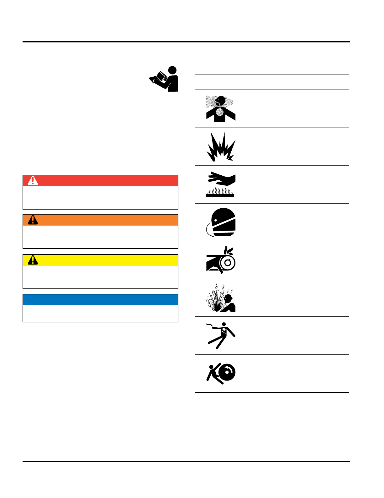
SAFETY SYMBOLS
The following table shows the potential hazards associated
with the operation of this equipment.
Symbol Safety Hazard
or NOTICE.
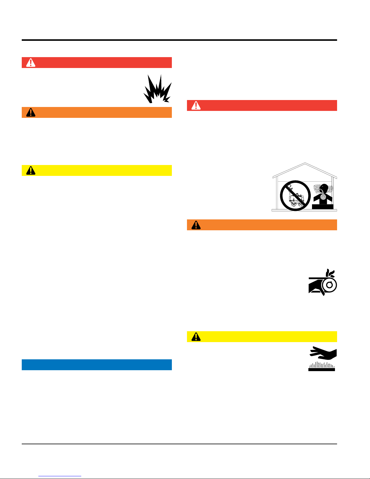
DANGER
Indicates a hazardous situation which, if not avoided,
WILL result in DEATH or SERIOUS INJURY.
WARNING
Indicates a hazardous situation which, if not avoided,
COULD result in DEATH or SERIOUS INJURY.
CAUTION
Indicates a hazardous situation which, if not avoided,
COULD result in MINOR or MODERATE INJURY.
Lethal exhaust gas hazards
Explosive fuel hazards
Burn hazards
Respiratory hazards
Rotating parts hazards
NOTICE
Pressurized fluid hazards
Addresses practices not related to personal injury.
Electric shock hazards
Runover hazards
PAGE 6 — V305EH VIBRATORY ROLLER • OPERATION AND PARTS MANUAL — REV. #1 (06/21/16)
Page 7
GENERAL SAFETY
NOTICE
This equipment should only be operated by trained and
Whenever necessary, replace nameplate, operation and
Manufacturer does not assume responsibility for any
accident due to equipment modifi cations. Unauthorized
use accessories or attachments that are not
recommended by Multiquip for this equipment. Damage
keep
Also, know the phone numbers
fi re department.
This information will be invaluable in the case of an
SAFETY INFORMATION
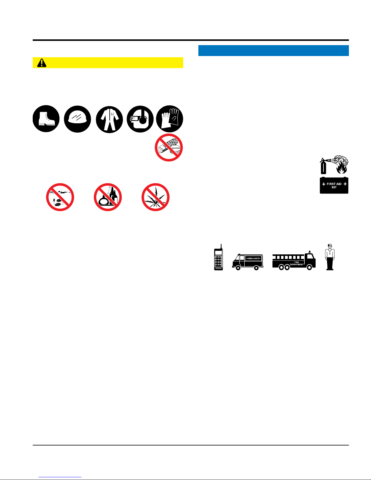
CAUTION
NEVER operate this equipment without proper protective
clothing, shatterproof glasses, respiratory protection,
hearing protection, steel-toed boots and other protective
devices required by the job or city and state regulations.
NEVER operate this equipment when not
feeling well due to fatigue, illness or when
under medication.
NEVER operate this equipment under the infl uence of
drugs or alcohol.
ALWAYS check the equipment for loosened threads or
bolts before starting.
DO NOT use the equipment for any purpose other than
its intended purposes or applications.
ALWAYS clear the work area of any debris, tools, etc.
that would constitute a hazard while the equipment is
in operation.
qualifi ed personnel 18 years of age and older.
safety decals when they become diffi cult read.
equipment modifi cation will void all warranties.
NEVER
to the equipment and/or injury to user may result.
ALWAYS know the location of the nearest
fi re extinguisher.
ALWAYS know the location of the nearest
fi rst aid kit.
ALWAYS know the location of the nearest phone or
a phone on the job site.
of the nearest ambulance, doctor and
emergency.
V305EH VIBRATORY ROLLER • OPERATION AND PARTS MANUAL — REV. #1 (06/21/16) — PAGE 7
Page 8
SAFETY INFORMATION
ROLLER SAFETY
DO NOT use worn-out hoses or couplings. Inspect daily.
store equipment properly when it is not being
used. Equipment should be stored in a clean, dry location
out of the reach of children and unauthorized personnel.
The engine fuel exhaust gases contain poisonous carbon
monoxide. This gas is colorless and odorless, and can
The engine of this equipment requires an adequate
operate this equipment
place hands or fingers inside engine
operate the engine with heat shields or
while the engine is hot. Hot oil will gush out of the oil
tank and severely scald any persons in the general area
Always turn the engine off before performing maintenance.
DANGER
NEVER operate the equipment in an explosive
atmosphere or near combustible materials. An
explosion or fi re could result causing severe
bodily harm or even death.
WARNING
NEVER disconnect any emergency or safety devices.
These devices are intended for operator safety.
Disconnection of these devices can cause severe injury,
bodily harm or even death. Disconnection of any of these
devices will void all warranties.
CAUTION
NEVER lubricate components or attempt service on a
running machine.
Never leave the roller unattended with the engine
running. Turn off engine.
Use chock blocks when parking roller on a grade.
Use extreme care when operating near obstructions, on
slippery surfaces, grades, and slide slopes.
ALWAYS
ENGINE SAFETY
DANGER
cause death if inhaled.
free fl ow of cooling air. NEVER
in any enclosed or narrow
area where free fl ow of the
air is restricted. If the air
fl ow is restricted it will cause
injury to people and property
and serious damage to the
equipment or engine.
WARNING
DO NOT
compartment when engine is running.
DANGEROUS
GAS FUMES
When reversing, particularly on the edges and banks
of ditches, as well as in front of obstaces, the operator
must stay in a standing position at a safe distance from
the machine.
When operating near any house/building or pipelines,
always check the effect of machine vibration. Stop work
if necessary.
DO NOT operate the roller with the covers open.
ALWAYS keep the machine away from other personnel
and obstacles. Always keep immediate are free of
bystanders.
NOTICE
ALWAYS keep the machine in proper running condition.
Fix damage to machine and replace any broken parts
immediately.
NEVER
guards removed.
Keep fi ngers, hands hair and clothing away
from all moving parts to prevent injury.
DO NOT remove the engine oil drain plug
of the roller.
CAUTION
NEVER touch the hot exhaust manifold,
muffl er or cylinder. Allow these parts to cool
before servicing equipment.
PAGE 8 — V305EH VIBRATORY ROLLER • OPERATION AND PARTS MANUAL — REV. #1 (06/21/16)
Page 9
SAFETY INFORMATION
NOTICE
DO NOT overfi ll tank, since spilled fuel could ignite if it
comes into contact with hot engine parts or sparks from
Store fuel in appropriate containers, in well-ventilated
drop the battery. There is a possibility that the
keep the battery charged. If the battery is not
charge battery if frozen. Battery can explode.
When frozen, warm the battery to at least 61°F (16°C).
recharge the battery in a well-ventilated
environment to avoid the risk of a dangerous concentration
NEVER run engine without an air fi lter or with a dirty air
fi lter. Severe engine damage may occur. Service air fi lter
frequently to prevent engine malfunction.
NEVER tamper with the factory settings
of the engine or engine governor. Damage
to the engine or equipment can result
if operating in speed ranges above the
maximum allowable.
NEVER tip the engine to extreme angles during lifting as
it may cause oil to gravitate into the cylinder head, making
the engine start diffi cult.
FUEL SAFETY
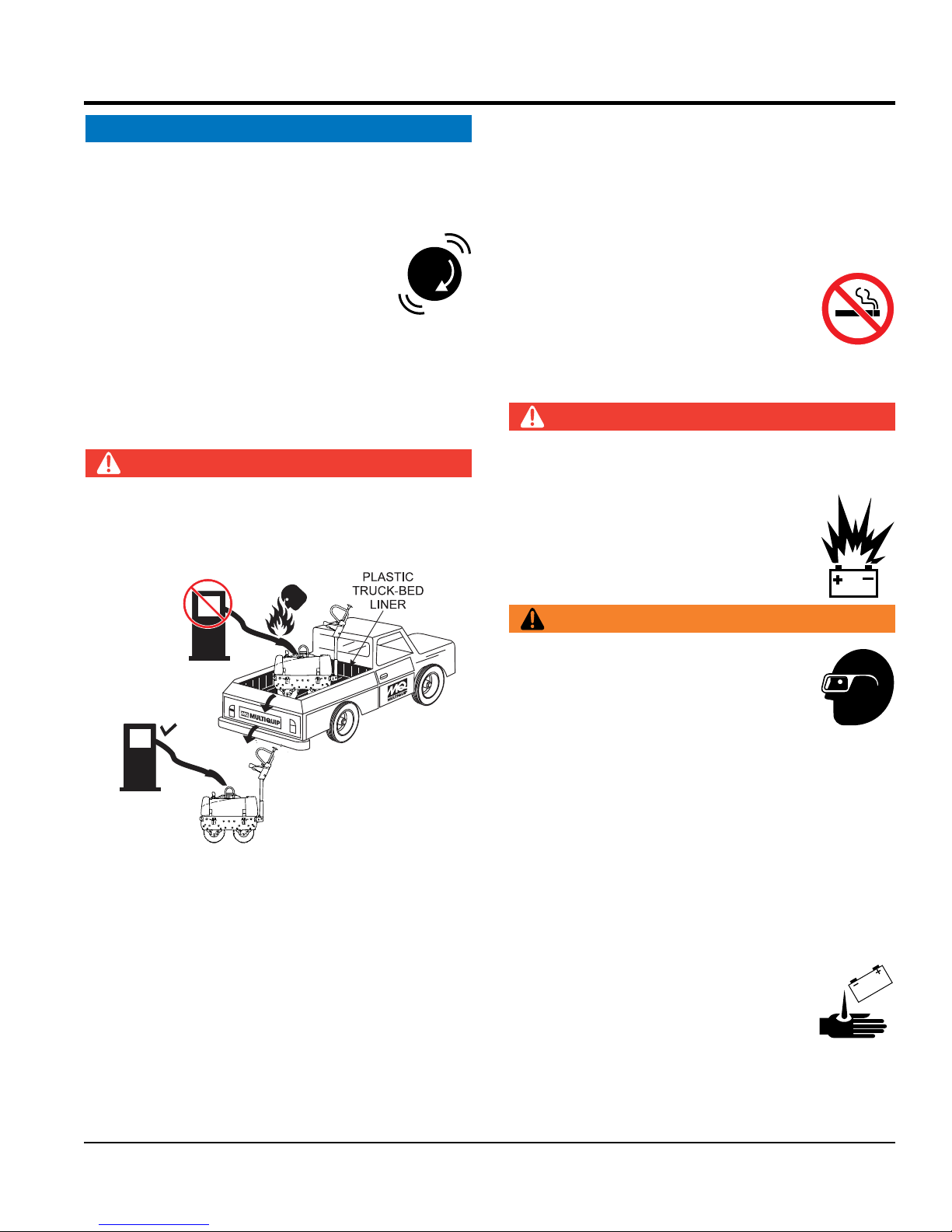
DANGER
DO NOT add fuel to equipment if it is placed inside truck
bed with plastic liner. Possibility exists of explosion or
fi re due to static electricity.
FUEL
the ignition system.
areas and away from sparks and fl ames.
NEVER use fuel as a cleaning agent.
DO NOT smoke around or near the
equipment. Fire or explosion could result
from fuel vapors or if fuel is spilled on a
hot engine.
BATTERY SAFETY (ELECTRIC START ONLY)
DANGER
DO NOT
battery will explode.
DO NOT expose the battery to open fl ames,
sparks, cigarettes, etc. The battery contains
combustible gases and liquids. If these
gases and liquids come into contact with a
fl ame or spark, an explosion could occur.
WARNING
FUEL
DO NOT start the engine near spilled fuel or combustible
fl uids. Diesel fuel is extremely fl ammable and its vapors
can cause an explosion if ignited.
ALWAYS refuel in a well-ventilated area, away from
sparks and open fl ames.
ALWAYS use extreme caution when working with
fl ammable liquids.
DO NOT fi ll the fuel tank while the engine is running
or hot.
ALWAYS wear safety glasses when
handling the battery to avoid eye irritation.
The battery contains acids that can cause
injury to the eyes and skin.
Use well-insulated gloves when picking up
the battery.
ALWAYS
charged, combustible gas will build up.
DO NOT
ALWAYS
of combustible gases.
If the battery liquid (dilute sulfuric acid)
comes into contact with clothing or skin,
rinse skin or clothing immediately with
plenty of water.
V305EH VIBRATORY ROLLER • OPERATION AND PARTS MANUAL — REV. #1 (06/21/16) — PAGE 9
Page 10

If the battery liquid (dilute sulfuric acid) comes into
contact with eyes, rinse eyes immediately with plenty
TRANSPORTING SAFETY
ENVIRONMENTAL SAFETY
use food or plastic containers to dispose of
pour waste, oil or fuel directly onto the ground,
of water and contact the nearest doctor or hospital to
seek medical attention.
CAUTION
ALWAYS disconnect the NEGATIVE battery terminal
before performing service on the equipment.
ALWAYS keep battery cables in good working condition.
Repair or replace all worn cables.
CAUTION
NEVER allow any person or animal to stand underneath
the equipment while lifting.
NOTICE
Before lifting, make sure that the equipment parts are not
damaged and screws are not loose or missing.
SAFETY INFORMATION
NOTICE
Dispose of hazardous waste properly.
Examples of potentially hazardous waste
are used motor oil, fuel and fuel fi lters.
DO NOT
hazardous waste.
DO NOT
down a drain or into any water source.
Use lifting equipment capable of lifting the weight of
the roller.
Always make sure crane or lifi tng device has been
properly secured to the lifting bail (hook) of the
equipment.
ALWAYS shutdown engine before transporting.
NEVER lift the equipment while the engine is running.
Tighten fuel tank cap securely and close fuel cock to
prevent fuel from spilling.
Use adequate lifting cable (wire or rope) of suffi cient
strength.
Use one point suspension hook and lift straight upwards
with suffi cient bearing capacity to prevent machine from
tilting or slipping.
DO NOT lift machine to unnecessary heights.
ALWAYS make sure that roller is secured correctly when
transporting on a trailer. Make sure all supports attaching
the roller to the trailer are tight.
PAGE 10 — V305EH VIBRATORY ROLLER • OPERATION AND PARTS MANUAL — REV. #1 (06/21/16)
Page 11

Table 1. Specifications (Vibratory Roller)
Centrifugal Force 3,800 lbf (16.9 kN)
Vibration Frequency 4,200 vpm (70 Hz)
Gradeablility (Maximum) 10% or 6°
Overall Length 88.5 in. (2,248 mm)
Overall Height 86.5 in. (2,197 mm)
Drum Diameter 22 in. (559 mm)
Drum Width 29 in. (737 mm)
Overall Width 35 in. (890 mm)
Operating Weight (Empty) 1168 lbs. (530 kg.)
Drive System Hydrostatic
Working Speed (Forward) 0 - 2.5 mph (0 - 4.0 kph)
SPECIFICATIONS
Working Speed (Reverse) 0 - 1.7 mph (0 - 2.7 kph)
Water Tank Capacity 7 gallons (26.5 liters)
Curb Clearance (Right) 16.5 in. (419 mm)
Curb Clearance (Left) 4.5 in. (114 mm)
Wall Clearance (Right) 0.75 in. (19 mm)
Wall Clearance (Left) 4.5 in. (114 mm)
Vibration Amplitude .019 in. (.48 mm)
V305EH VIBRATORY ROLLER • OPERATION AND PARTS MANUAL — REV. #1 (06/21/16) — PAGE 11
Page 12

SPECIFICATIONS
Table 2. Specifications (Engine)
Engine Model HONDA GX340UT2QAE2
Engine Type
Cylinder Bore X Stroke
Displacement 20.60 cu-in (337 cc)
Net power
(in accordance with SAE J1349*)
Fuel Tank Capacity 1.59 gallons (6.0 liters)
Fuel Unleaded Automobile Gasoline
Oil Capacity 1.16 quarts (1.1 liters)
Oil Alert System Ye s
Speed Control Method Centrifugal Flyweight Type
Starting Method Electric/Recoil Start
Dry Net Weight 68.4 lbs (31 Kg.)
Dimensions (L x W x H)
The power rating of the engine is the net power output tested on a production engine and
*
measured in accordance with SAE J1349 at 3,600 rpm (net power) and at 2,500 rpm (max net
torque). Mass production engines may vary from this value. Actual power output for the engine
installed in the machine will vary depending on numerous factors, including the operating speed
of the engine in application, environmental conditions, maintenance and other variables.
Air-cooled, 4 stroke, Overhead Valve, Single Cylinder,
Horizontal Shaft Gasoline Engine
3.2 in. X 2.5 in.
(88 mm x 64 mm.)
10.7 H.P. (8 kW)
15.0 x 17.7 X 17.4 in.
(380 X 450 X 443 mm.)
PAGE 12 — V305EH VIBRATORY ROLLER • OPERATION AND PARTS MANUAL — REV. #1 (06/21/16)
Page 13
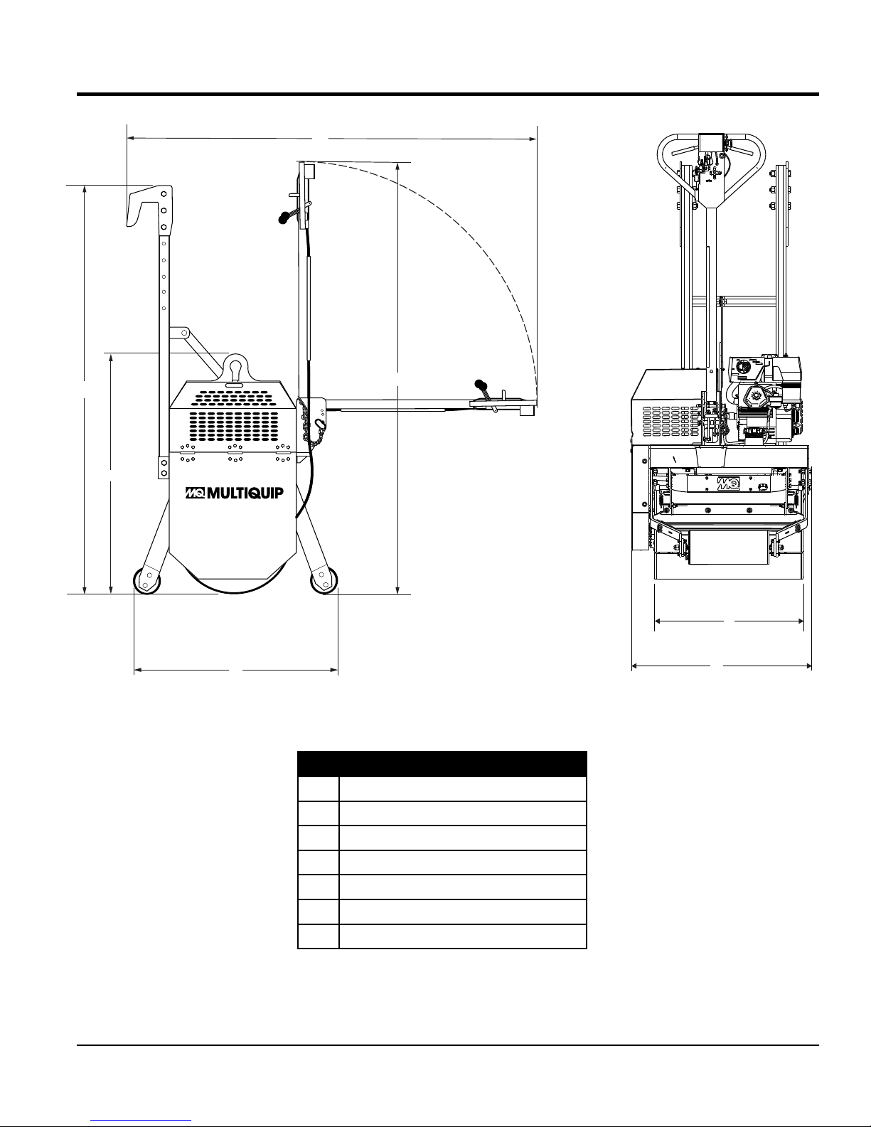
DIMENSIONS
C
G
F
E
D
A
B
Figure 1. V305EH Dimensions
Table 3. Dimensions (Roller)
A 29.0 in. (736.6 mm.)
V305EH VIBRATORY ROLLER • OPERATION AND PARTS MANUAL — REV. #1 (06/21/16) — PAGE 13
B 35.0 in. (889 mm.)
C 88.5 in. (2,248 mm.)
D 86.5 in. (2,197 mm.)
E 47 in. (1,193.8 mm.)
F 46.25 in. (1,175 mm.)
G 82.5 in. (2,095.5 mm.)
Page 14
GENERAL INFORMATION
The V305EH Vibratory Roller is a walk-behind vibratory
roller specifically designed for the compaction and patching
of asphalt type surfaces.
The compaction force is delivered by a 29-inch wide steel
drum with beveled edges to help prevent asphalt marring.
A fully enclosed hydrostatic drive system offers a variable
speed control as well as smooth acceleration and braking.
HYDROSTATIC DRIVE SYSTEM
This hydrostatic design offers a smooth performance,
because of a fully integrated hydrostatically-actuated drive
system, which provides a variable speed control under
varying load conditions. Power from the hydraulic drive
system is transferred via a drive belt to a gear reducer.
CONTROLS
The forward-reverse control lever (located on the handle)
operates the hydrostatic pump which governs the roller
speed and direction of travel. The neutral position of this
lever will cause the roller to stop. The vibration control, when
actuated, will apply a force of 4,200 vpm (vibrations per
minute). This vibratory feature is controlled by an eccentric
shaft via an operator controlled mechanical clutch.
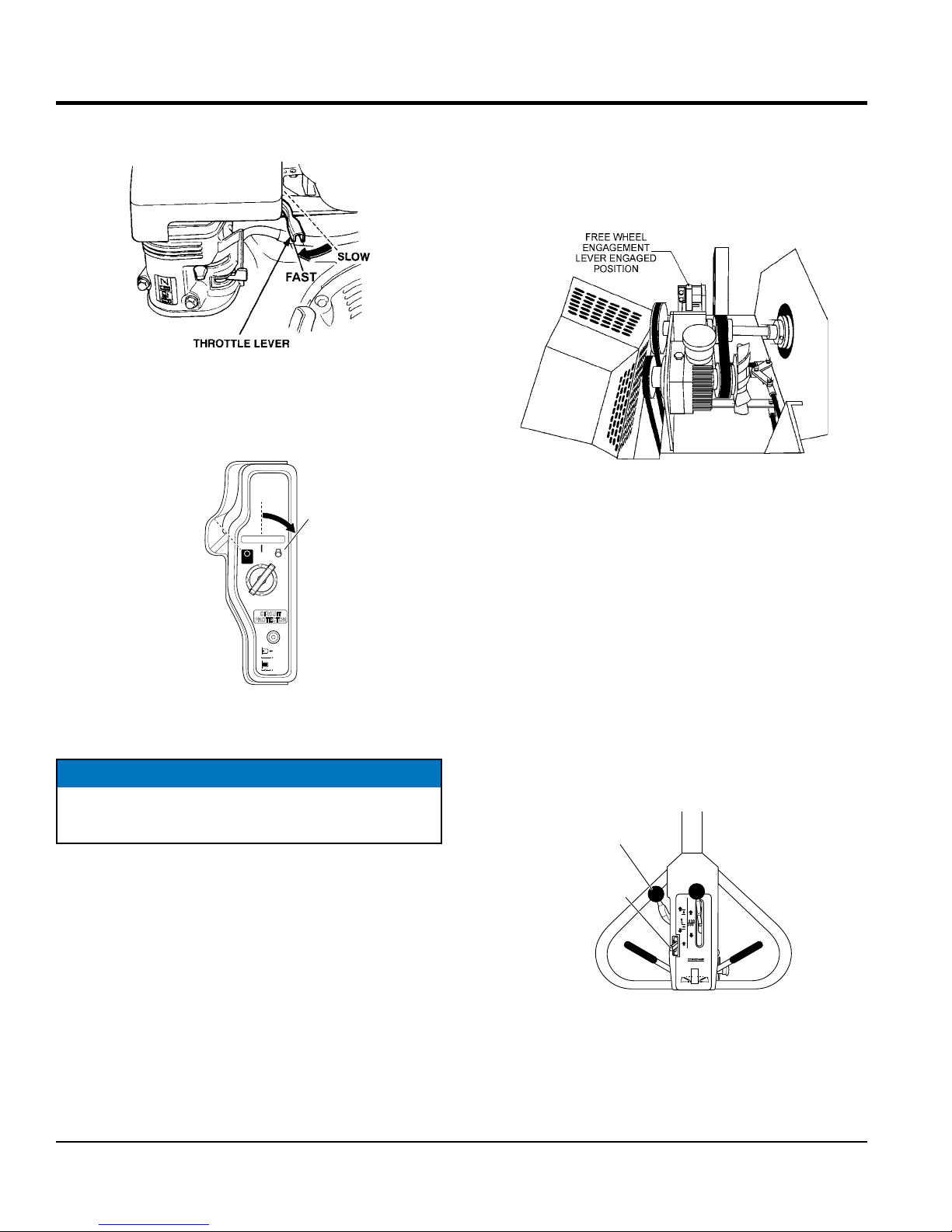
FREE WHEEL ENGAGEMENT LEVER
lever located on the handle with three water-flow adjustment
settings.
Before starting an asphalt rolling job, be sure all spray bar
holes are clear of dirt or foreign matter and are working.
Front and rear neoprene rubber scrapers are provided to
prevent the build-up of material between the drum and
the frame.
Always use clean fresh water in the water tank. A plastic
water reservoir is provided to prevent rust. It is suggested
to drain and flush water tank and spray bars every 30 days
to help the sprinkler system operate smoothly.
TRANSPORTATION
To help transport the roller from job site to job site,
adjustable transport hooks have been provided. These
transport hooks allow an operator to place the roller on
the tailgate of a dump truck without any assistance. The
control handle of the roller can be folded vertically for ease
of transport and storage.
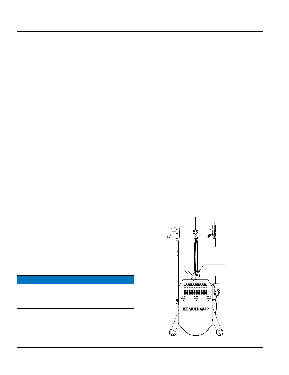
LIFTING THE ROLLER
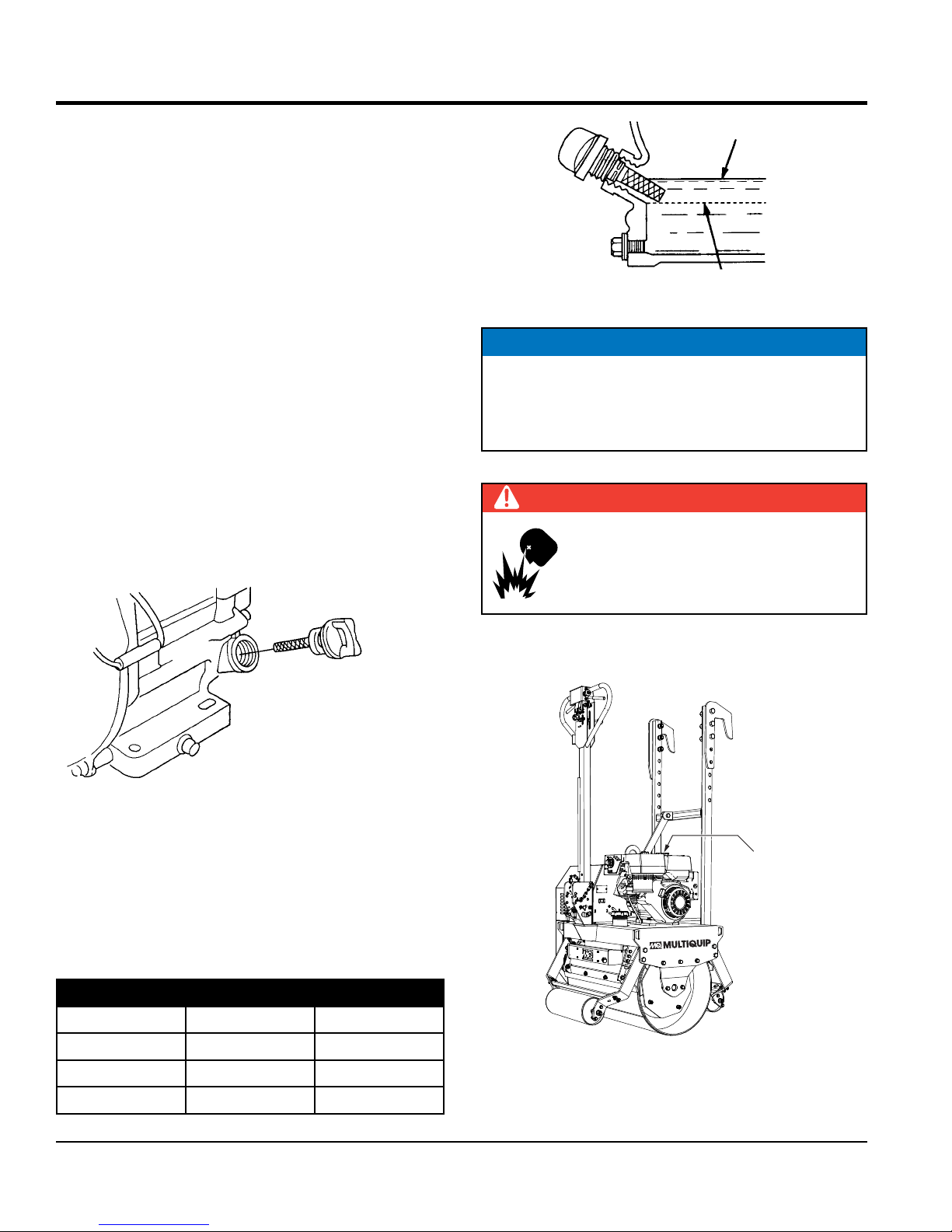
When lifting of the roller is required (Figure 2), attach a
suitable hook or shackle to the lifting eye of the roller. Make
sure the lifting device is capable of lifting 1,168 lbs (530 kg).
The hydrostatic transmission is equipped with a free wheel
engagement lever, which when actuated, allows the oil to
circulate freely within the roller. This allows the roller to be
moved without the engine running. This lever is only to be
used in the event the roller is disabled.
This lever is located on the that side of the transmission
which faces the front of the roller. It is actuated by placing
the handle into the side-lock position. To gain access to
this lever raise the roller's hood. DO NOT raise hood while
engine is running. STOP engine first.
NOTICE
In normal operating conditions the roller will not move
in a forward or reverse direction unless the free wheel
engagement lever is in the engage position (forward).
SPRINKLER SYSTEM
A 7 gallon (26.5 liters) water tank with a gravity feed spray
bar is provided for wetting the roll for asphaltic pavement
rolling. The delivery system is controlled by a mechanical
ATTACH
TO LIFTING
DEVICE
LIFTING
EYE
Figure 2. Lifting the Roller
PAGE 14 — V305EH VIBRATORY ROLLER • OPERATION AND PARTS MANUAL — REV. #1 (06/21/16)
Page 15
GENERAL INFORMATION
CAUTION
NEVER stand under, or get onto the roller while it is
being lifted or moved.
NOTICE
ONLY use steel ropes or chains that are capable of
lifting at least 2,000 lbs (907 kg).
NEVER use any other part of the roller for lifting
purposes. Use the lifting eye. Using other parts of the
roller for lifting will cause severe damage to the roller.
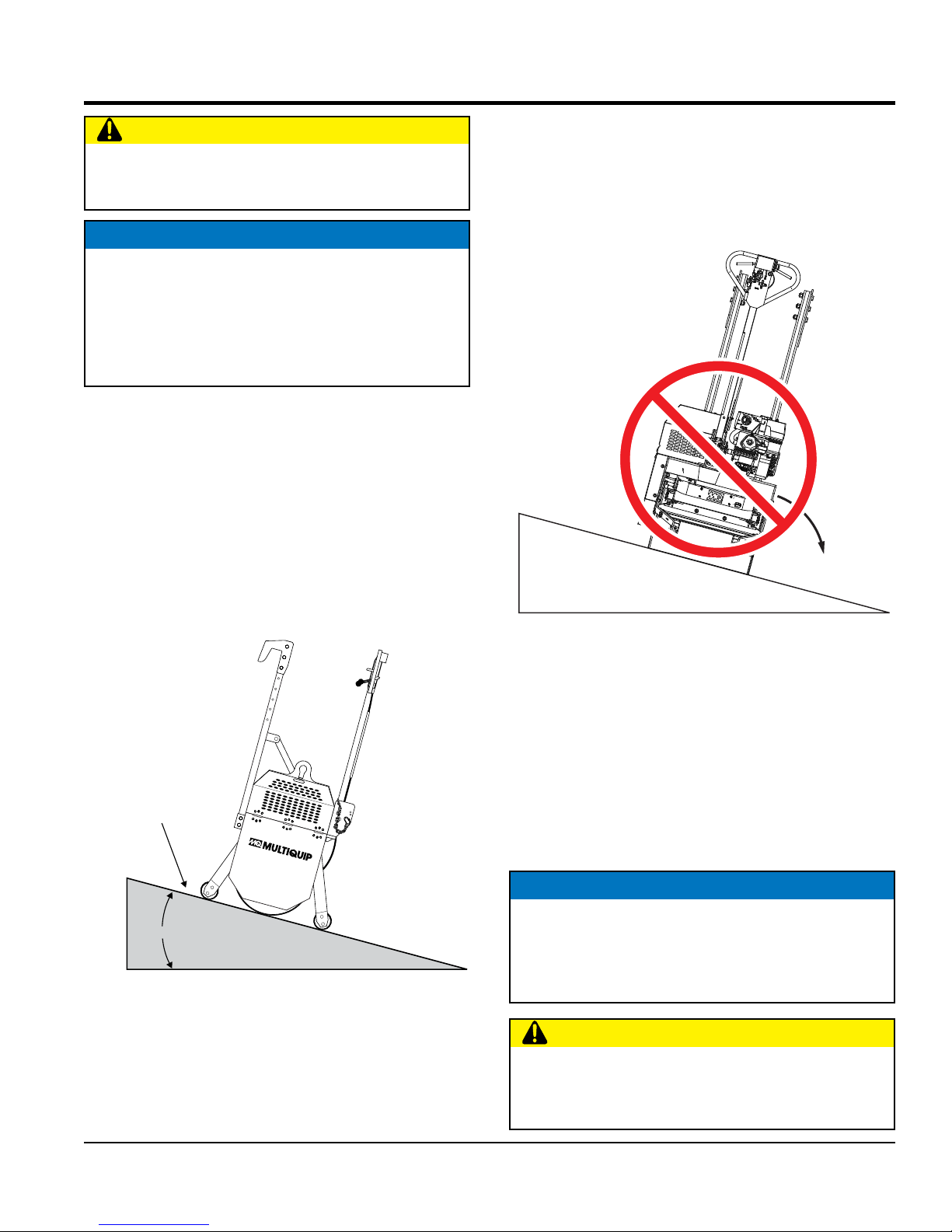
OPERATING ON SLOPES
Special care must be taken when operating the roller on
hills or slopes. There exist the possibility of serious injury to
the operator and severe damage to the roller in the event
of a roll over. ALWAYS operate the roller up and down hills
rather than from side to side. For safe operation, hillside
slopes should not exceed 6° (10% grade). See Figure 3
below.
Tipping (Rollovers)
NEVER operate the roller on side slopes (Figure 4). The
possibility exists of the roller tipping over (roll over), thus
causing bodily harm even death and serious damage to
the equipment.
SIDE TO SIDE
OPERATION
NOT RECOMMENDED
ROLL OVER
MAXIMUM SLOPE
10%
Figure 3. Recommended Slope
Figure 4. Tipping (Rollover)
In the event the roller does tip over, extreme care must be
taken to prevent damage to the engine. When the roller has
been tipped over, oil from the engine crankcase can flow
into the combustion chamber, which can severely damage
the engine the next time it is started.
IMMEDIATELY after a unit has tipped over upright the unit
as soon as possible to prevent oil from leaking into the
combustion chamber.
NOTICE
To prevent damage to the engine after a rollover, the
unit must NOT be started. NEVER start a unit after a
rollover. CONTACT your nearest authorized Multiquip
dealer for instructions or servicing.
CAUTION
NEVER operate the roller on side slopes. The roller
may tip over causing injury to personnel and severe
damage to the equipment.
V305EH VIBRATORY ROLLER • OPERATION AND PARTS MANUAL — REV. #1 (06/21/16) — PAGE 15
Page 16
COMPONENTS
13
2
1
3
12
8
14
15
5
4
6
9
10
11
16
7
20
17
19
18
PAGE 16 — V305EH VIBRATORY ROLLER • OPERATION AND PARTS MANUAL — REV. #1 (06/21/16)
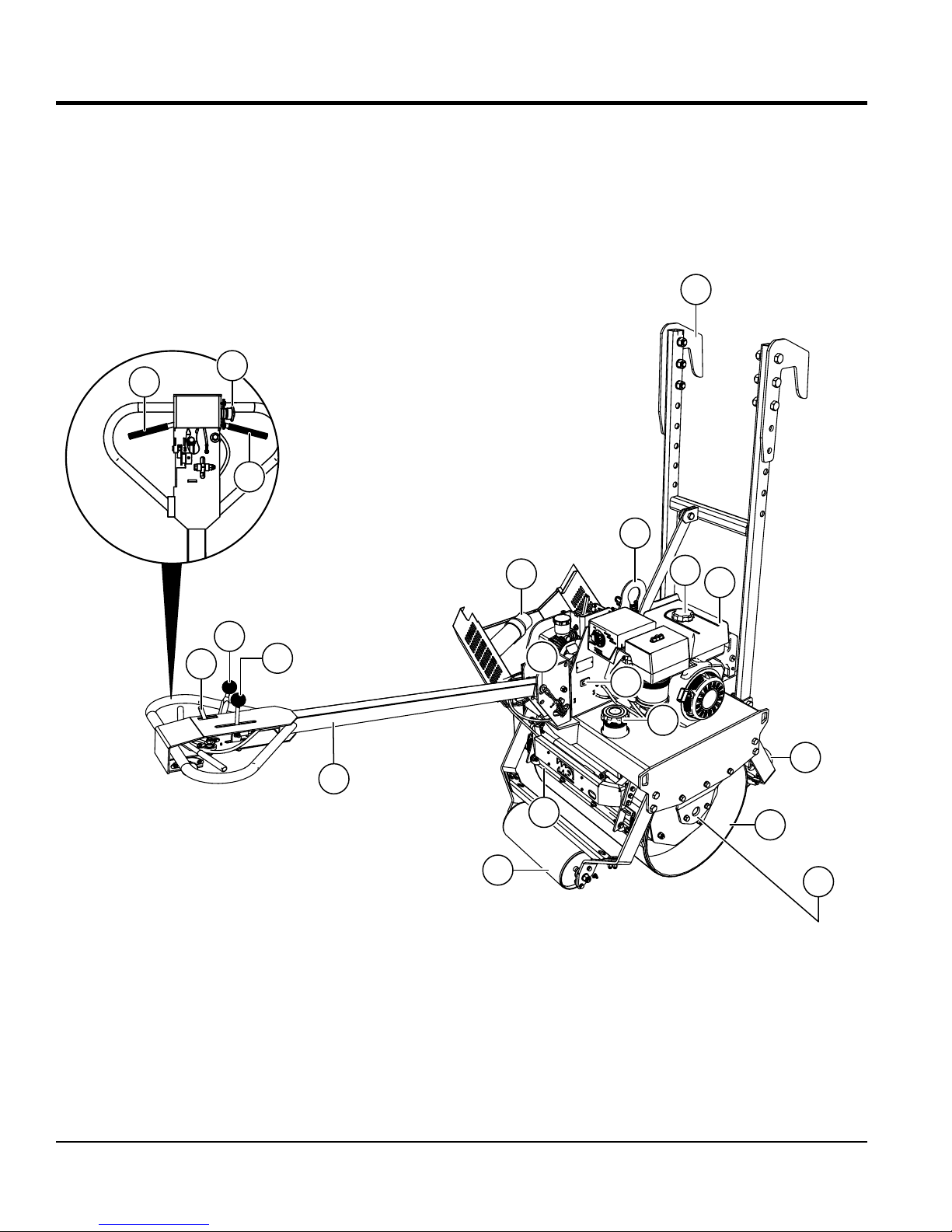
Figure 5. V305EH Components
Page 17

COMPONENTS
Figure 5 shows the location of the components for the
V305EH roller. The functions are described below:
1. Forward Travel Lever — This is a variable speed
control lever. Squeeze this lever to make the roller
travel in a forward direction.
2. Emergency Stop Button — Press this button to stop
the roller in the event of an emergency. DO NOT use
this button as a means of stopping the roller under
normal conditions. When starting the engine make
sure that this pushbutton switch is in the up position.
3. Reverse Travel Lever — This is a variable speed
control lever. Squeeze this lever to make the roller
travel in a reverse direction.
4. Water Shut-Off Release Control — Closes the water
valve.
5. Water Flow Adjustment Control — The lever located
on the handle opens the water valve. This control has
three adjustment settings: low, medium and high water
flow. In addition, a water filter is provided to prevent
foreign matter from clogging the spray bar holes. Clean
this filter as detailed in the maintenance section of this
manual.
12. Lifting Hook Eye — Attach a crane or lifting device
to this lifting hook eye. The lifting device should have
a lifting capacity of 1,168 lbs. (530 kg.)
13. Transport Hooks — These hooks are used in the
transportation of the roller (Figure 6). The hooks allow
the roller to hang over the tailgate of a dump truck.
TRANSPORT
HOOKS
Figure 6. Transport Hooks
14. Fuel Filler Port — Remove this cap to determine the
amount of fuel in the fuel tank. If low, add fuel through
this port.
6. Vibration Control Lever — Move this lever to the
ON position and the eccentric will produce a vibration
frequency of 4,200 vpm (vibrations per minute). Move
the lever to the OFF position to stop the vibrations.
7. Multi-Position Handle Bar — This bar can be set to
three different positions: stow, middle and low. When
transporting the roller, always have the handle bar in
the upright (stow) position.
8. Documentation Canister — Storage for documentation
and other information regarding the roller.
9. Handle Bar Release Pin — Remove this pin to
position the handle bar to the desired position. Make
sure to reinsert release pin and cotter pin after each
new position.
10. Hour/Tachometer — Indicates the number hours the
unit has been in use when engine is off and RPM when
engine is running.
11. Water Tank Filler Port — Remove this tethered cap
to determine the amount of water in the water tank. If
low, add clean water through this port. This water tank
is made of plastic to prevent rust, and holds 7 gallons
(26.5 liters) of water.
15. Engine — This roller uses a Honda GX340 engine. For
additional engine information read the engine Owner's
Manual supplied with the roller.
16. Front Stabilizer Roller — This roller aids the roller in
maintaining stability (prevents tipping) and simplifies
handing when maneuvering the roller.
17. Main Vibratory Roller — This roller is a 29-inch wide
steel drum with beveled edges. The beveled edges
help prevent asphalt marring. The maintenance-free
exciter reduces service time.
18. Zerk Fittings — Lube and grease these fittings as
recommended in the maintenance section of this
manual.
19. Rear Stabilizer Roller — This roller aids the roller in
maintaining stability (prevents tipping) and simplifies
handling when maneuvering the roller.
20. Scraper Blades — The neoprene rubber blades help
prevent the buildup of material between the drum
and frame. The blades are spring-loaded for easy
replacement.
V305EH VIBRATORY ROLLER • OPERATION AND PARTS MANUAL — REV. #1 (06/21/16) — PAGE 17
Page 18
1
COMPONENTS
2
6
3
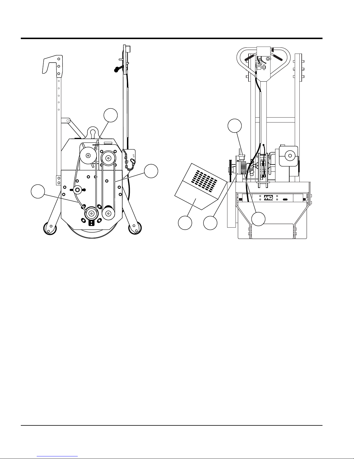
Figure 7. V305EH Additional Components
Figure 7 shows the location of additional components
for the V305EH compaction roller. The function of each
component or control is described below:
1. Vibration Drive V-Belt — This belt is require to make
the roller vibrate. Check this V-belt as outlined in the
maintenance section of this manual.
2. Free Wheel Engagement Lever — Under normal
conditions this lever should be place in the forward
position (engaged).
In the event the roller becomes disabled (will not start)
and must be moved, place the lever in the side position
(disengaged). This will allow the roller drum to rotate
(free wheel).
IMPORTANT: This lever is only to be used in cases
where the roller has be disabled. In normal operating
conditions this lever should be left in the engaged
position (forward).
4
3. Travel Drive V-Belt — This belt is require to make the
roller travel in a forward or reverse direction. Check
this V-belt as outlined in the maintenance section of
this manual.
4. Compartment Hood — Open this hood (tool-free) to
gain access to the V-belts, hydrostatic pump, coupling
components, free wheel engagement lever etc.
5. Hydrostatic Pump — Provides hydraulic pressure to
the drive system.
6. Hydrostatic Fluid Reservoir — Fill this reservoir with
hydrostatic transmission fluid. Fill with ExxonMobil
Nuto 46 or equivalent.
7. Cogged-Drive Belt — This belt is used with the
hydraulic pump. Check this cogged drive belt as
outlined in the maintenance section of this manual.
5
7
PAGE 18 — V305EH VIBRATORY ROLLER • OPERATION AND PARTS MANUAL — REV. #1 (06/21/16)
Page 19
BASIC ENGINE
10
9
8
7
6
5
4
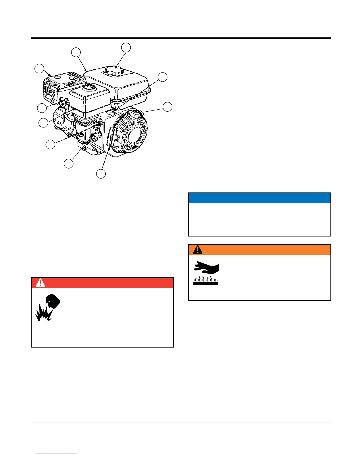
Figure 8. Engine Components
1
2
3
INITIAL SERVICING
The engine (Figure 8) must be checked for proper
lubrication and filled with fuel prior to operation. Refer to the
engine manufacturer’s manual for instructions and details
of operation and servicing.
2. Throttle Lever — Used to adjust engine RPM speed
(lever advanced forward SLOW, lever back toward
operator FAST).
3. Engine ON/OFF Switch — ON position permits engine
starting, OFF position stops engine operations.
4. Recoil Starter (pull rope) — Manual-starting method.
Pull the starter grip until resistance is felt, then pull
briskly and smoothly.
5. Fuel Valve Lever — OPEN to let fuel flow, CLOSE to
stop the flow of fuel.
6. Choke Lever — Used in the starting of a cold engine,
or in cold weather conditions. The choke enriches the
fuel mixture.
7. Air Cleaner — Prevents dirt and other debris from
entering the fuel system. Remove wing-nut on top of
air filter cannister to gain access to filter element.
NOTICE
Operating the engine without an air filter, with a
damaged air filter, or a filter in need of replacement
will allow dirt to enter the engine, causing rapid engine
wear.
1. Fuel Filler Cap — Remove this cap to add unleaded
gasoline to the fuel tank. Make sure cap is tightened
securely. DO NOT over fill.
DANGER
Adding fuel to the tank should be done
only when the engine is stopped and has
had an opportunity to cool down. In the
event of a fuel spill, DO NOT attempt to
start the engine until the fuel residue has
been completely wiped up, and the area surrounding
the engine is dry.
WARNING
Engine components can generate extreme
heat. To prevent burns, DO NOT touch
these areas while the engine is running or
immediately after operating. NEVER operate
the engine with the muffler removed.
8. Spark Plug — Provides spark to the ignition system.
Set spark plug gap to 0.6 - 0.7 mm (0.028 - 0.031 inch)
Clean spark plug once a week.
9. Muffler — Used to reduce noise and emissions.
10. Fuel Tank — Holds unleaded gasoline. For additional
information refer to engine owner's manual.
V305EH VIBRATORY ROLLER • OPERATION AND PARTS MANUAL — REV. #1 (06/21/16) — PAGE 19
Page 20
INSPECTION
BEFORE STARTING
1. Read safety information at the beginning of manual.
2. Remove dirt and dust, particularly in the engine cooling
air inlet, carburetor and air cleaner.
3. Check the air filter for dirt and dust. If air filter is dirty,
replace air filter with a new one.
4. Check carburetor for external dirt and dust. Clean with
dry compressed air.
5. Check fastening nuts and bolts for tightness.
6. Understand the geographical features and regulations
of the job site.
ENGINE OIL CHECK
1. To check the engine oil level, place the machine on
secure level ground with the engine stopped.
2. Remove the filler dipstick from the engine oil filler hole
(Figure 9) and wipe clean.
UPPER LIMIT
LOWER LIMIT
Figure 10. Engine Oil Level
NOTICE
The V305EH roller has an Oil Alert System. This
system will automatically stop the in the event of low
oil level. ALWAYS be sure to check the engine oil level
prior to starting the engine.
FUEL CHECK
DANGER
Motor fuel is highly flammable and can be
dangerous if mishandled. DO NOT smoke
while refueling. DO NOT attempt to refuel
the pump if the engine is hot or running.
Figure 9. Engine Oil Dipstick
3. Insert and remove the dipstick without screwing it into
the filler neck. Check the oil level shown on the dipstick
(Figure 10).
4. If the oil level is low, fill to the edge of the oil filler hole
with the recommended oil type (Table 4). Maximum oil
capacity is 1.16 quarts (1.1 liters).
Table 4. Oil Type
Season Temperature Oil Type
Summer 25°C or Higher SAE 10W-30
Spring/Fall 25°C~10°C SAE 10W-30/20
Winter 0°C or Lower SAE 10W-10
1. Remove the fuel cap of the filler port located on top of
the engine fuel tank (Figure 11).
FUEL TANK
FILLER PORT
Figure 11. Fuel Tank Filler Port
2. Visually inspect to see if the fuel level is low. If fuel is
low, replenish with unleaded gasoline using a strainer
PAGE 20 — V305EH VIBRATORY ROLLER • OPERATION AND PARTS MANUAL — REV. #1 (06/21/16)
Page 21
INSPECTION
for filtration. DO NOT top-off fuel. Wipe up any spilled
fuel immediately!
WATER TANK CHECK
1. Check the water tank to see if filled. Add water if
necessary. See Figure 12.
WATER TANK
FILLER PORT
V-BELT CHECK
DANGER
ALWAYS keep hands and fingers away
from pinch points. DO NOT allow anyone
to reach in on dangerous sections of the
machine to avoid any accidents.
1. Check the tension of the vibratory and travel V-belts
(Figure 14). This tension can be checked by the amount
of deflection when the belt is pressed midway between
the two pulleys. The deflection of the travel belt should
be approximately 3/4 of an inch (2 cm). The vibratory
V-belt should have a deflection of approximately 2 to
2-3/4 inches (5 to 7 cm).
COGGED
DRIVE BELT
VIBRATORY
V-BELT
Figure 12. Checking Water Tank
2. Verify that valve for the water tank is closed (handle
control).
HYDRAULIC SYSTEM CHECK
1. Visually inspect the hydraulic fluid in the hydraulic
reservoir (Figure 13). If the hydraulic fluid is low, fill
the reservoir with ExxonMobil Nuto 46 or equivalent.
The correct hydraulic fluid level will be indicated on the
reservoir.
HYDRAULIC FLUID
FILLER PORT
HYDRAULIC OIL LEVEL HOT
IMPORTANT
HYDRAULIC OIL LEVEL COLD
TRAVEL
V-BELT
Figure 14. Checking V-Belts
2. Check the tension of the cogged V-belt (hydrostatic
pump). This tension can be checked by the amount of
deflection when the belt is pressed midway between
the two pulleys. The deflection of the travel belt should
be approximately 1/2 of an inch (1.27 cm).
Figure 13. Hydraulic Reservoir Filler Port
V305EH VIBRATORY ROLLER • OPERATION AND PARTS MANUAL — REV. #1 (06/21/16) — PAGE 21
Page 22
GEARBOX LUBRICATION
HITCH PIN
1. Remove the oil fill drain plug on the gearbox (Figure 15). If
the oil level is correct, oil will begin to leak out. Retighten
drain plug.
INSPECTION
HANDLE
BAR
GEARBOX
FILL PLUG
AND
LEVEL CHECK
1. PARK POSITION
2. HIGH POSITION
3. MIDDLE POSITION
3. LOW POSITION
RELEASE
PIN
Figure 16. Handle Positions 1
GEARBOX
DRAIN PLUG
Figure 15. Gearbox Fill and Drain Plugs
2. If the level of the oil in the gearbox is low, no oil will leak
out when the drain plug is removed. Add gearbox oil, type
SAE 90, through this drain opening. Fill until oil begins
to leak out from the drain opening. Retighten drain plug.
It is recommended that oil be changed every 300 hours
of operation.
HANDLE BAR ADJUSTMENT
1. Adjustment of the handle bar is made by removing
the handle bar hitch pin, then pulling the release pin.
2. Once released pin has been removed, position handle
bar to desired height (Figure 16 and Figure 17).
3. Insert release pin and lock with hitch pin.
PAGE 22 — V305EH VIBRATORY ROLLER • OPERATION AND PARTS MANUAL — REV. #1 (06/21/16)
POSITION 1 (PARK)
Figure 17. Handle Positions 2
POSITION 2
(HIGH)
POSITION 2
(MIDDLE)
POSITION 2
(LOW)
Page 23
OPERATION
This section is intended to assist the operator with the initial
startup of the unit. It is extremely important that this section be
read carefully before using the roller in the field. DO NOT use
your roller until this section is thoroughly understood.
WARNING
Failure to understand the operation of the roller could
result in severe damage to the unit or personal injury.
CAUTION
NEVER operate the roller in a confined
area or enclosed area structure that does
not provide ample free flow of air.
1. ALWAYS make sure that the emergency stop button
(Figure 18) is pulled all the way out (disengage).
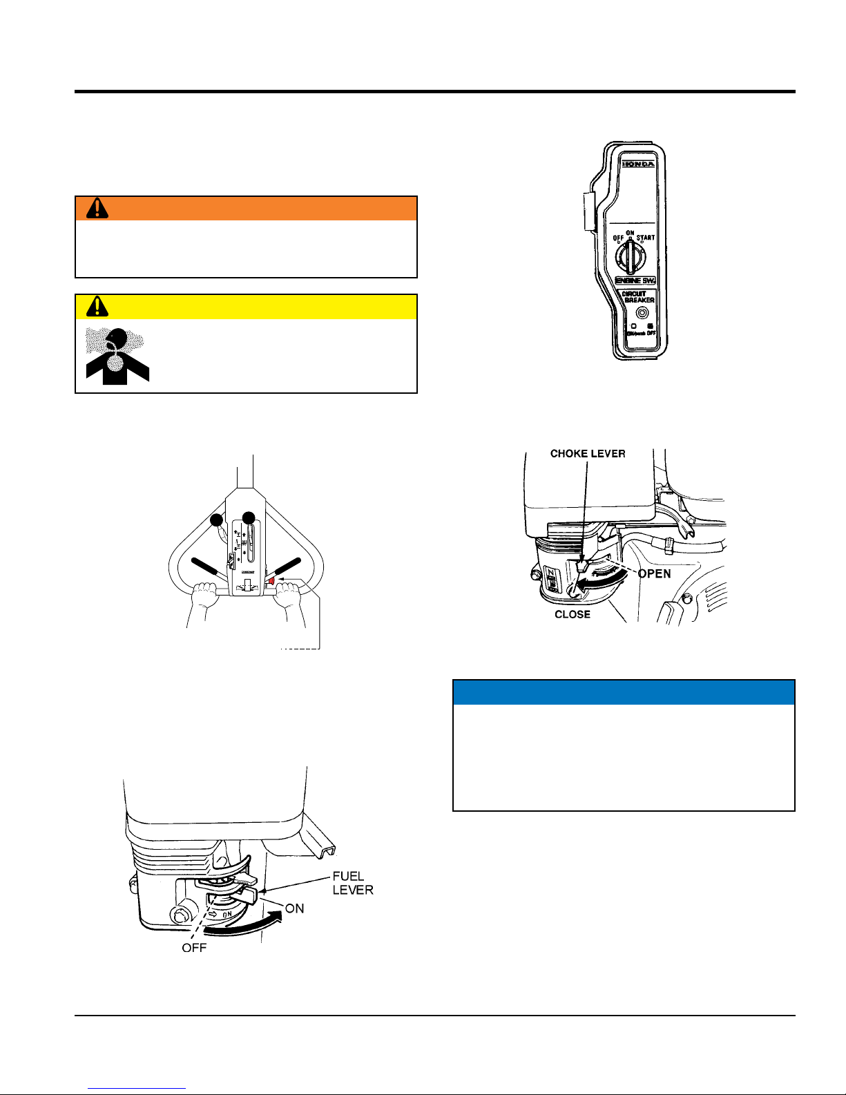
3. Place the Engine ON/OFF switch (Figure 20) in the
"ON" position.
Figure 20. Engine ON/OFF Switch
4. To start a cold engine, move the choke lever (Figure 21)
to the CLOSED position.
804100
VIBRATION
CLOSE
STOP
CERRADO
PARO
VIBRACION
SPRINKLER
ROCIADOR
OPEN
ABIERTO
VIBRATION
VIBRACION
PUSH
TO
RELEASE
EMPUJE
PARA
LIBERAR
MULTIQUIP COMPANY, 18910 WILMINGTON AVENUE
CARSON, CALIFORNIA 90746
310-537-3700, 800/421-1244 NATIONWIDE, FAX: 310-537-3927
FORWARD
REVERSE
AVANCE
REVERSA
N
EMERGENCY
STOP BUTTON
PULL OUT
TO DISENGAGE
Figure 18. Emergency Stop Button
2. Move the fuel lever (Figure 19) to the ON position.
Figure 21. Choke Lever
NOTICE
The CLOSED position of the choke lever enriches the
fuel mixture for starting a COLD engine. The OPEN
position provides the correct fuel mixture for normal
operation after starting, and for restarting a warm
engine.
Figure 19. Fuel Lever
V305EH VIBRATORY ROLLER • OPERATION AND PARTS MANUAL — REV. #1 (06/21/16) — PAGE 23
Page 24
OPERATION
SHUT-OFF
5. Move the throttle lever (Figure 22) away from the slow
position, about 1/3 of the way toward the fast position.
Figure 22. Throttle Lever
6. Turn the Engine ON/OFF switch on the engine to the
START position (Figure 23). Release the key when
engine starts and key will return to the ON position.
ENGINE SW.
ON
STARTOFF
FREE WHEEL ENGAGEMENT LEVER
Before the roller can be put into operation, check and make
sure that the free wheel engagement lever (Figure 24)
is in the engaged position (forward). Lift the compartment
hood to gain access to this lever.
Figure 24. Freewheel Engagement Lever
WATER SPRINKLER SYSTEM
If the water sprinkler is going to be used for a roll of asphalt
paving, fill the water tank with clean water.
CIRCUIT
PROTECTOR
ON
OFF
Figure 23.
Engine ON/OFF Switch (START)
NOTICE
DO NOT keep the ignition switch in the START position
for more than 5 seconds.
7. If the engine has started allow switch to return to ON
position, then slowly return the choke lever (Figure
22) to the OPEN position. If the engine has not started
repeat steps 1 through 6.
8. Before the roller is placed into operation, run the engine
for several minutes. Check for fuel leaks, and noises
associated with a loose guard or covers.
1. Push the water shut-off release control to the release
position (Figure 25).
2. Move the water flow adjustment control to the OPEN
position.
3. The water flow adjustment control has three
adjustments. Move control to set to low, medium, or
high water flow.
4. Return the water shut-off release control to the CLOSE
position when water is not required.
WATER FLOW
ADJUSTMENT
CONTROL
WATER
RELEASE
CONTROL
Figure 25. Water Flow Adjustment
804100
VIBRATION
CLOSE
STOP
CERRADO
PARO
VIBRACION
SPRINKLER
ROCIADOR
OPEN
ABIERTO
VIBRATION
VIBRACION
PUSH
TO
RELEASE
EMPUJE
PARA
LIBERAR
MULTIQUIP COMPANY, 18910 WILMINGTON AVENUE
CARSON, CALIFORNIA 90746
310-537-3700, 800/421-1244 NATIONWIDE, FAX: 310-537-3927
FORWARD
REVERSE
AVANCE
REVERSA
N
9. All rolling is done at full throttle. Your engine governor
has been set at the factory to ensure an optimum
speed setting.
PAGE 24 — V305EH VIBRATORY ROLLER • OPERATION AND PARTS MANUAL — REV. #1 (06/21/16)
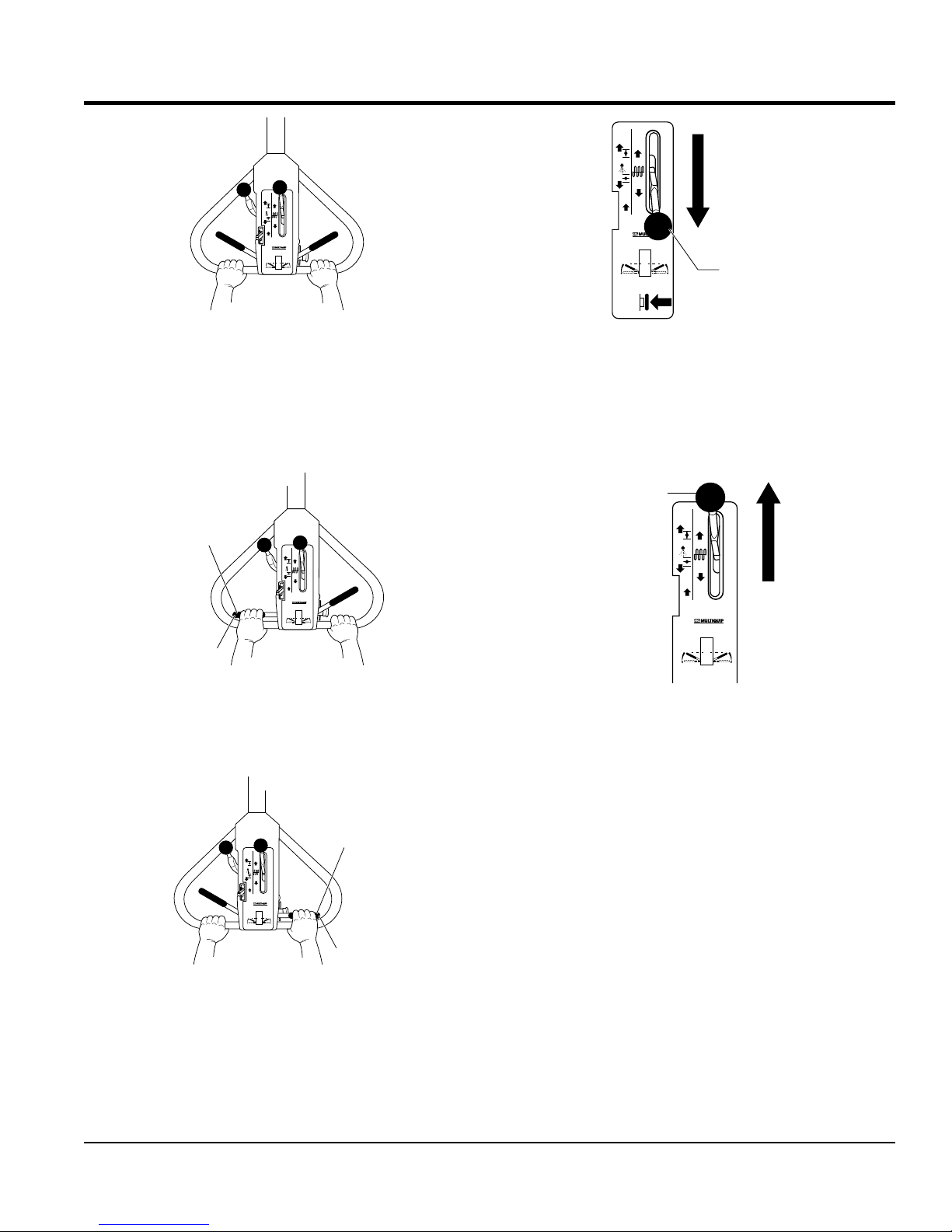
TRAVEL LEVERS
1. With the engine running, both forward and reverse
travel levers (Figure 26) should be in their neutral
positions.
Page 25
804100
VIBRATION
CLOSE
STOP
CERRADO
PARO
VIBRACION
SPRINKLER
ROCIADOR
OPEN
ABIERTO
VIBRATION
VIBRACION
PUSH
TO
RELEASE
EMPUJE
PARA
LIBERAR
MULTIQUIP COMPANY, 18910 WILMINGTON AVENUE
CARSON, CALIFORNIA 90746
310-537-3700, 800/421-1244 NATIONWIDE, FAX: 310-537-3927
FORWARD
REVERSE
AVANCE
REVERSA
N
Figure 26. Travel Levers (Neutral Position)
2. Squeeze the left travel lever (Figure 27) to move roller
in a forward direction. Squeezing the lever all the way
towards the operator will achieve maximum speed. Use
a smooth squeezing action on the drive control lever to
prevent abrupt takeoffs.
FORWARD
CONTROL
LEVER
SQUEEZE
804100
VIBRATION
CLOSE
STOP
CERRADO
PARO
VIBRACION
SPRINKLER
ROCIADOR
OPEN
ABIERTO
VIBRATION
VIBRACION
PUSH
TO
RELEASE
EMPUJE
PARA
LIBERAR
MULTIQUIP COMPANY, 18910 WILMINGTON AVENUE
CARSON, CALIFORNIA 90746
310-537-3700, 800/421-1244 NATIONWIDE, FAX: 310-537-3927
FORWARD
REVERSE
AVANCE
REVERSA
N
OPERATION
804100
VIBRATION
CLOSE
STOP
CERRADO
PARO
VIBRACION
SPRINKLER
ROCIADOR
OPEN
ABIERTO
VIBRATION
VIBRACION
PUSH
TO
RELEASE
EMPUJE
PARA
LIBERAR
MULTIQUIP COMPANY, 18910 WILMINGTON AVENUE
CARSON, CALIFORNIA 90746
310-537-3700, 800/421-1244 NATIONWIDE, FAX: 310-537-3927
FORWARD
REVERSE
AVANCE
REVERSA
N
PUSH
TO STOP
PUSH
EMPUJE
EMPUJAR
PARA PARAR
Figure 29. Vibratory Control Lever (ON)
SHUTDOWN
1. Place the vibration control lever (Figure 30) on the roller
to the OFF position (vibration stops).
VIBRATION
CONTROL
LEVER
CLOSE
CERRADO
SPRINKLER
ROCIADOR
ABIERTO
RELEASE
EMPUJE
LIBERAR
FORWARD
VIBRATION
STOP
PARO
VIBRACION
OPEN
VIBRATION
VIBRACION
PUSH
TO
PARA
MULTIQUIP COMPANY, 18910 WILMINGTON AVENUE
CARSON, CALIFORNIA 90746
310-537-3700, 800/421-1244 NATIONWIDE, FAX: 310-537-3927
AVANCE
N
ON
POSITION
VIBRATION
CONTROL
LEVER
804100
STOP
POSITION
REVERSE
REVERSA
Figure 27. Forward Travel Lever
3. Squeeze the right travel lever (Figure 28) to move the
roller in a reverse direction. Use a smooth squeezing
action on the drive control lever to prevent abrupt takeoffs.
REVERSE
CONTROL
804100
VIBRATION
CLOSE
STOP
CERRADO
PARO
VIBRACION
SPRINKLER
ROCIADOR
OPEN
ABIERTO
VIBRATION
VIBRACION
PUSH
TO
RELEASE
EMPUJE
PARA
LIBERAR
MULTIQUIP COMPANY, 18910 WILMINGTON AVENUE
CARSON, CALIFORNIA 90746
310-537-3700, 800/421-1244 NATIONWIDE, FAX: 310-537-3927
FORWARD
REVERSE
AVANCE
REVERSA
N
LEVER
SQUEEZE
Figure 28. Reverse Travel Lever
VIBRATORY CONTROL
1. For vibratory action, with the engine running (full
speed) place the vibratory control lever (Figure 29) to
the ON position. The roller will now produce a vibratory
frequency of 4,400 vps.
Figure 30. Vibratory Control Lever (OFF)
2. Place the water valve in the CLOSED position (if used).
3. Place the engine throttle lever in the slow position,
and let the engine idle for 3-5 minutes.
4. Place the engine ON/OFF switch in the OFF position
and remove the key. Place the key in a safe place.
TRANSPORTING
1. Always make sure that the machine is shut off while
being transported.
2. Check that the fuel cap is properly closed and tightened.
3. When traveling long distances or on rugged terrain,
drain the fuel of the machine before transporting.
4. Tie down the machine securely on the transportation
so that it will not move or topple over.
V305EH VIBRATORY ROLLER • OPERATION AND PARTS MANUAL — REV. #1 (06/21/16) — PAGE 25
Page 26
MAINTENANCE
0.024-0.028 IN.
GAP
OIL FILLER CAP
BOLT
CAUTION
Inspection and other services should always be carried
out on hard and level ground with the engine shutdown.
INSPECTION AND MAINTENANCE SERVICE TABLES
To make sure your vibratory roller is always in good
working condition before using, carry out the maintenance
inspection procedures.
Table 5. Machine Inspection
ITEM HOURS OF OPERATION
Loose or Missing Screws Every 8 hours (every day)
Damaged Parts Every 8 hours (every day)
Function of Controlling
System Part
Eaton Hydrostatic
Transmission
Vibrator Oil Check Every 50 hours
Every 8 hours (every day)
Every 100 hours
DAILY SERVICE
1. Check for leakage of fuel or oil.
2. Check for loose screws and tighten to the proper
torque:
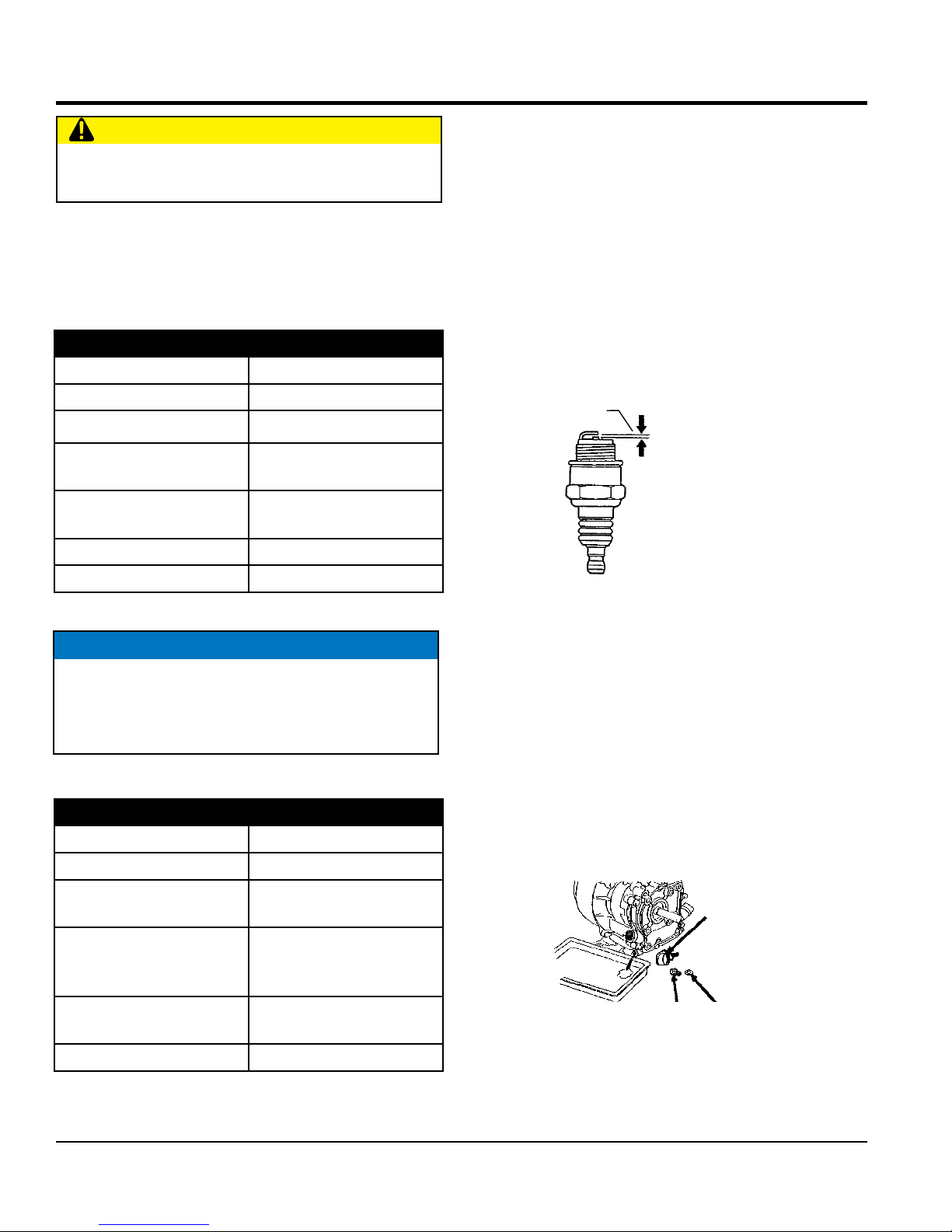
SPARK PLUG
1. Remove and clean the spark plug (Figure 31).
2. Adjust the spark gap to 0.024 ~0.028 inch (0.6~0.7
mm). This unit has electronic ignition, which requires
no adjustments.
(0.6-0.7 MM.)
V-belt (clutch) Check Every 200 hours
NOTICE
These inspection intervals are for operation under
normal conditions. Adjust your inspection intervals
based on the number of hours the roller is in use, and
your particular working conditions.
Table 6. Engine Check
ITEM HOURS OF OPERATION
Oil or Fuel Leak Every 8 hours (every day)
Tightness of Fastening
Threads
Engine Oil Check and
Replenishment
Engine Oil Replacement
Every 8 hours (every day)
Every 8 hours (every day)
(Replenish to specified
maximum level)
After first 25 hours then
every 50 to 100 hours
Figure 31. Spark Plug Gap
ENGINE OIL
1. Drain the engine oil when the oil is warm as shown in
Figure 32.
2. Remove the oil drain bolt and sealing washer and allow
the oil to drain into a suitable container.
3. Replace engine oil with recommended type oil as listed
in Table 4. Engine oil capacity is 1.16 quarts (1.1 liters).
DO NOT overfill.
4. Install drain bolt with sealing washer and tighten
securely.
DIPSTICK
DRAIN
SEALING
WASHER
Air Filter Cleaning Every 50 hours
PAGE 26 — V305EH VIBRATORY ROLLER • OPERATION AND PARTS MANUAL — REV. #1 (06/21/16)
Figure 32. Engine Oil (Draining)
Page 27
MAINTENANCE
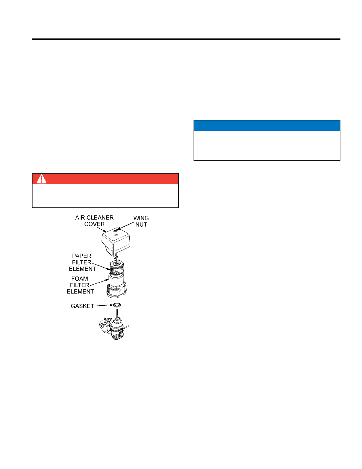
ENGINE AIR CLEANER
1. Remove the air cleaner cover and foam filter element
as shown in Figure 33.
2. Tap the paper filter element (Figure 33) several times
on a hard surface to remove dirt, or blow compressed
air [not exceeding 30 psi (207 kPa, 2.1 kgf/cm2)]
through the filter element from the air cleaner case
side. NEVER brush off dirt. Brushing will force dirt
into the fibers. Replace the paper filter element if it is
excessively dirty.
3. Clean foam element in warm, soapy water or
nonflammable solvent. Rinse and dry thoroughly. Dip
the element in clean engine oil and completely squeeze
out the excess oil from the element before installing.
DANGER
DO NOT use gasoline as a cleaning solvent to avoid
creating the risk of fire or an explosion.
4. Remove soil and clean the bottom of roller.
5. Check hydraulic pump, piping and hose for any leakage.
A loosened hydraulic hose can be a cause for leakage.
6. Check hydraulic hose connections with wrench applied
for tightness.
7. Check engine oil.
BATTERY MAINTENANCE
NOTICE
Read and understand the battery safety information in
the front of this manual before performing maintenance
on the battery.
1. Use a flashlight to check battery electrolyte level.
Always check that the engine is stopped.
2. If a battery has not been used for some time, reduce
the charge level initially to protect each plate inside
the battery.
Figure 33. Engine Air Cleaner
MACHINE MAINTENANCE
1. At the end of each day’s operation, wash down dust
and dirt off the machine. Clean area around drums ad
scrapers making sure all mud is removed.
3. Check the battery terminals periodically to ensure that
they are in good condition.
4. Use wire brush or sand paper to clean the battery
terminals.
5. Check battery for cracks or any other damage. If
white pattern appears inside the battery or paste has
accumulated at the bottom, replace the battery.
6. Measure the specific gravity of electrolyte:
• completely charged: 1.270 - 1.290
• needs charging: 1.260 or lower
• If the machine will not be in operation for a long period
of time, charge the battery sufficiently, tighten all caps
2. Drain water tank completely.
3. Cover the machine to prevent dust and store in dry
place away from sun exposure.
V305EH VIBRATORY ROLLER • OPERATION AND PARTS MANUAL — REV. #1 (06/21/16) — PAGE 27
Page 28
MAINTENANCE
VIBRATING SHAFT BEARINGS
The system is maintenance-free and does not require
lubrication.
HYDROSTATIC TRANSMISSION FLUID (50 HRS)
Inspect the fluid level in the hydraulic fluid reservoir every
50 hours of operation, if low, fill with ExxonMobil Nuto 46
or equivalent.
VIBRATOR CLUTCH ASSEMBLY (50 HRS)
The clutch must be greased every 50 hours of operation
(1 shot). Stop the engine with clutch engaged to check
V-belt tension.
ENGINE AND VIBRATORY SHAFT SPEED CHECK
(100 HRS)
To check the engine and vibratory shaft speed the use of
an "Vibra-Tak" tool will be required.
To check engine speed, place the bottom of the Vibra-Tak
tool (knurled cap) on the engine shroud. Move sliding
sleeve to a position where the maximum throw of wire
reed is obtained. Take a reading from edge of sleeve and
multiply reading by 1000. The result is the RPM the engine
is running at.
foreign matter associated with pavement rolling. Use a
high pressure water jet (500-1000 psi) and a strong brush
to clean the scraper blades.
ROLLER (DAILY)
Clean the roller daily after each use. If using a pressurized
hose keep the pressure between 500 and 1000 psi. Avoid
using harsh chemicals, mild detergent soap will do. Avoid
direct high water pressure to the engine, hoses and decals.
WATER TANK (30 DAYS)
Drain and flush the water tank and spray bars every 30
days. When refilling the water tank, use only clean water.
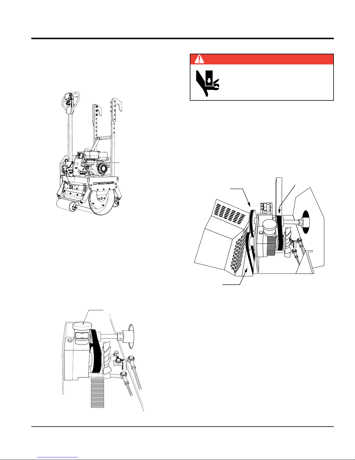
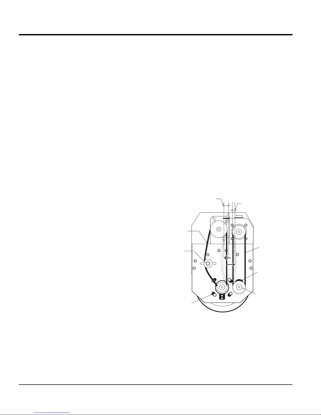
ADJUSTING OR CHANGING TRAVEL V-BELT
1. Unlock the hood retaining latch and lift the hood to
gain access to the V-belts. To adjust the travel V-belt,
loosen the four mounting screws on the reduction
gearbox (Figure 34).
2 TO 2.5 INCHES
(5 TO 6 CM.)
3/4 INCH
(2 CM.)
If the engine RPM speed is too fast or slow, consult the
engine owner's manual on how to adjust the engine speed.
To check the vibrations per minute (vpm) of the roller shaft,
place the bottom of the Vibra-Tak tool (knurled cap) on the
roller drum while the vibrating clutch is engaged. Adjust and
read tool as mentioned above. The vibratory shaft speed
should be 4200 vpm.
AXLE PILLOW BLOCK BEARING (75 HRS)
Lubricate the axle pillow block bearing every 75 hours with
2 shots of EP-3 grease or equivalent.
STABILIZER ROLLS (75 HRS)
Lubricate the stabilizer rolls in 4 places every 75 hours with
2 shots each of EP-3 grease or equivalent.
SCRAPER BLADES (DAILY)
The scraper blades should be cleaned daily after each
use to prevent the build-up of dirt, mud, tar and any other
VIBRATORY
V-BELT
PULLEY
TENSIONER
REDUCTION
GEARBOX
SCREWS
TRAVEL V-BELT
PRY POINT
TO ADJUST
TRAVEL V-BELT
DRIVE
PULLEY
Figure 34. Travel and Vibratory Belts
2. Use the pry point (Figure 34) to achieve correct amount
of V-belt tension. Tighten gearbox screws and check belt
tension by verifying the amount of deflection when the
belt is pressed midway between the two pulleys. This
deflection should be approximately 3/4 of an inch (2 cm.).
PAGE 28 — V305EH VIBRATORY ROLLER • OPERATION AND PARTS MANUAL — REV. #1 (06/21/16)
Page 29
MAINTENANCE
ADJUSTING OR CHANGING VIBRATORY V-BELT
1. To adjust the vibratory V-belt, loosen the pulley
tensioner nut (Figure 34) and adjust the V-belt for
approximately 2 to 2 ½ inches (5 to 6 cm.) of deflection.
2. Check V-belt deflection when V-belt is pressed midway
between the two pulleys.
3. When the correct amount V-belt deflection has been
achieved, retighten pulley tensioner nut.
NOTICE
IMPORTANT! Always adjust the vibratory V-belt to the
recommended belt tension.
A tight V-belt will cause the roller to vibrate even it the
vibration control lever is in the off position.
A loose V-belt will decrease the vibratory action or there
may not be any vibratory action at all.
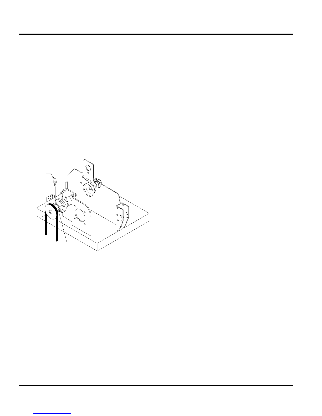
ADJUSTING OR CHANGING HYDROSTATIC PUMP
DRIVE BELT
2. Move the pump unit towards the rear of the roller
and adjust the cogged belt for approximately 1/2 inch
(1.27 cm) deflection when the belt is pressed midway
between the two pulleys.
3. When the correct amount of belt deflection has been
achieved, retighten hydrostatic pump mounting screws.
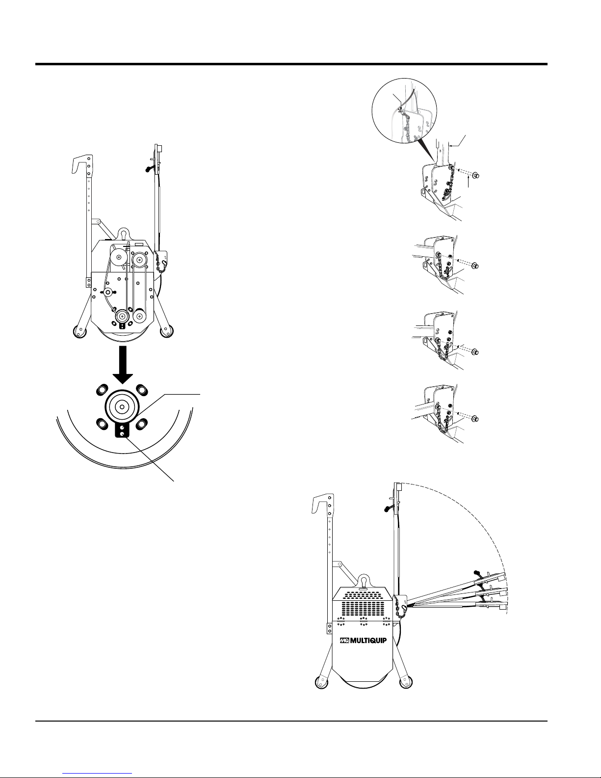
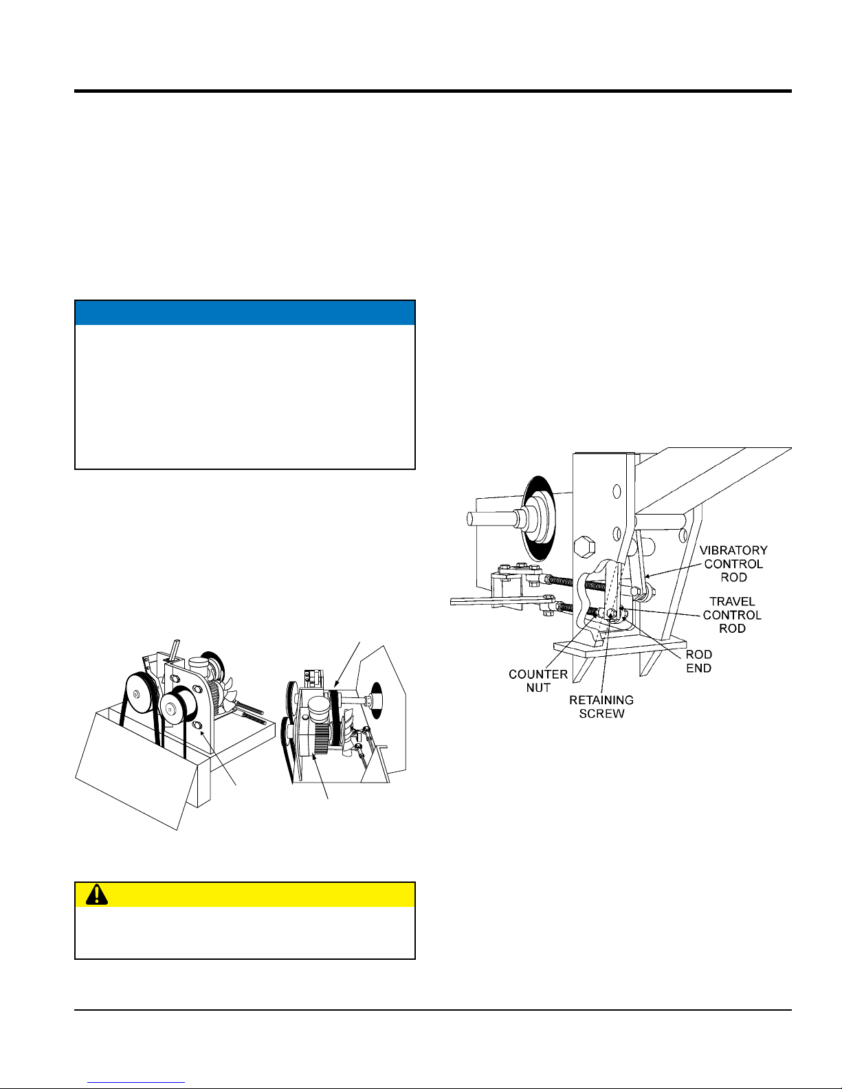
ADJUSTING TRAVEL CONTROL ROD
1. To adjust the travel control rod (controls forward,
reverse and neutral), it will be necessary to start the
engine and run it a low speed.
2. On the travel control rod, loosen the counter nut on
the rod end.
3. Remove retaining screw as shown in Figure 36, then
rotate the rod end to acquire desired length.
1. To change or adjust the cogged drive belt (Figure 35)
for the hydrostatic pump, loosen the four mounting bolts
on the hydrostatic pump.
COGGED
DRIVE BELT
PUMP
MOUNTING
SCREWS
Figure 35. Hydrostatic Pump Drive Belt
HYDROSTATIC
PUMP
CAUTION
Use caution when adjusting control rods, since engine
is running.
Figure 36. Travel Control Rod
4. Adjust travel rod so that its static position (no force
applied on drive control) falls into the neutral position.
The roller should not move once adjustment is
complete.
5. Retighten all hardware.
V305EH VIBRATORY ROLLER • OPERATION AND PARTS MANUAL — REV. #1 (06/21/16) — PAGE 29
Page 30
(A
MAINTENANCE
ADJUSTING VIBRATORY CONTROL ROD
1. To adjust the vibratory control rod (controls vibration),
loosen the counter nut on the rod end of the vibratory
control rod.
2. Remove the retaining screw on the rod end and rotate
the rod to achieve the desired rod length.
3. Continue adjusting, until clutch operation is adequate.
The V-belt for the vibratory action should not move
when the control lever is in the OFF position. Once
adjustment is complete, retighten all hardware.
CLUTCH LUBRICATION
Lubricate the clutch as shown in Figure 37.
ZERK
FITTING
ROLLER STORAGE
For storage of the roller for over 30 days, the following is
recommended:
Drain the fuel tank completely.
Run the engine until the fuel in the injection system is
completely consumed.
Completely drain used oil from the engine crankcase
and fill with fresh clean oil, then follow the procedures
described in the engine manual for engine storage.
Drain water tank.
Clean the entire roller and engine compartment.
Remove battery and store it in cool dry place.
Place roller control handle in the upright position
(vertical).
Cover the roller and place it a clean dry area, that is
protected from harsh elements.
LUBRICATE CLUTCH WITH
EP-3 GREASE .33 OZ.
SHOT EVERY 50 HOURS)
Figure 37. Lubrication Points (Zerk Fittings)
Remove ignition key, and store in a safe place.
PAGE 30 — V305EH VIBRATORY ROLLER • OPERATION AND PARTS MANUAL — REV. #1 (06/21/16)
Page 31

TROUBLESHOOTING
Troubleshooting - Roller
SYMPTOM POSSIBLE PROBLEM SOLUTION
Damaged rubber coupling and flange? Replace urethane coupling and flange.
Defective travel cable and link? Repair or replace travel cable and link.
Unit does not travel or
travel is not smooth.
Unit does not vibrate
or has weak vibration.
Damaged scraper or too much mud in
scraper?
Low oil level? Replenish or replace oil.
Damaged hydraulic pump? Replace hydraulic pump.
Damaged drum gear reduced? Repair.
Bad drum bearings? Repair or replace.
Defective rubber shock mounts? Replace.
Defective travel V-belt? Replace.
Defective centrifugal clutch? Repair or replace clutch.
Damaged or slipping V-belt? Replace V-belt or adjust tension.
Damaged vibration cable and linkage? Replace or repair vibration cable and linkage.
Defective clutch vibrator pulley V-belt? Replace V-belt.
Replace or repair scraper.
V305EH VIBRATORY ROLLER • OPERATION AND PARTS MANUAL — REV. #1 (06/21/16) — PAGE 31
Page 32

Symptom Possible Problem Solution
Diffi cult to start, fuel is available, but no spark at
spark plug.
Diffi cult to start, fuel is available, and spark is
present at the spark plug.
Diffi cult to start, fuel is available, spark is
present and compression is normal.
Diffi cult to start, fuel is available, spark is
present and compression is low.
No fuel present at carburetor.
TROUBLESHOOTING
Troubleshooting (Engine)
Spark plug bridging? Check gap, insulation or replace spark plug.
Carbon deposit on spark plug? Clean or replace spark plug.
Short circuit due to defi cient spark plug
insulation?
Improper spark plug gap? Set to proper gap.
Spark plug is red? Check transistor ignition unit.
Spark plug is bluish white?
No spark present at tip of spark plug?
No oil? Add oil as required.
Oil pressure alarm lamp blinks upon starting? (if
applicable)
ON/OFF switch is shorted? Check switch wiring, replace switch.
Ignition coil defective? Replace ignition coil.
Improper spark gap, points dirty? Set correct spark gap and clean points.
Condenser insulation worn or short circuiting? Replace condenser.
Spark plug wire broken or short circuiting? Replace defective spark plug wiring.
Wrong fuel type?
Water or dust in fuel system? Flush fuel system.
Air cleaner dirty? Clean or replace air cleaner.
Choke open? Close choke.
Suction/exhaust valve stuck or protruded? Reseat valves.
Piston ring and/or cylinder worn? Replace piston rings and/or piston.
Cylinder head and/or spark plug not tightened
properly?
Head gasket and/or spark plug gasket damaged? Replace head and spark plug gaskets.
No fuel in fuel tank? Fill with correct type of fuel.
Fuel cock does not open properly?
Fuel fi lter/lines clogged? Replace fuel fi lter.
Fuel tank cap breather hole clogged? Clean or replace fuel tank cap.
Air in fuel line? Bleed fuel line.
Check spark plug insulation, replace if worn.
If insuffi cient compression, repair or replace
engine. If injected air leaking, correct leak. If
carburetor jets clogged, clean carburetor.
Check transistor ignition unit is broken, and
replace defective unit. Check if voltage cord
cracked or broken and replace. Check if spark
plug if fouled and replace.
Check automatic shutdown circuit, "oil sensor".
(if applicable)
Flush fuel system, replace with correct type of
fuel.
Torque cylinder head bolts and spark plug.
Apply lubricant to loosen fuel cock lever,
replace if necessary.
PAGE 32 — V305EH VIBRATORY ROLLER • OPERATION AND PARTS MANUAL — REV. #1 (06/21/16)
Page 33

Symptom Possible Problem Solution
Weak in power, compression is proper and
does not misfi re.
Weak in power, compression is proper but
misfi res.
Engine overheats
Rotational speed fl uctuates.
Recoil starter malfunctions. (if applicable)
Starter malfunctions.
Burns too much fuel.
Exhaust color is continuously "white".
Exhaust color is continuously "black".
Will not start, no power with key "ON". (if
applicable)
TROUBLESHOOTING
Troubleshooting (Engine) - continued
Air cleaner dirty? Clean or replace air cleaner.
Improper level in carburetor? Check fl oat adjustment, rebuild carburetor.
Defective spark plug? Clean or replace spark plug.
Improper spark plug? Set to proper gap.
Water in fuel system?
Dirty spark plug? Clean or replace spark plug.
Ignition coil defective? Replace ignition coil.
Wrong type of fuel? Replace with correct type of fuel.
Cooling fi ns dirty? Clean cooling fi ns.
Intake air restricted?
Oil level too low or too high? Adjust oil to proper level.
Governor adjusted incorrectly? Adjust governor.
Governor spring defective? Replace governor spring.
Fuel fl ow restricted? Check entire fuel system for leaks or clogs.
Recoil mechanism clogged with dust and dirt? Clean recoil assembly with soap and water.
Spiral spring loose? Replace spiral spring.
Loose, damaged wiring?
Battery insuffi ciently charged? Recharge or replace battery.
Starter damaged or internally shorted? Replace starter.
Over-accumulation of exhaust products?
Wrong spark plug?
Lubricating oil is wrong viscosity? Replace lubricating oil with correct viscosity.
Worn rings? Replace rings.
Air cleaner clogged? Clean or replace air cleaner.
Choke valve set to incorrect position? Adjust choke valve to correct position.
Carburetor defective, seal on carburetor
broken?
Poor carburetor adjustment, engine runs too
rich?
ON/OFF device not activated ON? Turn on ON/OFF device.
Battery disconnected or discharged?
Ignition switch/wiring defective? Replace ignition switch. Check wiring.
Flush fuel system and replace with correct
type of fuel.
Clear intake of dirt and debris. Replace air
cleaner elements as necessary.
Ensure tight, clean connections on battery
and starter.
Check and clean valves. Check muffl er and
replace if necessary.
Replace spark plug with manufacturer's
suggested type.
Replace carburetor or seal.
Adjust carburetor.
Check cable connections. Charge or replace
battery
V305EH VIBRATORY ROLLER • OPERATION AND PARTS MANUAL — REV. #1 (06/21/16) — PAGE 33
Page 34

EXPLANATION OF CODE IN REMARKS COLUMN
The following section explains the different symbols and
remarks used in the Parts section of this manual. Use the
help numbers found on the back page of the manual if there
are any questions.
SAMPLE PARTS LIST
NO.
1 12345 BOLT
2% WASHER, 1/4 IN.
2% 12347 WASHER, 3/8 IN.
3 12348 HOSE
4 12349 BEARING
NO. Column
PART NO. Column
QTY. Column
— Item quantity can be indicated by a
A/R (As Required) is generally used for hoses or other
A blank entry generally indicates that the item is not sold
separately. Other entries will be clarifi ed in the “Remarks”
Some of the most common notes found in the “Remarks”
Column are listed below. Other additional notes needed
— All items on the parts list with the
same unique symbol will be included when this item is
— Used to list an effective serial
— Indicates that the part
is used only with the specifi c model number or model
number variant listed. It can also be used to show a
part is NOT used on a specifi c model or model number
— Indicates that the part can
be purchased at any hardware shop or made out of
available items. Examples include battery cables, shims,
— Indicates that an item cannot
be purchased as a separate item and is either part of an
assembly/kit that can be purchased, or is not available
Numbers Used
number, a blank entry, or A/R.
NOTICE
The contents and part numbers listed in the parts
section are subject to change without notice. Multiquip
does not guarantee the availability of the parts listed.
PART NO. PART NAME QTY. REMARKS
.....................1 .....INCLUDES ITEMS W/%
..........NOT SOLD SEPARATELY
..1 .....MQ-45T ONLY
..................A/R ...MAKE LOCALLY
..............1 .....S/N 2345B AND ABOVE
Unique Symbols — All items with same unique symbol
(@, #, +, %, or >) in the number column belong to the
same assembly or kit, which is indicated by a note in the
“Remarks” column.
Duplicate Item Numbers — Duplicate numbers indicate
multiple part numbers, which are in effect for the same
general item, such as different size saw blade guards in
use or a part that has been updated on newer versions
of the same machine.
parts that are sold in bulk and cut to length.
Column.
REMARKS Column
to describe the item can also be shown.
Assembly/Kit
purchased.
Indicated by:
“INCLUDES ITEMS W/(unique symbol)”
Serial Number Break
number range where a particular part is used.
Indicated by:
“S/N XXXXX AND BELOW”
“S/N XXXX AND ABOVE”
“S/N XXXX TO S/N XXX”
NOTICE
When ordering a part that has more than one item
number listed, check the remarks column for help in
determining the proper part to order.
Numbers Used — Part numbers can be indicated by a
number, a blank entry, or TBD.
TBD (To Be Determined) is generally used to show a
part that has not been assigned a formal part number
at the time of publication.
A blank entry generally indicates that the item is not sold
separately or is not sold by Multiquip. Other entries will
be clarifi ed in the “Remarks” Column.
PAGE 34 — V305EH VIBRATORY ROLLER • OPERATION AND PARTS MANUAL — REV. #1 (06/21/16)
Specifi c Model Number Use
variant.
Indicated by:
“XXXXX ONLY”
“NOT USED ON XXXX”
“Make/Obtain Locally”
and certain washers and nuts.
“Not Sold Separately”
for sale through Multiquip.
Page 35

SUGGESTED SPARE PARTS
V305EH WALK-BEHIND ROLLER
1 to 3 units
Qty. P/N Description
3............EM491116 ............ V-BELT TRAVEL
3............EM504233 ............ V-BELT VIBRATORY
3............EM491132 ............ DRIVE BELT, COGGED PUMP
15..........EM504441 ............ MOUNT, SHOCK
3............800806 ..................LATCH
1............803895 ..................CLUTCH ASSY.
1............42435 ....................WATER TANK CAP
1............800796 ..................WATER FILTER
NOTICE
Part numbers on this Suggested Spare Parts list may
supersede/replace the part numbers shown in the
following parts lists.
GX340UT2QAE2 GASOLINE ENGINES
1 to 3 units
Qty. P/N Description
1............17620Z4H030 ....... CAP FUEL TANK
1............17672Z4H000 ....... FILTER FUEL
3............9807955846 ..........SPARK PLUG
1............35480ZF6003 ....... SWITCH ASSY., OIL ALERT
2............28462ZV7003 ....... ROPE, RECOIL
3............17210ZE3010 ....... ELEMENT AIR CLEANER
5............9820030500 .........FUSE, BLADE (5A)
1............35111880013 .......IGNITION KEY
V305EH VIBRATORY ROLLER • OPERATION AND PARTS MANUAL — REV. #1 (06/21/16) — PAGE 35
Page 36

9
6
14
11
13
5
3
9
9
15
10
8
9
1
2
4
7
12
QUALITY
MANAGEMENT SYSTEM
CERTIFIED ON
ISO 9001:2008
518524
High RPM: RPM
Low RPM: RPM
WATER
TANK
CIP948438
511724
511724
IMPORTANT
HYDRAULIC OIL LEVEL HOT
HYDRAULIC OIL LEVEL COLD
1
6
2
3
4
5
(7X)
CIP 804294
No.
1 CIP803896
2 CIP803900
3 CIP803898
4 CIP803901
5 CIP803897
6 CIP803895
1
1
1
1
7
1
P/N DESCRIPTION QUANTITY
MAINTENANCE
INSTRUCTIONS:
SERVICING EVERY
100 HOURS OF OPERATION
(SEE OWNER’S MANUAL)
GREASE DAILY
(USE GREASE
HIGH TEMPERATURE
EP3 NLGI GRADE 3)
PULLEY ASSEMBLY
SLIDING DISC
PIN
CAM SLEEVE
BALL 7/16”
CLUTCH
10
CIP511768
Hydraulic Oil
Shell Telus 32
CHECK LEVEL EVERY 50 HOURS
511724
CIP492003
Fuel
COMBUSTIBLE
CAUTION
HOT MUFFLER CAN
BURN YOU.
Stay away if engine
has been running.
MODEL
SERIAILNO.
SAFETY
INSTRUCTIONS
1. Read owner’s manual
before operating.
2. Keep unauthorized and untrained
people away from machine during
operation.
3. Make sure all safety devices are in
place before this machine is started.
4. Make sure engine is turned off and
spark plug wire is disconnected before
cleaning the machine.
5. Keep hands and fingers away from
moving objects.
6. Do not operate machine in an enclosed
area, proper ventilation is required.
7. Never leave machine unattended when
operating.
8. Always stop engine and allow engine
to cool before adding fuel or oil.
CIP520935
To avoid injury
you MUST read
and understand
operator’s manual
before using this
machine.
This machine to
be operated by
qualified
personnel only.
Ask for training
as needed.
P/N35137
WARNING
CLOSE
CERRADO
OPEN
ABIERTO
PUSH
RELEASE
EMPUJE
VIBRATION
VIBRACION
FORWARD
PUSH
TO STOP
AVANCE
EMPUJE
PARA PARAR
REVERSE
N
REVERSA
VIBRATION
STOP
PARO
VIBRACION
804100
LIBERAR
PARA
TO
SPRINKLER
ROCIADOR
MULTIQUIP COMPANY, 18910 WILMINGTON AVENUE
CARSON, CALIFORNIA 90746
310-537-3700, 800/421-1244 NATIONWIDE, FAX: 310-537-3927
PUSH
EMPUJAR
511724
CAUTION!
ATTACH SAFETY CHAIN
DURING TRANSPORT
16
NAMEPLATE AND DECALS ASSY.
PAGE 36 — V305EH VIBRATORY ROLLER • OPERATION AND PARTS MANUAL — REV. #1 (06/21/16)
Page 37

NAMEPLATE AND DECALS ASSY.
NO. PART NO. PART NAME QTY. REMARKS
1 804294 DECAL: ATTENTION, GREASE DAILY 1
2 35137 DECAL: WARNING, READ MANUAL 1
3 804100 DECAL: CONTROL 1
4 492003 DECAL: FUEL COMBUSTIBLE 1
5 DECAL: CAUTION, HOT MUFFLER ..................1................INCLUDED W/ENGINE
6 513580 DECAL: ENGINE RPM 1
7 DECAL: CAUTION, ATTACH SAFETY CHAIN ..1................INCLUDED W/ENGINE
8 518524 DECAL: QUALITY MANAGEMENT ISO 1
9 511724 DECAL: GREASE EVERY 75 HOURS 1
10 510892 DECAL: MQ LOGO 2
11 13118 DECAL: POWDER COATED 1
12 948438 DECAL: WATER TANK 1
13 SERIAL PLATE ..................................................1................CONTACT MQ PARTS DEPT.
14 520935 DECAL: SAFETY INSTRUCTIONS 1
15 511768 DECAL: HYD. OIL CHECK EVERY 50 HRS. 1
16 491757 RIVET 2
V305EH VIBRATORY ROLLER • OPERATION AND PARTS MANUAL — REV. #1 (06/21/16) — PAGE 37
Page 38

IMPORTANT
HYDRAULIC OIL LEVEL HOT
HYDRAULIC OIL LEVEL COLD
20
CLUTCH ROD ASSY.
B
A
10
30
520
490
490
80
480
470
A
460
470
40
500
230
510
170
B
140
190
240
70
210
180
190
120
1
110
160
200
PAGE 38 — V305EH VIBRATORY ROLLER • OPERATION AND PARTS MANUAL — REV. #1 (06/21/16)
NOTES:
SEE VIBRATORY ROD ASSY.
1
Page 39

CLUTCH ROD ASSY.
NO. PART NO. PART NAME QTY. REMARKS
10 803895 CLUTCH ASSEMBLY 1
20 EM963610 CAP SCREW .....................................................1................REPLACES P/N 492375
30 500169 KEY SQUARE 3/16"X2" 1
40 EM504233 V-BELT, VIBRATORY DRIVE 1
70 0166 A WASHER, LOCK 3/8" ........................................1................REPLACES P/N 492624
80 520957 WASHER, FLAT 3/8" 1
110 800283 ROD, CLUTCH, NO. 1 1
120 490172 NUT HEX, 3/8" G5 3
140 EM969013 NUT NYLOC ......................................................2................REPLACES P/N 492583
160 520241 RETAINER 2
170 519567 PIVOT BRACKET 1
180 503738 BEARING 1
190 EM963057 BOLT 3/8" ...........................................................3................REPLACES P/N 492313
200 EM503115 SCREW ..............................................................2................REPLACES P/N 503115
210 503119 NUT LOCK 2
230 800284 ROD, CLUTCH, NO. 2 1
240 520240 SPACER 1
460 1066235708 SCREW GUIDE .................................................2................REPLACES P/N 502643
470 0202 SCREW HHC 5/16X18X1 ..................................4................REPLACES P/N 492364
480 EM923023 WASHER, FLAT 5/16" ........................................1................REPLACES P/N 492597
490 2105164 NUT NYLON 5/16-18 .........................................4................REPLACES P/N 492582
500 512067 CLEVIS, CLUTCH 1
510 492303 BOLT 5/16" NC X 1-1/4" .....................................1................REPLACES P/N 492365
520 3019092 WASHER 3/8" ....................................................1................REPLACES P/N 508346
V305EH VIBRATORY ROLLER • OPERATION AND PARTS MANUAL — REV. #1 (06/21/16) — PAGE 39
Page 40

580
VIBRATORY ROD ASSY.
400
600
620
590
LEFT
260
610
A
250
570
A
B
RIGHT
620
600
340
10
320
190
270
300
330
60
310
480
280
500
490
FRAME
290
220
210
B
190
200
370
250
1
230
390
190
380
NOTES:
SEE CLUTCH ROD ASSY.
1
PAGE 40 — V305EH VIBRATORY ROLLER • OPERATION AND PARTS MANUAL — REV. #1 (06/21/16)
Page 41

VIBRATORY ROD ASSY.
NO. PART NO. PART NAME QTY. REMARKS
10 804124 HANDLE BAR 1
60 503119 NUT, LOCK 4
190 EM490172 NUT, HEX 3/8" 5
200 511875 FORK LONG GALVANIZED CONTROL 2
210 511898C GALVANIZED FORK PIN 2
220 509157 COTTER PIN 2
230 520243 BRACKET, LEFT SIDE 1
250 492584 LOCK NUT 1/2" G5 3
260 EM963102 BOLT 1/2"X1-1/4" G5 .........................................2................REPLACES P/N 492393
270 491019C PLASTIC KNOB, BLACK 1
280 505279 LEVER, VIBRATION 1
290 492379 SCREW, CAP 3/8"X2" G5 1
300 EM969013 NUT, NYLOK 3/8" G8 .........................................1................REPLACES P/N 492583
310 EM492358 BOLT 1/4" NC X 1-1/4" G5 .................................1................REPLACES P/N 492358
320 492581 NUT, NYLON LOCKNUT 1/4"-20 G8 1
330 511874 FORK SHORT GALVANIZED CONTROL 1
340 804134 ROD, VIBRATION 1
370 EM963610 BOLT 3/8" ...........................................................2................REPLACES P/N 492376
380 EM969013 NUT, NYLOC 3/8" NC G8 ..................................2................REPLACES P/N 492583
390 EM959080 ROD, END ..........................................................2................REPLACES P/N 959080
400 519795 RED PUSH BUTTON, CONTACT 1
480 492467 SCREW, ALLEN 5/16"X3/8" 1
490 521090 FLANGE BRACKET PUSH BUTTON 1
500 503118 BOLT 3/16"X1" G2 2
570 804253G LOCK PIN 1
580 925191 PIN HAIR 3/16" 1
590 801594 CHAIN, LINK 3/16"X0.25M 1
600 492581 NUT, NYLON LOCKNUT 1/4"-20 G8 2
610 492357 BOLT 1/4"X1" G5 2
620 509161 WASHER, FLAT 5/16" 2
V305EH VIBRATORY ROLLER • OPERATION AND PARTS MANUAL — REV. #1 (06/21/16) — PAGE 41
Page 42

IMPORTANT
HYDRAULIC OIL LEVEL HOT
HYDRAULIC OIL LEVEL COLD
LEFT
TRANSMISSION ROD ASSY.
60
110
80
90
A
RIGHT
B
100
90
50
40
80
70
140
D
20
30
120
530
560
380
C
240
190
390
350
370
200
360
190
210
B
540
550
D
180
170
160
130
150
HYDROSTATIC
PUMP
220
15
11
16
A
12
13
17
18
14
C
10
PAGE 42 — V305EH VIBRATORY ROLLER • OPERATION AND PARTS MANUAL — REV. #1 (06/21/16)
Page 43

TRANSMISSION ROD ASSY.
NO. PART NO. PART NAME QTY. REMARKS
10 804143 ROD, TRANSMISSION 1
11 EM963057 BOLT 3/8" ...........................................................1................REPLACES P/N 492313
12 EM959080 ROD, END ..........................................................1................REPLACES P/N 959080
13 EM490172 NUT, HEX 3/8"-24 1
14 EM969013 NUT, NYLOC 3/8"NC G8 ...................................1................REPLACES P/N 492583
15 804144 LEVER, TRANSMISSION 1
16 491759 KEY, WOODRUFF 1/8" X 1/2" 1
17 0166 A WASHER, LOCK 3/8" ........................................1................REPLACES P/N 492624
18 EM969012 NUT, LOCK 3/8" .................................................1................REPLACES P/N 505066
20 520252 HANDLE, CONTROL 1
30 504564 GRIP, HANDLE 2
40 EM503115 SCREW 3/16"NC X 3/4" G2 ...............................2................REPLACES P/N 503115
50 520241 RETAINER 2
60 503119 NUT, LOCK 3/16"NC G8 4
70 492378 SCREW 3/8"NC X 1-3/4" G5 1
80 3019092 WASHER, FLAT 3/8" ..........................................2................REPLACES P/N 492598
90 520240 ALUMINUM SPACER BUSHING 2
100 503738 BEARING 1
110 EM969013 NUT, NYLOK 3/8"NC G8....................................1................REPLACES P/N 492583
120 EM963057 BOLT 3/8" ...........................................................1................REPLACES P/N 492313
130 EM959080 ROD END ..........................................................1................REPLACES P/N 959080
140 EM969013 NUT, NYLOC 3/8"NC G8 ...................................1................REPLACES P/N 492583
150 804135 ADVANCE ROD 1
160 EM491686 PIN, COTTER ....................................................2................REPLACES P/N 491686
170 504679 WASHER, FLAT 3/8" 4
180 EM503744 SPRING 2
190 EM490172 NUT, HEX 3/8" 5
200 511875 FORK LONG GALVANIZED CONTROL 2
240 503111 SCREW, HHC 1/2-13X4-1/2" 1
350 520242 BRACKET, RIGHT SIDE 1
360 511870C BUSHING 1
370 EM963610 BOLT 3/8" ...........................................................2................REPLACES P/N 492376
380 EM969013 NUT, NYLOC 3/8" G8.........................................2................REPLACES P/N 492583
390 EM959080 ROD END .........................................................2................REPLACES P/N 959080
530 804131TT LEVER, WATER RETAINER 1
540 804130 SPRING, RATCHET LEVER 1
550 492581 NUT, NYLON LOCKNUT 1/4"-20 G8 1
560 EM963007 CAP SCREW 1/4" NC X 1-1/2" G5 ....................1................REPLACES P/N EM492359
V305EH VIBRATORY ROLLER • OPERATION AND PARTS MANUAL — REV. #1 (06/21/16) — PAGE 43
Page 44

A
440
450
PUMP/FAN ASSY.
470
460
470
240
230
250
260
220
90
A
210
290
100
270
280
430
300
480
TO ENGINE
DRIVE SHAFT
310
130
650
170
160
140
180
190
150
80
50
60
490
40
30
20
70
PAGE 44 — V305EH VIBRATORY ROLLER • OPERATION AND PARTS MANUAL — REV. #1 (06/21/16)
120
110
10
Page 45

PUMP/FAN ASSY.
NO. PART NO. PART NAME QTY. REMARKS
10 EM510971 PUMP, HYDROSTATIC 1
20 492363 BOLT, 5/16" NC X 3/4" G5 1
30 EM923343 WASHER, LOCK 5/16" ......................................1................REPLACES P/N 492623
40 100536 WASHER, BRAKE 2
50 491759 KEY WOODRUFF 1/8"X1/2 1
60 EM490300 PULLEY, TRAVEL 1
70 EM491116 V-BELT, DRIVE 1
80 490166 BOLT, HEX 3/8"X3-1/2" 4
90 504679 WASHER, FLAT 3/8" 4
100 EM969013 NUT NYLOK ......................................................4................REPLACES P/N 492583
110 491759 KEY WOODRUFF 1/8"X1/2" 1
120 491033 PULLEY, DRIVE BELT 1
130 503110 SCREW SET 1
140 502651 SPACER FAN 1
150 EM493150 FAN 1
160 EM502650 WASHER, FAN SECURING 1
170 3103160 WASHER, LOCK 3/16" ......................................2................REPLACES P/N 492621
180 EM963007 CAP, SCREW ....................................................1................REPLACES P/N EM492359
190 2101402 WASHER, LOCK 1/4" ........................................1................REPLACES P/N 492622
210 490984 SNAP RING 2
220 492179 BEARING SHAFT PIN 2
230 EM502629 BEARING SUPPORT 1
240 492303 BOLT 5/16" NC X 1-1/4" .....................................6................REPLACES P/N 492365
250 EM923023 WASHER, FLAT 5/16" ........................................6................REPLACES P/N 492597
260 2105164 NUT NYLON 5/16-18" ........................................6................REPLACES P/N 492582
270 EM491032 GEAR WHEEL 1
280 EM491132 BELT, ENGINE TO PUMP DRIVE 1
290 492468 SCREW SET 5/16" 2
300 500194 KEY SQUARE 1
310 802442 COLLAR, LOCKING 1
430 511891 CLEVIS 1
440 EM511890 LEVER PUMP OVERRIDE 1
450 0202 SCREW HHC 5/16X18X1 ..................................1................REPLACES P/N 492364
460 EM923023 WASHER, FLAT 5/16 .........................................1................REPLACES P/N 492597
470 2105164 NUT NYLON 5/16-18 .........................................2................REPLACES P/N 492582
480 492303 BOLT 5/16" NC X 1-1/4" .....................................1................REPLACES P/N 492365
490 492466 SET SCREW 1/4" NC X 1/2 2
V305EH VIBRATORY ROLLER • OPERATION AND PARTS MANUAL — REV. #1 (06/21/16) — PAGE 45
Page 46

500
CABINET ASSY.
410
400
530
510
360
350
340
520
330
420
380
390
640
610
590
630
370
600
580580
620
570
560
340
PAGE 46 — V305EH VIBRATORY ROLLER • OPERATION AND PARTS MANUAL — REV. #1 (06/21/16)
320
330
350
Page 47

CABINET ASSY.
NO. PART NO. PART NAME QTY. REMARKS
320 519637 COVER, BELT 1
330 EM923023 WASHER, FLAT 5/16" ........................................4................REPLACES P/N 492597
340 EM923343 WASHER, LOCK 5/16" ......................................4................REPLACES P/N 492623
350 492363 BOLT 5/16" DIA. NC X3/4" G5 4
360 800487 COVER, COMPARTMENT 1
370 1579 SCREW HHC 1/4-20X1/2" ................................18...............REPLACES P/N 492355
380 EM503740 HINGE ................................................................3................REPLACES P/N 503740
390 492581 NUT 1/4"-20 NYLON LOCKNUT 18
400 800806 LATCH 1
410 514540 RIVET 2
420 490202 RUBBER PROTECTOR/BUMPER 2
500 23297 MANUAL HOLDER 1
510 EM923057 WASHER 1/4" ....................................................3................REPLACES P/N 492596
520 492581 NUT 1/4"-20 NYLON LOCKNUT 3
530 492356 BOLT 1/4"X3/4" 3
560 492379 SCREW, CAP 3/8" 1
570 0166 A WASHER, LOCK 3/8" ........................................1................REPLACES P/N 492624
580 513979C SPACER/BUSHING 1
590 800810 TIE ROD 1
600 3019092 WASHER, FLAT 3/8" ..........................................1................REPLACES P/N 492598
610 EM969013 NUT NYLOK ......................................................1................REPLACES P/N 492583
620 EM963610 CAP, SCREW ....................................................1................REPLACES P/N 492375
630 3019092 WASHER, FLAT 3/8" ..........................................1................REPLACES P/N 492598
640 1456 NUT, HEX 3/8" ...................................................1................REPLACES P/N 492554
V305EH VIBRATORY ROLLER • OPERATION AND PARTS MANUAL — REV. #1 (06/21/16) — PAGE 47
Page 48

SIDE COVER
320
WATER TANK ASSY.
340
70
60
40
A
40
10
310
350
30
160
150
240
70
290
180
280
250
70
330
300
240
110
260
360
270
130
40
100
80
90
50
PAGE 48 — V305EH VIBRATORY ROLLER • OPERATION AND PARTS MANUAL — REV. #1 (06/21/16)
20
200
190
20
230
60
70
220
A
40
140
170
130
80
120
40
Page 49

WATER TANK ASSY.
NO. PART NO. PART NAME QTY. REMARKS
10 519545 PLASTIC TANK, WATER 1
20 800390 FRONT BRACKET, WATER TANK 2
30 42435 WATER TANK CAP 1
40 506071 ELBOW PVC 5
50 800387 HOSE, TANK 1
60 505389 CLAMP, 3/4" 4
70 EM923057 WASHER, FLAT 1/4" ..........................................8................REPLACES P/N 492596
80 2101402 WASHER, LOCK 1/4" ........................................4................REPLACES P/N 492622
90 492356 BOLT 1/4" X 3/4" G5 2
100 800380 HOSE, TANK VALVE 1
110 520268 VALVE, WATER 1
120 2508 SCREW HHC 1/4-20X2-1/4 ...............................2................REPLACES P/N 512414
130 492467 SCREW ALLEN 5/16" 4
140 800394 PIVOT SHAFT 1
150 EM923023 WASHER, FLAT 5/16" ........................................1................REPLACES P/N 492597
160 2105164 NUT NYLON 5/16"-18 ........................................1................REPLACES P/N 492582
170 492468 SCREW SET 5/16" 1
180 800379 SUPPORT, TANK VALVE 1
190 EM963692 BOLT 1/2"UNC X1-1/2" ......................................4................REPLACES P/N 492394
200 6109180 WASHER, LOCK 1/2" ........................................4................REPLACES P/N 492626
220 520275 SPRAYER 1
230 492356 BOLT 1/4" X 3/4" G5 2
240 492581 NUT 1/4"-20 NYLON LOCKNUT 4
250 804142 CABLE, WATER 1
260 520183 BUSHING 1
270 516487 END ROD 1
280 804140TT LEVER, WATER 1
290 491019 KNOB, BLACK PLASTIC 1
300 800371 BUSHING FOR LEVER 1
310 3019092 WASHER FLAT 3/8" ...........................................1................REPLACES P/N 492598
320 492378 BOLT 3/8"X1-3/4" G5 1
330 800398 SPRING, VALVE 1
340 800399 SPRING, HANDLE 1
350 EM916019 FITTING, GREASE ............................................1................REPLACES P/N 491705
360 800796 WATER FILTER 1
V305EH VIBRATORY ROLLER • OPERATION AND PARTS MANUAL — REV. #1 (06/21/16) — PAGE 49
Page 50

ROLLER ASSY.
490
480
260
460
250
440
450
430
320
270
420
230
400
240
410
300
310
290
220
280
390
140
340
280
210
150
140
10
200
30
50
120
100
60
A
110
B
90
A
100
90
80
110
70
50
30
40
380
370
20
120
130
350
140
40
190
140
180
170
160
150
PAGE 50 — V305EH VIBRATORY ROLLER • OPERATION AND PARTS MANUAL — REV. #1 (06/21/16)
B
Page 51

ROLLER ASSY.
NO. PART NO. PART NAME QTY. REMARKS
10 804210 ROLLER .............................................................1................S/N 160400 AND BELOW
10 521685 ROLLER .............................................................1................S/N 160401 AND ABOVE
20 519659 SHAFT, VIBRATOR ............................................1................S/N 160400 AND BELOW
20 804694 SHAFT, VIBRATOR ............................................1................S/N 160401 AND ABOVE
30 519661 SEAL, OIL ..........................................................2................S/N 160400 AND BELOW
30 513286 SEAL, OIL ..........................................................2................S/N 160401 AND ABOVE
40 EM490985 RING RETAINING .............................................2................S/N 160400 AND BELOW
40 506135 RING RETAINING .............................................2................S/N 160401 AND ABOVE
50 EM492160 BEARING ...........................................................2................S/N 160400 AND BELOW
50 506131 BEARING ...........................................................2................S/N 160401 AND ABOVE
60 804209 HOUSING, RIGHT SIDE ....................................1................S/N 160400 AND BELOW
60 804669 HOUSING, RIGHT SIDE ....................................1................S/N 160401 AND ABOVE
70 804208 HOUSING, LEFT SIDE ......................................1................S/N 160400 AND BELOW
70 804670 HOUSING, LEFT SIDE ......................................1................S/N 160401 AND ABOVE
80 EM511777 OIL SEAL 39X52X10 .........................................1................S/N 160400 AND BELOW
80 506144 OIL SEAL ...........................................................1................S/N 160401 AND ABOVE
90 EM492299 HEX BOLT 5/16"X1/2" 4
100 519337 WASHER, FLAT 1/2" 12
110 EM492455 BOLT HX HD 1/2"X1-1/2" ..................................12...............REPLACES P/N 492455
120 EM504441 MOUNT SHOCK 10
130 519493 DRIVE SUPPORT PLATE, RIGHT-SIDE 1
140 6109180 WASHER, LOCK 1/2" .......................................23...............REPLACES P/N 492626
150 492584 NUT, LOCK 1/2" NC 10
160 EM492174 PILLOW BLOCK 1
170 800769 ROLLER SUPPORT 1
180 492395 BOLT 1/2"NC X 1-3/4" G5 2
190 981635 BOLT HX HD 1/2"-13 NC X1" ............................3................REPLACES P/N 492392
200 519492 DRIVE SUPPORT PLATE, LEFT-SIDE 1
210 EM500913 DRIVE, GEAR REDUCTION ASSY. 1
220 519651 TOP COVER SUPPORT 1
230 803956 PULLEY 1
240 100536 WASHER, BRAKE 4
250 EM923343 WASHER, LOCK 5/16" ......................................2................REPLACES P/N 492623
260 492363 BOLT 5/16" NC X3/4" G5 2
270 1294220103 SHAFT GOVERNOR .........................................1................REPLACES P/N 502625
280 490300 PULLEY, S-A 1
290 491759 KEY WOODRUFF 1/8"X1/2" 1
300 6109170 WASHER, FLAT 1/2" ..........................................4................REPLACES P/N 504322
V305EH VIBRATORY ROLLER • OPERATION AND PARTS MANUAL — REV. #1 (06/21/16) — PAGE 51
Page 52

ROLLER ASSY. (CONTINUED)
490
260
460
480
450
250
440
430
320
270
420
230
400
240
410
300
310
290
220
280
390
140
340
280
210
150
140
10
200
30
50
120
100
60
A
110
B
90
A
100
90
80
110
70
50
30
40
380
370
20
120
130
350
140
40
190
140
180
170
160
150
PAGE 52 — V305EH VIBRATORY ROLLER • OPERATION AND PARTS MANUAL — REV. #1 (06/21/16)
B
Page 53

ROLLER ASSY. (CONTINUED)
NO. PART NO. PART NAME QTY. REMARKS
310 EM963102 BOLT 1/2"NC X1-1/4" G5 ...................................1................REPLACES P/N 492393
320 492467 SCREW, ALLEN 5/16"NC X3/8" 2
340 492466 SCREW, ALLEN 1/4"NC X1/2" 2
350 504723 NUT 1/2" NC G8 2
370 EM521003 SPACER .............................................................2................S/N 160400 AND BELOW
370 804695 SPACER .............................................................2................S/N 160401 AND ABOVE
380 EM492254 BOLT HX HD 1/4"NC X3/4" G8 6
390 EM504456 BOLT HX HD 1/2-13"X3/4" G8 4
400 EM963692 BOLT 1/2"NC X1-1/2" G5 ...................................3................REPLACES P/N 492394
410 803994S IDLER PULLEY SHAFT, GALVANIZED 1
420 803995S IDLER PULLEY BUSHING, GALVANIZED 1
430 EM502134 PULLEY 1
440 EM490163 BEARING, IDLER PULLEY 1
450 EM490951 RING, SNAP 1
460 EM490981 RING, SNAP 1
480 EM492625 WASHER, LOCK 7/16 1
490 EM492555 NUT, HEX 7/16-14 1
V305EH VIBRATORY ROLLER • OPERATION AND PARTS MANUAL — REV. #1 (06/21/16) — PAGE 53
Page 54

HANGER ASSY.
460
40
30
440
430
470
420
20
520
510
PAGE 54 — V305EH VIBRATORY ROLLER • OPERATION AND PARTS MANUAL — REV. #1 (06/21/16)
Page 55

HANGER ASSY.
NO. PART NO. PART NAME QTY. REMARKS
20 EM505396 CARRYING, HANGER 1
30 EM502677 HOOK, HANGER 2
40 800774 BRACE, TIE ROD 1
420 EM492421 SCREW, HHC 3/4"NC X3-1/2" G5 .....................6................REPLACES P/N 492421
430 492628 WASHER, LOCK 3/4" 6
440 EM968446 NUT HEX 3/4" ....................................................6................REPLACES P/N 492558
460 EM104 BOLT 5/8-11"X2" ................................................1................REPLACES P/N 503982
470 EM969023 NUT LOCK 5/8" .................................................2................REPLACES P/N 492586
510 EM492421 SCREW, HHC 3/4"NCX3-1/2" G5 ......................4................REPLACES P/N 492421
520 EM505069 NUT, CRIMPED 3/4"-10 4
V305EH VIBRATORY ROLLER • OPERATION AND PARTS MANUAL — REV. #1 (06/21/16) — PAGE 55
Page 56

FRONT STABLIZER ROLLER ASSY.
780
850
580
790
840
870
310
320
470
300
290
450
100
60
80
820
810
260
270
880
280
10
330
50
70
590
90
400
120
400
410
600
390
220
350
340
240
130
240
250
PAGE 56 — V305EH VIBRATORY ROLLER • OPERATION AND PARTS MANUAL — REV. #1 (06/21/16)
170
120
180
750
610
150
760
160
210
190
200
140
Page 57

FRONT STABLIZER ROLLER ASSY.
NO. PART NO. PART NAME QTY. REMARKS
10 804155 CHASSIS 1
50 800323 SUPPORT, RIGHT SPRING SCRAPER 1
60 800324 SUPPORT, LEFT SPRING SCRAPER 1
70 520329 UPPER SUPPORT, SCRAPER 1
80 804136 SCRAPPER, RUBBER 1
90 804137 BACK UP PLATE, REAR 1
100 520341 SPRING EXTENSION, SCRAPER 2
120 804139 SUPPORT, STABIL. LFT. REAR/RT. FRONT 1
130 804138 RIGHT SUPPORT, STABILIZER ROLLER 1
140 516312 ROLLER, STABILIZER 1
150 492173 BEARING 1
160 EM969013 NUT NYLOK ......................................................2................REPLACES P/N 492583
170 0166 A WASHER, LOCK 3/8" ........................................2................REPLACES P/N 492624
180 EM963057 BOLT 3/8" ...........................................................2................REPLACES P/N 492313
190 EM923023 SOCKET HEAD .................................................2................REPLACES P/N 506109
200 EM969023 NUT LOCK 5/8" .................................................2................REPLACES P/N 492586
210 804132 SUPPORT, STABILIZER 1
220 EM963057 BOLT 3/8" ...........................................................3................REPLACES P/N 492313
240 3019092 WASHER, FLAT 3/8" ..........................................6................REPLACES P/N 492598
250 EM969013 NUT NYLOK ......................................................3................REPLACES P/N 492583
260 513452 BOLT 3/8"X1-1/4" G5 4
270 3019092 WASHER, FLAT 3/8" ..........................................4................REPLACES P/N 492598
280 EM969013 NUT NYLOC ......................................................4................REPLACES P/N 492583
290 EM963057 BOLT 3/8" ...........................................................2................REPLACES P/N 492313
300 0166 A WASHER, LOCK 3/8" ........................................3................REPLACES P/N 492624
310 3019092 WASHER, FLAT 3/8" ..........................................3................REPLACES P/N 492598
320 EM969013 NUT NYLOK ......................................................3................REPLACES P/N 492583
330 EM104 BOLT 5/8-11X2" .................................................4................REPLACES P/N 503982
340 EM923348 WASHER, LOCK 5/8" ........................................4................REPLACES P/N 492627
350 EM969023 NUT, STOP ........................................................4................REPLACES P/N EM504724
390 EM963057 BOLT 3/8" ...........................................................2................REPLACES P/N 492313
400 3019092 WASHER, FLAT 3/8" ..........................................4................REPLACES P/N 492598
410 EM969013 NUT NYLOC ......................................................2................REPLACES P/N 492583
450 530298 SCREW HEX 5/8" 1
470 EM969023 NUT LOCK 5/8" .................................................2................REPLACES P/N 492586
580 511807 CLAMP, NYLON 5/8" 2
590 492595 WASHER, FLAT 3/16 1
600 EM503115 SCREW ..............................................................1................REPLACES P/N 503115
750 491704 ZERK FITTING 2
760 491008 ZERK FITTING CAP 2
780 503119 NUT, LOCK 1
790 800417 HOSE, FUEL 8.4" ..............................................1................1 PC=1 FT.
810 803479 WATER FILTER, PROTECTION 1
820 800829 BACK PLATE FILTER PROTECTION 1
840 492379 SCREW CAP 3/8" 4
850 EM491028 WRAP CABLE TIE .............................................6................REPLACES P/N 491028
870 503119 NUT LOCK 4
880 512367 SCREW 4
V305EH VIBRATORY ROLLER • OPERATION AND PARTS MANUAL — REV. #1 (06/21/16) — PAGE 57
Page 58

770
REAR STABLIZER ROLLER ASSY.
775
1
330
360
630
370
360
NOTES:
INCLUDED WITH LATCH ASSY.
1
REFERENCE CABINET ASSY.,
ITEM 400.
80
100
260
70
120
690
700
270
280
750
90
370
760
340
350
130
380
740
730
660
PAGE 58 — V305EH VIBRATORY ROLLER • OPERATION AND PARTS MANUAL — REV. #1 (06/21/16)
720
710
140
680
150
Page 59

REAR STABLIZER ROLLER ASSY.
NO. PART NO. PART NAME QTY. REMARKS
70 520329 UPPER SUPPORT, SCRAPER 1
80 804136 SCRAPPER, RUBBER 1
90 804137 BACK-UP PLATE, REAR 1
100 520341 SPRING EXTENSION, SCRAPER 2
120 804139 SUPPORT, STABIL. LFT. REAR/RT. FRONT 1
130 804138 RIGHT SUPPORT, STABILIZER ROLLER 1
140 516312 ROLLER, STABILIZER 1
150 492173 BEARING 1
260 513452 BOLT 3/8"X1-1/4" G5 4
270 3019092 WASHER, FLAT 3/8" ..........................................4................REPLACES P/N 492598
280 EM969013 NUT, NYLOK ......................................................4................REPLACES P/N 492583
330 EM104 BOLT 5/8-11X2" .................................................4................REPLACES P/N 503982
340 EM923348 WASHER, LOCK 5/8" ........................................4................REPLACES P/N 492627
350 504724 NUT 4
360 EM963057 BOLT 3/8" ...........................................................2................REPLACES P/N 492313
370 3019092 WASHER, FLAT 3/8" ..........................................4................REPLACES P/N 492598
380 EM969013 NUT NYLOC ......................................................2................REPLACES P/N 492583
510 EM492421 HHCS 3/4" NC X3-1/2 G5 ..................................4................REPLACES P/N 492421
520 505069 NUT 4
630 800773 GROMMET 1
660 3019092 WASHER, FLAT 3/8" ..........................................6................REPLACES P/N 492598
680 EM969013 NUT NYLOC ......................................................4................REPLACES P/N 492583
690 0166 A WASHER, LOCK 3/8" ........................................4................REPLACES P/N 492624
700 EM963057 BOLT 3/8" ...........................................................4................REPLACES P/N 492313
710 EM923023 SOCKET HEAD .................................................2................REPLACES P/N 506109
720 EM969023 NUT, LOCK 5/8" .................................................2................REPLACES P/N 492586
730 EM963057 BOLT 3/8" ...........................................................6................REPLACES P/N 492313
740 EM969013 NUT, NYLOC ......................................................6................REPLACES P/N 492583
750 491704 ZERK FITTING 2
760 491008 ZERK FITTING CAP 2
770 800803 HOUR/TACHOMETER 1
775 491757 RIVET 2
V305EH VIBRATORY ROLLER • OPERATION AND PARTS MANUAL — REV. #1 (06/21/16) — PAGE 59
Page 60

380
ENGINE COUPLER ASSY.
230
210
220
AUXILIARY VIEW
TO
CLUTCH
1
10
260
270
GND.
260
250
E-STOP
SWITCH
20
280
30
500
490
30
300
480
290
40
NOTES:
INCLUDED WITH ENGINE
1
PAGE 60 — V305EH VIBRATORY ROLLER • OPERATION AND PARTS MANUAL — REV. #1 (06/21/16)
FRAME
Page 61

ENGINE COUPLER ASSY.
NO. PART NO. PART NAME QTY. REMARKS
10 505331 ENGINE, HONDA GX340UT2QAE2 1
20 800771 COUPLING, ENGINE/PUMP 1
30 500194 KEY, SQUARE 2
40 803904 SHAFT, ENGINE DRIVE 1
210 800780 ADAPTER 1
220 800776 DRAIN HOSE 1
230 513619 FITTING 1
250 804146 E-STOP SWITCH WIRE 10 AWG BLACK 1
260 505303 TERMINAL RING, 1/4" BLUE 1
270 505314 PROTECTIVE WIRE COVERING 1
280 521028 SPACER, BUSHING COUPLING 1
290 802442 COLLAR, LOCKING 1
300 EM703 SCREW ALLEN 3/8" ..........................................8................REPLACES P/N 492470
380 804123 STEEL, LANYARD (IGNITION KEY) 1
480 3019092 WASHER, FLAT 3/8" ..........................................4................REPLACES P/N 492598
490 0166 A WASHER, LOCK 3/8" ........................................4................REPLACES P/N 492624
500 EM963057 BOLT 3/8" ...........................................................4................REPLACES P/N 492313
V305EH VIBRATORY ROLLER • OPERATION AND PARTS MANUAL — REV. #1 (06/21/16) — PAGE 61
Page 62

TRANSMISSION ASSY.
PAGE 62 — V305EH VIBRATORY ROLLER • OPERATION AND PARTS MANUAL — REV. #1 (06/21/16)
Page 63

TRANSMISSION ASSY.
NO. PART NO. PART NAME QTY. REMARKS
1# EM502546 TRANSMISSION BASE BOX 1
2# EM502547 TRANSMISSION COVER BOX 1
3# EM491722 SPIRAL PIN 2
4# EM492302 SPECIAL CAP SCREW 9
5# EM492228 BEARING 2
6# EM490990 INTERNAL RETAINING RING 1
7# EM492123 SEAL 1
8# EM490968 EXTERNAL RETAINING RING 1
9# EM503802 GEAR 1
10# EM503803 PIN 2
11# 492451 SPECIAL CAP SCREW 6
12# 0166 A LOCK WASHER, 3/8" 6
13# 3019092 FLAT WASHER, 3/8" 6
14# EM502556 COVER 1
15# EM492122 SEAL 1
16# EM491057 O-RING 1
17# EM492258 HEX SOCKET HEAD BOLT 6
18# EM492229 BEARING 2
19# EM502550 SHAFT 1
20# EM502552 GEAR 1
21# EM502551 KEY 1
22# EM490952 EXTERNAL RETAINING RING 1
23# EM492212 BEARING 2
24# EM502553 SHAFT 1
25# EM502555 COVER 1
26# EM492108 SEAL 1
27# EM491058 O-RING 1
28# EM492254 HEX SOCKET HEAD BOLT 2
29# 2101402 LOCK WASHER, 1/4" 2
30# EM491056 O-RING 2
31# EM492325 CAP SCREW 2
32 EM500913 TRANSMISSION ASSY. .....................................1................INCLUDES ITEM/#
V305EH VIBRATORY ROLLER • OPERATION AND PARTS MANUAL — REV. #1 (06/21/16) — PAGE 63
Page 64

HONDA GX340UT2QAE2 RECOIL STARTER ASSY.
PAGE 64 — V305EH VIBRATORY ROLLER • OPERATION AND PARTS MANUAL — REV. #1 (06/21/16)
Page 65

HONDA GX340UT2QAE2 RECOIL STARTER ASSY.
NO. PART NO. PART NAME QTY. REMARKS
1 28400Z5T003ZA STARTER ASSY., RECOIL, RED ......................1................INCLUDES ITEMS W/#
2# 28410ZE3W01ZP CASE COMP., RECOIL STARTER, RED 1
3# 28421ZE3W01 PULLEY, RECOIL STARTER 1
4# 28422ZE2W01 RATCHET, STARTER 2
5# 28441ZE2W01 SPRING, FRICTION 1
6# 28442ZE2W01 SPRING, STARTER RETURN 1
7# 28443ZE2W01 SPRING, RATCHET 2
8# 28444ZE2W01 RETAINER, SPRING 1
10# 28462ZV7003 ROPE, RECOIL STARTER ...............................1................REPLACES P/N 28462ZE3W01
11# 90004ZE2W01 SCREW, CENTER 1
12 90008ZE2003 BOLT, FLANGE 6X10 3
13# 28461Z5T305 GRIP, STARTER 1
14# 28463Z5T003 GRIP, REINFORCEMENT 1
V305EH VIBRATORY ROLLER • OPERATION AND PARTS MANUAL — REV. #1 (06/21/16) — PAGE 65
Page 66

HONDA GX340UT2QAE2 FAN COVER ASSY.
PAGE 66 — V305EH VIBRATORY ROLLER • OPERATION AND PARTS MANUAL — REV. #1 (06/21/16)
Page 67

HONDA GX340UT2QAE2 FAN COVER ASSY.
NO. PART NO. PART NAME QTY. REMARKS
1 16731ZE2003 CLIP, TUBE 1
2 19610Z5T000ZA COVER COMP., FAN, NH1, RED 1
3 19631Z5T000 SHROUD 1
4 81329567020 GROMMET, DRAIN HOLE 1
6 90013883000 BOLT, FLANGE, 6X12 6
V305EH VIBRATORY ROLLER • OPERATION AND PARTS MANUAL — REV. #1 (06/21/16) — PAGE 67
Page 68

HONDA GX340UT2QAE2 CARBURETOR ASSY.
NOTICE
Gasket Set, item 1 included with items 6, 7, 13, 22,
and 27.
PAGE 68 — V305EH VIBRATORY ROLLER • OPERATION AND PARTS MANUAL — REV. #1 (06/21/16)
Page 69

HONDA GX340UT2QAE2 CARBURETOR ASSY.
NO. PART NO. PART NAME QTY. REMARKS
1# 16010ZE2812 GASKET SET 1
2# 16011ZA0931 VALVE SET, FLOAT 1
3# 16013ZA0931 FLOAT SET 1
4# 16015Z5T901 CHAMBER SET, FLOAT 1
5# 16016ZH7W01 SCREW SET, PILOT 1
6# 16024Z5T901 SCREW SET, DRAIN 1
7# 16028Z5T901 SCREW SET 1
8# 16044ZE3811 CHOKE SET 1
9 16100Z8T911 CARBURETOR ASSY. (BE80M A) ...................1................INCLUDES ITEMS W/#
10# 16124ZE0005 SCREW, THROTTLE STOP 1
11# 16166Z8T911 NOZZLE, MAIN 1
12# 16172ZE3W10 COLLAR, SETTING 1
13 16955283000 PACKING, FUEL STRAINER CUP ...................1................REPLACES P/N 16173001004
14 16211Z8T000 INSULATOR, CARBURETOR 1
15 16220ZA0702 SPACER COMP., CARBURETOR 1
16 16221Z8T000 PACKING, CARBURETOR 1
17 16212Z5T000 PACKING, CARBURETOR INSULATOR 2
18 16610ZE1000 LEVER COMP., CHOKE (STD.) ........................1................INCLUDES ITEMS W/$
19# 16953ZE1812 LEVER, COCK 1
20# 16954ZE1812 PLATE, LEVER SETTING 1
21# 16956ZE1811 SPRING, COCK LEVER 1
22# 16957ZE1812 PACKING, FUEL COCK 1
23# 16967ZE0811 CUP, FUEL STRAINER 1
24# 93500030060H SCREW, PAN, 3X6 ...........................................2................REPLACES P/N 93500030061H
25$ 9430520122 PIN, SPRING, 2X12 1
26# 99101ZH80900 JET, MAIN, #90 1
26# 99101ZH80950 JET, MAIN, #95 1
26# 99101ZH80980 JET, MAIN, #98 1
27# 99204ZE00380 JET SET, PILOT, #38 1
36# 16141Z0S003 WASHER, FLAT 1
37# 16959Z5T901 FILTER, CUP 1
V305EH VIBRATORY ROLLER • OPERATION AND PARTS MANUAL — REV. #1 (06/21/16) — PAGE 69
Page 70

HONDA GX340UT2QAE2 AIR CLEANER ASSY.
PAGE 70 — V305EH VIBRATORY ROLLER • OPERATION AND PARTS MANUAL — REV. #1 (06/21/16)
Page 71

HONDA GX340UT2QAE2 AIR CLEANER ASSY.
NO. PART NO. PART NAME QTY. REMARKS
1 17210ZE3010 ELEMENT, AIR CLEANER ...............................1................ INCLUDES ITEMS W/#
2# 17218ZE3000 FILTER, OUTER ...............................................1................REPLACES P/N 17218ZE3000
3 17231Z5T000 COVER, AIR CLEANER CASE 1
4# 17232891000 GROMMET, AIR CLEANER 1
5 17235Z5T000 NOSE, SILENCER 1
6% 17238ZE2310 COLLAR, AIR CLEANER 2
7% 17239ZE1000 COLLAR B, AIR CLEANER 1
8 17410Z5T000 ELBOW COMP., AIR CLEANER .......................1................INCLUDES ITEMS W/%
9 17417Z5T000 PACKING, AIR CLEANER CASE 1
10 90009Z1C000 BOLT-WASHER, 6X22 1
11 90202Z2E000 NUT, AIR CLEANER COVER 1
12 90325044000 NUT, TOOL BOX SETTING 1
14 9405006000 NUT, FLANGE, 6MM 2
V305EH VIBRATORY ROLLER • OPERATION AND PARTS MANUAL — REV. #1 (06/21/16) — PAGE 71
Page 72

HONDA GX340UT2QAE2 MUFFLER ASSY.
PAGE 72 — V305EH VIBRATORY ROLLER • OPERATION AND PARTS MANUAL — REV. #1 (06/21/16)
Page 73

HONDA GX340UT2QAE2 MUFFLER ASSY.
NO. PART NO. PART NAME QTY. REMARKS
1 18310Z5T000 MUFFLER COMP. 1
2 18320Z5T000 PROTECTOR COMP., MUFFLER 1
3 18323Z5TW40 PROTECTOR, EX. PIPE 1
5 18331ZE3811 CAP, MUFFLER 1
6 18331Z5T000 PIPE, EX. 1
7 18333ZF6W01 GASKET, EX. PIPE 1
9 18350Z5T800 ARRESTER COMP., SPARK 1
10 18381ZE2W10 GASKET, MUFFLER (ARRESTER) 1
12 90006ZE2000 SCREW, TAPPING, 6X10 1
13 90013883000 BOLT, FLANGE, 6X12 1
14 90050ZE1000 SCREW, TAPPING, 5X8 8
15 90055ZE1000 SCREW, TAPPING, 4X6 3
16 9405008000 NUT, FLANGE, 8MM 5
V305EH VIBRATORY ROLLER • OPERATION AND PARTS MANUAL — REV. #1 (06/21/16) — PAGE 73
Page 74

HONDA GX340UT2QAE2 FUEL TANK ASSY.
PAGE 74 — V305EH VIBRATORY ROLLER • OPERATION AND PARTS MANUAL — REV. #1 (06/21/16)
Page 75

HONDA GX340UT2QAE2 FUEL TANK ASSY.
NO. PART NO. PART NAME QTY. REMARKS
1 16854ZH8000 RUBBER, SUPPORTER (107MM) 1
2 16955ZE1010 JOINT, FUEL TANK 1
5 # 17631Z0T801 PACKING, FUEL FILL. CAP 1
7 91353671003 O-RING, 14MM .................................................1................REPLACES P/N 91353671004
8 9405008000 NUT, FLANGE, 8MM 2
9 91424Z5T003 TUBE, FUEL, 4.5X235 1
11 957010802500 BOLT, FLANGE, 8X25 2
12 950024080008 CLAMP, TUBE (D8) 2
21 17620Z4H030 CAP COMP., FUEL FILL. (CHROME PLT.) .......1................INCLUDES ITEM W/#
22 17672Z4H000 FILTER, FUEL 1
27 17510Z5T000ZB TANK COMP., FUEL, WHITE 1
V305EH VIBRATORY ROLLER • OPERATION AND PARTS MANUAL — REV. #1 (06/21/16) — PAGE 75
Page 76

HONDA GX340UT2QAE2 FLYWHEEL ASSY.
PAGE 76 — V305EH VIBRATORY ROLLER • OPERATION AND PARTS MANUAL — REV. #1 (06/21/16)
Page 77

HONDA GX340UT2QAE2 FLYWHEEL ASSY.
NO. PART NO. PART NAME QTY. REMARKS
1 19511ZE3000 FAN, COOLING 1
2 28450ZE3W11 PULLEY COMP., STARTER 1
4 31110Z5T840 FLYWHEEL COMP. 1
7 90201ZE3790 NUT, SPECIAL, 16MM 1
8 90741ZE2000 KEY, SPECIAL WOODRUFF, 25X18 1
V305EH VIBRATORY ROLLER • OPERATION AND PARTS MANUAL — REV. #1 (06/21/16) — PAGE 77
Page 78

HONDA GX340UT2QAE2 CYLINDER HEAD ASSY.
PAGE 78 — V305EH VIBRATORY ROLLER • OPERATION AND PARTS MANUAL — REV. #1 (06/21/16)
Page 79

HONDA GX340UT2QAE2 CYLINDER HEAD ASSY.
NO. PART NO. PART NAME QTY. REMARKS
1 12210Z5K416 HEAD COMP., CYLINDER ................................1................INCLUDES ITEMS W/#
2# 12204ZE2306 GUIDE, IN. VALVE (O.S.) 1
3# 12205ZE2305 GUIDE, EX. VALVE (O.S.) 1
4# 12216ZE2300 CLIP, VALVE GUIDE 1
5 12251Z5T003 GASKET, CYLINDER HEAD 1
6 12310ZE2020 COVER COMP., HEAD 1
7 12391ZE2020 PACKING, HEAD COVER 1
8 90014Z5T000 BOLT, HEAD COVER 1
9 90042ZE8000 BOLT, STUD, 8X131.5 2
10 90441ZE2010 WASHER COMP., HEAD COVER 1
11 92900080320E BOLT, STUD, 8X32 2
12 9430112200 DOWEL PIN, 12X20 2
14 957011008000 BOLT, FLANGE, 10X80 4
15 9807955846 PLUG, SPARK (BPR5ES) 1
15 98079555855 PLUG, SPARK (W16EPR-U) 1
17 12357Z5T020 TUBE, BREATHER 1
V305EH VIBRATORY ROLLER • OPERATION AND PARTS MANUAL — REV. #1 (06/21/16) — PAGE 79
Page 80

HONDA GX340UT2QAE2 IGNITION COIL ASSY.
PAGE 80 — V305EH VIBRATORY ROLLER • OPERATION AND PARTS MANUAL — REV. #1 (06/21/16)
Page 81

HONDA GX340UT2QAE2 IGNITION COIL ASSY.
NO. PART NO. PART NAME QTY. REMARKS
1 30500Z5T003 COIL ASSY., IGNITION 1
2 30700-Z1C811 CAP ASSY., NOISE SUPPRESSOR 1
4 31511ZE3000 CLAMPER, CORD 1
5 31512ZE2000 GROMMET, CORD 1
6 31630ZE2842 COIL ASSY., CHARGE (3A) 1
10 36103ZE1000 HOLDER, STOP SWITCH CORD 1
12 90013883000 BOLT, FLANGE, 6X12 1
13 90012888000 BOLT, FLANGE, 6X40 2
14 90015883000 BOLT, FLANGE, 6X28 2
V305EH VIBRATORY ROLLER • OPERATION AND PARTS MANUAL — REV. #1 (06/21/16) — PAGE 81
Page 82

HONDA GX340UT2QAE2 STARTER MOTOR ASSY.
PAGE 82 — V305EH VIBRATORY ROLLER • OPERATION AND PARTS MANUAL — REV. #1 (06/21/16)
Page 83

HONDA GX340UT2QAE2 STARTER MORTOR ASSY.
NO. PART NO. PART NAME QTY. REMARKS
1$ 31204ZA0003 CONTACTOR ASSY. 1
2$ 31206ZE3003 ARMATURE COMP 1
3$ 31207ZE3003 CLUTCH COMP., OVERRUNNING ...................1................INCLUDES ITEMS W/%
4 31210ZE3023 MOTOR UNIT, STARTER ..................................1................INCLUDES ITEMS W/$
5$ 31211ZE2003 BRACKET, CENTER 1
6$ 31212ZE3003 BRACKET, FR. 1
7$ 31213ZE2003 GEAR, DRIVE PINION 1
8$ 31215ZE2003 BRUSH 2
9$ 31218ZE3003 YOKE COMP 1
10$ 31219ZE2003 SPRING, BRUSH RETURN 4
11$% 31222ZE3791 GEAR, REDUCTION 1
12$ 31231ZE2003 HOLDER, BRUSH 1
13$ 31232ZE3003 WIRE, WATER COVER 1
14$ 31233ZE2003 INSULATOR 1
15$ 90007ZE2003 BOLT, WASHER 5X14 2
16$ 90110ZE2003 SCREW, WASHER 4X6 1
17$ 91601ZE2003 PACKING 1
18$ 938920503218 SCREW, WASHER 5X32 4
19$ 9407006080 NUT, WASHER 6MM 2
20 957010803508 BOLT, FLANGE 8X35 2
21$ 31219ZE3003 SCREW, WASHER 4X14 2
V305EH VIBRATORY ROLLER • OPERATION AND PARTS MANUAL — REV. #1 (06/21/16) — PAGE 83
Page 84

HONDA GX340UT2QAE2 CONTROL ASSY.
PAGE 84 — V305EH VIBRATORY ROLLER • OPERATION AND PARTS MANUAL — REV. #1 (06/21/16)
Page 85

HONDA GX340UT2QAE2 CONTROL ASSY.
NO. PART NO. PART NAME QTY. REMARKS
1 16551ZE3000 ARM, GOVERNOR 1
2 16555ZE3000 ROD, GOVERNOR 1
3 16561ZE3000 SPRING, GOVERNOR (L=137.5MM) 1
4 16562ZE3000 SPRING, THROTTLE RETURN 1
6 16500Z5T307 CONTROL ASSY. (REMOTE) ...........................1................INCLUDES ITEMS W/#
8# 16571ZE2W00 LEVER, CONTROL 1
9# 16574ZE1000 SPRING, LEVER 1
10# 16575ZE2W00 WASHER, CONTROL LEVER 1
11# 16576891000 HOLDER, CABLE 1
12# 16578ZE1000 SPACER, CONTROL LEVER 1
13# 16580Z5T000 BASE COMP., CONTROL 1
14# 16584883300 SPRING, CONTROL ADJUSTING 1
15# 16592883310 SPRING, CABLE RETURN 1
17 90013883000 BOLT, FLANGE, 6X12 2
18 90015Z5T000 BOLT, GOVERNOR ARM 1
20# 90114SA0000 NUT, SELF-LOCK, 6MM 1
21# 0202005T125 SCREW, PAN, 5X16 .........................................1................REPLACES P/N 93500050160A
22# 93500050320A SCREW, PAN, 5X32 1
24 9405006000 NUT, FLANGE, 6MM 1
V305EH VIBRATORY ROLLER • OPERATION AND PARTS MANUAL — REV. #1 (06/21/16) — PAGE 85
Page 86

HONDA GX340UT2QAE2 CONTROL BOX ASSY.
PAGE 86 — V305EH VIBRATORY ROLLER • OPERATION AND PARTS MANUAL — REV. #1 (06/21/16)
Page 87

HONDA GX340UT2QAE2 CONTROL BOX ASSY.
NO. PART NO. PART NAME QTY. REMARKS
1 31610Z5T821ZB BOX ASSY., CONTROL (3A) RED ....................1................INCLUDES ITEM W/#
2# 31612ZE2003 CASE, CONTROL 1
3# 31614ZE2003 BRACKET, CASE MOUNTING 1
4# 31615ZE3003ZE PANEL COMP., CONTROL RED 1
5# 31700124008 RECTIFIER ASSY. 1
6#$ 32127738700 SUSPENSION, COUPLER 1
8# 32902892003 BAND 1
10# 35100Z5T821 SWITCH ASSY., COMB. (3A-CHARGE) ...........1................INCLUDES ITEM W/$
11#$ 35111880013 KEY COMP. 2
12# 38240ZE2840 PROTECTOR, CIRCUIT (3.5A) 1
13# 38250ZA8701 LENS ASSY., PROTECTOR 1
14# 87529Z4T840 MARK, CONTROL BOX 1
15 90013883-000 BOLT, FLANGE, 6X12 2
16# 90380MA6-010 SCREW, SPECIAL, 6X12 1
17 90630751000 CLIP, PURSE LOCK 2
18 90672SA0003 STRAP, CABLE, 118MM (BLACK) 1
19 91406ZE2003 TUBE, FASTENER, 30MM 1
20# 93500030120H SCREW, PAN, 3X12 2
25#$ 9820030500 FUSE, BLADE (5A) 1
26 32110Z5T810 HARNESS ASSY., ENGINE WIRE 1
V305EH VIBRATORY ROLLER • OPERATION AND PARTS MANUAL — REV. #1 (06/21/16) — PAGE 87
Page 88

HONDA GX340UT2QAE2 CYLINDER BARREL ASSY.
PAGE 88 — V305EH VIBRATORY ROLLER • OPERATION AND PARTS MANUAL — REV. #1 (06/21/16)
Page 89

HONDA GX340UT2QAE2 CYLINDER BARREL ASSY.
NO. PART NO. PART NAME QTY. REMARKS
1 12000Z5T405 BARREL ASSY., CYLINDER ............................1................INCLUDES ITEMS W/#
2# 91203952771 OIL SEAL, 8X14X5 ............................................1
3 16541ZE3010 SHAFT, GOVERNOR ARM 1
6 90131896650 BOLT, DRAIN PLUG, 12X15 .............................2................REPLACES P/N 90131883000
7 90446KE1000 WASHER, 8.2X17X0.8 1
8# 91201Z1C003 OIL SEAL, 35X52X8 1
9 91353671004 O-RING, 14MM .................................................1................REPLACES P/N 91353671004
10 9405010000 NUT, FLANGE, 10MM 1
11 031112230 WASHER, DRAIN PLUG, 12MM ......................2................REPLACES P/N 9410912000
12 9425110000 PIN, LOCK, 10MM 1
13 957010601200 BOLT, FLANGE, 6X12 2
14# 961006202000 BEARING, RADIAL BALL, 6202 1
16 35480ZF6003 SWITCH ASSY., OIL LEVEL 1
V305EH VIBRATORY ROLLER • OPERATION AND PARTS MANUAL — REV. #1 (06/21/16) — PAGE 89
Page 90

HONDA GX340UT2QAE2 CRANKCASE COVER ASSY.
PAGE 90 — V305EH VIBRATORY ROLLER • OPERATION AND PARTS MANUAL — REV. #1 (06/21/16)
Page 91

HONDA GX340UT2QAE2 CRANKCASE COVER ASSY.
NO. PART NO. PART NAME QTY. REMARKS
1 11381Z5T000 PACKING, CASE COVER 1
2 11300Z1C600 COVER ASSY., CRANKCASE ..........................1................INCLUDES ITEMS W/#
3 15600Z0T820 CAP ASSY., OIL FILLER ..................................1................INCLUDES ITEMS W/%
4 15600Z1C000 CAP ASSY., OIL FILLER ..................................1................INCLUDES ITEMS W/$
5%$ 15625Z0T800 PACKING, OIL FILLER CAP 2
6# 16510ZE3000 GOVERNOR ASSY. ..........................................1................INCLUDES ITEMS W/@
7#@ 16511ZE2000 WEIGHT, GOVERNOR 2
8#@ 16512ZE3000 HOLDER, GOVERNOR WEIGHT 1
9#@ 16513ZE2000 PIN, GOVERNOR WEIGHT 2
10# 16531Z0A000 SLIDER, GOVERNOR 1
11# 90602ZE1000 CLIP, GOVERNOR HOLDER 1
12 90701HC4000 DOWEL PIN, 8X12 2
13# 91201Z1C003 OIL SEAL, 35X52X8 1
14# 58176 WASHER, FLAT 6MM .......................................1................REPLACES P/N 9410106800
15 957010804000 BOLT, FLANGE, 8X40 7
16# 961006202000 BEARING, RADIAL BALL, 6202 1
17# 961006207000 BEARING, RADIAL BALL, 6207 1
V305EH VIBRATORY ROLLER • OPERATION AND PARTS MANUAL — REV. #1 (06/21/16) — PAGE 91
Page 92

HONDA GX340UT2QAE2 CRANKSHAFT ASSY.
PAGE 92 — V305EH VIBRATORY ROLLER • OPERATION AND PARTS MANUAL — REV. #1 (06/21/16)
Page 93

HONDA GX340UT2QAE2 CRANKSHAFT ASSY.
NO. PART NO. PART NAME QTY. REMARKS
2 13310ZF6W12 CRANKSHAFT COMP. ......................................1................INCLUDES ITEM W/#
6 13351ZE3010 WEIGHT, BALANCER 1
7 90745ZE2600 KEY, 6.3X6.3X43 1
8# 91001ZF6013 BEARING, RADIAL BALL 1
V305EH VIBRATORY ROLLER • OPERATION AND PARTS MANUAL — REV. #1 (06/21/16) — PAGE 93
Page 94

HONDA GX340UT2QAE2 PISTON ASSY.
PAGE 94 — V305EH VIBRATORY ROLLER • OPERATION AND PARTS MANUAL — REV. #1 (06/21/16)
Page 95

HONDA GX340UT2QAE2 PISTON ASSY.
NO. PART NO. PART NAME QTY. REMARKS
1 13010Z5R004 RING SET, PISTON (STD.) 1
1 13011Z5R004 RING SET, PISTON (0.25 1
1 13012Z5R004 RING SET, PISTON (0.50) 1
1 13013Z5R004 RING SET, PISTON (0.75) 1
2 13101Z5T000 PISTON (STD.) 1
2 13102Z5T000 PISTON (0.25) 1
2 13103Z5T000 PISTON (0.50) 1
2 13104Z5T000 PISTON (0.75) 1
3 13111Z5T000 PIN, PISTON 1
4 13200Z1C000 ROD ASSY., CONNECTING (STD.) .................1................INCLUDES ITEMS W/#
4 13200Z1C305 ROD ASSY., CONNEC. (0.25 UNDER SIZE) ....1................INCLUDES ITEMS W/#
5# 90001ZE8000 BOLT, CONNECTING ROD 2
6 90601ZE3000 CLIP, PISTON PIN, 18MM 2
V305EH VIBRATORY ROLLER • OPERATION AND PARTS MANUAL — REV. #1 (06/21/16) — PAGE 95
Page 96

HONDA GX340UT2QAE2 CAMSHAFT ASSY.
PAGE 96 — V305EH VIBRATORY ROLLER • OPERATION AND PARTS MANUAL — REV. #1 (06/21/16)
Page 97

HONDA GX340UT2QAE2 CAMSHAFT ASSY.
NO. PART NO. PART NAME QTY. REMARKS
1 12209ZE8003 SEAL, VALVE STEM 1
2 14100Z5K810 CAMSHAFT ASSY .............................................1................INCLUDES ITEMS W/#
3 14410Z1C000 ROD, PUSH 2
4 14431ZE2010 ARM, VALVE ROCKER 2
5 14441ZE2000 LIFTER, VALVE 2
6 14451ZE1013 PIVOT, ROCKER ARM 2
7# 14568ZE1000 SPRING, WEIGHT RETURN 1
8 14711Z5T000 VALVE, IN. 1
9 14721Z5T000 VALVE, EX. 1
10 14751Z1C000 SPRING, VALVE 2
11 14771Z8S000 RETAINER, IN. VALVE SPRING 1
12 14771Z8S000 RETAINER, IN. VALVE SPRING 1
13 14775ZE2010 SEAT, VALVE SPRING 1
15 14791Z1D000 GUIDE, PUSH ROD 1
16 90012ZE0010 BOLT, PIVOT, 8MM 2
17 90206ZE1000 NUT, PIVOT ADJUSTING 2
19# 14100Z5K910 CAMSHAFT COMP. 1
V305EH VIBRATORY ROLLER • OPERATION AND PARTS MANUAL — REV. #1 (06/21/16) — PAGE 97
Page 98

HONDA GX340UT2QAE2 LABEL ASSY.
PAGE 98 — V305EH VIBRATORY ROLLER • OPERATION AND PARTS MANUAL — REV. #1 (06/21/16)
Page 99

HONDA GX340UT2QAE2 LABEL ASSY.
NO. PART NO. PART NAME QTY. REMARKS
1 87521Z8T000 EMBLEM (GX340) 1
2 87532ZH7000 MARK, THROTTLE INDICATION 1
3 87528Z5T000 MARK, CHOKE 1
4 87519Z4H000 MARK, OPERATOR CAUTION 1
5 87539Z0J000 MARK, EX, CAUTION 1
6 87516Z4H010 MARK, OPERATOR CAUTION 1
7 87539Z0J800 MARK, EX. CAUTION 1
V305EH VIBRATORY ROLLER • OPERATION AND PARTS MANUAL — REV. #1 (06/21/16) — PAGE 99
Page 100

PAYMENT TERMS
Terms of payment for parts are net 30 days.
FREIGHT POLICY
All parts orders will be shipped collect or
prepaid with the charges added to the invoice.
All shipments are F.O.B. point of origin.
Multiquip’s responsibility ceases when a
signed manifest has been obtained from the
carrier, and any claim for shortage or damage
must be settled between the consignee and
the carrier.
MINIMUM ORDER
The minimum charge for orders from Multiquip
is $15.00 net. Customers will be asked for
instructions regarding handling of orders not
meeting this requirement.
RETURNED GOODS POLICY
Return shipments will be accepted and
credit will be allowed, subject to the following
provisions:
1.
2.
3.
4.
5. Parts must be in new and resalable
Multiquip reserves the right to quote and
sell direct to Government agencies, and to
Original Equipment Manufacturer accounts
who use our products as integral parts of their
A $35.00 surcharge will be added to the
invoice for special handling including bus
shipments, insured parcel post or in cases
where Multiquip must personally deliver the
LIMITATIONS OF SELLER’S LIABILITY
Multiquip shall not be liable hereunder for
damages in excess of the purchase price of
the item with respect to which damages are
claimed, and in no event shall Multiquip be
liable for loss of profi t or good will or for any
other special, consequential or incidental
No warranties, express or implied, are
made in connection with the sale of parts or
trade accessories nor as to any engine not
manufactured by Multiquip. Such warranties
made in connection with the sale of new,
complete units are made exclusively by a
statement of warranty packaged with such
units, and Multiquip neither assumes nor
authorizes any person to assume for it
any other obligation or liability whatever in
connection with the sale of its products. Apart
from such written statement of warranty,
there are no warranties, express, implied or
statutory, which extend beyond the description
A Returned Material Authorization
must be approved by Multiquip prior to
shipment.
To obtain a Return Material Authorization,
a list must be provided to Multiquip
Parts Sales that defi nes item numbers,
quantities, and descriptions of the items
to be returned.
a. The parts numbers and descriptions
must match the current parts price
list.
b. The list must be typed or computer
generated.
c. The list must state the reason(s)
for the return.
d. The list must reference the sales
order(s) or invoice(s) under
which the items were originally
purchased.
e. The list must include the name
and phone number of the person
requesting the RMA.
A copy of the Return Material Authorization
must accompany the return shipment.
Freight is at the sender’s expense. All
parts must be returned freight prepaid to
Multiquip’s designated receiving point.
TERMS AND CONDITIONS OF SALE — PARTS
condition, in the original Multiquip
package (if any), and with Multiquip part
numbers clearly marked.
6. The following items are not returnable:
a. Obsolete parts. (If an item is in the
7. The sender will be notifi ed of any material
8. Such material will be held for five
9. Credit on returned parts will be issued
10. In cases where an item is accepted, for
11. Credit issued will be applied to future
price book and shows as being
replaced by another item, it is
obsolete.)
b. Any parts with a limited shelf life
(such as gaskets, seals, “O” rings,
and other rubber parts) that were
purchased more than six months
prior to the return date.
c. Any line item with an extended
dealer net price of less than
$5.00.
d. Special order items.
e. Electrical components.
f. Paint, chemicals, and lubricants.
g. Decals and paper products.
h. Items purchased in kits.
received that is not acceptable.
working days from notifi cation, pending
instructions. If a reply is not received
within five days, the material will be
returned to the sender at his expense.
at dealer net price at time of the original
purchase, less a 15% restocking
charge.
which the original purchase document
can not be determined, the price will be
based on the list price that was effective
twelve months prior to the RMA date.
purchases only.
PRICING AND REBATES
Prices are subject to change without prior
notice. Price changes are effective on a
specifi c date and all orders received on or
after that date will be billed at the revised price.
Rebates for price declines and added charges
for price increases will not be made for stock
on hand at the time of any price change.
own products.
SPECIAL EXPEDITING SERVICE
parts to the carrier.
damages.
LIMITATION OF WARRANTIES
of the products on the face hereof.
Effective: February 22, 2006
PAGE 100 — V305EH VIBRATORY ROLLER • OPERATION AND PARTS MANUAL — REV. #1 (06/21/16)
 Loading...