

Page 1

OPERATION AND PARTS MANUAL
MODEL V304
VIBRATORY ROLLER
Revision #8 (11/13/09)
To find the latest revision of this
publication, visit our website at:
www.multiquip.com
THIS MANUAL MUST ACCOMPANY THE EQUIPMENT AT ALL TIMES.
Page 2

PROPOSITION 65 WARNING
Engine exhaust and some of
its constituents, and some dust created
by power sanding, sawing, grinding,
drillingandotherconstructionactivities
contains chemicals known to the State
of California to cause cancer, birth
defects and other reproductive harm.
Some examples of these chemicals are:
Leadfromlead-basedpaints.
Crystallinesilicafrombricks.
Cementandothermasonryproducts.
Arsenicandchromiumfrom chemically
treatedlumber.
Your risk from these exposures varies,
dependingonhowoftenyoudothistype
of work. To reduce your exposure to
these chemicals: work in aALWAYS
well ventilated area, and work with
approved safety equipment, such as
dust masks that are specially designed
to filter out microscopic particles.
PAGE 2 —V304 VIBRATORY ROLLER — OPERATION AND PARTS MANUAL — REV. #8 (11/13/09)
Page 3

NOTES
V304 VIBRATORY ROLLER — OPERATION AND PARTS MANUAL — REV. #8 (11/13/09) — PAGE 3
Page 4

TABLE OF CONTENTS
Proposition 65 Warning ............................................. 2
Table Of Contents ..................................................... 4
Parts Ordering Procedures ....................................... 5
Multiquip V304 — Vibratory
Roller
Safety Message Alert Symbols .............................. 6-7
Rules For Safe Operation ...................................... 8-9
Operation and Safety Decals .................................. 10
Specifications .......................................................... 11
Roller Dimensions .............................................. 12-13
Roller Components ............................................ 14-16
Roller Components ............................................ 17-18
General Information ................................................ 19
Inspection ........................................................... 20-22
Initial Start-Up (Engine) ..................................... 23-24
Operation ........................................................... 25-26
Maintenance ...................................................... 27-29
Preparation For Long Term Storage ....................... 30
Troubleshooting (Roller) .......................................... 31
Troubleshooting (Engine) ................................... 32-33
Explanation Of Code In Remarks Column .............. 34
Suggested Spare Parts ........................................... 35
Name Plate and Decals ..................................... 36-37
Cocoa Mat Assy. ................................................ 38-39
Travel Linkage Assy. .......................................... 40-41
Vibratory Linkage ............................................... 42-43
Handle Assy. ...................................................... 44-45
Chassis Assy ...................................................... 46-47
Transport Hooks Assy. ....................................... 48-49
Pump Drive Assy. ............................................... 50-51
Vibratory Drive Assy. .......................................... 52-53
Vibratory Roll Assy. ............................................ 54-55
Battery Assy. ...................................................... 56-57
Spray Assy. ........................................................ 58-59
Transmission Assy. ............................................. 60-61
Specification and part number are subject
to change without notice.
PAGE 4 —V304 VIBRATORY ROLLER — OPERATION AND PARTS MANUAL — REV. #8 (11/13/09)
Page 5
PARTS ORDERING PROCEDURES
Ordering parts has never been easier!
Choose from three easy options:
January 1
Effective:
st
, 2006
Best Deal!
Order via Internet (Dealers Only):
Order parts on-line using Multiquip’s SmartEquip website!
N View Parts Diagrams
N Order Parts
N Print Specification Information
Goto www.multiquip.com and click on
Order Parts
Order via Fax (Dealers Only):
All customers are welcome to order parts via Fax.
Domestic (US) Customers dial:
1-800-6-PARTS-7 (800-672-7877)
Non-Dealer Customers:
Contact your local Multiquip Dealer for
parts or call 800-427-1244 for help in
locating a dealer near you.
to log in and save!
Order via Phone:
If you have an MQ Account, to obtain a Username
and Password, E-mail us at: parts@multiquip.
com.
To obtain an MQ Account, contact your
District Sales Manager for more information.
Use the internet and qualify for a 5% Discount
on Standard orders for all orders which include
complete part numbers.*
Note: Discounts Are Subject To Change
Fax your order in and qualify for a 2% Discount
on Standard orders for all orders which include
complete part numbers.*
Note: Discounts Are Subject To Change
Domestic (US) Dealers Call:
1-800-427-1244
International Customers should contact
their local Multiquip Representatives for
Parts Ordering information.
When ordering parts, please supply:
R Dealer Account Number
R Dealer Name and Address
R Shipping Address (if different than billing address)
R Return Fax Number
R Applicable Model Number
R Quantity, Part Number and Description of Each Part
NOTICE
All orders are treated as Standard Orders and will
ship the same day if received prior to 3PM PST.
R Specify Preferred Method of Shipment:
UPS/Fed Ex DHL
N Priority One Tr uck
N Ground
N Next Day
N Second/Third Day
www.multiquip.com
WE ACCEPT ALL MAJOR CREDIT CARDS!
V304 VIBRATORY ROLLER — OPERATION AND PARTS MANUAL — REV. #8 (11/13/09) — PAGE 5
Page 6
V304 — SAFETY MESSAGE ALERT SYMBOLS
FOR YOUR SAFETY AND THE SAFETY OF OTHERS!
Safety precautions should be followed at all times when
operating this equipment. Failure to read and understand the
Safety Messages and Operating Instructions could result in
injury to yourself and others.
HAZARD SYMBOLS
NOTE
This Owner's Manual has been developed to provide
complete instructions for the safe and efficient operation
of the Multiquip Model V304 Vibratory Roller. Refer to the
engine manufacturers instructions for data relative to its
safe operation.
Before using this vibratory roller, ensure that the
operating individual has read and understands all
instructions in this manual.
SAFETY MESSAGE ALERT SYMBOLS
The three (3) Safety Messages shown below will inform you
about potential hazards that could injure you or others. The
Safety Messages specifically address the level of exposure to
the operator, and are preceded by one of three words: DANGER,
WARNING, or CAUTION.
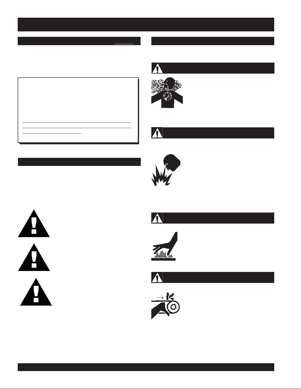
Lethal Exhaust Gases
Engine exhaust gases contain poisonous
carbon monoxide. This gas is colorless and
odorless, and can cause death if inhaled.
NEVER operate this equipment in a confined
area or enclosed structure that does not
provide ample free flow air.
Explosive Fuel
GASOLINE is extremely flammable, and its
vapors can cause an explosion if ignited. DO
NOT start the engine near spilled fuel or
combustible fluids. DO NOT fill the fuel tank
while the engine is running or hot. DO NOT
overfill tank, since spilled fuel could ignite if it
comes into contact with hot engine parts or
sparks from the ignition system. Store fuel in
approved containers, in well-ventilated areas
and away from sparks and flames. NEVER
use fuel as a cleaning agent.
DANGER: You WILL be KILLED or
SERIOUSLY injured if you do not follow
directions.
WARNING: You CAN be KILLED or
SERIOUSLY injured if you do not follow
directions.
CAUTION: You CAN be injured if you
do not follow directions.
Potential hazards associated with V304 vibration roller operation
will be referenced with Hazard Symbols which appear
throughout this manual, and will be referenced in conjunction
with Safety Message Alert Symbols.
Burn Hazards
Engine components can generate extreme heat.
To prevent burns, DO NOT touch these areas
while the engine is running or immediately after
operations. Never operate the engine with heat
shields or heat guards removed.
Rotating Parts
NEVER operate equipment with covers, or
guards removed. Keep fingers, hands, hair and
clothing away from all moving parts to prevent
injury.
PAGE 6 —V304 VIBRATORY ROLLER — OPERATION AND PARTS MANUAL — REV. #8 (11/13/09)
Page 7
V304 — SAFETY MESSAGE ALERT SYMBOLS
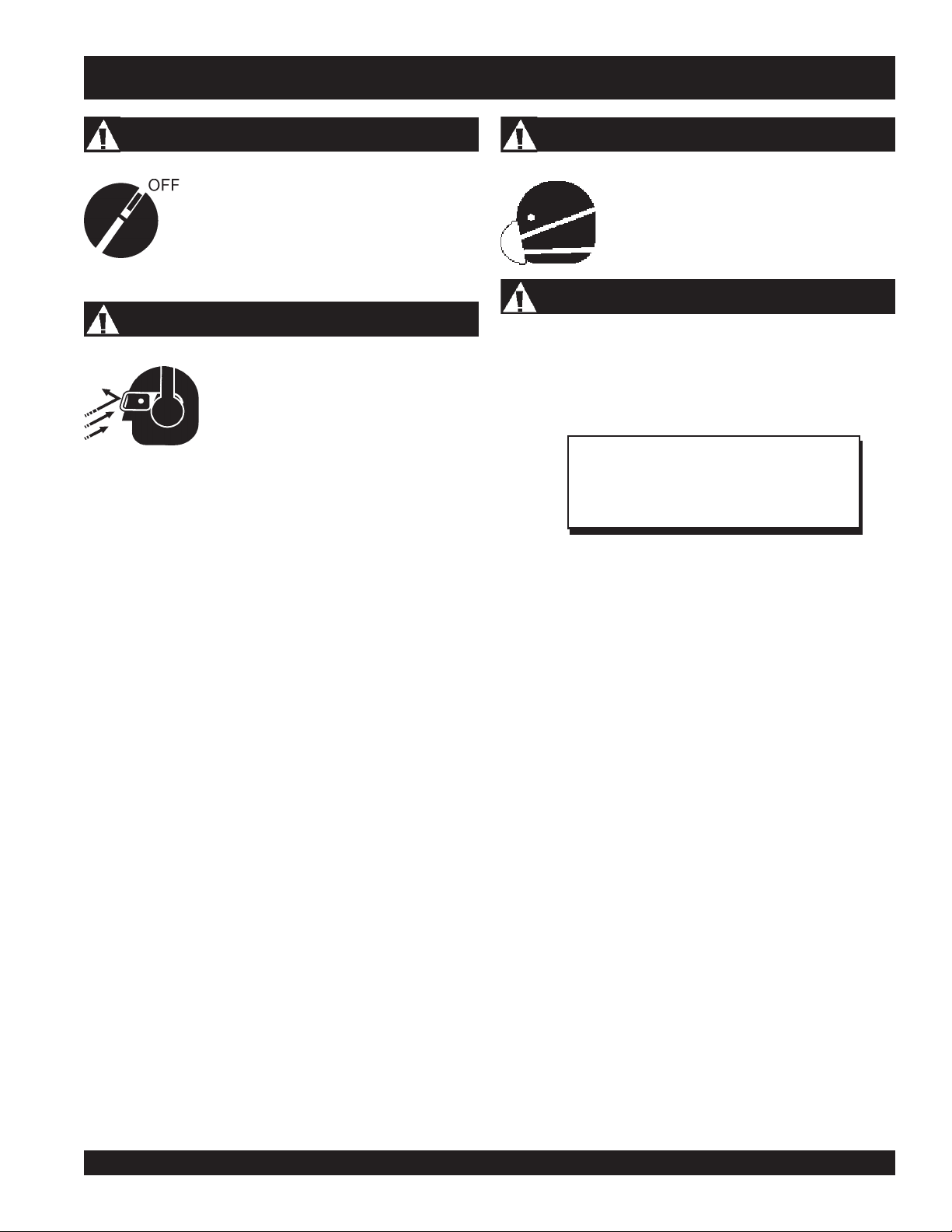
Accidental Starting
ALWAYS place the engine ON/OFF switch in
the OFF position, and remove the ignition key
when the machine is not in use.
Sight and Hearing hazard
ALWAYS wear approved eye and hearing
protection.
Respiratory Hazard
ALWAYS wear approved respiratory
protection.
Equipment Damage Messages
Other important messages are provided throughout this manual
to help prevent damage to your trash pump, other property, or
the surrounding environment.
NOTE
This compaction roller, other property, or the
surrounding environment could be damaged
if you do not follow instructions.
V304 VIBRATORY ROLLER — OPERATION AND PARTS MANUAL — REV. #8 (11/13/09) — PAGE 7
Page 8
RULES FOR SAFE OPERATION
■
CAUTION:
Failure to follow instructions in this manual may
lead to serious injury or even death! This
equipment is to be operated by trained and
qualified personnel only! This equipment is for
industrial use only.
The following safety guidelines should always be used when
operating the V304 Vibration Roller:
GENERAL SAFETY
■
DO NOT operate or service this equipment before
reading this entire manual.
■
This equipment should not be operated by
persons under 18 years of age.
■
NEVER operate this equipment without proper
protective clothing, shatterproof glasses, steeltoed boots and other protective devices required
by the job.
■
NEVER operate this equipment when not feeling
well due to fatigue, illness or taking medicine.
■
NEVER operate this equipment under the
influence or drugs or alcohol.
■
NEVER use accessories or attachments, which are not
recommended by Multiquip for this equipment. Damage to
the equipment and/or injury to user may result.
■
Manufacture does not assume responsibility for any accident
due to equipment modifications.
■
Whenever necessary, replace nameplate, operation and
safety decals when they become difficult read.
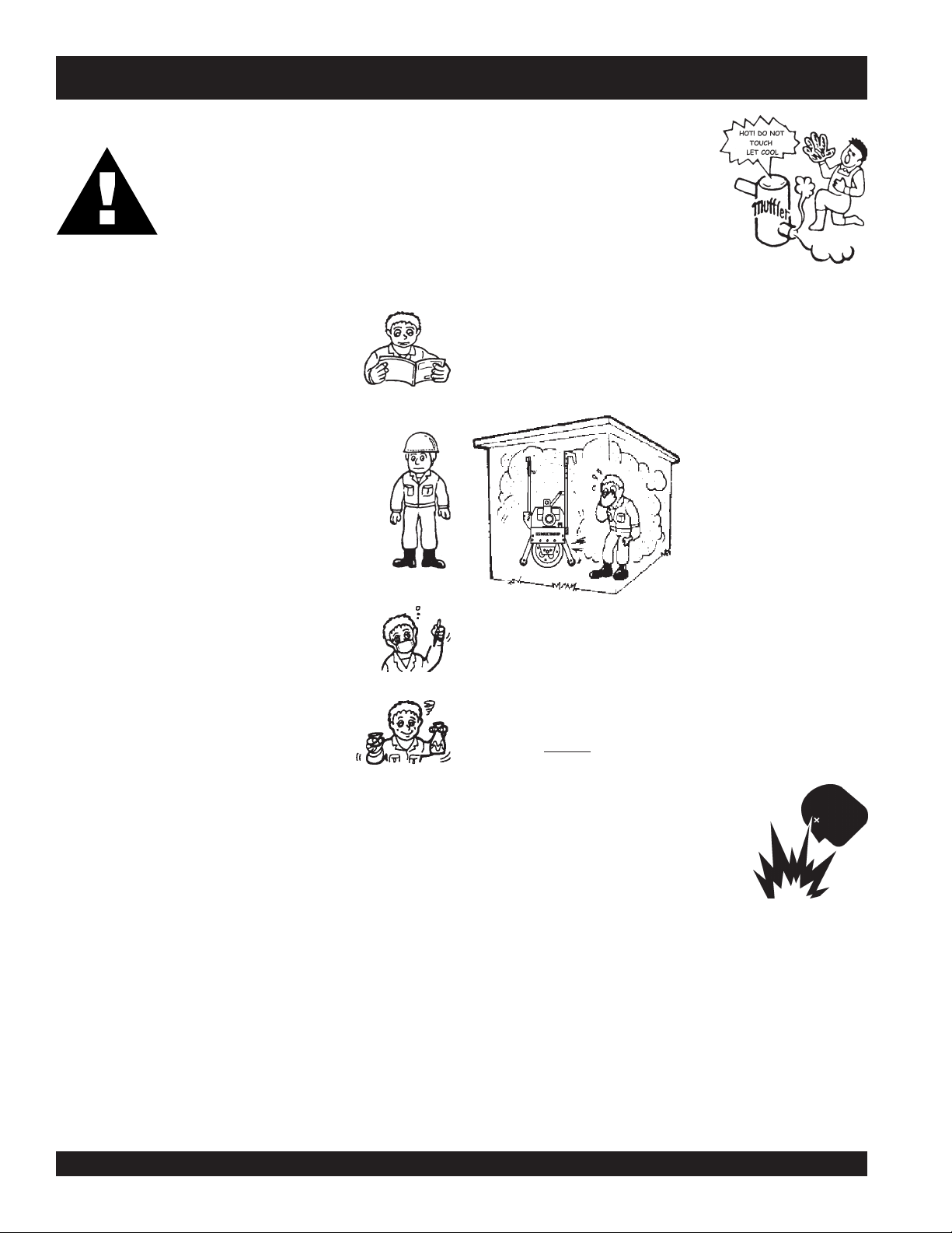
NEVER touch the hot exhaust manifold,
muffler or cylinder. Allow these parts to
cool before servicing engine or pump.
■
High Temperatures – Allow the engine to cool before adding
fuel or performing service and maintenance functions. Contact
hot
with
■
The engine of this roller requires an adequate free flow of
■
ALWAYS refuel in a well-ventilated area, away from sparks
and open flames.
■
ALWAYS use extreme caution when working with flammable
liquids. When refueling, stop the engine and allow it to cool.
DO NOT
could result from fuel vapors, or if fuel is spilled on a hot
engine.
■
NEVER operate the vibration roller in
an explosive atmosphere or near
combustible materials. An explosion or
fire could result causing severe
harm or even death.
■
Topping-off to filler port is dangerous, as it tends to spill fuel.
components can cause serious burns.
cooling air. Never operate
the roller in any enclosed
or narrow area where free
flow of the air is restricted. If
the air flow is restricted it
will cause serious damage
to the pump or engine and
may cause injury to people
and property. Remember
the roller's engine gives off
DEADLY gases.
smoke around or near the machine. Fire or explosion
bodily
■
ALWAYS check the machine for loosened threads or bolts
before starting.
PAGE 8 —V304 VIBRATORY ROLLER — OPERATION AND PARTS MANUAL — REV. #8 (11/13/09)
Page 9

■
NEVER Run engine without air cleaner. Severe engine
damage may occur.
■
ALWAYS read, understand, and follow procedures in
Operator’s Manual before attempting to operate equipment.
■
ALWAYS be sure the operator is familiar with proper safety
precautions and operations techniques before using pump.
■
ALWAYS store equipment properly when it is not being used.
Equipment should be stored in a clean, dry location out of the
reach of children.
■
DO NOT operate this roller with hydrostatic oil temperature
higher than 180 degrees Fahrenheit.
■
NEVER leave the roller unattended, turn off engine and place
lock handle in upright position.
■
CAUTION must always be observed while servicing this roller.
Rotating parts can cause injury if contacted.
■
DO NOT leave roller with engine running. Use chock blocks
if parking roller on a grade.
■
NEVER ride on a walk-behind roller in unshored trenches or
near steep, unsupported banks. The vibration caused by the
roller could cause a cave-in.
■
ALWAYS use extreme care when walking behind the roller,
avoid having your feet or clothing getting caught under the
dolly wheels or roller.
■
Whenever possible try and stand to one side of the roller
rather than directly behind it.
■
ALWAYS use extreme care when operating near obstructions,
on slippery surfaces, grades and side slopes.
■
ALWAYS wear slip resistant safety shoes or boots.
■
Unauthorized equipment modifications will void all
warranties.
■
Uneven grades can cause the handle to
unexpectedly, striking the operator by surprise.
■
When working on slopes, avoid
possible. Operate up and down travel only. Remember, the
danger of sliding on and/or tripping on steep slopes is always
present
■
NEVER ride on a walk-behind roller unless it is designed to
accommodate riders and an appropriate seat is provided.
■
Refer to the
questions or information.
Engine Owner's Manual
sidehill travel
raise
or
lower
whenever
for engine technical
■
■
■
Emergencies
■
Maintenance Safety
■
■
■
■
■
■
■
Lifting
■
■
RULES FOR SAFE OPERATION
High Temperatures – Always stop engine and allow the
engine to cool before adding fuel, oil or performing service
hot
and maintenance functions. Contact with
cause serious burns.
NEVER engage the "
parked on an incline.
NEVER disconnect any
These devices are intended for operator safety. Disconnection
of these devices can cause severe injury, bodily harm or even
death! Disconnection of any of these devices will void all
warranties.
ALWAYS know the location of the nearest
and
first aid kit
Also know the phone numbers of the nearest
doctor
invaluable in the case of an emergency.
ALWAYS check the roller's transport hooks. Make sure the
hooks are secure and tight before lifting the machine.
and
fire department
NEVER lubricate components or attempt service on a running
machine.
ALWAYS allow the machine a proper amount of time to cool
before servicing.
Keep the machinery in proper running condition.
Fix damage to the machine immediately and always replace
broken parts.
Dispose of hazardous waste properly. Examples of potentially
hazardous waste are used motor oil, fuel and fuel filters.
DO NOT use food or plastic containers to dispose of
hazardous waste.
DO NOT pour waste, oil or fuel directly onto the ground,
down a drain or into any water source.
The roller has an operating weight of approximately 1,045
lbs. (474 Kg). Use lifting equipment capable of lifting this
weight.
free wheel engagement leve
"emergency or safety devices"
. Know the location of the nearest telephone.
. This information will be
components can
r" when
.
fire extinguisher
ambulance
,
V304 VIBRATORY ROLLER — OPERATION AND PARTS MANUAL — REV. #8 (11/13/09) — PAGE 9
Page 10
OPERATION AND SAFETY DECALS
Machine Safety Decals
The V304 Compaction Roller is equipped with a number of safety decals. These decals are provided for operator safety and
maintenance information. The illustration below and on the next page shows these decals as they appear on the machine. Should
any of these decals become unreadable, replacements can be obtained from your dealer.
P/N 511782
ESSICK
A MULTIQUIPCOMPANY
1. Do not operate or service this machine before reading
the operating and maintenance manual.
2. Keep all inexperienced and/or unauthorized people away from
equipment at all times
3. Do not operate this equipment unless all guards and safety
devices are attached and in place.
4. Keep this equipment in safe operating at all times.
5. Caution must be exercised while servicing this equipment.
Rotating and moving parts can cause injury if contacted.
6. Stop engine and allow to cool before adding fuel or oil.
7. Stop engine when leaving equipment.
8. Block unit when parking on a slope.
9. Unauthorized equipment modifications will void all warranties.
ESSCICK CONSTRUCTION PRODUCTS AMULTIQUIP COMPANY CARSON, CALIFORNIA
OFF
V
I
B
R
A
T
I
O
N
ON
512071
HYDRAULIC OIL
SHELL TELLUS 32
CHECK LEVEL EVER 50 HOURS
SAFETY INSTRUCTIONS
F
O
R
W
A
R
D
511766
WATER TANK
R
E
V
E
R
S
E
948438
511767
511768
WARNING
To avoid injury,
you MUST read
and understand
operator’s manual
before using this
machine.
This machine to
be operated by
qualified
personnel only.
Ask for training
948501
as needed.
USE COCOA MAT ONLY
WHEN ROLLING ASPHALT
LIFT FROM ROLL
WHEN NOT REQUIRED
CAUTION
ATTACH SAFETY CHAIN
DURING TRANSPORT
PRE-WET MATS
BEFORE USING
948366
PUSH
TO STOP
9486330
P/N 35137
948044
511769
TURN ON
WATER TANK
NAMEPLATE
D
E
W
O
P
R
OUTLET VALVE
948484
CONTACT MULTIQUIP
SERVICE DEPT.
PAGE 10 —V304 VIBRATORY ROLLER — OPERATION AND PARTS MANUAL — REV. #8 (11/13/09)
C
O
D
E
A
T
P/N 13118
Page 11

V304 — SPECIFICATIONS
SNOITACIFICEPSENIGNE.1ELBAT
ledoMEAQ1K043XGadnoH0160SYO43HEniboR
epyT
XeroB
ekortS
tnemecalpsiD)cc733(.uc06.02)cc833(.uc36.02)
tuptuOxaM.M.P.R0063/.P.H11.M.P.R0063/.P.H11.M.P.R0063/.P.H01
knaTleuF
yticapaC
leuFenilosaGelibomotuAd
liOebuL
enignE
yticapaC
enignE
deepS
daoLlluF
enignE
deepS
eldIlluF
renaelCriAtnemelElauDtnemelElauDtnemelElauD
enignE
noitacirbuL
deepS
lortnoC
dohteM
gnitratS
dohteM
)HXWXL(noisnemiD
thgieWteNyrD
elooc-riA
i2.3
aG.S.U95.1.xorppA)sretil6(snollaG.S.U6.1.xorppA )sretil1.6(snollaG.S.U56.1.xorppA
edaelnUenilosaGelibomotuAdedaelnUleuFleseiD
ew-ylFlagufirtneCepyTthgiew-ylFlagufirtneCepyTthgiew-ylFlagufirtneC
daehrevo,ekorts4d
latnoziroh,rednilycelgnis,evlav
enigneenilosagtfahs
.ni05.2X.n
)mm46x88(
)sretil6(snoll
)tq61.1(sretil1.1)tq72.1(sretil2.1)tq47.1(sreti
001±mpr0562001±mpr0562001±mpr0562
001±mpr0541001±mpr0541001±mpr
)edarGliO(03-W01EAS
)ssalCecivreS(FSroGS
epyTthgi
tratScirtcelE/lioceRtra
mm4.71X7.71X0.51
)mm344X054X083(
1
tratScirtcelE).gK13(sbl4.86tratScirtcelE
lycelgnis,evlav
).gK33(sbl8.28
daehrevo,ekorts4delooc-riA
latnoziroh,redni
enigneenilosagtfahs
.ni04.2X.ni13.3
)mm16x48(
edarGliO(03-W01EAS
)
ssalCecivreS(FSroGS
tScirtcelE/lioceRtratScirtcelE/lioceR
mm90.01X19.71X38.5
)mm584X554X204(
tratSlioceR).gK03(sbl1.66
l56.1
0541
/EDEA001LramnaY
)devorppAAPE(3KMVEDEE001L
-riaelcyc-4lacitrev,rednilycelgniS
leseiddelooc
.ni67.2X.ni93.3
)mm07x68(
cc604(.uc87.42
)edarGliO(03-W01EAS
ssalCecivreS(FSroGS
mm54.91X05.81X24.61
)mm494X074X714(
tratScirtcelE).gK35(sbl711
tratSlioceR).gK84(sbl601
SNOITACIFICEPSRELLOR.2ELBAT
ecroFtcapmI)gk296,1(.sbl037,3
ycneuqerFmpv004,4
ytilibaedarGtnecreP12
htdiWmurD)2
.67(.ni03
htdiWllarevO)1.09(.ni5.53
metsySevirDcitatsordyH
deepSlevarT)hpk4-0(hpm5.2-0
yticapaCknaTretaW)sret
il4.13(.lag3.8
triDfohtpeDnoitcapmoC)mc9.42(ni01
tlahpsAfohtpeDnoitcapmoC)mc9.9(0.4
edutilpmAnoitarbiV.ni91
0.
)ytpmE(thgieWgnitarepOniboR/adnoH).gk474(.sbl540,1
)ytpmE(thgieWgnitarepOramnaY).gk384(.sbl560,1
V304 VIBRATORY ROLLER — OPERATION AND PARTS MANUAL — REV. #8 (11/13/09) — PAGE 11
Page 12
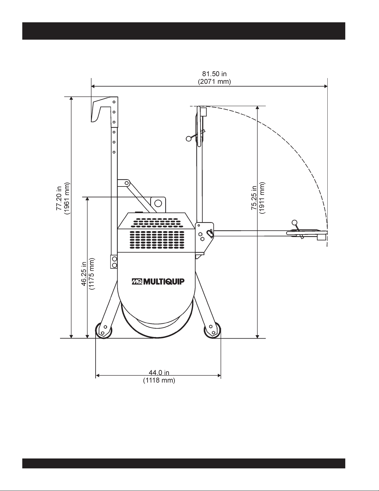
V304 — DIMENSIONS
Figure 1. V-30-4 Roller Dimensions Side View)
PAGE 12 —V304 VIBRATORY ROLLER — OPERATION AND PARTS MANUAL — REV. #8 (11/13/09)
Page 13
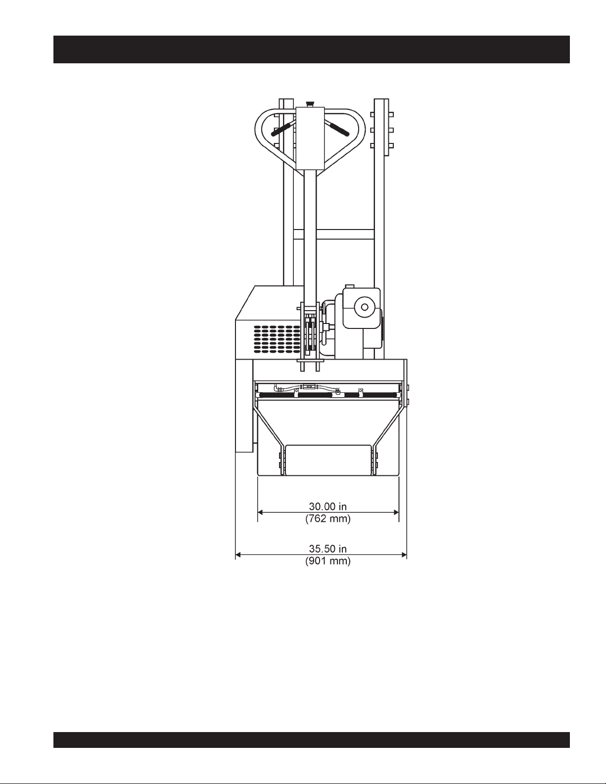
V304 — DIMENSIONS
Figure 2. V304 Roller Dimensions (Front View)
V304 VIBRATORY ROLLER — OPERATION AND PARTS MANUAL — REV. #8 (11/13/09) — PAGE 13
Page 14
V304 — ROLLER COMPONENTS
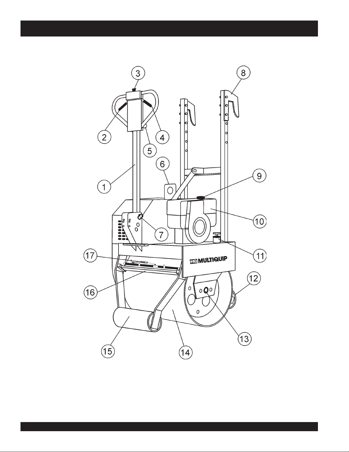
Figure 3. Roller Components 1
PAGE 14 —V304 VIBRATORY ROLLER — OPERATION AND PARTS MANUAL — REV. #8 (11/13/09)
Page 15
V304 — ROLLER COMPONENTS
Figure 3 shows the location of the components and basic
components for the V304 compaction roller. The function of each
component or control is described below:
1. Multi-Position Handle Bar – This bar can be set to
four different positions, park, high, middle and low. When
transporting the roller,
the upright (stow) position.
2. Forward Travel Lever – This is a variable speed control
lever. Squeeze this lever to make the roller travel in a
forward direction.
3. Emergency Stop Button – Press this button to stop
the roller in the event of an
this button as a means of stopping the roller under
normal conditions. When starting the engine make sure
that this push-button switch is in the up position.
4. Reverse Travel Lever – This is a variable speed control
lever. Squeeze this lever to make the roller travel in a
reverse direction.
5. Vibration Control Lever – Move this lever to the ON
position an the eccentric will produce a vibration
frequency of 4,400 vpm (vibrations per minute). Move
the lever to the OFF position to stop the vibrations.
6. Lifting Hook Eye – Attach a crane or lifting device to
this lifting hook eye. The lifting device should have a
lifting capacity of 1,000 lbs. (450 kg.)
7. Handle Bar Release Pin – Remove this pin to position
the handle bar to the desired position. Make sure to
reinsert release pin and cotter pin after each new
position.
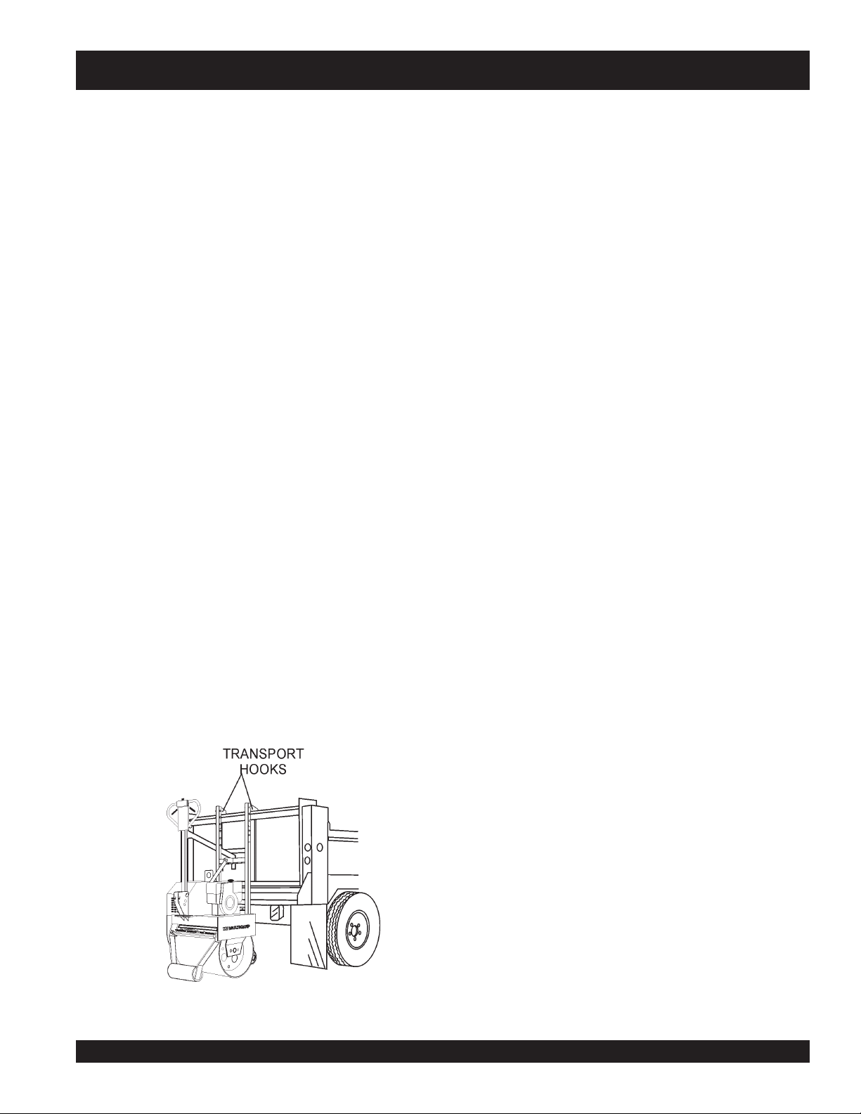
8. Transport Hooks – These hooks are used in the
transportation of the roller (Figure 4). The hooks allow
the roller to hang over the tailgate of a dump truck.
always
have the handle bar in
emergency
. DO NOT use
9. Fuel filler Port – Remove this cap to determine the
amount of fuel in the fuel tank. If low, add fuel through
this port.
10. Engine – This roller uses three different types of
engines, Honda GX-340, Robin EH-34 and Yanmar L100
(Diesel). For additional engine information read the
engine Owner's Manual supplied with the roller.
11. Water Tank Filler Port – Remove this cap to determine
the amount of water in the water tank. If low, add
water through this port. This water tank holds 8.3 gallons
(31.4 liters) of water.
12. Rear Stabilizer Roller – This roller aids the roller in
maintaining stability (prevents tipping) and simplifies
handling when maneuvering the roller.
13. Zerk Fittings – Lube and grease these fittings as
recommended in the maintenance section of this
manual.
14. Main Vibratory Roller – This roller is 30 inches wide
steel drum
prevent asphalt marring.
15. Front Stabilizer Roller – This roller aids the roller in
maintaining stability (prevents tipping) and simplifies
handing when maneuvering the roller.
16. Coco Mat/Scrapper Blade – This mat and blade helps
prevent the buildup of material between the drum and
frame. When using the roller for earth compaction DO
NOT let the mat come in contact with the roller drum. A
hook type latch is provide to keep the mat away from the
drum.
17. Sprinkler System/Water Shut-off Valve – A gravity
feed spray bar is provided for the wetting the roll for
asphalt pavement. Turn the water valve to the
position to let water flow, return this valve to the closed
position when water is not required. In addition a water
filter has been provided to prevent foreign matter from
clogging the spray bar holes. Clean this filter as
referenced in the maintenance section of this manual.
clean
with beveled edges. The beveled help
open
Figure 4. Transport Hooks
V304 VIBRATORY ROLLER — OPERATION AND PARTS MANUAL — REV. #8 (11/13/09) — PAGE 15
Page 16
V304 — ROLLER COMPONENTS
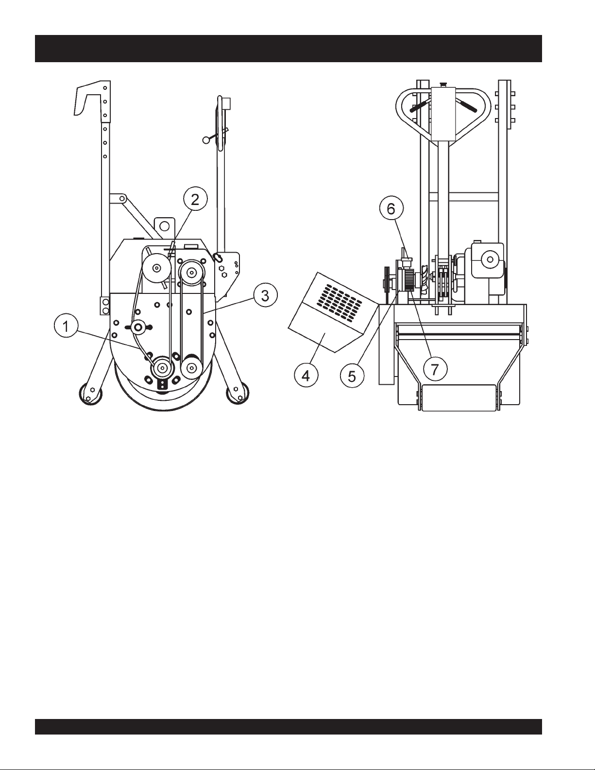
Figure 5. Roller Components 2
Figure 5 shows the location of additional components for the
V304 compaction roller. The function of each component or
control is described below:
1. Vibration Drive V-Belt – This belt is require to make
the roller vibrate. Check this V-belt as outlined in the
maintenance section of this manual.
2. Free Wheel Engagement Lever – Under normal
conditions this lever should be place in the
position (engaged). In the event the roller becomes
disable and must be moved (will not start), place the
lever in the side position (disengaged).
This will allow the roller drum to rotate (free wheel).
IMPORTANT!, this lever is only to be used in cases
where the roller has be disabled. In normal operating
conditions this lever should be left in the engaged
position (forward)
PAGE 16 —V304 VIBRATORY ROLLER — OPERATION AND PARTS MANUAL — REV. #8 (11/13/09)
forward
3. Travel Drive V-Belt – This belt is require to make the
roller travel in a forward or reverse direction. Check this
V-belt as outlined in the maintenance section of this
manual.
4. Compartment Hood – Remove this hood to gain
access to the V-belts, hydrostatic pump, coupling
components, free wheel engagement lever etc.
5. Hydrostatic Pump – Provides hydraulic pressure to
the drive system.
6. Hydrostatic Fluid Reservoir – Fill this reservoir with
hydrostatic transmission fluid. Fill with Mobil 300, GM
Dextron B or Ford MCZ-41A type transmission fluid.
7. Cogged- Drive Belt – This belt is used with the
hydraulic pump. Check this cogged drive belt as outlined
in the maintenance section of this manual.
Page 17
V304 — ENGINE COMPONENTS
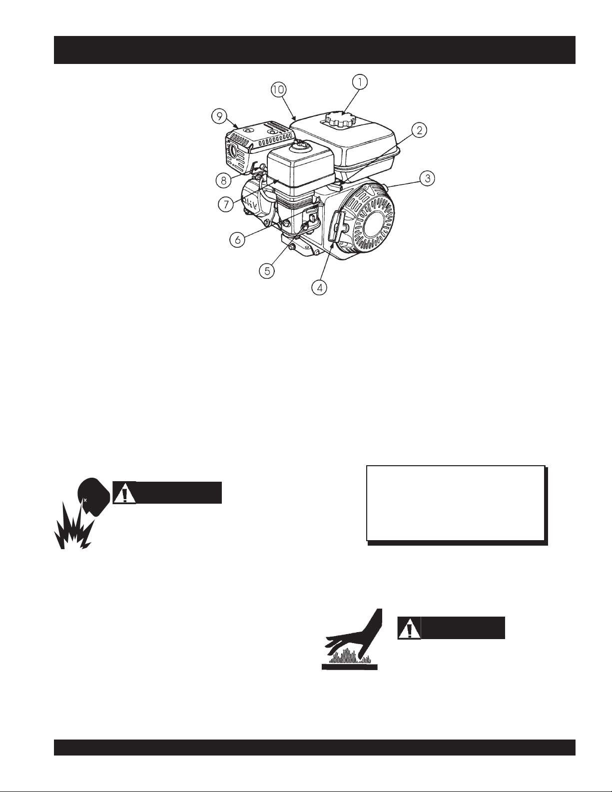
Figure 6. Engine Controls and Components (HONDA)
INITIAL SERVICING
The engine (Figure 6) must be checked for proper lubrication and
filled with fuel prior to operation. Refer to the manufacturers Engine
manual for instructions & details of operation and servicing.
1. Fuel Filler Cap – Remove this cap to add unleaded
gasoline to the fuel tank. Make sure cap is tightened
securely. DO NOT over fill.
5. Fuel Valve Lever – OPEN to let fuel flow, CLOSE to stop
the flow of fuel.
6. Choke Lever – Used in the starting of a cold engine, or in
cold weather conditions. The choke enriches the fuel
mixture.
7. Air Cleaner – Prevents dirt and other debris from entering
the fuel system. Remove wing-nut on top of air filter
cannister to gain access to filter element.
WARNING
WARNING
Adding fuel to the tank should be accomplished only
when the engine is stopped and has had an
opportunity to cool down. In the event of a fuel spill,
DO NOT attempt to start the engine until the fuel residue has been
completely wiped up, and the area surrounding the engine is dry.
2. Throttle Lever – Used to adjust engine RPM speed (lever
SLOW
advanced forward
FAST
).
3. Engine ON/OFF Switch – ON position permits engine
starting, OFF position stops engine operations.
4. Recoil Starter (pull rope) – Manual-starting method. Pull
the starter grip until resistance is felt, then pull briskly and
smoothly.
, lever back toward operator
8. Spark Plug – Provides spark to the ignition system. Set
spark plug gap to 0.6 - 0.7 mm (0.028 - 0.031 inch) Clean
spark plug once a week.
9. Muffler – Used to reduce noise and emissions.
while the engine is running or immediately after operating. NEVER
operate the engine with the muffler removed.
10. Fuel Tank – Holds unleaded gasoline. For additional
information refer to engine owner's manual.
NOTE
Operating the engine without an air filter,
with a damaged air filter, or a filter in need of
replacement will allow dirt to enter the
engine, causing rapid engine wear.
WARNING
Engine components can generate extreme heat.
To prevent burns, DO NOT touch these areas
V304 VIBRATORY ROLLER — OPERATION AND PARTS MANUAL — REV. #8 (11/13/09) — PAGE 17
Page 18
V304 — GENERAL INFORMATION
The V304 Vibratory Roller is a walk-behind vibratory roller
specifically designed for the compaction and patching of asphalt
type surfaces.
The compaction force is delivered by a 30-inch wide steel drum
with beveled edges to help prevent asphalt
enclosed hydrostatic drive system offers a variable speed control
as well as smooth acceleration and braking
HYDROSTATIC DRIVE SYSTEM
This hydrostatic design offers a smooth performance, because
of a fully integrated hydrostatically actuated drive system, which
provides a variable speed control under varying load conditions.
Power from the hydraulic drive system is transferred via a drive
belt to a gear reducer.
CONTROLS
The forward-reverse control lever (located on the handle)
operates the hydrostatic pump which governs the roller speed
and direction of travel. The neutral position of this lever will cause
the roller to stop. The vibration control when actuated will apply
a force of 4,400 vpm (vibrations per minute). This vibratory feature
is controlled by an eccentric shaft via an operator controlled
mechanical clutch.
marring
. A fully
SPRINKLER SYSTEM
A 8.3 gallon (31.4 liters) water tank with a gravity feed spray bar
is provided for wetting the roll for asphaltic pavement rolling.
Before starting an asphalt rolling job, be sure all spray bar holes
are clear of dirt or foreign matter and are working. A coco mat is
provided to insure an even distribution of water.
DO NOT leave the coco mat in contact with the roll (drum) when
the roller is used for earth compaction. A hook is provided to hold
the mat away from the roll. The coco mats are intended to prevent
the build-up of material between the drum and the frame.
Always use clean fresh water in the water tank. To prevent rust
and foreign debris from clogging the spray bar holes, drain and
flush water tank and spray bars every 30 days.
TRANSPORTATION
To help transport the roller from job site to job site, adjustable
transport hooks have been provided. These transport hooks allow
an operator to place the roller on the tailgate of a dump truck
without any assistance. The control handle of the V304 roller
can be folded vertically for ease of transport and storage.
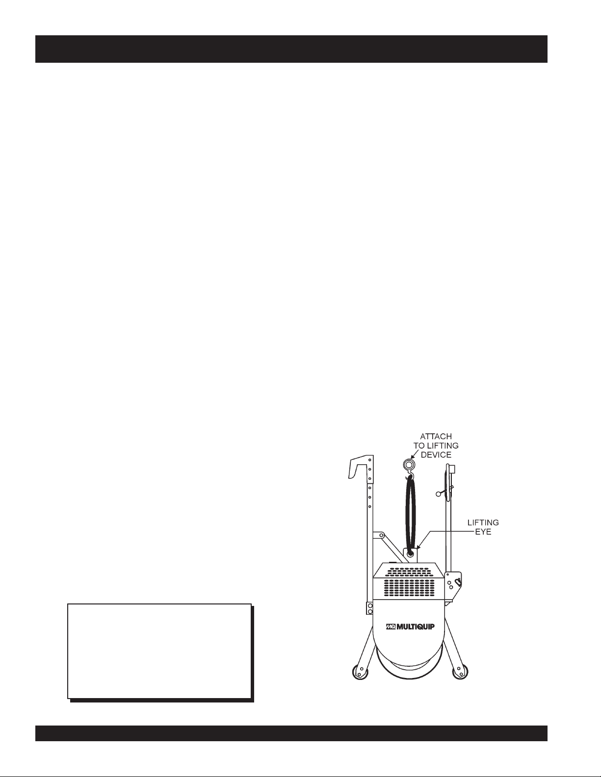
LIFTING THE ROLLER
When lifting of the roller is required (Figure 7), attach a suitable
hook or shackle to the
lifting device is capable of lifting 1,045 lbs (450 kg).
lifting eye
of the roller. Make sure the
FREE WHEEL ENGAGEMENT LEVER
The hydrostatic transmission is equipped with a free wheel
engagement lever, which, when actuated, allows the oil to circulate
freely within the roller, thereby permitting the roller to be moved
without the engine running. This lever is only to be used in the
event the roller is disabled.
This lever is located on the that side of the transmission which
faces the front of the roller. It is actuated by placing the handle
into the side-lock position. To gain access to this lever raise the
roller's hood. DO NOT raise hood while engine is running, STOP
engine.
NOTE
.
In normal operating conditions the roller
will not move in a forward or reverse
direction unless the free wheel
engagement lever is in the engage position
(forward).
Figure 7. Lifting The Roller
PAGE 18 —V304 VIBRATORY ROLLER — OPERATION AND PARTS MANUAL — REV. #8 (11/13/09)
Page 19
V304 — GENERAL INFORMATION
CAUTION :
while it is being lifted or moved.
CAUTION :
ONLY! use steel ropes or chains that are
capable of lifting at least 1,045 lbs (450 kg).
CAUTION :
NEVER! use any other part of the roller for
lifting purposes. Use the lifting eye. Using other
parts of the roller for lifting will cause severe
damage to the roller,
NEVER! stand under, or get onto the roller
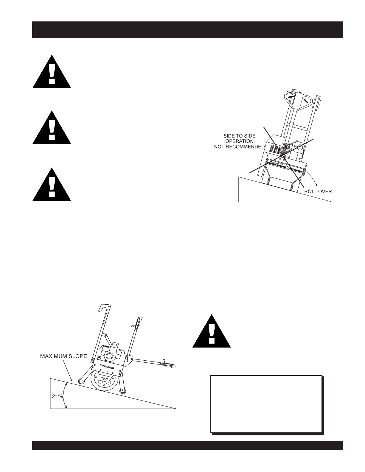
Tipping (Rollovers)
NEVER! operate the roller on side slopes (Figure 9). The
possibility exist that the roller could tip over (roll over), thus
causing bodily harm even death and serious damage to the
equipment.
Figure 9. Tipping (Rollover)
In the event the roller does tip over, extreme care must be taken
OPERATING ON SLOPES
Special care must be taken when operating the roller on hills or
slopes. There exist the possibility of serious injury to the operator
and severe damage to the roller in the event of a roll over.
ALWAYS operate the roller up and down hills rater than from
side to side. For safe operation hillside slopes should not exceed
12 degree (21 % grade). See Figure 8 below.
to prevent damage to the engine. When the roller has been
tipped over, oil from the engine crankcase can flow into the
combustion chamber, which can severely damage the engine
the next time it is started.
IMMEDIATELY after a unit has tipped over upright the unit as
soon as possible to prevent oil from leaking into the combustion
chamber.
CAUTION :
Figure 8. Recommend Slope
To prevent damage to the engine after a
rollover, the unit must NOT be started. NEVER
start a unit after a rollover. CONTACT your
nearest authorized multiquip dealer for
instructions or servicing.
NOTE
NEVER! operate the roller on
The roller may tip over causing injury to
personnel and severe damage to the
equipment
side slopes
.
V304 VIBRATORY ROLLER — OPERATION AND PARTS MANUAL — REV. #8 (11/13/09) — PAGE 19
Page 20
Before Starting
1. Read safety instructions at the beginning of manual.
2. Clean the ROLLER, removing dirt and dust, particularly the
engine cooling air inlet, carburetor and air cleaner.
3. Check the air filter for dirt and dust. If air filter is dirty, replace
air filter with a new one as required.
4. Check carburetor for external dirt and dust. Clean with dry
compressed air.
V304 — INSPECTION
Figure 11. Engine Oil Dipstick (Oil Level)
5. Check fastening nuts and bolts for tightness.
Engine Oil Check
1. To check the engine oil level, place the saw on secure level
ground with the engine stopped, and the diamond blade
removed.
2. Remove the filler cap/dipstick from the engine oil filler hole
(Figure 10) and wipe it clean.
Figure 10. Engine Oil Dipstick (Removal)
NOTE
Some engines used with the V304 Roller
have an oil Alert System. This system will
automatically stop the in the event of low
oil level. ALWAYS be sure to check the
engine oil level prior to starting the engine.
epyTliO.3elbaT
nosaeS erutarepmeT epyTliO
remmuS rehgiHroC°52 03-W01EAS
llaF/gnirpS C°01~C°52 02/03-W01EAS
retniW rewoLroC°0 01-W01EAS
Fuel
3. Insert and remove the dipstick without screwing it into the filler
neck. Check the oil level shown on the dipstick.
4. If the oil level is low (Figure 11), fill to the edge of the oil filler
hole with the recommended oil type (Table 3). Maximum oil
capacity is 400 cc.
NOTE
CAUTION :
Reference manufacturer engine manual for
specific servicing instructions.
PAGE 20 —V304 VIBRATORY ROLLER — OPERATION AND PARTS MANUAL — REV. #8 (11/13/09)
NEVER fill the fuel tank (Figure 12) while
the engine is running or in the dark. Fuel
spillage on a hot engine can cause a fire
or explosion. If fuel spillage occurs, wipe
up the spilled fuel completely to prevent
fire hazards.
DO NOT smoke while refueling, motor
fuels are highly flammable and can be
dangerous if mishandled.
Page 21

V304 — INSPECTION
Explosive Fuel
Gasoline Check
1. Remove the gasoline cap located on top of fuel tank.
2. Handle Fuel in a safety container. If the container does not
have a spout use a funnel.
3. Visually inspect to see if fuel level is low. If fuel is low,
replenish with unleaded fuel. When refueling, be sure to use
a strainer for filtration. DO NOT top-off fuel. Wipe up any
spilled fuel.
Water Tank
1. Fill the water tank (Figure 13) with clean water, and verify
that valve for the water tank is
4. Pay attention to the fuel tank capacity when replenishing
fuel. Refer to the fuel tank capacity listed on page 11,
Engine Specification Table 1.
closed
.
Figure 12. Fuel Tank Filler Port
Figure 13. Water Tank Filler Port
Hydraulic Pump Fluid
1. Visually inspect the hydraulic fluid in the hydraulic reservoir
(Figure 14). If the hydraulic fluid is low, fill the reservoir with
Mobil 300, GM Dextron B or Ford MZC-41A type hydraulic
transmission fluid to the correct level. The correct hydraulic
fluid level will be indicated on the reservoir.
Figure 14. Hydraulic Reservoir Filler Port
V304 VIBRATORY ROLLER — OPERATION AND PARTS MANUAL — REV. #8 (11/13/09) — PAGE 21
Page 22

V304 — INSPECTION
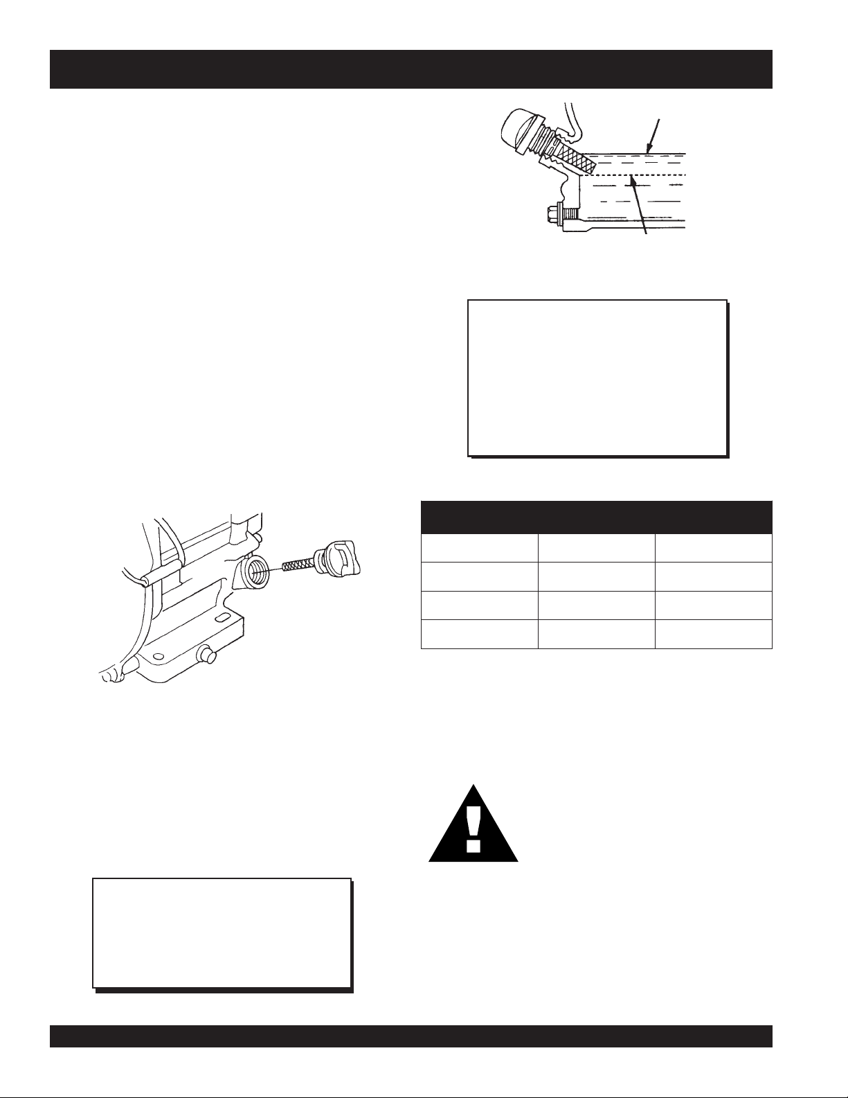
Gearbox Lubrication
1. Remove the oil fill drain plug on the gearbox (Figure 15). If
the oil level is
drain plug.
2. If the level of the oil in the gearbox is
when the drain plug is removed. Add gearbox oil, type SAE
90 through this drain opening. Fill until oil begins to leak out
from the drain opening cavity. If gearbox oil is
leak out when drain plug is removed. Retighten drain plug.
correct
oil will begin to leak out. Retighten
low
, no oil will leak out
low
no oil will
Vibratory and Travel V-Belt Tension
Check the tension of the vibratory and travel V-belts
(Figure 16). This tension can be checked by the amount
of deflection when the belt is pressed midway between
the two pulleys. The deflection of the travel belt should
be approximately 3/4 of an inch (2 cm.), the vibratory Vbelt should have a deflection of approximately 2 to 2-1/2
inches (5 to 6 cm.)
Clogged Drive Belt Tension
Check the tension of the clogged V-belt (hydrostatic pump). This
tension can be checked by the amount of deflection when
the belt is pressed midway between the two pulleys. The
deflection of the travel belt should be approximately 1/2
of an inch (1.27 cm.).
Figure 16. Vibratory, Travel and Pump Belts
Figure 15. Gearbox Fill and Drain Plug
PAGE 22 —V304 VIBRATORY ROLLER — OPERATION AND PARTS MANUAL — REV. #8 (11/13/09)
Page 23

Initial Start-up Instructions
Handle Bar Adjustment
Adjustment of the handle bar is made by removing the
handle bar
released pin has been removed, position handle bar to
desired height (Figures 17 and 18), then insert release
pin and lock with cotter pin.
hitch pin
, then pulling the release pin. Once
Starting
CAUTION:
V304 — INITIAL START-UP
Figure 18. Handle Positions 2
DO NOT attempt to operate the roller until the
Safety, General Information and Inspection
sections have been read and understood.
Depending on the type of engine installed on
roller, operating steps may vary somewhat. See
engine manufactures operating manual. The
following start-up procedure makes reference
to a HONDA engine.
Figure 17. Handle Positions 1
1. ALWAYS make sure that the emer-
gency stop button (Figure 19) is
pulled all the way out (disengage).
Figure 19. Emergency Stop Button
2. Place the engine
position.
fuel valve lever
(Figure 20) to the "ON"
Figure 20. Engine Fuel Valve Lever
V304 VIBRATORY ROLLER — OPERATION AND PARTS MANUAL — REV. #8 (11/13/09) — PAGE 23
Page 24

V304 — INITIAL START-UP
3. Place the
position.
Figure 21. Engine Ignition Switch (0n Position)
Engine ON/OFF switch
NOTE
(Figure 21) in the "ON"
The CLOSED position of the choke lever enriches
the fuel mixture for starting a COLD engine. The
OPEN position provides the correct fuel mixture
for normal operation after starting, and for
restarting a warm engine.
Figure 23. Throttle Lever
6. Place the
"START" position. Hold until engine starts.
Engine ON/OFF switch
(Figure 24) to the
4. Place the
5. Place the
and
engine governor speed is factory set to ensure optimum
blade operating speeds.
Choke Lever
Figure 22. Choke Lever
throttle lever
slow
for starting. All sawing is done at full throttle. The
(Figure 22) in the "OPEN" position
(Figure 23) halfway between
fast
Figure 24. Engine Ignition Switch (Start Position)
NOTE
DO NOT keep the ignition switch in the
START
position for more than 5 seconds.
7. If the engine has started allow switch to return to ON
position, then slowly return the choke lever (Figure 22)
CLOSED
to the
repeat steps 1 through 5.
Before the roller is placed into operation, run the engine
8.
for several minutes. Check for fuel leaks, and noises that
would associate with a loose guard and/or covers.
9. All rolling is done at full throttle. Your engine governor has
been set at the factory to ensure an optimum speed
setting.
position. If the engine has not started
PAGE 24 —V304 VIBRATORY ROLLER — OPERATION AND PARTS MANUAL — REV. #8 (11/13/09)
Page 25

Operation
CAUTION :
NEVER perform service or maintenance
on the roller when the engine is running.
The engines used with this roller DO NOT
require a pre-mix of oil and gasoline.
Free Wheel Engagement Lever
Before the roller can be put into operation, check and make sure
that the free
engagement position (forward). Lift the compartment hood to
gain access to this lever.
wheel engagement lever
(Figure 25) is in the
Figure 27. Forward and Reverse Control Levers
1. Squeezing the left control lever (Figure 28) will cause the
roller to move in a
all the way towards the operator will achieve maximum
speed. Use a smooth squeezing action on the drive control
lever to prevent abrupt takeoffs.
V304 — OPERATION
Neutral Position
forward direction
. Squeezing the lever
Figure 25. Free Wheel Engagement Lever
Water Shut-off Valve
If the water sprinkler is going to be used for a roll of asphalt
paving, fill the water tank with clean water and turn the water
OPEN
valve to the
Directional Speed Control Levers
1. With the engine running, both directional and speed control
levers (Figure 27) should be in their neutral positions.
V304 VIBRATORY ROLLER — OPERATION AND PARTS MANUAL — REV. #8 (11/13/09) — PAGE 25
position (Figure 26).
Figure 26. Water Shut-Off Valve
2. Squeezing the
roller to move in a
ing action on the drive control lever to prevent abrupt take-offs.
Figure 28. Forward Control Lever
right
control lever (Figure 29) will cause the
reverse direction
Figure 29. Reverse Control Lever
. Use a smooth squeez-
Page 26

V304 — OPERATION
Vibratory Control
1. For vibratory action, with the engine running (full speed)
place the vibratory control lever ( Figure 30) to the ON
position. The roller will now produce a vibratory frequency of
4,400 vps.
2. Place the water valve in the CLOSED position (if used).
3. Place the
position, and let the engine idle for 3-5 minutes.
4. Place the
position and remove the key. Place the key in a save place.
CAUTION :
NEVER! engage vibrator on
asphalt
Figure 30. Vibratory Control Lever (ON)
type surfaces.
concrete
or
Figure 32. Engine Ignition Switch (OFF Position)
engine throttle lever
Engine ON/OFF switch
(Figure 23) in the
(Figure 32) in the "OFF"
slow
Shut-Down
1. Place the vibration control lever (Figure 31) on the roller to
the OFF position (vibration stops).
Figure 31. Vibratory Control Lever (OFF)
4. Place the engine
position.
5. Clean the entire roller with warm water and mild soap. Pay
close attention to the scrapper bar and spray bar holes,
making sure that no dirt or debris is present. Dirt and debris
can cause the sprinkler system to get clogged.
fuel valve lever
(Figure 20) in the OFF
PAGE 26 —V304 VIBRATORY ROLLER — OPERATION AND PARTS MANUAL — REV. #8 (11/13/09)
Page 27

V304 — MAINTENANCE
Maintenance
Vibrating Shaft Bearings (50 hrs)
The double row of self-aligning ball bearings on the vibrator
shaft are special bearings that are not available at the local
bearing supply houses. Lubrication of these bearings is very
important and should be lubricated after each 50 hours of
operation. Rotate roller drum so that grease fittings are towards
the lower front.
If it becomes necessary to tear down and reassemble the roller,
remove wash out and repack bearing housing with specified
grease. After cleaning and checking bearings, they should be
lightly packed with the specified grease.
It is essential that no end thrust be applied to these bearings. On
reassembly there should be approximately .060" (min) to .120"
(max) end float on the vibrator shaft, which may reduce when the
shaft reaches working temperature. The bearings must be a light
slip fit on the shaft to insure axial freedom.
Hydrostatic Transmission Fluid (50 hrs)
Inspect the fluid level in the hydraulic fluid reservoir every 50
hours of operation, if low, fill with Mobil 300, GM Dextron B or
Ford MZC-41A type hydraulic transmission fluid. Change
hydraulic transmission fluid on a yearly basis.
Scrapper Blades (Daily)
The scrappers blades should be cleaned daily after each use to
prevent the build-up of dirt, mud, tar and any other foreign matter
associated with pavement rolling. Use a high pressure water jet
(500-1000 psi) and a strong brush to clean the scrapper blades.
V-30-4 Roller (Daily)
Clean the roller daily after each use. If using a pressurized hose
keep the pressure between 500 and 1000 psi. Avoid using harsh
chemicals, mild detergent soap will do. Avoid direct high water
pressure to the engine, hoses and decals.
Water Tank (30 Days)
Drain and flush the water tank and spray bars every 30 days.
When refilling the water tank, use only clean water.
Adjusting or Changing Travel V-Belt
1. Un-lock the hood retaining latch and lift the hood to gain
access to the V-belts. To adjust the
four mounting screws on the reduction gearbox (Figure 33)
travel
V-belt, loosen the
Vibrator Clutch Assembly (100 hrs)
The clutch must be greased every 100 hours of operation. Stop
the engine with clutch engaged to check V-belt tension. See
"ensioning g the V-belts"
Engine and Vibratory Shaft Speed Check (100 hrs)
To check the engine and vibratory shaft speed the use of an
"Vibra-Tak" tool will be required.
To check engine speed, place the bottom of the Vibra-Tak tool
(knurled cap) on the engine shroud. Move sliding sleeve to a
position where the maximum throw of wire reed is obtained.
Take a reading from edge of sleeve and multiply reading by
1000. The result is the RPM's the engine is running at.
If the engine RPM speed is too fast or slow, consult the engine
owner's manual on how to adjust the engine speed.
To check the vibrations per minute (vpm) of the roller shaft, place
the bottom of the Vibra-Tak tool (knurled cap) on the roller drum
while the vibrating clutch is engaged. Adjust and read tool as
mentioned above. The
vpm.
vibratory shaft speed
should be 4400
2. Use the prypoint (Figure 33) to achieve correct amount of V-
belt tension. Tighten gearbox screws, and check belt tension
by verifying the amount of deflection when the belt is pressed
midway between the two pulleys. This deflection should be
approximately 3/4 of an inch (2 cm.)
Figure 33. Travel and Vibratory V-Belts
V304 VIBRATORY ROLLER — OPERATION AND PARTS MANUAL — REV. #8 (11/13/09) — PAGE 27
Page 28

V304 — MAINTENANCE
Adjusting or Changing Vibratory V-Belt
1. To adjust the vibratory V-belt, loosen the pulley tensioner
nut (Figure 33) and adjust the V-belt for approximately 2
to 2-1/2 inches (5 to 6 cm.) of deflection. Check V-belt
deflection when V-belt is pressed midway between the
two pulleys. When the correct amount V-belt deflection
has been achieved, retighten pulley tensioner nut.
2. IMPORTANT! always adjust the vibratory V-belt to the rec-
ommended belt tension. A tight V-belt will cause the roller to
vibrate even it the vibration control lever is in the OFF
position. Remember a loose V-belt will decrease the vibratory action or there may not be any vibratory action at all.
Adjusting or Changing Hydrostatic Pump Drive Belt
1. To change or adjust the clogged drive belt (Figure 34) for
the hydrostatic pump, loosen the four mounting bolts on the
hydrostatic pump. Move the pump unit towards the rear of the
roller and adjust the clogged belt for approximately 1/2 inch
(1.27 cm) deflection when the belt is pressed midway
between the two pulleys. When the correct amount of belt
deflection has been achieved, retighten hydrostatic pump
mounting screws.
Adjusting Control Rods
Travel Control Rod
1. To adjust the travel control rod (controls forward, reverse
2. On the travel control rod, loosen the counter nut on the
and neutral) it will be necessary to start the engine and run
low
it a
rod end
35, then rotate the rod end to acquire desired length.
Adjust travel rod so that its static position (no force applied
on drive control) falls into the neutral position. The roller
should not move once adjustment is complete. Retighten
all hardware.
speed.
. Remove retaining screw as shown in Figure
Figure 35. Travel and Vibratory V-Belts
Vibratory Control Rod
1. To adjust the vibratory control rod (controls vibration),
loosen the counter nut (Figure 3) on the rod end of the
Figure 34. Hydrostatic Pump Drive Belt
NOTE
Use
caution
when adjusting control rods, since
engine is running.
PAGE 28 —V304 VIBRATORY ROLLER — OPERATION AND PARTS MANUAL — REV. #8 (11/13/09)
vibratory control rod. Remove the retaining screw on
the rod end and rotate the rod to achieve the desired
rod length.
2. Continue adjusting, until clutch operation is adequate.
The V-belt for the vibratory action should not move
when the control lever is in the OFF position. Once
adjustment is complete, retighten all hardware.
Page 29

Clutch and Engine coupling Lubrication
Lubricate the clutch and engine coupling as shown in Figure 36.
ZERK
FITTING
V304 — MAINTENANCE
ZERK
FITTING
LUBRICATE ENGINE
COUPLING WITH
EP-3 GREASE .33 OZ.
LUBRICATE CLUTCH WITH
EP-3 GREASE .33 OZ.
Figure 36. Clutch and Engine Coupling
Lubrication Points (Zerk Fittings)
V304 VIBRATORY ROLLER — OPERATION AND PARTS MANUAL — REV. #8 (11/13/09) — PAGE 29
Page 30

V304 — PREPARATION FOR LONG -TERM STORAGE
Roller Storage
For storage of the roller for over 30 days, the following is
recommended:
Drain the fuel tank completely.
Run the engine until the fuel in the injection system is
completely consumed.
Completely drain used oil from the engine crankcase
and fill with fresh clean oil, then follow the procedures
described in the engine manual for engine storage.
Drain water tank
Clean the entire roller and engine compartment.
Remove battery and store it in cool dry place.
Place roller control handle in the upright position
(vertical).
Cover the roller and place it a clean dry area, that is
protected from harsh elements.
Remove ignition key, and store in a safe place.
PAGE 30 —V304 VIBRATORY ROLLER — OPERATION AND PARTS MANUAL — REV. #8 (11/13/09)
Page 31

V304 — TROUBLESHOOTING (ROLLER)
GNITOOHSELBUORTRELLOR.4ELBAT
MOTPMYS MELBORPELBISSOP NOITULOS
?MPRenignewoL
noitarbiVwoL
rewoPfossoL
toHnoitarepOmetsyS
noitceriDenOniwolSsetarepO ?tnemtsujdAfotuoegakniL .egakniltsujdA
noitarbiVoN
noitarbiVnehwsllatSenignE
degagnEsireveL
?gnippilstleb-V .ecalperronoisnettsujdA
fotuoegaknildorhctulC
?tnemtsujda
?deepsenignewoL .egakniltcepsni,0562ottsujdA
?lionoissimsnartwoL .levelreporpotlliF
?diulfnoissimsnartwoL .levelreporpotlliF
?nafgniloockcehC .ecalpeR
?hctulcevitcefeD .hctulcecalpeR
?noisnettleb-V .ecalperrotsujdA
?sgniraebcirtnecceniaM .noitataolftfahsyrotarbivtcepsnI
?melborpnoitacirbuL .gniraebetacirbuL
.MPR0562ottsujdA
.egakniltsujdA
V304 VIBRATORY ROLLER — OPERATION AND PARTS MANUAL — REV. #8 (11/13/09) — PAGE 31
Page 32

V304 — TROUBLESHOOTING (ENGINE)
GNITOOHSELBUORTENIGNE.5ELBAT
NOTPMYSMELBORPELBISSOPNOITULOS
?noitisop"POTS"nisirevellortnocdeepS .noitisop"TRATS"otrevellortnocdeepsteS
op"POTS"ehtnisidionelosPOTS .noitisop"TRATS"ehtotdionelospotsteS
?noitis
.yrassecenfietacirbuldnatsujdA
tcejnignihcaerleuFoN .metsysleuferitnekcehC.leufddA
?pmupleufevitcefeD.pmupleufecalpeR
?deggolcretlifleuF
sitratsrotratstonlliwenignE
deyaled
.revodenruteb
.tratston
nacenignehguohtla,
metwol
lliwenigneserutarepmetwoltA
?enilylppusleufytluaF .enilleufriaperroecalpeR
?wolootnoisserpmoC
?wolooterusserpliO .erusserplioenignekcehC
erutarepmetgnitratswoL
?yrettabevitcefeD .yrett
?serutarep
?pmupnoi
.knatnaelcdnaretlifleufecalpeR
.sevlavdnarednilyc,notsipkcehC
.launamriaperenignerepriaper
?yltcerrocgnikrowtonrotcejnileuF
dedeecxetimil
otecnatsiseretauqedanisahsetarepesleuF
f
.leu
.launamriaperenigne
.ytisocsivlioreporp
abecalperroegrahC
rutsileufehtfI.)pmup
ccanirotcejniecalperroriapeR
rotsujdA
htiwecnadro
dnasnoitcurtsnignitratsdlochtiwylpmoC
segremeleuf)dibrutton(raelcrehtehwkcehC
noitcejnimorfhcated(enilleufehtmorf
,rehtiedetarepesrodib
leufetelpmocehtniardroenigneehtpumraw
leseidedargretniwhtiwleufeR.metsysylppus
?kcihtootlioenignE
?yrettabevitcefeD.yre
?noitisopPOTSnirevelelttorhT .noitisopNURotre
sanoosspotstubserifenignE
.ffodehctiwssiretrats
gnirudflestiybspotsenignE
.noitarepolamron
?dekcolbretlifleuF.retlifleufecalpeR
?dekcolbylppusleuF .metsysleuferitneehtkcehC
ionelosleuftamelborplacirtcelE.eriw7#gnisuriapeR
?d
?ytpmeknatleuF.leufddA
?dekcolbretlifleuF.retlifleufecalpeR
?pmupleufevitcefeD.pmupleufecalpeR
lacinahceM
?liowoloteudenigneehtspots
rosnesnwodtuhserusserplio
ttabecalpeR
.yrassecen
.tnemnorivneretniwrof
velelttorhtnoitisopeR
PAGE 32 —V304 VIBRATORY ROLLER — OPERATION AND PARTS MANUAL — REV. #8 (11/13/09)
liofoepyttcerrochtiwesacknarcenignellifeR
firosnesnwodtuhsliowolecalpeR.lioddA
Page 33

V304 — TROUBLESHOOTING (ENGINE)
)DEUNITNOC(GNITOOHSELBUORTENIGNE.5ELBAT
NOTPMYSMELBORPELBISSOPNOITULOS
?ytp
meknatleuF.retlifleufecalpeR
?deggolcretlifleuF.retlifleufecalpeR
?etauqedanisignitnevknatleuF .detnevylet
dnatuptuo,rewopenignewoL
.deeps
?noitisop
dnatuptuorewopenignewoL
tsuahxekcalb,deepswol
.ekoms
snurenigneleseiddelooc-riA
daehrednilyC."TOH"yrev
semocpmalelatllet,taehrevo
)noitpo(no
spac
?snoinuepiptaskaeL nethgitdnaepatsnoinuepipdedaerhtkcehC
niniamertonseodrevellortnocdeepS
?llufootlevellioenignE ?le
?dekcolbretlifriA .retlifriaecalp
?secnaraelcevlavtcerrocnI .noitacificepsenignerepsevlavtsujdA
?rotcejnitanoitcnuflaM.launamenig
igneniliohcumooT
?stnemeleelu
?esacknarcen
detceles
erronaelC
neeeS
.kcitspid
?dekcolbdetanimatnocmetsysriagnilooceritnE
rosetalpediugriatagnilaesetauqedanI
.laes
.deriuqerasnoinu
.saeranifgnilooc
auqedasiknattahterusnE
.noitcaevitcerrocroflaunamenigneeeS
vellioenignetcerroC
nokramreppuotnwodlioenigneffoniarD
dnasduorhsevomer,metsysriagniloocnaelC
erusolcnednasetalpediugriatahtkcehC
thgitaekamdnatneserpllaerastnemele
V304 VIBRATORY ROLLER — OPERATION AND PARTS MANUAL — REV. #8 (11/13/09) — PAGE 33
Page 34

EXPLANATION OF CODE IN REMARKS COLUMN
The following section explains the different symbols and
remarks used in the Parts section of this manual. Use the
help numbers found on the back page of the manual if there
are any questions.
NOTICE
The contents and part numbers listed in the parts
section are subject to change without notice. Multiquip
does not guarantee the availability of the parts listed.
SAMPLE PARTS LIST
NO. PART NO. PART NAME QTY. REMARKS
1 12345 BOLT ......................1 .....INCLUDES ITEMS W/%
2% WASHER, 1/4 IN. ...........NOT SOLD SEPARATELY
2% 12347 WASHER, 3/8 IN. ...1 .....MQ-45T ONLY
3 12348 HOSE ..................A/R ...MAKE LOCALLY
4 12349 BEARING ..............1 .....S/N 2345B AND ABOVE
NO. Column
Unique Symbols — All items with same unique
symbol
QTY. Column
Numbers Used — Item quantity can be indicated by a
number, a blank entry, or A/R.
A/R (As Required) is generally used for hoses or other
parts that are sold in bulk and cut to length.
A blank entry generally indicates that the item is not sold
separately. Other entries will be clarified in the “Remarks”
Column.
REMARKS Column
Some of the most common notes found in the “Remarks”
Column are listed below. Other additional notes needed
to describe the item can also be shown.
Assembly/Kit — All items on the parts list with the
same unique symbol will be included when this item is
purchased.
Indicated by:
“INCLUDES ITEMS W/(unique symbol)”
(@, #, +, %, or >) in the number column belong to the
same assembly or kit, which is indicated by a note in the
“Remarks” column.
Duplicate Item Numbers — Duplicate numbers indicate
multiple part numbers, which are in effect for the same
general item, such as different size saw blade guards in
use or a part that has been updated on newer versions
of the same machine.
NOTICE
When ordering a part that has more than one item
number listed, check the remarks column for help in
determining the proper part to order.
PART NO. Column
Numbers Used — Part numbers can be indicated by a
number, a blank entry, or TBD.
TBD (To Be Determined) is generally used to show a
part that has not been assigned a formal part number
at the time of publication.
A blank entry generally indicates that the item is not sold
separately or is not sold by Multiquip. Other entries will
be clarified in the “Remarks” Column.
Serial Number Break — Used to list an effective serial
number range where a particular part is used.
Indicated by:
“S/N XXXXX AND BELOW”
“S/N XXXX AND ABOVE”
“S/N XXXX TO S/N XXX”
Specific Model Number Use — Indicates that the part
is used only with the specific model number or model
number variant listed. It can also be used to show a
part is NOT used on a specific model or model number
variant.
Indicated by:
“XXXXX ONLY”
“NOT USED ON XXXX”
“Make/Obtain Locally” — Indicates that the part can
be purchased at any hardware shop or made out of
available items. Examples include battery cables, shims,
and certain washers and nuts.
“Not Sold Separately” — Indicates that an item cannot
be purchased as a separate item and is either part of an
assembly/kit that can be purchased, or is not available
for sale through Multiquip.
PAGE 34 —V304 VIBRATORY ROLLER — OPERATION AND PARTS MANUAL — REV. #8 (11/13/09)
Page 35

V304 — SUGGESTED SPARE PARTS
V304 1 TO 3 UNITS WITH HONDA GX340K1QAE,
ROBIN EH-34OYSO610 AND YANMAR L100ADDE
ENGINES.
1 to 3 Units
Qty. P/N Description
12 .......... EM906131 ....... BUSHING
12 .......... EM906132 ....... WASHER
3 ............ EM505284 ....... COCOA MAT
3 ............ EM491116 ....... V-BELT TRAVEL
3 ............ EM504233 ....... V-BELT VIBRATORY
3 ............ EM491132 ....... COGGED DRIVE BELT (PUMP)
15 .......... EM504441 ....... MOUNT, SHOCK
3 ............ 491010 ............. RUBBER LATCH
3 ............ 9807955846 ..... SPARK PLUG (HONDA)
3 ............ 17210ZE3505 .. ELEMENT AIR CLEANER (HONDA)
1 ............ EM502133 ....... CLUTCH ASSY.
1 ............ EM106395 ....... WATER TANK EXPANSION PLUG
V304 VIBRATORY ROLLER — OPERATION AND PARTS MANUAL — REV. #8 (11/13/09) — PAGE 35
Page 36

NAME PLATE AND DECALS
5
V304 — NAME PLATE AND DECALS
13
15
1
4
3
2
6
7
8
14
9
12
10
11
PAGE 36 —V304 VIBRATORY ROLLER — OPERATION AND PARTS MANUAL — REV. #8 (11/13/09)
Page 37

V304 — NAME PLATE AND DECALS
NAME PLATE AND DECALS
NO PART NO PART NAME QTY. REMARKS
1 EM948484 DECAL : WATER VALVE 1
2 EM948501 DECAL : SAFETY INSTRUCTIONS 1
3 EM512071 DECAL : VIBRATION ON/OFF 1
4 EM511767 DECAL : REVERSE 1
5 EM9486330 DECAL : PUSH TO STOP 1
6 EM511766 DECAL : FORWARD 1
7 EM511769 DECAL : SAFETY CHAIN 1
8 DECAL : NAME PLATE .................................... 1 .......... CONTACT MQ SERVICE DEPT.
....................................................................................... W/MODEL & S/N
9 EM948438 DECAL : WATER TANK 1
10 EM511782 DECAL : MQ LONG 1
11 EM948044 DECAL: COCO MAT 1
12 13118 DECAL: POWDER COATED 1
13 EM948366 DECAL: PRE-WET MATS 1
14 EM511768 DECAL: HYDRAULIC OIL 1
15 35137 DECAL: CAUTION READ MANUAL ................ 1
SEE DECAL ILLUSTRATIONS ON PAGE 10
V304 VIBRATORY ROLLER — OPERATION AND PARTS MANUAL — REV. #8 (11/13/09) — PAGE 37
Page 38

V304 — COCOA MAT ASSY.
COCOA MAT ASSY.
2
ROLLER SUPPORT
27
30
34
33
31
32
NEW STYLE
35
36
29
1
10
28
32
31
30
3
4
1
25
25
1
5
1
2
24
3
2
1
9
1
8
7
10
10
3
24
9
NOTES
OLD STYLE ROLLER
1
SUPPORT. S/N 295200
AND BELOW.
NEW STYLE ROLLER
2
SUPPORT. S/N 295201
AND ABOVE.
3
6
1
17
16
11
15
23
23
25
OLD STYLE
26
14
13
22
18
20
19
2
1
1
17
19
23
21
25
6
1
OLD STYLE
7
1
8
1
ROLLER
SUPPORT
10
5
24
9
18
12
1
16
7
2
24
1
9
1
8
1
ROLLER
7
1
8
SUPPORT
PAGE 38 —V304 VIBRATORY ROLLER — OPERATION AND PARTS MANUAL — REV. #8 (11/13/09)
Page 39

V304 — COCOA MAT ASSY.
COCOA MAT ASSY.
NO PART NO PART NAME QTY. REMARKS
1 EM505543 ARM, RH STABILIZER ROLLER ............... 2 ............... S/N 251200 AND BELOW
2 EM923348 WASHER, LOCK 5/8 4
3 EM969023 NUT, 5/8 - 11 4
4 EM505146 PLATE, FRONT SCRAPER 1
5 EM505542 ARM, LH STABILIZER ROLLER ............... 2 ............... S/N 251200 AND BELOW
6 EM505454 ROLLER, STABILIZER .............................. 2 ............... S/N 251200 AND BELOW
7 EM906132 BUSHING, ROLLER .................................. 4 ............... S/N 251200 AND BELOW
8 EM906131 WASHER, BUSHING ................................. 4 ............... S/N 251200 AND BELOW
9 EM969023 NUT, NYLOC 5/8 - 11 ................................ 4 ............... S/N 251200 AND BELOW
10 EM503982 SCREW, HHC 5/8 - 11 X 2 4
11 EM505284 MAT, COCOA 1
12 EM505138 FRAME, COCOA MAT 1
13 EM492358 SCREW, HHC 1/4 - 20 X 1-1/4 1
14 EM923057 WASHER, FLAT 1/4 1
15 EM969049 NUT, NYLOC 1/4 - 20 1
16 EM963003 SCREW, HHC 1/4 - 20 X 3/4 12
17 EM923057 WASHER, FLAT 1/4 12
18 EM969005 NUT, NYLOC 1/4 - 20 12
19 EM963610 SCREW, HHC 3/8 - 16 X 1 4
20 EM969013 NUT, NYLOC 3/8 - 16 4
21 EM505140 BRACKET 2
22 EM505582 PLATE, REAR SCRAPER 1
23 3019092 WASHER, FLAT 3/8 4
24 EM963692 SCREW, HHC 1/2 - 13 X 1-1/2 4
25 492584 NUT, NYLOC 1/2 - 13 4
26 EM505375 CHAIN, COCOA MAT 1
27 EM516754 ARM, RH STABILIZER ROLLER ............... 2 ............... S/N 251201 AND ABOVE
28 EM516753 ARM, LH STABILIZER ROLLER ............... 2 ............... S/N 251201 AND ABOVE
29 EM516312 ROLLER, STABILIZER .............................. 2 ............... S/N 251201 AND ABOVE
30 EM492173 FLANGE BEARING ................................... 4 ............... S/N 251201 AND ABOVE
31 EM506109 WASHER, FLAT 5/8" ................................. 4 ............... S/N 251201 AND ABOVE
32 EM492586 NUT 5/8" NC NYLOCK .............................. 4 ............... S/N 251201 AND ABOVE
33 EM492313 BOLT HHCS 3/8" NC X 1-1/2 G5 ............... 8 ............... S/N 251201 AND ABOVE
34 EM292624 WASHER ................................................... 8 ............... S/N 251201 AND ABOVE
35 EM492554 NUT 3/8" NYLOCK .................................... 8 ............... S/N 251201 AND ABOVE
36 EM491704 GREASE ZERK FITTING ......................... 4 ............... S/N 251201 AND ABOVE
V304 VIBRATORY ROLLER — OPERATION AND PARTS MANUAL — REV. #8 (11/13/09) — PAGE 39
Page 40

TRAVEL LINKAGE ASSY.
V304 — TRAVEL LINKAGE ASSY.
13
26
31
25
17
22
19
18
16
16
4
21
20
9
9
23
16
10
24
28
15
5
14
13
4
9
12
11
29
1
27
28
12
11
5
9
5
7
8
10
4
7
3
NOTES:
INCLUDED WITH PUMP
1
OVERRIDE LEVER, ITEM 25.
2
7
1
PAGE 40 —V304 VIBRATORY ROLLER — OPERATION AND PARTS MANUAL — REV. #8 (11/13/09)
6
2
30
Page 41

V304 — TRAVEL LINKAGE ASSY.
TRAVEL LINKAGE ASSY.
NO PART NO PART NAME QTY. REMARKS
1 EM963057 SCREW, HHC 3/8 - 16 X 1-1/2 1
2 504564 GRIP, HANDLE 2
3 503736 SPACER 1
4 EM959080 ROD END, 3/8 - 24 - R/HAND 3
5 EM969013 NUT, NYLOC 3/8 - 16 2
6 492378 SCREW, HHC 3/8 - 16 X 1-3/4 1
7 503736 SPACER 3
8 EM503738 BEARING 1
9 EM490172 NUT, HEX 3/8 - 24 4
10 3019092 WASHER, FLAT 3/8 2
11 EM503744 SPRING, LOWER DRIVE CONTROL 2
12 EM511911 ROD, DRIVE CONTROL 1
13 963610 SCREW, HHC 3/8 - 16 X 1-1/4 2
14 EM511883 BELL CRANK, DRIVE CONTROL 1
15 492584 NUT, NYLOC 1/2 - 13 1
16 EM511869 BUSHING, OUTER BELL CRANK 3
17 503111 SCREW, HHC 1/2 - 13 X 4-1/2 1
18 EM509157 KEY, COTTER 1/16 X 1/2 1
19 EM511898 PIN, CLEVIS 1
20 EM511875 CLEVIS, DRIVE CONTROL 1
21 EM511913 ROD, HYD. PUMP CONTROL 1
22 EM511909 LEVER, PUMP CONTROL 1
23 0166 A WASHER, LOCK 3/8 1
24 EM969012 NUT 1
25 EM511890 LEVER, PUMP OVERRIDE 1
26 EM492365 SCREW, HHC 5/16 - 18 - 1 1
27 EM923023 WASHER, FLAT 5/16" 1
28 492582 NUT, NYLOC 5/16-18 2
29 EM492365 SCREW, HHC 5/16 - 18 X 1-1/4 1
30 EM511905 HANDLE CONTROL 1
31 511891 CLEVIS 1
V304 VIBRATORY ROLLER — OPERATION AND PARTS MANUAL — REV. #8 (11/13/09) — PAGE 41
Page 42

VIBRATORY LINKAGE ASSY.
V304 — VIBRATORY LINKAGE ASSY.
18
21
21
PART OF
CHASSIS
19
20
4
19
16
18
4
23
17
14
15
12
14
17
9
4
11
13
12
24
10
1
14
4
4
5
5
4
22
2
1
3
8
PAGE 42 —V304 VIBRATORY ROLLER — OPERATION AND PARTS MANUAL — REV. #8 (11/13/09)
6
7
Page 43

V304 — VIBRATORY LINKAGE ASSY.
VIBRATORY LINKAGE ASSY.
NO PART NO PART NAME QTY. REMARKS
1 EM969013 NUT, NYLOC 3/8 - 16 2
2 EM492358 SCREW, HHC 1/4 - 20 X 1-1/4 1
3 EM505279 LEVER, VIBRATORY CONTROL 1
4 EM490172 NUT, HEX 3/8 - 24 4
5 EM511912 ROD VIBRATORY CONTROL 1
6 491019 KNOB 1
7 EM963059 SCREW, HHC 3/8 - 16 X 2 1
8 EM969079 NUT, NYLOC 1/4- 20 1
9 EM511886 BELL CRANK, CLUTCH 1
10 EM511898 PIN, CLEVIS 1
11 EM509157 KEY, COTTER 1/16 X 1/2 1
12 EM511884 BELL CRANK, CLUTCH CONTROL 1
13 EM511875 CLEVIS, LOWER VIBRATORY CONTROL 1
14 EM959080 ROD-END, 3/8 - 24 R/HAND 2
15 EM963610 SCREW, HHC 3/8 - 16 X 1-1/4" 3
16 EM511914 ROD, NO.1 CLUTCH 1
17 492364 SCREW, HHC 5/16 - 18 X 1" 4
18 EM502643 FORK, CLUTCH 2
19 EM923023 WASHER, FLAT 5/16" 3
20 EM512067 CLEVIS, CLUTCH 1
21 442582 NUT, NYLOC 5/16 - 18 1
22 EM511874 CLEVIS, UPPER VIBRATORY CONTROL 1
23 3019092 WASHER, FLAT 3/8" 1
24 EM511915 ROD, NO. 2 CLUTCH 1
V304 VIBRATORY ROLLER — OPERATION AND PARTS MANUAL — REV. #8 (11/13/09) — PAGE 43
Page 44

HANDLE ASSY.
V304 — HANDLE ASSY.
PAGE 44 —V304 VIBRATORY ROLLER — OPERATION AND PARTS MANUAL — REV. #8 (11/13/09)
Page 45

V304 — HANDLE ASSY.
HANDLE ASSY.
NO PART NO PART NAME QTY. REMARKS
1 EM505307 CABLE ASSY. (ENGINE) 1
2 EM505398 SWITCH, KILL 1
3 EM505310 CABLE ASSY. (KILL SWITCH) 1
4 EM503115 SCREW 1
5 3103160 WASHER, LOCK 3/16" 1
6 EM511907 HANDLE BAR 1
7 EM744 CLEVIS PIN 1/2" X 4" 1
8 EM745 HAIR PIN 5/8" X 3/4" 1
9 EM963102 SCREW, HHC 1/2 - 13 X 1-1/4 2
10 492584 NUT, NYLOC 1/2 - 13 2
V304 VIBRATORY ROLLER — OPERATION AND PARTS MANUAL — REV. #8 (11/13/09) — PAGE 45
Page 46

CHASSIS ASSY.
V304 — CHASSIS ASSY.
PAGE 46 —V304 VIBRATORY ROLLER — OPERATION AND PARTS MANUAL — REV. #8 (11/13/09)
Page 47

V304 — CHASSIS ASSY.
CHASSIS ASSY.
NO PART NO PART NAME QTY. REMARKS
1 491010 LATCH KIT, ENG HSG (RUBBER) ................ 1 .................. INCLUDES ITEMS W/
2 490202 RUBBER PROTECTOR 1
3 503723 RIVET 2
4 EM503978 RIVET 1
5
*
6
*
7
*
8 EM504050 COVER, PUMP AND CONTROLS 1
9 EM969079 NUT, NYLOC 1/4 -20 18
10 492355 SCREW, HHC 1/4 20 X 1/2 18
11 EM503740 HINGE, COVER 3
12 EM504051 COVER, BELT 1
13 EM923023 WASHER, FLAT 5/16" 4
14 EM923343 WASHER, LOCK 5/16 4
15 492363 SCREW, HHC 5/16 - 18 X 3/4 5
16 EM510091 PLATE, ENGINE BASE 1
17 3019092 WASHER, FLAT 3/8 4
18 EM963057 SCREW, HHC 3/8 - 16 X 1-1/2 4
19 0166A WASHER, LOCK 3/8 4
20 EM492263 SCREW, ALLEN 3/8 - 16 X 3/4 4
21 492582 NUT, NYLOC 5/16 - 18 1
22 EM505652 BASE SWITCH 1
23
24
25 EM106395 WATER TANK EXPANSION PLUG 1
26 EM505641 FRAME 1
5117 COTTER PIN, 1/16 X 1/2 1
8167 CLEVIS PIN, 1/4 X 1-1/2 PLATED 1
SHROUD FASTENER ................................... 1 .................. SUPPLIED IN KIT ONLY
*
*
FLAT WASHER .............................................. 1 .................. SUPPLIED IN KIT ONLY
BRACKET, LATCH HOLDER ........................ 1 .................. SUPPLIED IN KIT ONLY
*
V304 VIBRATORY ROLLER — OPERATION AND PARTS MANUAL — REV. #8 (11/13/09) — PAGE 47
Page 48

TRANSPORT HOOKS ASSY.
V304 — TRANSPORT HOOKS ASSY.
PAGE 48 —V304 VIBRATORY ROLLER — OPERATION AND PARTS MANUAL — REV. #8 (11/13/09)
Page 49

V304 — TRANSPORT HOOKS ASSY.
TRANSPORT HOOKS ASSY.
NO PART NO PART NAME QTY. REMARKS
1 EM492421 SCREW, HHC 3/4 - 10 X 3-1/2 6
2 EM502677 HOOK, HANGER 2
3 EM968446 NUT, HEX 3/4 - 10 6
4 EM505396 CARRYING, HANGER 1
5 EM511866 BRACKET, STRUT 1
6 EM969023 NUT, NYLOC 5/8 - 11 2
7 EM923350 WASHER, LOCK 3/4 6
8 EM492406 SCREW, HHC 5/8 - 11 X 1-1/2 1
V304 VIBRATORY ROLLER — OPERATION AND PARTS MANUAL — REV. #8 (11/13/09) — PAGE 49
Page 50

PUMP DRIVE ASSY.
V304 — PUMP DRIVE ASSY.
14
15
17
13
10
11
12
16
9
22
7
18
8
5
3
4
2
3
1
8
6
21
20
9
6
NOTES:
19
INCLUDED WITH HYDROSTATIC
1
PUMP, ITEM 20.
PAGE 50 —V304 VIBRATORY ROLLER — OPERATION AND PARTS MANUAL — REV. #8 (11/13/09)
Page 51

V304 — PUMP DRIVE ASSY.
PUMP DRIVE ASSY.
NO PART NO PART NAME QTY. REMARKS
1 492622 WASHER, LOCK 1/4 1
2 EM963003 SCREW, HHC 1/4 - 20 X 3/4 1
3 EM490166 SCREW, HHC 3/8 - 16 X 3-1/2 4
4 EM491086 WASHER, FLAT PULLEY 1
5 EM490300 PULLEY, TRAVEL 1
6 EM491759 KEY, WOODRUFF 1/8 X 1/2 2
7 TBD SCREW 1
8 EM504679 WASHER, 3/8 4
9 492583 NUT, NYLOC 3/8 - 16 4
10
*
11 EM491132 BELT, ENGINE TO PUMP DRIVE 1
12 EM503110 SCREW, SET 1/4 - 20 X 1/4 1
13 EM493150 FAN 1
14 492369 SCREW, HHC 1/4 - 20 X 1-1/2 1
15 2101402 WASHER, LOCK 1/4 1
16 EM503115 SCREW, HHC 3/16- 24 X 3/4 2
17 3103160 WASHER, LOCK 3/16 2
18 502651 SPACER, FAN 1
19 EM491033 PULLEY, DRIVEN BELT 1
20 EM510971 PUMP, HYDROSTATIC ........................ 1 ............ INCLUDES ITEM/
21 EM491116 V-BELT, DRIVE 1
22 EM502650 WASHER, FAN SECURING 1
HYDRAULIC RESERVOIR/CAP 1
*
V304 VIBRATORY ROLLER — OPERATION AND PARTS MANUAL — REV. #8 (11/13/09) — PAGE 51
Page 52

VIBRATORY DRIVE ASSY.
1
4
7
V304 — VIBRATORY DRIVE ASSY.
6
2
8
1
9
3
2
5
20
7
18
11
12
13
18
13
15
17
14
NEW STYLE
CLUTCH ASSY.
16
OLD STYLE
CLUTCH ASSY.
(DISCONTINUED)
NOTES:
INCLUDED WITH PULLEY
1
CLUTCH, ITEM 5.
INCLUDED WITH VIBRATORY
2
SHAFT, ITEM 8.
PAGE 52 —V304 VIBRATORY ROLLER — OPERATION AND PARTS MANUAL — REV. #8 (11/13/09)
19
Page 53

V304 — VIBRATORY DRIVE ASSY.
VIBRATORY DRIVE ASSY.
NO PART NO PART NAME QTY. REMARKS
1 EM963003 SCREW, HHC 1/4 - 20 X 3/4 1
2 492622 WASHER, LOCK 1/4 1
3 EM504451 WASHER, FLAT 1/4 1
4 EM502630 SPACER 1
5 EM502133 CLUTCH ASSY. 1
6
*
7 EM9260967 RING, SNAP 2
8 EM500131 SHAFT, ENGINE DRIVE .........................1 ............... INCLUDES ITEM W/
9 EM492365 SCREW, HHC 5/16 - 18 X 1-1/4 6
11 EM491032 PULLEY, DRIVE BELT 1
12 EM502625 KEY, 1/4 X 25MM 1
13@ 492468 SCREW, SET 5/16 - 18 X 1/2 2
14 EM500133 COMPLETE CLUTCH ASSY. .................. 1 .............. INCLUDES ITEMS W/@
15@ 16628388 SPIDER COUPLING 1
16 EM500194 KEY, 1/4 X 25MM 2
17 JISB2804C25 RING, SNAP 1
18 492179 BEARING, FLANGE 2
19 EM502629 FLANGE, ENGINE DRIVE SUPPORT 1
20 EM504233 V-BELT, VIBRATORY DRIVE 1
SET SCREW 1
*
V304 VIBRATORY ROLLER — OPERATION AND PARTS MANUAL — REV. #8 (11/13/09) — PAGE 53
Page 54

VIBRATORY ROLL ASSY.
V304 — VIBRATORY ROLL ASSY.
2
4
3
19
1
7
6
10
20
5
12
8
14
11
21
10
9
13
22
11
23
15
30
32
12
41
29
31
40
17
26
28
42
27
25
24
34
11
38
33
37
11
22
23
18
26
43
44
35
19
39
38
11
20
27
24
PAGE 54 —V304 VIBRATORY ROLLER — OPERATION AND PARTS MANUAL — REV. #8 (11/13/09)
25
29
36
Page 55

V304 — VIBRATORY ROLL ASSY.
VIBRATORY ROLL ASSY.
NO PART NO PART NAME QTY. REMARKS
1 EM492555 NUT, HEX 7/16 - 14 1
2 EM492625 WASHER, LOCK 7/16 1
3 EM492599 WASHER, FLAT 7/16 1
4 EM490981 RING, SNAP 1
5 EM490951 RING, SNAP 1
6 EM490163 BEARING, IDLER PULLEY 1
7 EM502134 PULLEY, IDLER PULLEY 1
8 EM502646 BUSHING, IDLER PULLEY 1
9 EM502645 SHAFT, IDLER PULLEY 1
10 EM492356 SCREW, HHC 1/4 - 20 X 3/4 1
11 EM492622 WASHER, LOCK 1/4 11
12 EM491086 WASHER, FLAT 1/4 1
13 EM501299 WASHER, FLAT FENDER 1/4 1
14 EM502625 KEY, 1/4 X 1 1
15 EM502135 PULLEY, VIBRATORY CONTROL 1
16 EM490300 PULLEY, GEAR DRIVE 1
17 EM491759 KEY, WOODRUFF 1/8 X 1/2 1
18 EM500913 DRIVE, GEAR REDUCTION ASSY. 1
19 EM504456 SCREW, 1/2 - 13 X 3/4 5
20 EM492626 WASHER, LOCK 1/2 5
21 EM503992 PLATE, DRIVE SUPPORT 1
22 EM504441 MOUNT, SHOCK 5
23 EM504457 WASHER, FLAT FENDER 9/16 5
24 EM509470 WASHER 2
25 EM490985 RING, SNAP 2
26 EM502538 CAP, BEARING 2
27 EM492160 BEARING, SHAFT 2
28 511771 HOUSING, LH BEARING, OPEN 1
29 EM511777 SEAL 2
30 EM492299 SCREW, HHC 5/16 - 18 X 1/2 2
31 EM492625 WASHER, LOCK 7/16 12
32 EM492453 SCREW, HHC 7/16 - X 1 12
33 EM511775 SHAFT, ECCENTRIC VIBRATORY 1
34 504741 ROLLER 1
35 EM512272 BEARING, PILLOW BLOCK ASSY. 1
36 EM503990 PLATE, ROLLER SUPPORT 1
37 EM492396 SCREW, HHC 1/2 - 13 X 2 3
38 492395 SCREW, HHC 1/2 - 13 X 1- 3/4 2
39 EM505010 SUPPORT, ROLLER 1
40 EM916019 GREASE FITTING 1
41 EM510520 EXTENSION, ZERK 1
42 EM490300 PULLEY, GEAR DRIVE 1
43 EM491703 ZERK FITTING 1/8 NPT 1
44 EM503655 HOUSING, RH BEARING, CLOSED 1
V304 VIBRATORY ROLLER — OPERATION AND PARTS MANUAL — REV. #8 (11/13/09) — PAGE 55
Page 56

BATTERY ASSY.
V304 — BATTERY ASSY.
7
8
9
6
10
11
5
4
3
2
14
16
1
15
12
2
3
3
13
PAGE 56 —V304 VIBRATORY ROLLER — OPERATION AND PARTS MANUAL — REV. #8 (11/13/09)
Page 57

V304 — BATTERY ASSY.
BATTERY ASSY.
NO PART NO PART NAME QTY. REMARKS
1 EM507583 BASE, BATTERY MOUNTING 1
2 505401 SCREW, HHC 5/16 - 18 X 1/2 4
3 EM923343 WASHER, LOCK 5/16 8
4 EM505201 BUSHING, RUBBER SHOCK 4
5 EM507591C CABLE, NEGATIVE BATTERY 1
6 507590 BATTERY 12V. 1
7 EM506429 BRACKET, BATTERY HOLD-DOWN 1
8 EM505333 NUT, WING 5/16 - 18 2
9 EM923343 WASHER, LOCK 5/16 2
10 EM923023 WASHER, FLAT 9.5 X 22.2 2
11 EM506302C CABLE, POSITIVE BATTERY 1
12 EM505249 GROMMET 1
13 492553 NUT, HEX 5/16 - 18 4
14 EM506430 HOOK, BATTERY HOLD-DOWN 2
15 EM963610 SCREW, HHC 3/8 - 16 X 1-1/4 1
16 3019092 WASHER, FLAT 3/8 1
V304 VIBRATORY ROLLER — OPERATION AND PARTS MANUAL — REV. #8 (11/13/09) — PAGE 57
Page 58

SPRAY ASSY.
V304 — SPRAY ASSY.
PAGE 58 —V304 VIBRATORY ROLLER — OPERATION AND PARTS MANUAL — REV. #8 (11/13/09)
Page 59

SPRAY ASSY.
NO PART NO PART NAME QTY. REMARKS
1 EM491260 ELBOW, CONNECTOR 1
2 EM508578 CONNECTOR 1
3 EM508582 FILTER, Y-CONNECTOR 1
4 EM508614 BAR ASSY. 1
5 492364 SCREW, HHC 5/16 - 18 X 1 2
6 EM923343 WASHER, LOCK 5/16 2
7 351104770 CLAMP 2
8 EM508615 HOSE 1
9 EM505144 VALVE, SHUT-OFF 1
10 EM508579 PLUG 1
11 492373 SCREW, HHC 3/8 - 16 X 3/4 1
12 0166A WASHER, LOCK 3/8 1
13 EM504679 WASHER, 3/8 1
V304 — SPRAY ASSY.
V304 VIBRATORY ROLLER — OPERATION AND PARTS MANUAL — REV. #8 (11/13/09) — PAGE 59
Page 60

TRANSMISSION
V304 — TRANSMISSION ASSY.
PAGE 60 —V304 VIBRATORY ROLLER — OPERATION AND PARTS MANUAL — REV. #8 (11/13/09)
Page 61

V304 — TRANSMISSION ASSY.
TRANSMISSION
NO PART NO PART NAME QTY. REMARKS
1
*
2
*
3
*
4
*
5
*
6
*
7
*
8
*
9
*
10
11
12
13
14
15
16
17
18
19
20
21
22
23
24
25
26
27
28
29
30
31
32 EM500913 TRANSMISSION ASSY. ....................................... 1 ............ INCLUDES ITEM/
EM502546 TRANSMISSION BASE BOX 1
EM502547 TRANSMISSION COVER BOX 1
EM491722 SPIRAL PIN 2
EM492302 SPECIAL CAP SCREW 9
EM492228 BEARING 2
EM490990 INTERNAL RETAINING RING 1
EM492123 SEAL 1
EM490968 EXTERNAL RETAINING RING 1
EM503802 GEAR 1
EM503803 PIN 2
*
492451 SPECIAL CAP SCREW 6
*
0166A LOCK WASHER, 3/8" 6
*
3019092 FLAT WASHER, 3/8" 6
*
EM502556 COVER 1
*
EM492122 SEAL 1
*
EM491057 O-RING 1
*
EM492258 HEX SOCKET HEAD BOLT 6
*
EM492229 BEARING 2
*
EM502550 SHAFT 1
*
EM502552 GEAR 1
*
EM502551 KEY 1
*
EM490952 EXTERNAL RETAINING RING 1
*
EM492212 BEARING 2
*
EM502553 SHAFT 1
*
EM502555 COVER 1
*
EM492108 SEAL 1
*
EM491058 O-RING 1
*
EM492254 HEX SOCKET HEAD BOLT 2
*
2101402 LOCK WASHER, 1/4" 2
*
EM491056 O-RING 2
*
EM492325 CAP SCREW 2
*
*
V304 VIBRATORY ROLLER — OPERATION AND PARTS MANUAL — REV. #8 (11/13/09) — PAGE 61
Page 62

TERMS AND CONDITIONS OF SALE — PARTS
PAYMENT TERMS
Terms of payment for parts are net 30 days.
FREIGHT POLICY
All parts orders will be shipped collect or
prepaid with the charges added to the invoice.
All shipments are F.O.B. point of origin.
Multiquip’s responsibility ceases when a
signed manifest has been obtained from the
carrier, and any claim for shortage or damage
must be settled between the consignee and
the carrier.
MINIMUM ORDER
The minimum charge for orders from Multiquip
is $15.00 net. Customers will be asked for
instructions regarding handling of orders not
meeting this requirement.
RETURNED GOODS POLICY
Return shipments will be accepted and
credit will be allowed, subject to the following
provisions:
A Returned Material Authorization 1.
must be approved by Multiquip prior to
shipment.
To obtain a Return Material Authorization, 2.
a list must be provided to Multiquip
Parts Sales that defines item numbers,
quantities, and descriptions of the items
to be returned.
The parts numbers and descriptions a.
must match the current parts price
list.
The list must be typed or computer b.
generated.
The list must state the reason(s) c.
for the return.
The list must reference the sales d.
order(s) or invoice(s) under
which the items were originally
purchased.
The list must include the name e.
and phone number of the person
requesting the RMA.
A copy of the Return Material Authorization 3.
must accompany the return shipment.
Freight is at the sender’s expense. All 4.
parts must be returned freight prepaid to
Multiquip’s designated receiving point.
Parts must be in new and resalable 5.
condition, in the original Multiquip
package (if any), and with Multiquip part
numbers clearly marked.
The following items are not returnable:6.
Obsolete parts. (If an item is in the a.
price book and shows as being
replaced by another item, it is
obsolete.)
Any parts with a limited shelf life b.
(such as gaskets, seals, “O” rings,
and other rubber parts) that were
purchased more than six months
prior to the return date.
Any line item with an extended c.
dealer net price of less than
$5.00.
Special order items.d.
Electrical components.e.
Paint, chemicals, and lubricants.f.
Decals and paper products.g.
Items purchased in kits.h.
The sender will be notified of any material 7.
received that is not acceptable.
Such material will be held for five 8.
working days from notification, pending
instructions. If a reply is not received
within five days, the material will be
returned to the sender at his expense.
Credit on returned parts will be issued 9.
at dealer net price at time of the original
purchase, less a 15% restocking
charge.
In cases where an item is accepted, for 10.
which the original purchase document
can not be determined, the price will be
based on the list price that was effective
twelve months prior to the RMA date.
Credit issued will be applied to future 11.
purchases only.
PRICING AND REBATES
Prices are subject to change without prior
notice. Price changes are effective on a
specific date and all orders received on or
after that date will be billed at the revised price.
Rebates for price declines and added charges
for price increases will not be made for stock
on hand at the time of any price change.
Multiquip reserves the right to quote and
sell direct to Government agencies, and to
Original Equipment Manufacturer accounts
who use our products as integral parts of their
own products.
SPECIAL EXPEDITING SERVICE
A $35.00 surcharge will be added to the
invoice for special handling including bus
shipments, insured parcel post or in cases
where Multiquip must personally deliver the
parts to the carrier.
LIMITATIONS OF SELLER’S LIABILITY
Multiquip shall not be liable hereunder for
damages in excess of the purchase price of
the item with respect to which damages are
claimed, and in no event shall Multiquip be
liable for loss of profit or good will or for any
other special, consequential or incidental
damages.
LIMITATION OF WARRANTIES
No warranties, express or implied, are
made in connection with the sale of parts or
trade accessories nor as to any engine not
manufactured by Multiquip. Such warranties
made in connection with the sale of new,
complete units are made exclusively by a
statement of warranty packaged with such
units, and Multiquip neither assumes nor
authorizes any person to assume for it
any other obligation or liability whatever in
connection with the sale of its products. Apart
from such written statement of warranty,
there are no warranties, express, implied or
statutory, which extend beyond the description
of the products on the face hereof.
Effective: February 22, 2006
PAGE 62 —V304 VIBRATORY ROLLER — OPERATION AND PARTS MANUAL — REV. #8 (11/13/09)
Page 63

NOTES
V304 VIBRATORY ROLLER — OPERATION AND PARTS MANUAL — REV. #8 (11/13/09) — PAGE 63
Page 64

OPERATION AND PARTS MANUAL
©
HERE’S HOW TO GET HELP
PLEASE HAVE THE MODEL AND SERIAL
NUMBER ON-HAND WHEN CALLING
UNITED STATES
Multiquip Corporate Office MQ Parts Department
18910 Wilmington Ave.
Carson, CA 90746
Contact: mq@multiquip.com
Mayco Parts Warranty Department
Tel. (800) 421-1244
Fax (800) 537-3927
800-427-1244
310-537-3700
Fax: 800-672-7877
Fax: 310-637-3284
800-306-2926
310-537-3700
Service Department Technical Assistance
800-421-1244
310-537-3700
Fax: 800-672-7877
Fax: 310-637-3284
Fax: 310-537-4259 800-478-1244 Fax: 310-631-5032
800-421-1244, Ext. 279
310-537-3700, Ext. 279
Fax: 310-537-1173
MEXICO UNITED KINGDOM
MQ Cipsa Multiquip (UK) Limited Head Office
Carr. Fed. Mexico-Puebla KM 126.5
Momoxpan, Cholula, Puebla 72760 Mexico
Contact: pmastretta@cipsa.com.mx
Tel: (52) 222-225-9900
Fax: (52) 222-285-0420
Hanover Mill, Fitzroy Street,
Ashton-under-Lyne,
Lancashire OL7 0TL
Contact: sales@multiquip.co.uk
Tel: 0161 339 2223
Fax: 0161 339 3226
CANADA
Multiquip
4110 Industriel Boul.
Laval, Quebec, Canada H7L 6V3
Contact: jmartin@multiquip.com
COPYRIGHT 2009, MULTIQUIP INC.
Multiquip Inc and the MQ logo are registered trademarks of Multiquip Inc. and may not be used, reproduced, or altered without written permission. All other trademarks are the property
of their respective owners and used with permission.
This manual MUST accompany the equipment at all times. This manual is considered a permanent part of the equipment and should remain with the unit if resold.
The information and specifications included in this publication were in effect at the time of approval for printing. Illustrations, descriptions, references and technical data contained in
this manual are for guidance only and may not be considered as binding. Multiquip Inc. reserves the right to discontinue or change specifications, design or the information published
in this publication at any time without notice and without incurring any obligations.
Tel: (450) 625-2244
Fax: (450) 625-8664
Your Local Dealer is:
 Loading...