

Page 1

OPERATION MANUAL
MODEL TP7X
TILE SAW
(ELECTRIC MOTOR)
Revision #0 (03/04/11)
To find the latest revision of this
publication, visit our website at:
www.multiquip.com
THIS MANUAL MUST ACCOMPANY THE EQUIPMENT AT ALL TIMES.
Page 2
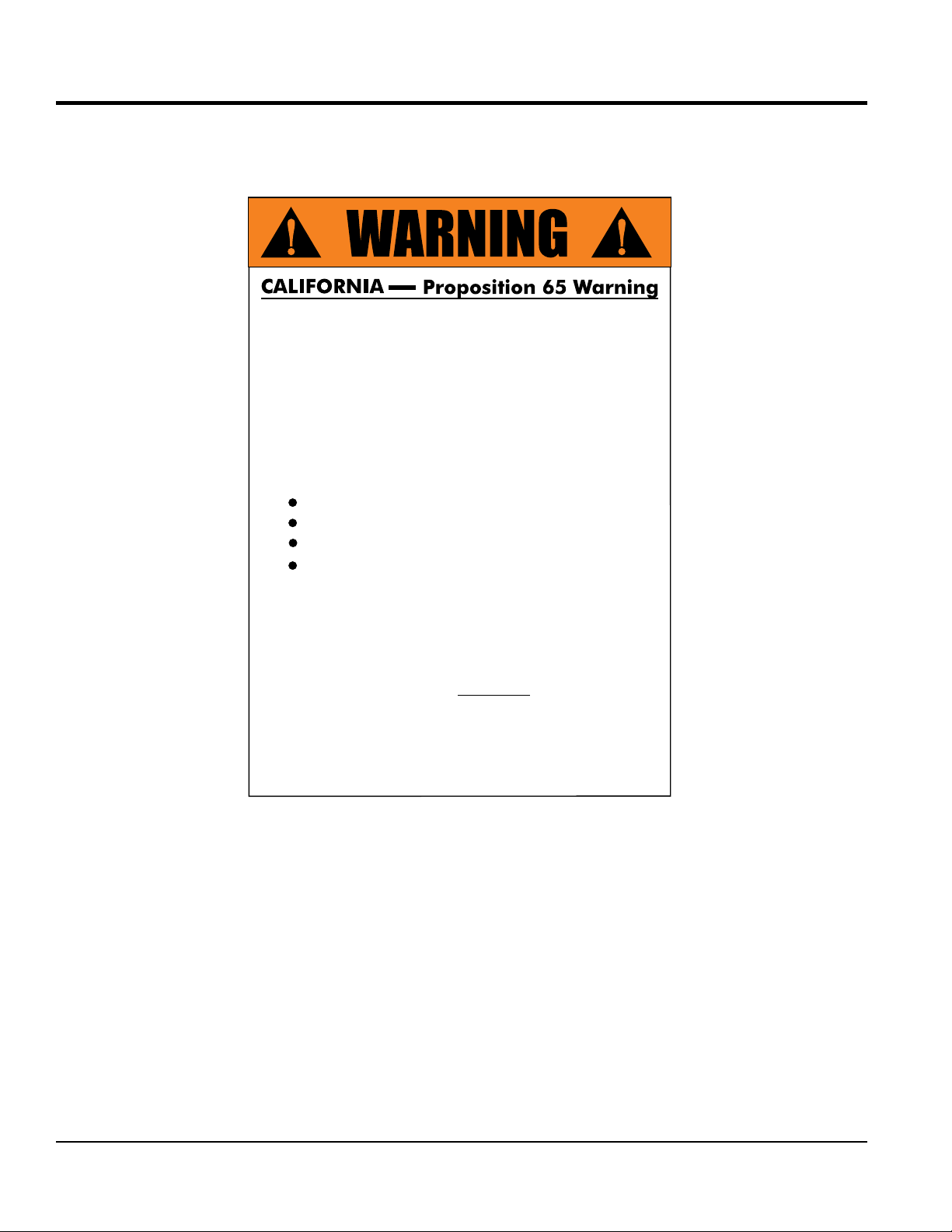
PROPOSITION 65 WARNING
Engine exhaust and some of
its constituents, and some dust created
by power sanding, sawing, grinding,
drillingandotherconstructionactivities
contains chemicals known to the State
of California to cause cancer, birth
defects and other reproductive harm.
Some examples of these chemicals are:
Leadfromlead-basedpaints.
Crystallinesilicafrombricks.
Cementandothermasonryproducts.
Arsenicandchromiumfrom chemically
treatedlumber.
Your risk from these exposures varies,
dependingonhowoftenyoudothistype
of work. To reduce your exposure to
these chemicals: work in aALWAYS
well ventilated area, and work with
approved safety equipment, such as
dust masks that are specially designed
to filter out microscopic particles.
PAGE 2 — TP7X TILE SAW • OPERATION MANUAL — REV. #0 (03/04/11)
Page 3
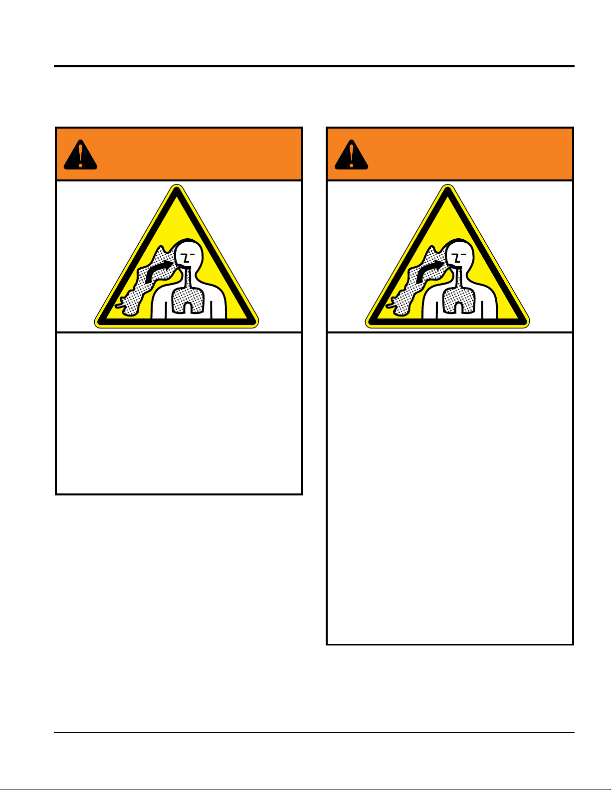
SILICOSIS/RESPIRATORY WARNINGS
WARNING
SILICOSIS WARNING RESPIRATORY HAZARDS
Grinding/cutting/drilling of masonry, concrete, metal and
other materials with silica in their composition may give
off dust or mists containing crystalline silica. Silica is a
basic component of sand, quartz, brick clay, granite and
numerous other minerals and rocks. Repeated and/or
substantial inhalation of airborne crystalline silica can
cause serious or fatal respiratory diseases, including
silicosis. In addition, California and some other
authorities have listed respirable crystalline silica as a
substance known to cause cancer. When cutting such
materials, always follow the respiratory precautions
mentioned above.
WARNING
Grinding/cutting/drilling of masonry, concrete, metal and
other materials can generate dust, mists and fumes
containing chemicals known to cause serious or fatal
injury or illness, such as respiratory disease, cancer,
birth defects or other reproductive harm. If you are
unfamiliar with the risks associated with the particular
process and/or material being cut or the composition of
the tool being used, review the material safety data
sheet and/or consult your employer, the material
manufacturer/supplier, governmental agencies such as
OSHA and NIOSH and other sources on hazardous
materials. California and some other authorities, for
instance, have published lists of substances known to
cause cancer, reproductive toxicity, or other harmful
effects.
Control dust, mist and fumes at the source where
possible. In this regard use good work practices and
follow the recommendations of the manufacturers or
suppliers, OSHA/NIOSH, and occupational and trade
associations. Water should be used for dust
suppression when wet cutting is feasible. When the
hazards from inhalation of dust, mists and fumes cannot
be eliminated, the operator and any bystanders should
always wear a respirator approved by NIOSH/MSHA for
the materials being used.
TP7X TILE SAW • OPERATION MANUAL — REV. #0 (03/04/11) — PAGE 3
Page 4

TP7X Tile Saw
Proposition 65 Warning ........................................... 2
Silicosis/Respiratory Warnings ................................ 3
Table Of Contents .................................................... 4
Safety Information ................................................ 6-9
Specifications ........................................................ 10
Dimensions ............................................................ 11
General Information ............................................... 12
Saw Components ............................................. 14-15
Electric Motor Components/Set-Up ....................... 16
Set-Up ..............................................................17-20
Sawing Guides .............................................20-21
Operation .......................................................... 22-23
Maintenance ..................................................... 24-27
Wiring Diagram (Electric Motor) ............................ 28
Troubleshooting (Blade) ......................................... 30
Troubleshooting (Saw) ........................................... 31
TABLE OF CONTENTS
NOTICE
Specifications are subject to change without notice.
PAGE 4 — TP7X TILE SAW • OPERATION MANUAL — REV. #0 (03/04/11)
Page 5

NOTES
TP7X TILE SAW • OPERATION MANUAL — REV. #0 (03/04/11) — PAGE 5
Page 6
SAFETY INFORMATION
Do not operate or service the equipment before reading
Potential hazards associated with the operation of this
the entire manual. Safety precautions should be followed
at all times when operating this equipment.
Failure to read and understand the safety
messages and operating instructions could
result in injury to yourself and others.
SAFETY MESSAGES
The four safety messages shown below will inform you
about potential hazards that could injure you or others. The
safety messages specifi cally address the level of exposure
to the operator and are preceded by one of four words:
DANGER, WARNING, CAUTION or NOTICE.
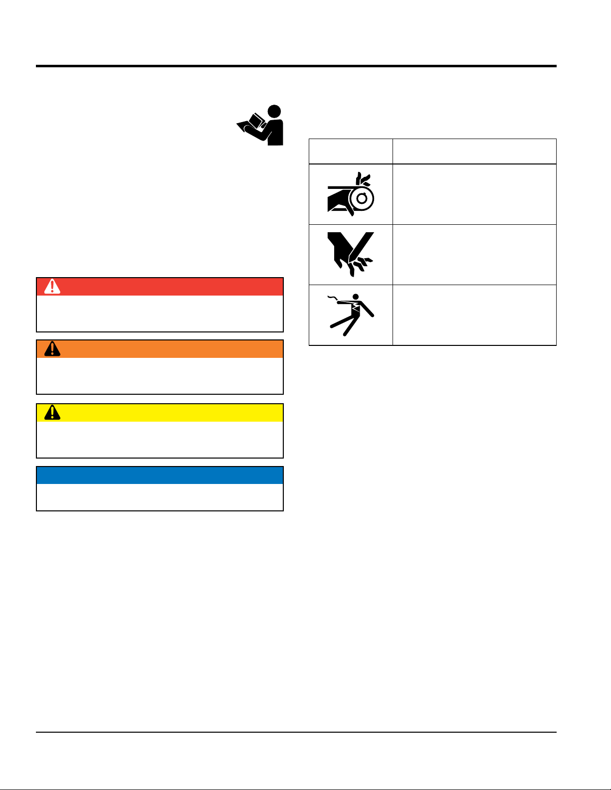
SAFETY SYMBOLS
DANGER
Indicates a hazardous situation which, if not avoided,
WILL result in DEATH or SERIOUS INJURY.
WARNING
Indicates a hazardous situation which, if not avoided,
COULD result in DEATH or SERIOUS INJURY.
equipment will be referenced with hazard symbols which
may appear throughout this manual in conjunction with
safety messages.
Symbol Safety Hazard
Rotating parts hazards
Cutting and crushing hazards
Electric shock hazards
CAUTION
Indicates a hazardous situation which, if not avoided,
COULD result in MINOR or MODERATE INJURY.
NOTICE
Addresses practices not related to personal injury.
PAGE 6 — TP7X TILE SAW • OPERATION MANUAL — REV. #0 (03/04/11)
Page 7
GENERAL SAFETY
NOTICE
This equipment should only be operated by trained and
Whenever necessary, replace nameplate, operation and
accident due to equipment modifi cations. Unauthorized
recommended by Multiquip for this equipment. Damage
keep
Also, know the phone numbers
fi re department.
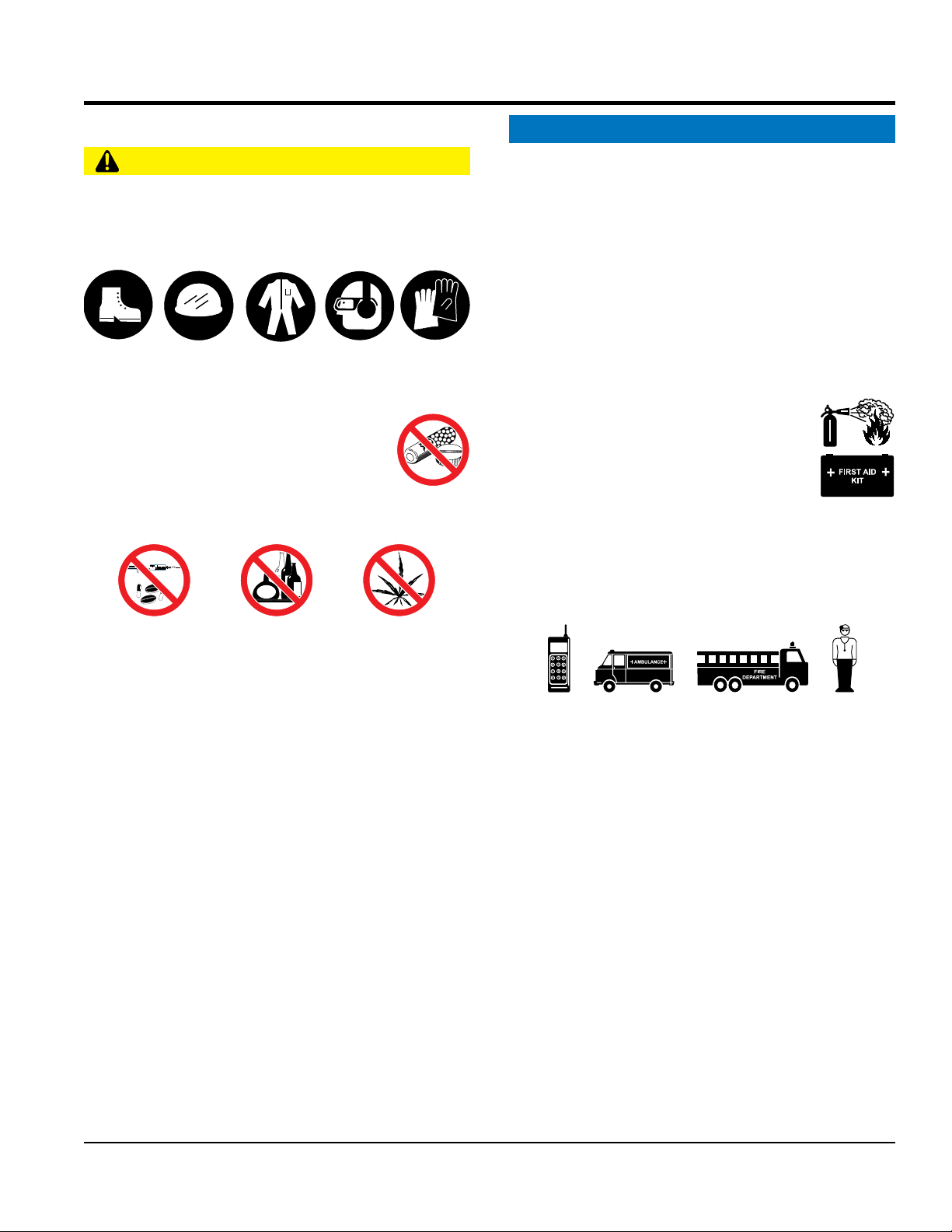
SAFETY INFORMATION
CAUTION
NEVER operate this equipment without proper protective
clothing, shatterproof glasses, respiratory protection,
hearing protection, steel-toed boots and other protective
devices required by the job or city and state regulations.
Avoid wearing jewelry or loose fi tting clothes that may
snag on the controls or moving parts as this can cause
serious injury.
NEVER operate this equipment when not
feeling well due to fatigue, illness or when
under medication.
NEVER operate this equipment under the
infl uence of drugs or alcohol.
ALWAYS clear the work area of any debris, tools, etc.
that would constitute a hazard while the equipment is
in operation.
qualifi ed personnel 18 years of age and older.
safety decals when they become diffi cult read.
Manufacturer does not assume responsibility for any
equipment modifi cation will void all warranties.
NEVER use accessories or attachments that are not
to the equipment and/or injury to user may result.
ALWAYS know the location of the nearest
fi re extinguisher.
ALWAYS know the location of the nearest
fi rst aid kit.
ALWAYS know the location of the nearest phone or
a phone on the job site.
of the nearest ambulance, doctor and
This information will be invaluable in the case of an
emergency.
No one other than the operator is to be in the working
area when the equipment is in operation.
ALWAYS check the equipment for loosened threads or
bolts before starting.
DO NOT use the equipment for any purpose other than
its intended purposes or applications.
TP7X TILE SAW • OPERATION MANUAL — REV. #0 (03/04/11) — PAGE 7
Page 8
SAFETY INFORMATION
SAW SAFETY
RPM) to the recommended blade surface feet per minute
ensure the proper tool has been matched to the material
blade is being
CAUTION
DANGER
NEVER operate the equipment in an explosive atmosphere
or near combustible materials. An explosion or fi re could
result causing severe bodily harm or even death.
WARNING
Accidental starting can cause severe injury
or death. ALWAYS place the ON/OFF
switch in the OFF position.
Keep hands away from moving parts at all
times.
NEVER di sco nne ct any emerg enc y
or safety devices. These devices are
intended for operator safety. Disconnection of these
devices can cause severe injury, bodily harm or even
death. Disconnection of any of these devices will void
all warranties.
CAUTION
ALWAYS ensure saw is securely placed on appropriate
blocks or jackstands when maintenance requires
elevation of the saw.
If the machine malfunctions, stop the saw immediately
and secure it. Fix the problem as soon as possible.
NOTICE
ALWAYS keep the machine in proper running condition.
Fix damage to machine and replace any broken parts
immediately.
Make sure there is no buildup of grease, oil or debris
on the machine.
ALWAYS store equipment properly when it is not being
used. Equipment should be stored in a clean, dry location
out of the reach of children and unauthorized personnel.
BLADE SAFETY
WARNING
NEVER operate the saw without blade
guards and covers in place. Exposure of
the diamond blade must not exceed 180
degrees.
Verify the motor start switch is set to the OFF position
before installing a blade.
A LWAYS in spect blad e be fo re ea ch
use. The blade should exhibit no cracks,
dings, or fl aws in the steel centered core
and/or rim. Center (arbor) hole must be
undamaged and true.
NOTICE
Use proper blades and follow blade manufacturer’s
recommendations. Match the blade RPM (blade shaft
(SFPM).
E n sure t h e bla d e-mou n ting b o l t is ti g htene d
adequately
ALWAYS examine blade flanges for damage and
excessive wear.
Ensure the blade is marked with an operating speed
greater than the spindle speed of the saw.
Only cut the material that is specifi ed for the diamond
blade. Read the specifi cation of the diamond blade to
being cut.
If wet cutting, ensure a WET CUTTING
used and that the water supply system to the blade is
properly functioning and being used.
D O NOT drop the diam ond blade on ground or
surface.
Ensure that the blade is mounted for proper operating
direction.
Adhere to the blade manufacturer’s recommendations
on handling, storage and safe usage of blades.
Rotating blade can cut and crush. ALWAYS
keep hands and feet clear while operating
the saw.
PAGE 8 — TP7X TILE SAW • OPERATION MANUAL — REV. #0 (03/04/11)
Page 9
SAFETY INFORMATION
ELECTRIC MOTOR SAFETY
LIFTING SAFETY
allow any person or animal to stand underneath
Some saws are very heavy and awkward to move around.
Ensure that the diamond blade does not come into contact
transport the saw to or from the job site with the
pour waste, oil or fuel directly onto the ground,
NOTICE
Operate electric motor only at the specifi ed voltage
indicated on the nameplate.
DO NOT spray water onto electric motor.
ALWAYS disconnect AC power plug from power source
before moving saw, changing blade, or performing
maintenance.
ALWAYS make sure the ON/OFF switch
on the electric motor is in the OFF position
when not in use and before inserting the
saw’s power plug into an AC receptacle.
Power Cord/Cable Safety
DANGER
NEVER let power cords or cables lay in water.
NEVER use damaged or worn cables or cords when
connecting equipment to generator. Inspect for cuts in
the insulation.
CAUTION
NEVER
the equipment while lifting.
Use proper heavy lifting procedures.
DO NOT lift machine to unnecessary heights.
NEVER lift the equipment while the motor is running.
TRANSPORTING SAFETY
NOTICE
ALWAYS shutdown motor before transporting.
ALWAYS tie down equipment during transport by
securing the equipment with rope.
with the ground or surface during transportation.
NEVER
blade mounted.
NEVER grab or touch a live power
cord or cable with wet hands. The
possibility exists of electrical shock,
electrocution or death.
Make sure power cables are securely
connected. Incorrect connections may
cause electrical shock and damage to the
saw.
CAUTION
Ensure that cables and cords will not be tripped over or
trapped underneath the saw.
Never use the cable to pull out the plug from the power
source.
NOTICE
ALWAYS make certain that proper power or extension
cord has been selected for the job.
Protect the cable from heat, oil, and sharp edges.
ENVIRONMENTAL SAFETY
NOTICE
Dispose of hazardous waste proper ly.
Examples of potentially hazardous waste
are used motor oil, fuel and fuel fi lters.
DO NOT use food or plastic containers to dispose of
hazardous waste.
DO NOT
down a drain or into any water source.
TP7X TILE SAW • OPERATION MANUAL — REV. #0 (03/04/11) — PAGE 9
Page 10

Table 1. Saw Specifications
SPECIFICATIONS
Model
Blade Capacity
Blade RPM
Arbor Size
Blade Guard
Blade Shaft Bearings
Cutting Head
Conveyor Cart
Drive System
Max. Depth of Cut
Straight Cut
Diagonal Cut
Water Tray
Water Pump
Weight
TP7X
7 in. (178 mm)
6000
5/8 in. (15.875 mm)
Cast Aluminum
Water-Cooled
Cast Aluminum, Adjustable
Aluminum with roller bearings, injected
molded rubber pad, transportation lock
T-belt
1-3/4 in. (44.5 mm)
20 in. (508 mm)
14 in. (356 mm) x 14 in. (356 mm) Size Tile
ABS
115V, 60 Hz — 230 GPH
55 lbs. (25 kg)
Table 2. Electric Motor Specifications
Horsepower
Volts
Amps
Motor RPM
Cycle
Phase
Class
1
115
15
21,500 RPM
60
1
E
PAGE 10 — TP7X TILE SAW • OPERATION MANUAL — REV. #0 (03/04/11)
Page 11

DIMENSIONS
C
A
Figure 1. Dimensions
Table 3. Dimension
Reference Letter Dimensions
A 31.9 in. (811 mm)
B 19.6 in. (49-8 mm)
C 20.4 in. (518 mm)
B
TP7X TILE SAW • OPERATION MANUAL — REV. #0 (03/04/11) — PAGE 11
Page 12

GENERAL INFORMATION
Th e TP7X is a powerful, ro bu st saw design ed to
professionally handle large-sized cuts on ceramics, stone,
and masonry materials. A sturdy steel precision frame and
easily removable ABS water tray provides overall durability
and longevity.
This saw is equipped with a trusted 1 HP electric motor that
operates on standard 115 V power and is designed with
thermal overload and fan air cover protection.
An innovative water-cooled bearing assembly works in
conjunction with the water pump to keep key bearing
components running cooler.
The TP7X saw comes complete with premium blade and
high flow water pump.
DRY CUTTING APPLICATIONS
The TP7X tile saw is shipped from the factory for wet-cutting
saw applications, however it can be used for dry-cutting
saw applications. The most import thing to remember is to
disconnect the water pump. The water pump is cooled by
the flow of water, and failure to disconnect the pump (when
running dry) will cause pump failure.
NOTICE
NEVER have the water pump engaged when dry cutting
applications are involved.
BLADE APPLICATIONS
ACCESSORIES/REPLACEMENT PARTS
If desired, the TP7X tile saw can be equipped with a support
stand. This stand is ideal when the saw needs to be placed
on a secure reliable platform.
FEATURES
Rugged Portable Frame Assembly — Sturdy steel
frame design with handles for easy transport.
Electric Induction Motor — UL/CSA approved 115 V
60 Hz, 1 HP electric motor with thermal overload and
fan cover protection.
Water Tray — Sturdy ABS water tray that is easily
removable for cleaning.
Cutting Table — Rugged cast aluminum table with
heavy-dut y injected molded rubber padding and
extension table. Industrial ball bearing rollers ensure
smooth, precise cart movement.
Water Pump — Powerful submersible pump provides
high volume water flow.
Water-Cooled Blade Shaft Bearing Assembly — High
flow water circulating system designed to keep crucial
bearing components running cooler.
Blade Guard — Hardy cast guard with blade brushes
designed to evenly distribute water to the blade, and to
easily position for blade changes.
This saw has been designed to incor porate the use
of diamond blades as the cutting tool. The optimum
performance of this saw is best evidenced by using 7-inch
(178 mm) diamond blades that match the material being
cut. Ask your dealer, or call Multiquip about your specific
cutting application.
PAGE 12 — TP7X TILE SAW • OPERATION MANUAL — REV. #0 (03/04/11)
Diamond Blade — 7-inch (178 mm) premium tile blade
included.
Page 13

NOTES
TP7X TILE SAW • OPERATION MANUAL — REV. #0 (03/04/11) — PAGE 13
Page 14

SAW COMPONENTS
5
8
4
2
15
1
22
10
7
9
11
12
6
3
13
20
17
18
19
21
16
14
Figure 2. Saw Components
PAGE 14 — TP7X TILE SAW • OPERATION MANUAL — REV. #0 (03/04/11)
Page 15

SAW COMPONENTS
Figure 2 shows the location of the basic components of
the TP7X saw. Listed below is a brief explanation of each
component.
1. AC Power Cord — Plug this cord into a 125 VAC receptacle
when starting of the electric motor is required.
2. V-belt Cover — Remove this cover to access the drive
V-belt. NEVER operate the saw with the V-belt cover
removed
3. Rubber Splash Guard — Keeps water from splashing
from the blade.
4. Electric Motor — This unit uses a 115V, 60 Hz, 1 HP
electric motor.
5. Overcurrent Breaker Button — When a thermal
overload condition exists, press this button to reset the
breaker. Allow time for the electric motor to cool down
before reseting the breaker.
6. Cutting Blade — This unit uses a 7-inch (178 mm)
premium diamond blade. Always use recommended
Multiquip cutting blades. When mounting of the cutting
blade is required, remove the spindle bolt and outside
blade flange. Align cutting blade with inside flange arbor
and reassemble spindle and outside blade flange.
7. Power ON/OFF Switch — To turn on the saw place
in the ON position. Place in the OFF position to shut
down the saw.
8. Water Pump Power Receptacle — Plug the water
pump power cord into this AC receptacle.
9. Blade Guard — Protects the user from the cutting blade.
NEVER operate the saw with the blade guard removed.
10. Blade Guard Adjustment Knob — Turn knob
clockwise to loosen and remove blade guard. Turn
counterclockwise to tighten.
11. Blade Guard Brushes — Prevents foreign matter and
debris from accumulating on the saw blade. Replace brushes
immediately when they become worn or damaged.
12. Cutting Table — Place material to be cut on this rubber
padded table. For ease of cutting, this table has been
placed on rails so that it can easily slide back and forth.
13. Ruler Backstop — When cutting, place material
against backstop. Use measurement rail (ruler) to
determine where material is to be cut.
14. Stopper — Place stopper in water tray when filling
with water.
15. Cutting Head Adjustment Knob — Turn knob
clockwise to loosen and position cutting head to desired
height. Turn counterclockwise to tighten.
16. Water Tray — When wet cutting is required, fill with
clean fresh water. Make sure submersible pump is
totally immersed in water.
17. Electric Water Pump — The electric water pump for
this saw requires 115 VAC. Plug power cord of electric
water pump into AC receptacle located on conduit
box. NEVER run pump dry. Pump must be immersed
in water.
18. Water Lines — Replace the clear vinyl tubing water
lines when they become brittle, worn or clogged. Water
kits are available through your Multiquip dealer.
19. Maintenance Wrench — Use this multi-purpose wrench
when performing maintenance or repairs on the saw.
20. MasterGuide Template Base — Mounts to ruler
backstop to ensures precision while making cuts.
21. Bearing Housing — Houses permanently lubricated ball
bearings to allow motor shaft to rotate smoothly.
22. Metal Frame Handles — There are two carrying
handles on each side of the saw. Grip these handles
when transporting of the the saw is required.
TP7X TILE SAW • OPERATION MANUAL — REV. #0 (03/04/11) — PAGE 15
Page 16

ELECTRIC MOTOR COMPONENTS/SET-UP
CUTTING
ELECTRIC MOTOR COMPONENTS
Figure 3 shows the location of the components of the
electric motor.
115 VAC, 60 Hz
SINGLE -PHASE
ELECTRIC MOTOR
OVERCURRENT
BREAKER BUTTON
ELECTRIC WATER
PUMP AC
RECEPTACLE
Figure 3. Electric Motor Components
ELECTRIC
MOTOR
ON/OFF SWITCH
SAW SET-UP
WARNING
3. Slide water pump onto U-shaped bracket located at
the bottom of the frame. See Figure 6.
4. Slide cutting head onto the post. Secure cutting head
to the shaft using provided flat washer, lock washer and
nut. Attach cutting depth control knob and washers to
the cutting head through the slot located underneath
the belt guard. See Figure 4.
5. Mount blade guard onto shaft protruding from the side
of the cutting head. Secure the blade guard in place
using the provided serrated washer and blade guard
knob.
HEAD
BLADE
GUARD
KNOB
BLADE
SHAFT
CUTTING
DEPTH
CONTROL
KNOB
WATER
TRAY
GUARD
Whenever cleaning, adjusting or lubricating any part
of the saw, make certain to place the power ON/OFF
switch in the OFF position and disconnect the plug from
the power source.
1. Open the shipping container carefully, lift the saw by
its carrying handles and place it on a suitable table or
platform. Make sure the table or platform can support
the weight of the saw.
2. Make sure that the following items are found in the
container:
Saw
Water Tray
Drain Plug
Universal Wrench
Saw Blade
Water Pump
Owner’s Manual
MasterGuide Template
Base
Figure 4. Saw Assembly
6. If using the optional support stand, assemble as
described in the Suppor t Stand Assembly section.
Make sure that the saw is secured on the support
stand as instructed.
SUPPORT STAND ASSEMBLY (OPTIONAL)
Refer to Figure 5 for location of components.
1. Remove the folding stand from its box.
2. Swing the working bench upright. Open the two legs
and place the work bench on top of the folding stand.
3. After teh saw stand is assembled, seat the saw
securely on top of the stand.
PAGE 16 — TP7X TILE SAW • OPERATION MANUAL — REV. #0 (03/04/11)
Page 17

SET-UP
BEARING
HOUSING
6. Insert the water pump power plug into the outlet receptacle
on the electric motor conduit box as shown in Figure 7.
ELECTRIC MOTOR
CONDUIT BOX
POWER
PLUG
ELECTRIC WATER
PUMP AC
RECEPTACLE
WATER
PUMP
Figure 5. Support Stand Assembly
CONNECTING THE WATER PUMP
Refer to Figure 6.
1. Place the pump into the middle of the water tray along
its side so that the water outlet is positioned horizontally.
2. Attach the water hose coming from the blade guard
and bearing housing to the water pump.
3. Install drain plug in water tray.
4. Fill the water tray with clean fresh water. The water
pump intake must always be fully covered by water.
Also, keep the pump intake free of sludge, debris and
other materials that may accumulate in the tray.
5. Make certain that the water hose will not come in contact
with the blade or interfere with any moving parts.
BLADE
WATER
PUMP
WATER
HOSES
GUARD
Figure 7. Water Pump Power Connection
WARNING
Disconnect the pump before attempting to handle the
pump. NEVER operate pump without water in the tray.
NOTICE
The above procedure is for wet cutting applications only.
NEVER dry cut with the pump connected to an AC power
source. Running the pump dry will damage the pump.
ALWAYS disconnect the pump’s power cord when dry cutting.
DRAIN
PLUG
Figure 6. Connecting the Water Pump
TP7X TILE SAW • OPERATION MANUAL — REV. #0 (03/04/11) — PAGE 17
Page 18

SET-UP
MAX.RPM
SPECIFICATIONS
1
2
3
4
5
6
7
BLADES
WARNING
Failure to thoroughly inspect the blade for
operational safety could result in damage to
the blades or the saw and may cause serious
injury to the user or others in the operating
area. Inspect the blade flanges and shaft for
damage before installing the blade.
Blade Components
Diamond blades are recommended for your saw. Ask your
Multiquip dealer about your specific cutting application.
Figure 8 highlights the components of a diamond blade.
3. Directional Arrow — Check to ensure that the blade is
oriented properly on the spindle for sawing. Reference the
directional arrow on the blade and place it so the direction
of rotation “downcuts” with the turn of the shaft.
4. Diamond Segment or Rim — Ensure that there are
no cracks, dings, or missing portions of the diamond
segment/rim. DO NOT use a blade that is missing
a segment or a portion of the rim. Damaged and/or
missing segments/rims may cause damage to your saw
and injury to the user or others in the operating area.
5. Specifications — Ensure that the blade specifications,
size, and diameter properly match up to the sawing
operation. Wet blades must have water to act as a coolant.
Utilizing a diamond blade not matched properly to the task
may result in poor performance and/or blade damage.
6. Arbor Hole — It is essential that the arbor hole
diameter properly matches the shaft arbor, and that it
is free from distortions. Correct blade flanges (collars)
must be used. The inside face of the flanges must be
clean and free of debris. An out of round arbor condition
will cause damage to the blade and the saw.
7. MAX RPM — This RPM reference is the maximum safe
operating speed for the blade selected. NEVER exceed
the max RPM on the diamond blade. Exceeding the MAX
RPM is dangerous, and may cause poor performance
and may damage the blade. All blades used must be
designed for the maximum spindle RPM.
Cutting Depth
Figure 8. Diamond Blade
1. Stress Relief Holes (Gullets) — Check the steel core
for cracks that may have propagated from the slots
and/or gullets. Cracks indicate extreme fatigue failure
and if sawing continues, catastrophic failure will occur.
2. Edge of the Steel Core — Check the diameter edge for
discoloration (blue oxidation) indicating an overheating
condition caused by insufficient cooling water/air.
Overheating of blades may lead to loss of core tension
and/or increase the possibility for blade failure. Check
to make sure the steel core’s width is uniform about
the rim of the blade, and not succumbing to an “under
cutting” condition brought about by highly abrasive
material or improper under cutting core protection.
PAGE 18 — TP7X TILE SAW • OPERATION MANUAL — REV. #0 (03/04/11)
The recommended cutting depth is 1/4" (6 mm) below the
cutting table surface. To adjust the cutting depth, loosen the
cutting head adjustment knob so that the blade is 1/4" below
the top of the cutting table's surface. See Table 4 to determine
cutting depth by blade diameter.
WARNING
Setting the blade too low may damage the cutting table
and if set too high, the blade may grab the material
being cut, causing damage and possibly injury.
Table 4. Blade Diameter vs. Cutting Depth
Blade Diameter Cutting Depth
7 in. (178 mm) 1-3/4 in. (44.5 mm)
Page 19

SET-UP
Blade Installation
Refer to Figure 9 and the following instructions for installing
the blade.
1. Loosen blade guard adjustment knob located at the
rear of the blade guard. Carefully raise the cutting
head to its highest position and secure it into place by
tightening the blade guard adjustment knob.
2. Remove the blade shaft nut and outer flange. If a blade
has been mounted, hold the blade with one hand and
use the other hand to loosen the nut with the universal
wrench. Remove existing blade.
3. Mount new blade, but make certain the arrow on the
blade coincides with the rotation direction of the shaft.
Ensure the capacity of the blade guard matches the
diameter of your cutting blade.
4. Attach outer flange and blade shaft nut. Hold the blade
with one hand and use the other hand to tighten the
nut with the universal wrench. Make certain the flanges
are pressed flush against the blade and that the nut is
firmly tighthened, but DO NOT over tighten.
5. Loosen blade guard adjustment knob, lower the blade
guard, and retighten the knob.
6. Slightly loosen the cutting head adjustment knob, lower
the cutting head so that the blade is 1/4" (6 mm) below
the surface of the cutting table. Tighten the adjustment
knob firmly to hold the cutting head in place.
BLADE
GUARD
ADJUSTMENT
BLADE
GUARD
BLADE
SHAFT
KNOB
INNER
FLANGE
BLADE
BLADE
SHAFT
NUT
OUTER
FLANGE
Figure 9. Blade Installation
See Table 5 for proper blade use guidelines.
Table 5. Proper Blade Use
Dos Don’ts
Inspect blades daily for cracks or uneven wear. Do not operate the saw without safety guards in place.
Always use appropriate blades for material being cut.
Inspect arbor shaft for uneven wear before mounting
blade.
Always use blades with the correct arbor shaft size.
Ensure that blade is mounted in the correct
direction.
Use proper safety equipment when operating the saw.
Always have a continuous flow of water on both
sides of blade.
Secure the blade to the arbor with a wrench. Do not attempt to cut a radius or curve.
Inspect segment blades for segment cracking or loss. Do not cut too deep or too fast into the material.
Do not use damaged blades.
Do not operate the saw with blades larger than 7 in.
(178 mm)
Do not cut dry with blades marked “Use Wet”.
Do not exceed manufacturer’s recommended
maximum RPM.
Do not force blade into material. Let blade cut at its
own speed.
Do not make long cuts with dry blades. Allow them
to air cool.
Do not use the edge or side of blade to cut or grind.
Do not cut any material not recommended by blade
manufacturer.
TP7X TILE SAW • OPERATION MANUAL — REV. #0 (03/04/11) — PAGE 19
Page 20

SET-UP/SAWING GUIDES
CONNECTING THE POWER
1. Place the power ON/OFF switch (Figure 10) in the OFF
position (down).
2. Connect an extension cord of adequate current carrying
capacity to the power plug on the electric motor.
3. MAKE CERTAIN that the correct size extension cord
is used. Undersized wires will burn out motors. Use
Table 6 to determine the correct extension cord size.
Table 6. Extension Cord Sizes
50 ft
(15. 2 m)
Long
Motor
Voltage
VAC
25 ft
(7.6 m)
Long
1 HP 115 No. 12 No. 10 No. 8
115 VAC, 60 Hz
SINGLE -PHASE
ELECTRIC MOTOR
OVERCURRENT
BREAKER BUTTON
75 ft
(22.9 m)
Long
4. Plug the free end of the extension cord into an AC power
receptacle. Whenever possible use a GFCI receptacle
(Figure 11) to reduce the risk of electrical shock.
Figure 11. GFCI Receptacle
SAWING GUIDES
Using the Cutting Table
The ruler guide has inches and centimeters marked
along the top to allow convenient measurements and to
promote precision cuts. See Figure 12.
A rip guide should be used with the cutting table to ensure
precision while making cuts.
ELECTRIC
MOTOR
ON/OFF SWITCH
CONNECT TO
115/230 VAC
POWER SOURCE
EXTENSION
CORD
ELECTRIC WATER
PUMP AC
RECEPTACLE
Figure 10. Extension Cord Connection
DANGER
NE VE R grab or tou ch a live
power cord with wet hands, the
possibility exists of electrical shock,
electrocution, and even death!
NEVER use a damaged or worn
extension cable when connecting
to a power source. Defective cables may cause damage
to the saw’s electric motor or electrical shock.
ALWAYS use a grounded (3-wire) extension cord
and MAKE CERTAIN that the motor is connected to
a properly grounded electric circuit. If possible use a
ground fault circuit interrupter to protect the operator
from possible electric shock.
MASTERGUIDE
TEMPLATE BASE
ADJUSTABLE
RULER GUIDE
OPTIONAL
RIP GUIDE
Figure 12. Cutting Table
Using the MasterGuide Template Base
1. Set the template base (Figure 12) by positioning it
on the desired dimension on the cutting table and
tightening the universal clamp to the table. Make sure
that the template base is firmly tightened. The template
base can be used for 90° rip cuts from both the left and
right side. The 45° diagonal cuts are quickly achieved
with the specially designed fitted notches on the
template base of 4", 6", 8" and 10"~14" tiles (Note the
specifically shown dimensions on each notch).
PAGE 20 — TP7X TILE SAW • OPERATION MANUAL — REV. #0 (03/04/11)
Page 21

2. After the template base is positioned for the desired
rip cut, place material flat against either side of the
template base at the desired measurement.
Using the Rip Guide
1. Set the rip guide (Figure 12) at the desired location on
the ruler guide and tighten the threaded knob. Make
sure that the rip guide is firmly tightened to avoid
slippage. The rip guide can be used for 45° and 90°
cuts.
2. After the rip guide is positioned, for the desired cut,
place material flat against the rip guide and ruler guide.
3. Now you are ready to make your cut.
Performing Diagonal Cuts
1. Place the corner of the material in the open slot of the
measurement rail and adjust the template base to fit
the correct tile size.
SAWING GUIDES
2. Line up the material being cut with the appropriate
pre-marked lines on the cutting table.
3. Now you are ready to make your cut.
Performing Miter Cuts
Use the miter block to make miter cuts. See Figure 13.
1. Place the lip of the miter block on the ruler guide with
the threaded knob facing you.
2. Position the miter block such that a tile laying flat
against the block may rest its left-most edge within
the vertical channel of the cutting table. Tighten the
threaded knob to secure the miter block in place.
3. Place material onto miter block and you are ready to cut.
Figure 13. Miter Block
TP7X TILE SAW • OPERATION MANUAL — REV. #0 (03/04/11) — PAGE 21
Page 22

OPERATION
START-UP PROCEDURE
NOTICE
Read and fully understand this manual before
starting or attempting to operate the saw.
Before starting the saw’s electric motor
make sure that the Safety, General Information, and
Set-Up sections have been completed and understood.
DO NOT proceed until the above mentioned sections
have been completed.
NOTICE
ALWAYS use the water feed system unless special dry
cut blades are being used. If dry cutting is required,
disconnect water pump.
WARNING
ALWAYS wear approved eye and hearing
protection before operating the saw.
WARNING
NEVER lift the blade guard while the blade
is rotating. The possibility exists of severe
bodily harm if fingers or hands come in
contact with the rotating saw blade. Wait
for the blade to stop rotating before lifting
the blade guard.
1. Place the material to be cut (Figure 14) on the cutting
table against the backstop.
CUTTING
TABLE
MATERIAL
BACKSTOP
WARNING
NEVER place hands or feet inside the belt
guard or blade guard while the motor is
running. ALWAYS shut the motor down before
performing any kind of maintenance
WARNING
NEVER place hands and fingers near
the cutting blade. The possibility exists of
severe bodily harm if hands and fingers
come in contact with rotating saw blade.
WARNING
ALWAYS ensure that the cutting blade has
been mounted correctly.
DANGER
NEVER touch a live power cord with wet
hands. The possibility exists of electrical
shock, electrocution which could cause
severe bodily harm, even death.
Figure 14. Material Placement
DANGER
ALWAYS be alert to the fact that there is a rotating
blade on the saw and be extremely aware of your body
position — especially your hands in relationship to the
rotating blade. The possibility exists of severe bodily
harm or even death if your body comes in contact with
the rotating saw blade.
2. Turn the power ON/OFF switch (Figure 15) to the ON
position with the blade away from the material to be
cut, the cutting blade should begin to rotate. Before
cutting remember to follow all safety rules referenced
in this manual.
Figure 15. Power ON/OFF Switch (ON)
PAGE 22 — TP7X TILE SAW • OPERATION MANUAL — REV. #0 (03/04/11)
Page 23

3. Push the cutting table with the material, slowly and
evenly until the cut is complete. Move the cutting table
back and remove the cut pieces.
4. Avoid overloading the motor when cutting. However,
the electric motor is protected with a manual-reset
thermal overload switch that will turn the saw off if the
motor is overheated. In the event that the switch is
tripped, turn the “ON/OFF” switch to the “OFF” position
and allow the motor to cool before attempting to restart.
SHUT DOWN PROCEDURE
1. Place the power ON/OFF switch (Figure 16) in the OFF
position (down).
OPERATION
Figure 16. Power ON/OFF Switch (OFF)
2. Wait for the cutting blade to stop rotating.
3. Disconnect the saw's AC power cord from the power
source. NEVER leave the saw connected to a power
source when unattended. This will prevent accidental
starting.
4. Using a soft cloth, clean any excess debris or residue
that may have accumulated on the saw.
5. Store saw in a clean dry location where it will be out
of the reach of children.
TP7X TILE SAW • OPERATION MANUAL — REV. #0 (03/04/11) — PAGE 23
Page 24

MAINTENANCE
A good preventive maintenance program of regular
inspection and care will increase life and improve the
performance of the saw and cutting blades.
WARNING
Whenever cleaning, adjusting, or lubricating any part of
the saw, MAKE CERTAIN to do the following:
• Place power ON/OFF switch to the OFF position.
• Disconnect power cord from AC source.
• NEVER attempt to check the V-belt with the engine
running. Severe bodily injury can occur.
BASIC MAINTENANCE
1. Tighten loose nuts or screws and replace any cracked
or broken parts.
2. Clean the machine frequently. DO NOT use aggressive
cleaners (i.e. containing solvents). DO NOT use high
high-pressure water jets, aggressive detergents or
solutions and liquids with a temperature exceeding
86°. Use a fluff-free cloth only. Use a cloth which may
be lightly moistened only for removing dust and dirt.
Hard packed dirt can be removed with a soft brush.
5. After each day's use, run clean water through the
water pump and water hoses. This extends pump and
blade life.
6. After cleaning, remove all covers and adhesive tape. All
screws or nuts which may have been loosened must
be retightened.
7. Check the spindle bolt for tightness periodically.
8. Keep the drive belt tight. It is very important to replace
worn belts as soon as possible. To adjust belt tension,
loosen the four (4) motor mounting bolts and remove
the belt guard. Tighten the adjusting nut on the back
of the motor plate to increase the tension. Proper belt
tension is 4-5 lbs. of force with approximately 3/16" of
belt deflection measured at a point midway between the
pulleys. Tighten the motor mounting bolts and reattach
the belt guard.
9. MAKE CERTAIN that the cutting head is aligned
properly. Misalignment can adversely affect blade life.
10. The blade flanges must have a diameter of 4".
Undersized flanges will reduce blade life and cause
breakage. Therefore, they should be replaced at
once.
DO NOT let any water/cleaning liquid/vapor penetrate
into the electric motor, connectors/plugs, switches, etc.
Cover all apertures, holes in the housing, connectors
or plugs, etc, or seal them with adhesive tape.
Use a soft, low-pressure water jet and a brush to rinse
dirt and incrustations away. Be particularly careful when
near hazardous par ts of the machine (e.g. switch,
motor). Clean the motor and switches only by wiping
with a moist cloth.
3. Remove the belt guard and clean the pulleys. The belts
and pulleys will wear rapidly if excessive dust builds up.
4. Clean the sludge that accumulates on the bottom of
the water tray at least once a day and refill with clean
water. It may be necessary to clean the tray out twice
a day in heavy cutting. The sludge is abrasive and will
shorten the life of the water pump and blades.
11. Cutting blades must fit the arbor snugly. This is very
important with diamond blades as pounding will occur
and serious blade damage can result. If the arbor
shoulder of the inner blade flange is grooved from blade
slippage, the flange must be replaced.
12. Inspect the cutting table periodically. Replace worn
parts.
13. DO NOT “rinse” the bearings of the drive elements to
prevent them from running dry. The ball bearings of the
machine are permanently lubricated.
14. Replace the spindle bearings as soon as they begin to
make any strange noises. Worn bearings can destroy
blades very quickly.
15. Grease pivot bearings periodically.
PAGE 24 — TP7X TILE SAW • OPERATION MANUAL — REV. #0 (03/04/11)
Page 25

MAINTENANCE
MAINTENANCE INTERVALS
Use the following guidelines to perform maintenance on
your saw.
After every use of the machine
Remove dirty water from container.
Remove dirt and mud from the bottom of the container.
Rinse the immersion pump with fresh water to prevent
water pump clogging from residual dirt.
After wet cleaning and before using the machine
again
Connect the machine to an electric power outlet
equipped with a “GFCI” safety power breaker. If the safety
power breaker cuts off the electrical power supply, do
not try to operate the machine but have it checked by
an authorized dealer first.
Before not using the machine for a prolonged
period of time
Clean and lubricate all movable parts. DO NOT grease
guide rails.
Check that the immersion pump works properly. Turn
on the cooling water tap and switch the machine on. If
the pump does not give any water or only a little, switch
the machine off at once. Clean the pump, or replace if
necessary.
Ambient temperature below 32°F / 0°C (operation
in winter)
To prevent the water in the pump and cooling system
from freezing, remove the water after using the machine
or when there will be a long break. Make sure that the
cooling system is entirely drained so that there is no
water left inside the pump and water hose.
CLEANING THE WATER TRAY
Refer to Figure 17.
Lift the saw up from inside the water tray.
1. Remove the drain plug and drain any water left inside
the water tray.
2. Flush water into tray while holding it upright to remove
any sludge buildup.
3. Replace the saw back into the water tray.
After not using the machine for a prolonged period
of time
Check that the stand is safely fixed.
Check that all screw joints and nuts are fixed.
Check that the cutting table is seated properly on the
guide rails and that it easily moves along the entire
length of the rails.
With the saw blade removed, switch on the motor for an
instant and switch it off again. If the motor does not run,
have the machine inspected by a qualified electrician.
Figure 17. Water Tray Removal
TP7X TILE SAW • OPERATION MANUAL — REV. #0 (03/04/11) — PAGE 25
Page 26

MAINTENANCE
WATER PUMP MAINTENANCE
When the machine has not been used for a long period of
time, hard packed dirt may build up inside the pump and
block the pump wheel.
NOTICE
If the machine is activated with the immersion pump
blocked, the electric motor will be damaged within a
few minutes!
Please follow the steps below to clean the pump before
operating the saw.
1. Remove the immersion pump from the water container.
2. Clean the immersion pump.
3. Loosen the fixing screws of the pump lid.
4. Take the lid off the pump (be careful not to damage or
lose the gasket underneath)
5. Clean the pump lid.
7. To reassemble, follow steps in reverse order.
Figure 18. Belt Replacement
CUTTING HEAD REMOVAL
To remove the cutting head, see Saw Set-Up and Figure 4
and perform the steps in reverse.
6. Remove all dirt and incrustations from the pump wheel.
7. Check whether the pump wheel can be easily turned.
8. Reassemble the immersion pump and check that it
works properly.
BELT REPLACEMENT
To replace the belt (Figure 18) perform the following.
1. Turn off and unplug the saw.
2. Loosen and remove the belt guard sccrews and take
off the belt guard.
3. Loosen the 6 nuts on the cutting head’s supporting arm.
4. Leave the blade in position, and use your hand to hold
the blade shaft tightly. Now loosen the pulley lock screw
on the rear of the motor pulley shaft.
5. Carefully loosen the pulley and belt outward slightly,
so there is a little slack in the belt.
6. Take off the old belt and replace with a new one.
BEARING HOUSING REMOVAL
To remove the bearing housing (Figure 19), perform the
following:
1. Follow steps 1-6 of the Belt Replacement Section.
2. Remove the blade lock nut and remove the blade (if
there is one present.)
3. Remove the precaution label and loosen the 4 screws
at the front of the cutting head. Remove the bearing
housing and inner flange.
PAGE 26 — TP7X TILE SAW • OPERATION MANUAL — REV. #0 (03/04/11)
Page 27

Figure 19. Bearing Housing Removal
MAINTENANCE
BEARING HOUSING INSTALLATION
To install a new bearing housing, perform the following:
1. Make sure that the old housing has been properly
removed.
2. Unpack the new bearing housing and place the flat
portion face-down on a towel situated on a flat surface.
3. Secure the cutting head in a in a completely horizontal
position.
4. Slide the new bearing housing with the flat portion
facing upwards onto the 4 screws located below the
mounting plate. Take care not to damage the inner
flange. Lock the bearing housing into place by using
the brackets and nuts.
5. Pull the motor towards you, place the belt on the
pulleys, and tighten the motor position adjustment
screw. Be sure to leave some slack on the belt.
6. Align the belt by adjusting the motor pulley after
loosening the hex screw.
WARNING
Do not adjust the bearing housing pulley.
7. After aligning the belt, tighten the hex screw.
8. Replace the belt guard and lock into place using 4 screws.
TP7X TILE SAW • OPERATION MANUAL — REV. #0 (03/04/11) — PAGE 27
Page 28

WIRING DIAGRAM (ELECTRIC MOTOR)
White
Black
Green
Power Outlet for Water Pump
Power Cable
Green
Green
Black Black
Switch
White
Wiring Box
Figure 20. Electric Motor Wiring Diagram
Motor
Overcurrent
White
Black
WhiteWhite
Breaker
PAGE 28 — TP7X TILE SAW • OPERATION MANUAL — REV. #0 (03/04/11)
Page 29

NOTES
TP7X TILE SAW • OPERATION MANUAL — REV. #0 (03/04/11) — PAGE 29
Page 30

TROUBLESHOOTING (BLADE)
Table 7. Blade Troubleshooting
Symptom Possible Problem Solution
Irregular run of the saw blade Poor tension in the blade material Return saw blade to manufacturer
Have the saw blade aligned/flattened
Chean the receiving flange
Replace saw blade.
Replace saw blade.
Use appropriate type of saw bladeSaw blade type is unsuitable for the machine
Arbor of the saw blade must be fitted with an
appropriate adapter ring
Check the receiving flange and have it
replaced if necessary
Ensure optimum flow of cooling water
The material feed is too high; proceed more
slowly
Ensure that the direction of the feed is
absolutely parallel to the saw blade
Adjust roller table
The material feed is too high; proceed more
slowly
Saw blade wobbles when running
Diamond segment becomes loose
Excessive wear
Cracks in or near diamond segment
Saw blade is blunt
Appearance of cut is not optimal
Center hole in saw blade has become wider
due to wear
Saw blade shows blooming colors
Grinding marks on the saw blade
Saw blade is damaged or bent
Flange of the saw blade is damaged Replace the saw blade flange
Shaft of the motor is bent Replace the electric motor
Overheating of the saw blade; cooling water
not sufficient
Wrong type of saw blade Use harder saw blade
Shaft of motor causes wobbling Have motor or bearings of motor replaced
Overheating Ensure optimum flow of cooling water
Saw blade too hard Use softer blade
Fixed flange is worn out Have fixed flange replaced
Motor shaft bearing Replace the bearing of the motor shaft
Saw blade type is unsuitable for the material
being cut
performance
Saw blade too hard
Diamond segments are blunt Replace saw blade.
Poor tension in the blade material Return saw blade to manufacturer
Too much load placed on saw blade Use a suitable saw blade
Diamond segments are blunt Replace saw blade.
Saw blade has slipped on the motor shaft
when running
Saw blade overheating due to lack of cooling
water
Lateral friction when cutting
Material is not being fed parallel to saw blade
Poor tension in blade material Have the saw blade tensioned
Too much load on the saw blade
PAGE 30 — TP7X TILE SAW • OPERATION MANUAL — REV. #0 (03/04/11)
Page 31

Symptom Possible Problem Solution
Machine does not run when switched on
Motor stops (power cuts out)
Poor machine performance, little power
Insufficient flow of cooling water or no cooling
water at all
TROUBLESHOOTING (SAW)
Table 8. Saw Troubleshooting
Power cord not properly fixed/plugged in
Power cord defective
Main power switch defective
Loose electrical connection inside the electric
system
Motor defective
Too much pressure exerted while cutting Exert less pressure when cutting
Incorrect specification for saw blade
Saw has a defective electric system
Power cord/extension cable too long or cable
still wound up inside cable drum
Power network is insufficient
Drive motor no longer runs at rated speed
(RPM)
The water pump draws air Fill the water tray with water
Filter clogged Clean the filter of the water pump
Pump wheel of the immersion pump is
blocked by dirt
Check that the machine is properly
connected to the power supply
Have the power cord checked, replace if
necessary
Have the main power switch checked and
replaced if necessary by a qualifed electrician
Have the whole electric system of the
machine checked by a qualified electrician
Have the motor checked and replaced if
necessary by a qualified technician
Use a saw blade which corresponds to the
material being cut
Have the electric system of the saw checked
by a qualified technician
Use a power cord/extension cable of the
rated length, use a cable drum with cable
fully extended
Observe the electrical ratings of the machine
and connect it only to a power network which
complies with these ratings
Have the motor checked by a qualified
electrician and replace if necessary
Disassemble the immersion pump and clean it
TP7X TILE SAW • OPERATION MANUAL — REV. #0 (03/04/11) — PAGE 31
Page 32

OPERATION MANUAL
HERE’S HOW TO GET HELP
© COPYRIGHT 2011, MULTIQUIP INC.
Multiquip Inc
the MQ logo are registered trademarks of Multiquip Inc. and may not be used, reproduced, or altered without written permission. All other trademarks are the property
The information and specifications included in this publication were in effect at the time of approval for printing. Illustrations, descriptions, references and technical data contained in
this manual are for guidance only and may not be considered as binding. Multiquip Inc. reserves the right to discontinue or change specifications, design or the information published
in this publication at any time without notice and without incurring any obligations.
PLEASE HAVE THE MODEL AND SERIAL
NUMBER ON-HAND WHEN CALLING
United StateS
Multiquip Corporate Office MQ Parts Department
18910 Wilmington Ave.
Carson, CA 90746
Contact: mq@multiquip.com
Service Department Warranty Department
800-421-1244
310-537-3700
Technical Assistance
800-478-1244 Fax: 310-943-2238
Tel. (800) 421-1244
Fax (800) 537-3927
Fax: 310-537-4259 800-421-1244
800-427-1244
310-537-3700
310-537-3700
Fax: 800-672-7877
Fax: 310-637-3284
Fax: 310-943-2249
mexico United Kingdom
MQ Cipsa Multiquip (UK) Limited Head Office
Carr. Fed. Mexico-Puebla KM 126.5
Momoxpan, Cholula, Puebla 72760 Mexico
Contact: pmastretta@cipsa.com.mx
Tel: (52) 222-225-9900
Fax: (52) 222-285-0420
Unit 2, Northpoint Industrial Estate,
Globe Lane,
Dukinfield, Cheshire SK16 4UJ
Contact: sales@multiquip.co.uk
Canada
Multiquip
4110 Industriel Boul.
Laval, Quebec, Canada H7L 6V3
Contact: jmartin@multiquip.com
Tel: (450) 625-2244
Tel: (877) 963-4411
Fax: (450) 625-8664
Tel: 0161 339 2223
Fax: 0161 339 3226
of their respective owners and used with permission.
This manual MUST accompany the equipment at all times. This manual is considered a permanent part of the equipment and should remain with the unit if resold.
and
Your Local Dealer is:
 Loading...