

Page 1

OPERATION AND PARTS MANUAL
MODEL TP24
TILE SAW
(ELECTRIC MOTOR)
Revision #2 (04/12/12)
To find the latest revision of this
publication, visit our website at:
www.multiquip.com
THIS MANUAL MUST ACCOMPANY THE EQUIPMENT AT ALL TIMES.
Page 2
PROPOSITION 65 WARNING
Engine exhaust and some of
its constituents, and some dust created
by power sanding, sawing, grinding,
drillingandotherconstructionactivities
contains chemicals known to the State
of California to cause cancer, birth
defects and other reproductive harm.
Some examples of these chemicals are:
Leadfromlead-basedpaints.
Crystallinesilicafrombricks.
Cementandothermasonryproducts.
Arsenicandchromiumfrom chemically
treatedlumber.
Your risk from these exposures varies,
dependingonhowoftenyoudothistype
of work. To reduce your exposure to
these chemicals: work in aALWAYS
well ventilated area, and work with
approved safety equipment, such as
dust masks that are specially designed
to filter out microscopic particles.
PAGE 2 — TP24 TILE SAW • OPERATION AND PARTS MANUAL — REV. #2 (04/12/12)
Page 3
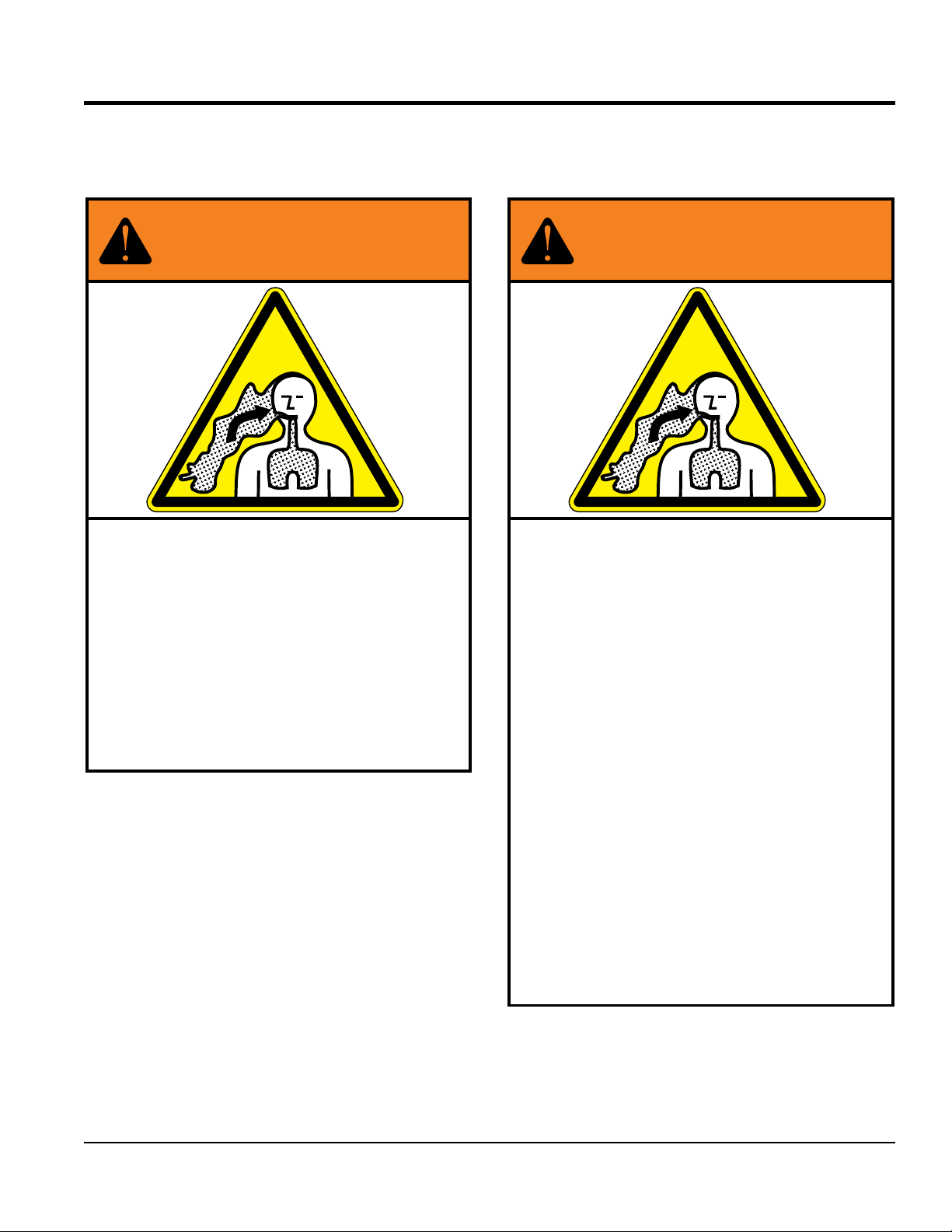
SILICOSIS/RESPIRATORY WARNINGS
WARNING
SILICOSIS WARNING RESPIRATORY HAZARDS
Grinding/cutting/drilling of masonry, concrete, metal and
other materials with silica in their composition may give
off dust or mists containing crystalline silica. Silica is a
basic component of sand, quartz, brick clay, granite and
numerous other minerals and rocks. Repeated and/or
substantial inhalation of airborne crystalline silica can
cause serious or fatal respiratory diseases, including
silicosis. In addition, California and some other
authorities have listed respirable crystalline silica as a
substance known to cause cancer. When cutting such
materials, always follow the respiratory precautions
mentioned above.
WARNING
Grinding/cutting/drilling of masonry, concrete, metal and
other materials can generate dust, mists and fumes
containing chemicals known to cause serious or fatal
injury or illness, such as respiratory disease, cancer,
birth defects or other reproductive harm. If you are
unfamiliar with the risks associated with the particular
process and/or material being cut or the composition of
the tool being used, review the material safety data
sheet and/or consult your employer, the material
manufacturer/supplier, governmental agencies such as
OSHA and NIOSH and other sources on hazardous
materials. California and some other authorities, for
instance, have published lists of substances known to
cause cancer, reproductive toxicity, or other harmful
effects.
Control dust, mist and fumes at the source where
possible. In this regard use good work practices and
follow the recommendations of the manufacturers or
suppliers, OSHA/NIOSH, and occupational and trade
associations. Water should be used for dust
suppression when wet cutting is feasible. When the
hazards from inhalation of dust, mists and fumes cannot
be eliminated, the operator and any bystanders should
always wear a respirator approved by NIOSH/MSHA for
the materials being used.
TP24 TILE SAW • OPERATION AND PARTS MANUAL — REV. #2 (04/12/12) — PAGE 3
Page 4

TP24 Tile Saw
Proposition 65 Warning ........................................... 2
Silicosis/Respiratory Warnings ................................ 3
Table Of Contents .................................................... 4
Parts Ordering Procedures ...................................... 5
Safety Information ................................................6-9
Specifications ........................................................ 10
Dimensions ............................................................ 11
General Information ............................................... 12
Saw Components ............................................. 14-15
Electric Motor Components ................................... 16
Set-Up ..............................................................16-20
Sawing Guides .................................................20-21
Operation ..........................................................22-23
Maintenance ..................................................... 24-30
Wiring Diagram (Electric Motor) ............................ 31
Troubleshooting (Blade) ......................................... 32
Troubleshooting (Saw) ........................................... 33
Explanation Of Code In Remarks Column............. 34
Suggested Spare Parts ......................................... 35
Main Saw Assembly ......................................... 36-37
Cutting Head Assembly .................................... 38-39
Electric Motor Assembly ................................... 40-41
Cutting Table Assembly .................................... 42-43
Blade Guard Assembly ..................................... 44-45
Bearing Housing Assembly ..............................46-47
Switch Box Assembly ....................................... 48-49
Tools And Accessories ..................................... 50-51
TABLE OF CONTENTS
Terms And Conditions Of Sale — Parts ................ 52
NOTICE
Specifications and part numbers are subject to change
without notice.
PAGE 4 — TP24 TILE SAW • OPERATION AND PARTS MANUAL — REV. #2 (04/12/12)
Page 5
PARTS ORDERING PROCEDURES
Ordering parts has never been easier!
If you have an MQ Account, to obtain a Username
Effective:
Choose from three easy options:
January 1st, 2006
Best Deal!
Order via Internet (Dealers Only):
Order parts on-line using Multiquip’s SmartEquip website!
■ View Parts Diagrams
■ Order Parts
■ Print Specifi cation Information
Goto www.multiquip.com and click on
Order Parts
to log in and save!
Order via Fax (Dealers Only):
All customers are welcome to order parts via Fax.
Domestic (US) Customers dial:
1-800-6-PARTS-7 (800-672-7877)
Order via Phone:
Non-Dealer Customers:
Contact your local Multiquip Dealer for
parts or call 800-427-1244 for help in
locating a dealer near you.
and Password, E-mail us at: parts@multiquip.
com.
To ob ta in an MQ Account , contac t yo ur
District Sales Manager for more information.
Use the internet and qualify for a 5% Discount
on Standard orders for all orders which include
complete part numbers.*
Fax your order in and qualify for a 2% Discount
on Standard orders for all orders which include
complete part numbers.*
Domestic (US) Dealers Call:
1-800-427-1244
International Customers should contact
their local Multiquip Representatives for
Parts Ordering information.
Note: Discounts Are Subject To Change
Note: Discounts Are Subject To Change
❒ Dealer Account Number
❒ Dealer Name and Address
❒ Shipping Address (if different than billing address)
❒ Return Fax Number
❒ Applicable Model Number
❒ Quantity, Part Number and Description of Each Part
www.multiquip.com
TP24 TILE SAW • OPERATION AND PARTS MANUAL — REV. #2 (04/12/12) — PAGE 5
When ordering parts, please supply:
❒ Specify Preferred Method of Shipment:
✓ UPS/Fed Ex ✓ DHL
■ Priority One ✓ Truck
■ Ground
■ Next Day
■ Second/Third Day
NOTICE
All orders are treated as Standard Orders and will
ship the same day if received prior to 3PM PST.
WE ACCEPT ALL MAJOR CREDIT CARDS!
Page 6
SAFETY INFORMATION
Do not operate or service the equipment before reading
Potential hazards associated with the operation of this
the entire manual. Safety precautions should be followed
at all times when operating this equipment.
Failure to read and understand the safety
messages and operating instructions could
result in injury to yourself and others.
SAFETY MESSAGES
The four safety messages shown below will inform you
about potential hazards that could injure you or others. The
safety messages specifi cally address the level of exposure
to the operator and are preceded by one of four words:
DANGER, WARNING, CAUTION or NOTICE.
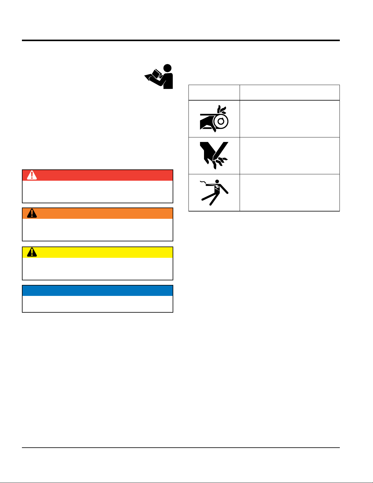
SAFETY SYMBOLS
DANGER
Indicates a hazardous situation which, if not avoided,
WILL result in DEATH or SERIOUS INJURY.
WARNING
Indicates a hazardous situation which, if not avoided,
COULD result in DEATH or SERIOUS INJURY.
equipment will be referenced with hazard symbols which
may appear throughout this manual in conjunction with
safety messages.
Symbol Safety Hazard
Rotating parts hazards
Cutting and crushing hazards
Electric shock hazards
CAUTION
Indicates a hazardous situation which, if not avoided,
COULD result in MINOR or MODERATE INJURY.
NOTICE
Addresses practices not related to personal injury.
PAGE 6 — TP24 TILE SAW • OPERATION AND PARTS MANUAL — REV. #2 (04/12/12)
Page 7
GENERAL SAFETY
NOTICE
This equipment should only be operated by trained and
Whenever necessary, replace nameplate, operation and
accident due to equipment modifi cations. Unauthorized
recommended by Multiquip for this equipment. Damage
keep
Also, know the phone numbers
fi re department.
SAFETY INFORMATION
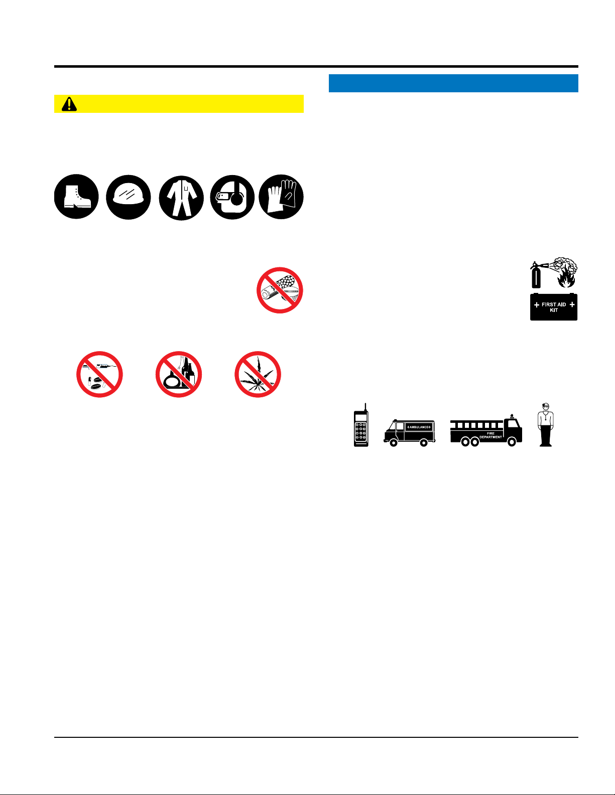
CAUTION
NEVER operate this equipment without proper protective
clothing, shatterproof glasses, respiratory protection,
hearing protection, steel-toed boots and other protective
devices required by the job or city and state regulations.
Avoid wearing jewelry or loose fi tting clothes that may
snag on the controls or moving parts as this can cause
serious injury.
NEVER operate this equipment when not
feeling well due to fatigue, illness or when
under medication.
NEVER operate this equipment under the
infl uence of drugs or alcohol.
ALWAYS clear the work area of any debris, tools, etc.
that would constitute a hazard while the equipment is
in operation.
qualifi ed personnel 18 years of age and older.
safety decals when they become diffi cult read.
Manufacturer does not assume responsibility for any
equipment modifi cation will void all warranties.
NEVER use accessories or attachments that are not
to the equipment and/or injury to user may result.
ALWAYS know the location of the nearest
fi re extinguisher.
ALWAYS know the location of the nearest
fi rst aid kit.
ALWAYS know the location of the nearest phone or
a phone on the job site.
of the nearest ambulance, doctor and
This information will be invaluable in the case of an
emergency.
No one other than the operator is to be in the working
area when the equipment is in operation.
ALWAYS check the equipment for loosened threads or
bolts before starting.
DO NOT use the equipment for any purpose other than
its intended purposes or applications.
TP24 TILE SAW • OPERATION AND PARTS MANUAL — REV. #2 (04/12/12) — PAGE 7
Page 8
SAFETY INFORMATION
SAW SAFETY
RPM) to the recommended blade surface feet per minute
ensure the proper tool has been matched to the material
blade is being
CAUTION
DANGER
NEVER operate the equipment in an explosive atmosphere
or near combustible materials. An explosion or fi re could
result causing severe bodily harm or even death.
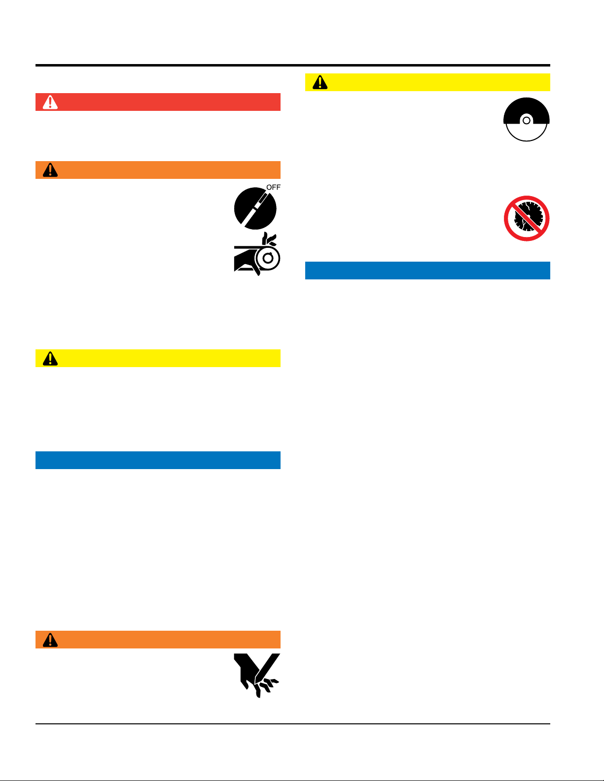
WARNING
Accidental starting can cause severe injury
or death. ALWAYS place the ON/OFF
switch in the OFF position.
Keep hands away from moving parts at all
times.
NEVER di sco nne ct an y emerg enc y
or safety devices. These devices are
intended for operator safety. Disconnection of these
devices can cause severe injury, bodily harm or even
death. Disconnection of any of these devices will void
all warranties.
CAUTION
ALWAYS ensure saw is securely placed on appropriate
blocks or jackstands when maintenance requires
elevation of the saw.
If the machine malfunctions, stop the saw immediately
and secure it. Fix the problem as soon as possible.
NOTICE
ALWAYS keep the machine in proper running condition.
Fix damage to machine and replace any broken parts
immediately.
Make sure there is no buildup of grease, oil or debris
on the machine.
ALWAYS store equipment properly when it is not being
used. Equipment should be stored in a clean, dry location
out of the reach of children and unauthorized personnel.
BLADE SAFETY
WARNING
NEVER operate the saw without blade
guards and covers in place. Exposure of
the diamond blade must not exceed 180
degrees.
Verify the motor start switch is set to the OFF position
before installing a blade.
A LWAYS inspect blade before ea ch
use. The blade should exhibit no cracks,
dings, or fl aws in the steel centered core
and/or rim. Center (arbor) hole must be
undamaged and true.
NOTICE
Use proper blades and follow blade manufacturer’s
recommendations. Match the blade RPM (blade shaft
(SFPM).
E n sure t h e blad e -moun t ing bo l t is ti g htene d
adequately
ALWAYS examine blade flanges for damage and
excessive wear.
Ensure the blade is marked with an operating speed
greater than the spindle speed of the saw.
Only cut the material that is specifi ed for the diamond
blade. Read the specifi cation of the diamond blade to
being cut.
If wet cutting, ensure a WET CUTTING
used and that the water supply system to the blade is
properly functioning and being used.
D O NOT drop the diamond blade on ground or
surface.
Ensure that the blade is mounted for proper operating
direction.
Adhere to the blade manufacturer’s recommendations
on handling, storage and safe usage of blades.
Rotating blade can cut and crush. ALWAYS
keep hands and feet clear while operating
the saw.
PAGE 8 — TP24 TILE SAW • OPERATION AND PARTS MANUAL — REV. #2 (04/12/12)
Page 9
SAFETY INFORMATION
ELECTRIC MOTOR SAFETY
LIFTING SAFETY
allow any person or animal to stand underneath
Some saws are very heavy and awkward to move around.
Ensure that the diamond blade does not come into contact
transport the saw to or from the job site with the
pour waste, oil or fuel directly onto the ground,
NOTICE
Operate electric motor only at the specifi ed voltage
indicated on the nameplate.
DO NOT spray water onto electric motor.
ALWAYS disconnect AC power plug from power source
before moving saw, changing blade, or performing
maintenance.
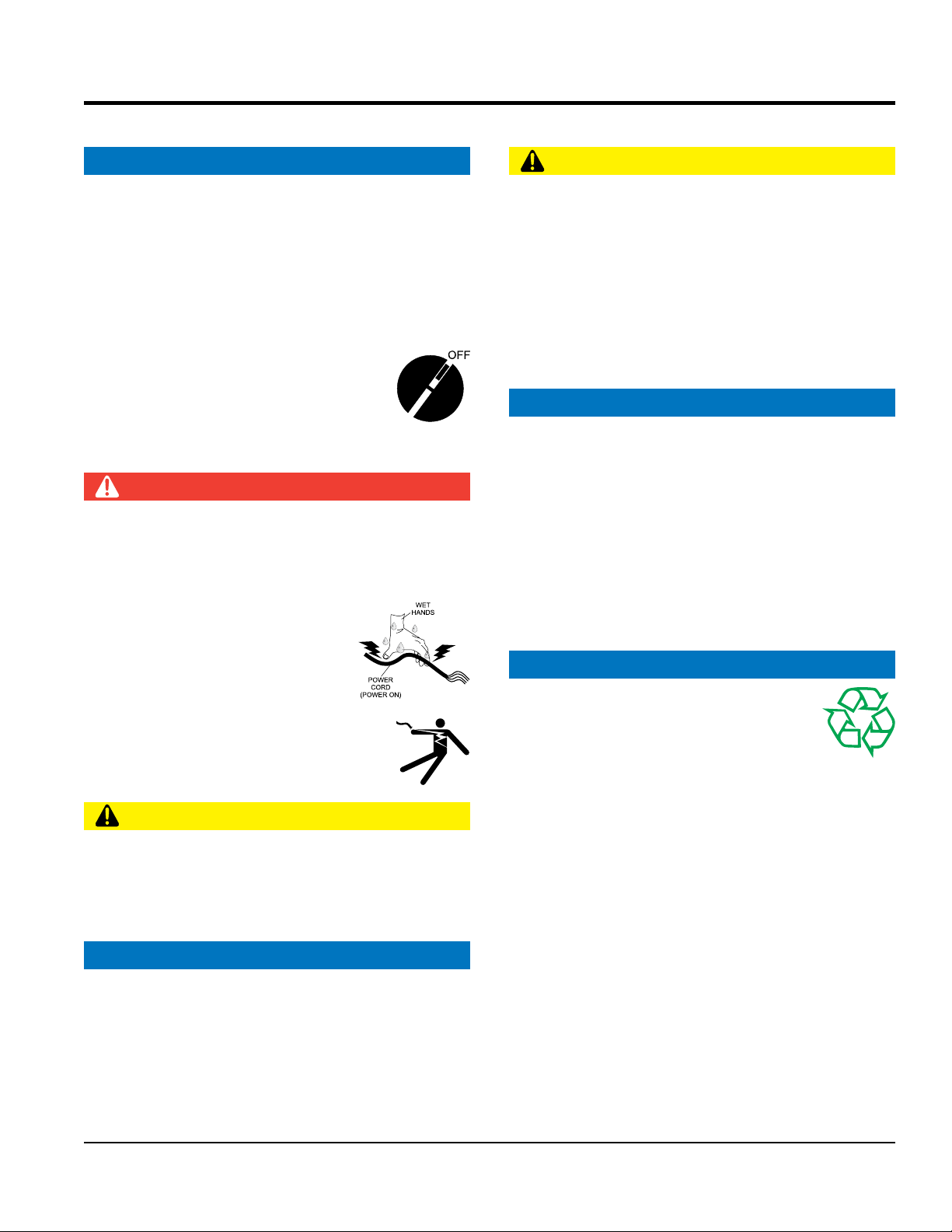
ALWAYS make sure the ON/OFF switch
on the electric motor is in the OFF position
when not in use and before inserting the
saw’s power plug into an AC receptacle.
Power Cord/Cable Safety
DANGER
NEVER let power cords or cables lay in water.
NEVER use damaged or worn cables or cords when
connecting equipment to generator. Inspect for cuts in
the insulation.
CAUTION
NEVER
the equipment while lifting.
Use proper heavy lifting procedures.
DO NOT lift machine to unnecessary heights.
NEVER lift the equipment while the motor is running.
TRANSPORTING SAFETY
NOTICE
ALWAYS shutdown motor before transporting.
ALWAYS tie down equipment during transpor t by
securing the equipment with rope.
with the ground or surface during transportation.
NEVER
blade mounted.
NEVER grab or touch a live power
cord or cable with wet hands. The
possibility exists of electrical shock,
electrocution or death.
Make sure power cables are securely
connected. Incorrect connections may
cause electrical shock and damage to the
saw.
CAUTION
Ensure that cables and cords will not be tripped over or
trapped underneath the saw.
Never use the cable to pull out the plug from the power
source.
NOTICE
ALWAYS make certain that proper power or extension
cord has been selected for the job.
Protect the cable from heat, oil, and sharp edges.
ENVIRONMENTAL SAFETY
NOTICE
Dispose of hazardous waste properly.
Examples of potentially hazardous waste
are used motor oil, fuel and fuel fi lters.
DO NOT use food or plastic containers to dispose of
hazardous waste.
DO NOT
down a drain or into any water source.
TP24 TILE SAW • OPERATION AND PARTS MANUAL — REV. #2 (04/12/12) — PAGE 9
Page 10

Table 1. Saw Specifications
SPECIFICATIONS
Model
Blade Capacity
Blade RPM
Arbor Size
Blade Guard
Blade Shaft Bearings
Cutting Head
Conveyor Cart
Drive System
Max. Depth of Cut
Straight Cut
Diagonal Cut
Water Tray
Water Pump
Weight
Table 2. Electric Motor Specifications
TP24
10 in. (254 mm)
3200
5/8 in. (15.875 mm)
Cast Aluminum
Water-Cooled
Cast Aluminum, Adjustable
Aluminum with roller bearings, injected
molded rubber pad, transportation lock
V-belt
3-1/2 in. (90 mm)
24 in. (610 mm)
16 in. (406 mm) x 16 in. (406 mm) Size Tile
ABS
115V, 60 Hz — 100 GPH
65 lbs. (29 kg)
Horsepower
Volts
Amps
Motor RPM
Cycle
Phase
Class
2
115
15
3000 RPM
60
1
E
PAGE 10 — TP24 TILE SAW • OPERATION AND PARTS MANUAL — REV. #2 (04/12/12)
Page 11
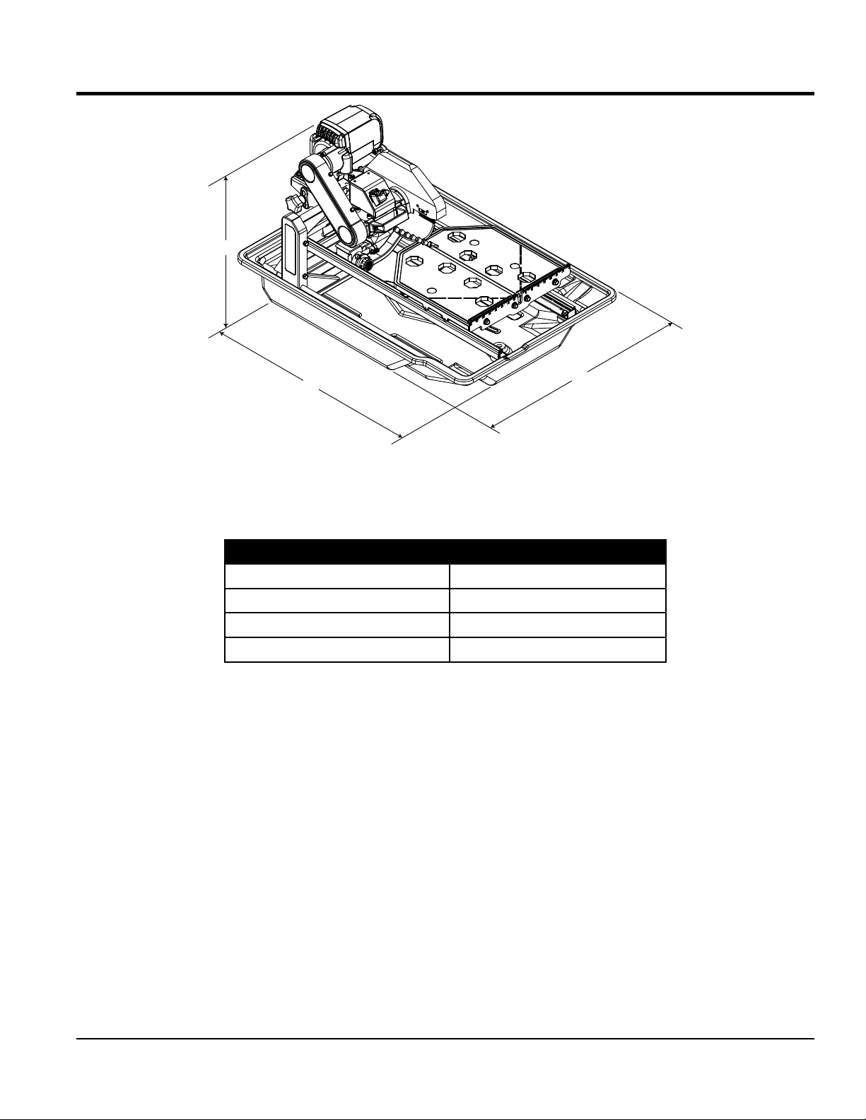
DIMENSIONS
C
A
Figure 1. Dimensions
B
Table 3. Dimension
Reference Letter Dimensions
A 36.5 in. (927 mm)
B 26 in. (660 mm)
C 20.4 in. (518 mm)
TP24 TILE SAW • OPERATION AND PARTS MANUAL — REV. #2 (04/12/12) — PAGE 11
Page 12

GENERAL INFORMATION
The TP2 4 i s a powerful, robust saw designed to
professionally handle large-sized cuts on ceramics, stone,
and masonry materials. A sturdy steel precision frame and
easily removable ABS water tray provides overall durability
and longevity.
This saw is equipped with a trusted high-torque 2 HP
electric motor that operates on standard 115 V power and is
designed with thermal overload and fan air cover protection.
An innovative water-cooled bearing assembly works in
conjunction with the water pump to keep key bearing
components running cooler.
The TP24 saw comes complete with premium blade and
high flow water pump.
DRY CUTTING APPLICATIONS
The TP24 tile saw is shipped from the factory for wet-cutting
saw applications, however it can be used for dry-cutting
saw applications. The most import thing to remember is to
disconnect the water pump. The water pump is cooled by
the flow of water, and failure to disconnect the pump (when
running dry) will cause pump failure.
NOTICE
NEVER have the water pump engaged when dry cutting
applications are involved.
BLADE APPLICATIONS
ACCESSORIES/REPLACEMENT PARTS
If desired, the TP24 tile saw can be equipped with a support
stand with wheels. This stand is ideal when the saw needs
to be placed on a secure reliable platform.
FEATURES
Rugged Portable Frame Assembly — Sturdy steel
frame design with handles for easy transport.
Electric Induction Motor — UL/CSA approved 115 V
60 Hz, 2 HP electric motor with thermal overload and
fan cover protection.
Water Tray — Sturdy ABS water tray that is easily
removable for cleaning.
Cutting Table — Rugged cast aluminum table with
heavy-duty injected molded rubber padding and
extension table. Industrial ball bearing rollers ensure
smooth, precise cart movement.
Water Pump — Powerful, maintenance-free, submersible
pump provides high volume water flow.
Water-Cooled Blade Shaft Bearing Assembly — High
flow water circulating system designed to keep crucial
bearing components running cooler.
Blade Guard — Hardy cast guard with blade brushes
designed to evenly distribute water to the blade, and to
easily position for blade changes.
This saw has been designed to incorporate the use
of diamond blades as the cutting tool. The optimum
performance of this saw is best evidenced by using 10-inch
(254 mm) diamond blades that match the material being
cut. Ask your dealer, or call Multiquip about your specific
cutting application.
PAGE 12 — TP24 TILE SAW • OPERATION AND PARTS MANUAL — REV. #2 (04/12/12)
Diamond Blade — 10-inch (254 mm) premium tile blade
included.
Page 13

NOTES
TP24 TILE SAW • OPERATION AND PARTS MANUAL — REV. #2 (04/12/12) — PAGE 13
Page 14
SAW COMPONENTS
5
9
3
1
22
4
2
7
17
23
21
19
11
10
6
8
12
13
14
20
16
18
15
24
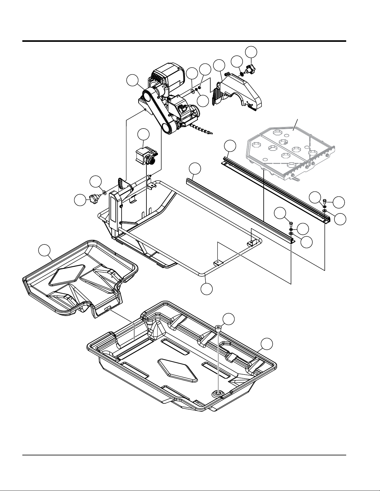
Figure 2. Saw Components
PAGE 14 — TP24 TILE SAW • OPERATION AND PARTS MANUAL — REV. #2 (04/12/12)
Page 15

SAW COMPONENTS
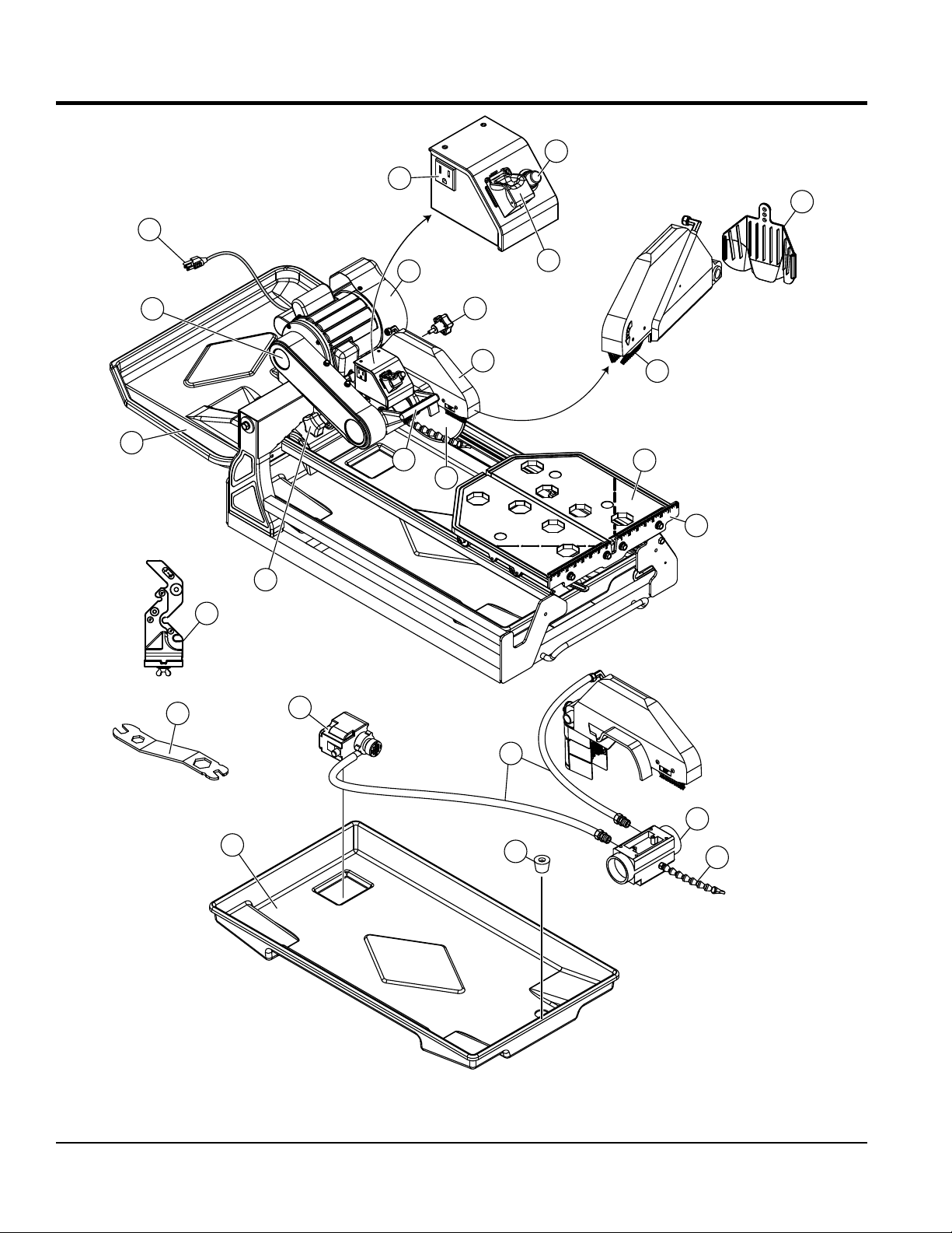
Figure 2 shows the location of the basic components of
the TP24 saw. Listed below is a brief explanation of each
component.
1. AC Power Cord — Plug this cord into a 125 VAC receptacle
when starting of the electric motor is required.
2. V-belt Cover — Remove this cover to access the drive
V-belt. NEVER operate the saw with the V-belt cover
removed
3. Rubber Splash Guard — Keeps water from splashing
from the blade.
4. Electric Motor — This unit uses a 115V, 60 Hz, 2 HP
electric motor.
5. Overcurrent Breaker Button — When a thermal
overload condition exists, press this button to reset the
breaker. Allow time for the electric motor to cool down
before reseting the breaker.
6. Cutting Blade — This unit uses a 10-inch (254 mm)
premium diamond blade. Always use recommended
Multiquip cutting blades. When mounting of the cutting
blade is required, remove the spindle bolt and outside
blade flange. Align cutting blade with inside flange arbor
and reassemble spindle and outside blade flange.
7. Cutting Head Handle — Grab hold of this handle to
control the movement of the cutting head.
8. Power ON/OFF Switch — To turn on the saw place
in the ON position. Place in the OFF position to shut
down the saw.
9. Water Pump Power Receptacle — Plug the water
pump power cord into this AC receptacle.
10. Blade Guard — Protects the user from the cutting
blade. NEVER operate the saw with the blade guard
removed.
11. Blade Guard Adjustment Knob — Turn knob
clockwise to loosen and remove blade guard. Turn
counterclockwise to tighten.
12. Blade Guard Brushes — Prevents foreign matter and
debris from accumulating on the saw blade. Replace
brushes immediately when they become worn or
damaged.
13. Cutting Table — Place material to be cut on this rubber
padded table. For ease of cutting, this table has been
placed on rails so that it can easily slide back and forth.
14. Ruler Backstop — When cutting, place material
against backstop. Use measurement rail (ruler) to
determine where material is to be cut.
15. Stopper — Place stopper in water tray when filling
with water.
16. Bearing Housing — Houses permanently lubricated ball
bearings to allow motor shaft to rotate smoothly.
17. Cutting Head Adjustment Knob — Turn knob
clockwise to loosen and position cutting head to desired
height. Turn counterclockwise to tighten.
18. Water Tray — When wet cutting is required, fill with
clean fresh water. Make sure submersible pump is
totally immersed in water.
19. Electric Water Pump — The electric water pump for
this saw requires 115 VAC. Plug power cord of electric
water pump into AC receptacle located on conduit
box. NEVER run pump dry. Pump must be immersed
in water.
20. Water Lines — Replace the clear vinyl tubing water
lines when they become brittle, worn or clogged. Water
kits are available through your Multiquip dealer.
21. Maintenance Wrench — Use this multi-purpose wrench
when performing maintenance or repairs on the saw.
22. Rear Drip Tray — Rear drip tray increases the surface
area for collecting water and slurry to prevent spillage.
23. MasterGuide Template Base — Mounts to ruler
backstop to ensures precision while making cuts.
24. Water LInk Hose — Recycles water from the bearing
housing back into the water tray.
TP24 TILE SAW • OPERATION AND PARTS MANUAL — REV. #2 (04/12/12) — PAGE 15
Page 16
ELECTRIC MOTOR COMPONENTS/SET-UP
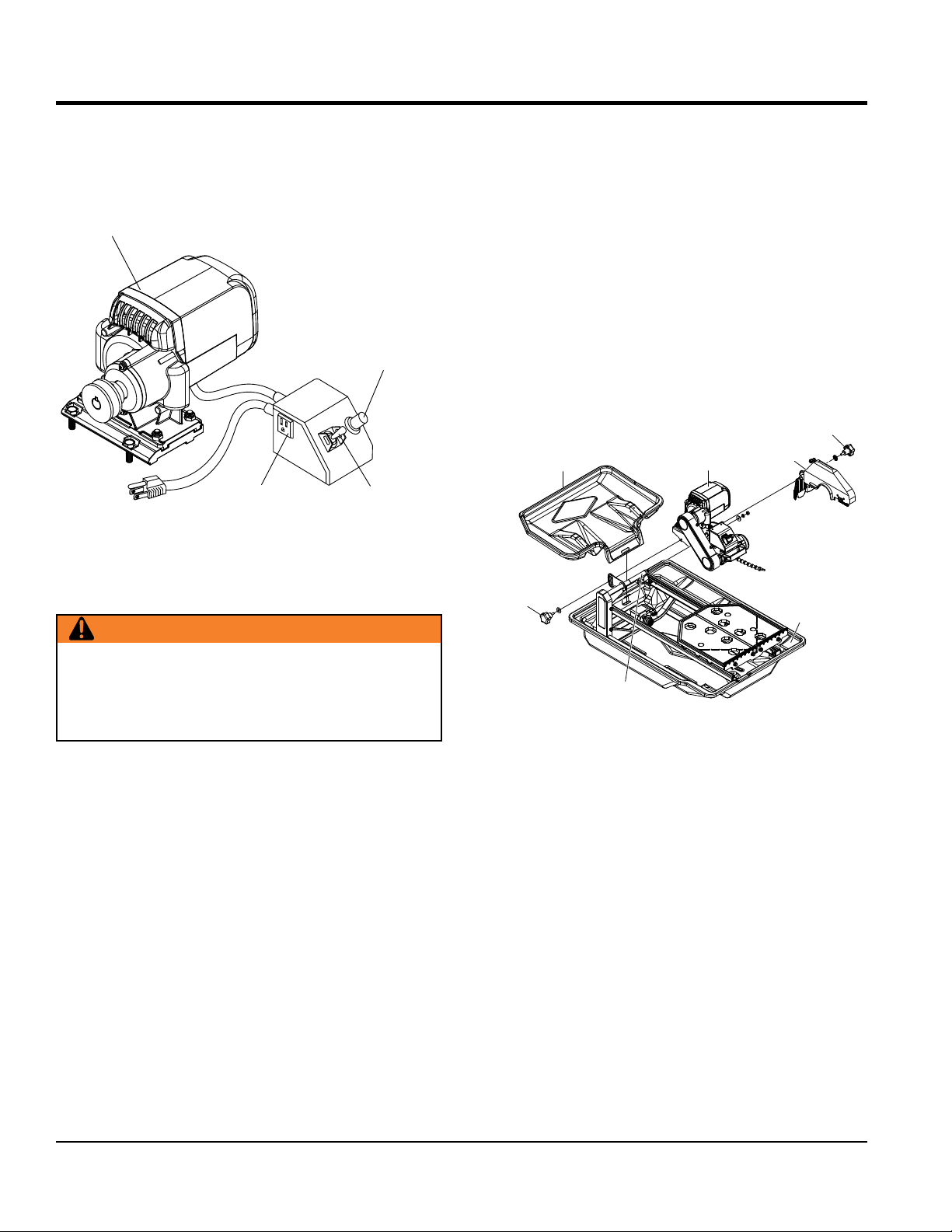
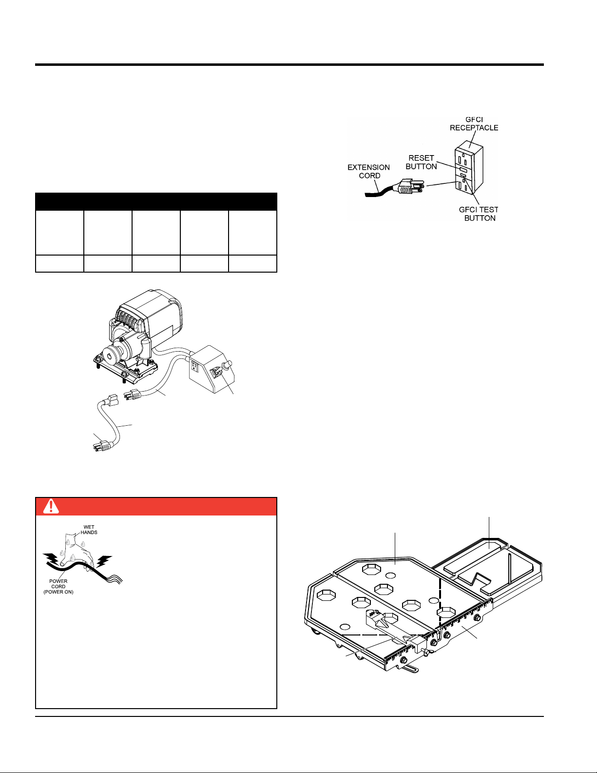
ELECTRIC MOTOR COMPONENTS
Figure 3 shows the location of the components of the
electric motor.
115 VAC, 60 Hz
SINGLE -PHASE
ELECTRIC MOTOR
OVERCURRENT
BREAKER BUTTON
ELECTRIC WATER
PUMP AC
RECEPTACLE
Figure 3. Electric Motor Components
ELECTRIC
MOTOR
ON/OFF SWITCH
SAW SET-UP
WARNING
3. Slide water pump onto U-shaped bracket located at
the bottom of the frame. See Figure 6.
4. Slide cutting head onto the post. Secure cutting head
to the shaft using provided flat washer, lock washer and
nut. Attach cutting depth control knob and washer to
the cutting head through the slot located underneath
the belt guard. See Figure 4.
5. Mount blade guard onto shaft protruding from the side
of the cutting head. Secure the blade guard in place
using the provided serrated washer and blade guard
knob.
6. Attach rear drip tray to the water tray.
BLADE
GUARD
WATER
TRAY
KNOB
CUTTING
DEPTH
CONTROL
KNOB
REAR
DRIP
TRAY
CUTTING
HEAD
BLADE
GUARD
Whenever cleaning, adjusting or lubricating any part
of the saw, make certain to place the power ON/OFF
switch in the OFF position and disconnect the plug from
the power source.
1. Open the shipping container carefully, lift the saw by
its carrying handles and place it on a suitable table or
platform. Make sure the table or platform can support
the weight of the saw.
2. Make sure that the following items are found in the
container:
Saw
Water Tray
Drain Plug
Universal Wrench
Water Pump
Rear Drip Tray
Owner’s Manual
Rip Guide
Saw Blade
SHAFT
Figure 4. Saw Assembly
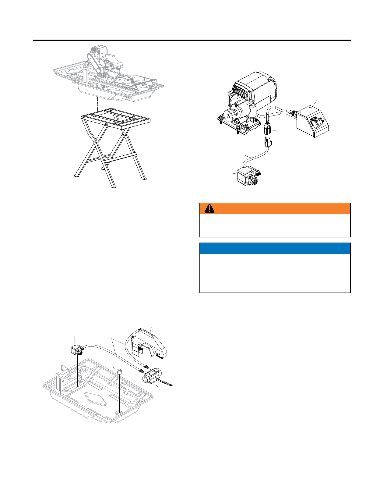
7. If using the optional support stand, assemble as
described in the Support Stand Assembly section.
Make sure that the saw is secured on the support
stand as instructed.
SUPPORT STAND ASSEMBLY (OPTIONAL)
Refer to Figure 5 for location of components.
1. Remove the folding stand from its box.
2. While holding the stand upright, spread both sets of
legs apart and swing the workbench over and on top
of the legs.
3. Seat the saw securely onto the stand.
PAGE 16 — TP24 TILE SAW • OPERATION AND PARTS MANUAL — REV. #2 (04/12/12)
Page 17
SET-UP
BEARING
HOUSING
8. Insert the water pump power plug into the outlet cable
receptacle from the electric motor conduit box as shown
in Figure 7.
ELECTRIC MOTOR
CONDUIT BOX
CONDUIT
BOX
CABLE
RECEPTACLE
WATER
PUMP
POWER
PLUG
Figure 5. Support Stand Assembly
CONNECTING THE WATER PUMP
Refer to Figure 6.
4. Attach the water hose coming from the blade guard
and bearing housing to the water pump.
5. Install drain plug in water tray.
6. Fill the water tray with clean fresh water. The water
pump intake must always be fully covered by water.
Also, keep the pump intake free of sludge, debris and
other materials that may accumulate in the tray.
7. Make certain that the water hose will not come in contact
with the blade or interfere with any moving parts.
BLADE
WATER
PUMP
WATER
HOSES
DRAIN
PLUG
GUARD
Figure 7. Water Pump Power Connection
WARNING
Disconnect the pump before attempting to handle the
pump. NEVER operate pump without water in the tray.
NOTICE
The above procedure is for wet cutting applications only.
NEVER dry cut with the pump connected to an AC power
source. Running the pump dry will damage the pump.
ALWAYS disconnect the pump’s power cord when dry cutting.
Figure 6. Connecting the Water Pump
TP24 TILE SAW • OPERATION AND PARTS MANUAL — REV. #2 (04/12/12) — PAGE 17
Page 18

SET-UP
MAX.RPM
SPECIFICATIONS
1
2
3
4
5
6
7
BLADES
WARNING
Failure to thoroughly inspect the blade for
operational safety could result in damage to
the blades or the saw and may cause serious
injury to the user or others in the operating
area. Inspect the blade flanges and shaft for
damage before installing the blade.
Blade Components
Diamond blades are recommended for your saw. Ask your
Multiquip dealer about your specific cutting application.
Figure 8 highlights the components of a diamond blade.
3. Directional Arrow — Check to ensure that the blade is
oriented properly on the spindle for sawing. Reference the
directional arrow on the blade and place it so the direction
of rotation “downcuts” with the turn of the shaft.
4. Diamond Segment or Rim — Ensure that there are
no cracks, dings, or missing portions of the diamond
segment/rim. DO NOT use a blade that is missing
a segment or a portion of the rim. Damaged and/or
missing segments/rims may cause damage to your saw
and injury to the user or others in the operating area.
5. Specifications — Ensure that the blade specifications,
size, and diameter properly match up to the sawing
operation. Wet blades must have water to act as a coolant.
Utilizing a diamond blade not matched properly to the task
may result in poor performance and/or blade damage.
6. Arbor Hole — It is essential that the arbor hole
diameter properly matches the shaft arbor, and that it
is free from distortions. Correct blade flanges (collars)
must be used. The inside face of the flanges must be
clean and free of debris. An out of round arbor condition
will cause damage to the blade and the saw.
7. MAX RPM — This RPM reference is the maximum safe
operating speed for the blade selected. NEVER exceed
the max RPM on the diamond blade. Exceeding the MAX
RPM is dangerous, and may cause poor performance
and may damage the blade. All blades used must be
designed for the maximum spindle RPM.
Cutting Depth
The recommended cutting depth is 1/4" (6 mm) below the
cutting table surface. To adjust the cutting depth, loosen the
cutting head adjustment knob so that the blade is 1/4" below
the top of the cutting table's surface. See Table 4 to determine
Figure 8. Diamond Blade
1. Stress Relief Holes (Gullets) — Check the steel core
for cracks that may have propagated from the slots
and/or gullets. Cracks indicate extreme fatigue failure
and if sawing continues, catastrophic failure will occur.
2. Edge of the Steel Core — Check the diameter edge for
cutting depth by blade diameter.
WARNING
Setting the blade too low may damage the cutting table
and if set too high, the blade may grab the material
being cut, causing damage and possibly injury.
discoloration (blue oxidation) indicating an overheating
condition caused by insufficient cooling water/air.
Overheating of blades may lead to loss of core tension
and/or increase the possibility for blade failure. Check
to make sure the steel core’s width is uniform about
the rim of the blade, and not succumbing to an “under
cutting” condition brought about by highly abrasive
Table 4. Blade Diameter vs. Cutting Depth
Blade Diameter Cutting Depth
7 in. (178 mm) 1-3/4 in. (44.5 mm)
10 in. (254 mm) 3-1/2" (90 mm)
material or improper under cutting core protection.
PAGE 18 — TP24 TILE SAW • OPERATION AND PARTS MANUAL — REV. #2 (04/12/12)
Page 19
SET-UP
BLADE
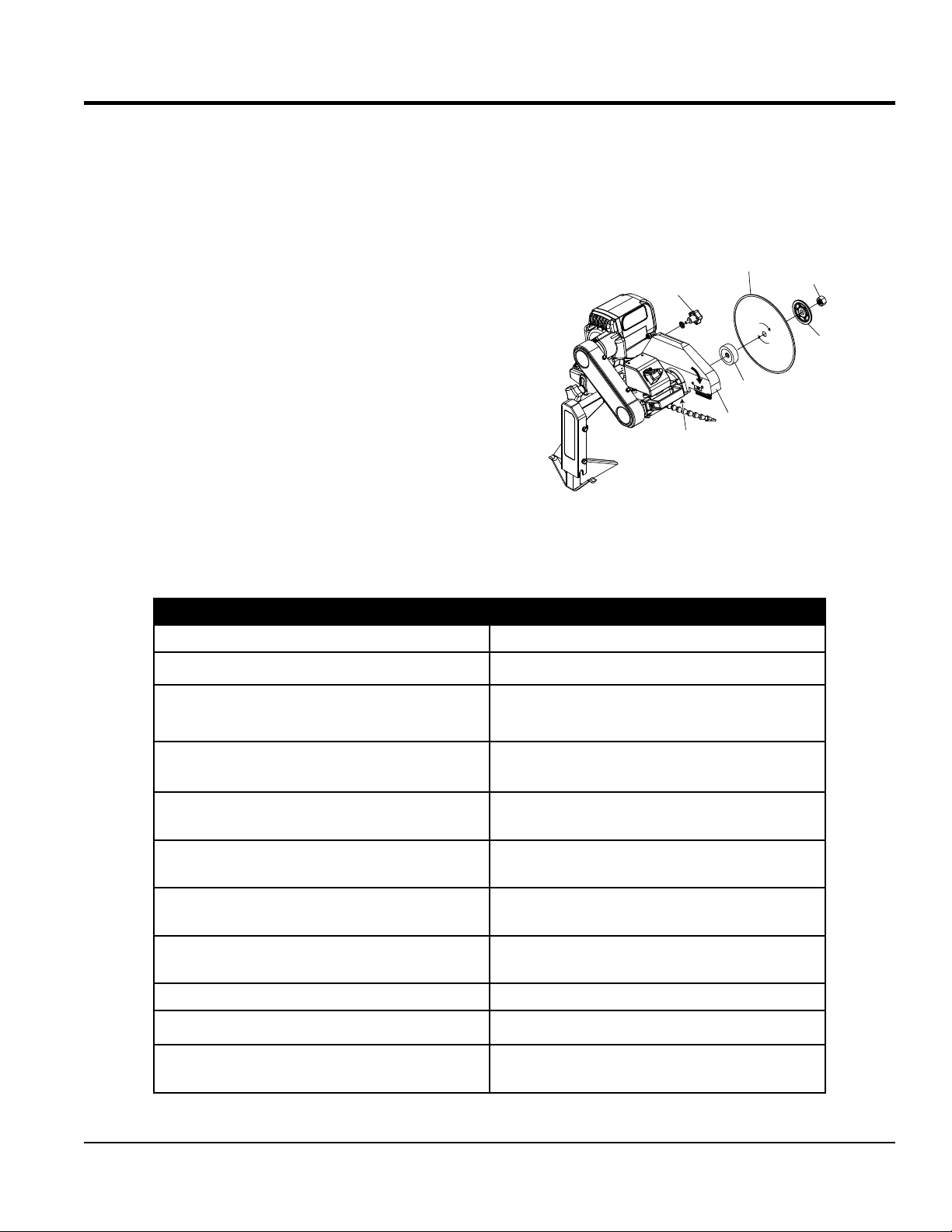
Blade Installation
Refer to Figure 9 and the following instructions for installing
the blade.
1. Loosen blade guard adjustment knob located at the
rear of the blade guard. Carefully raise the cutting
head to its highest position and secure it into place by
tightening the blade guard adjustment knob.
2. Remove the blade shaft nut and outer flange. If a blade
has been mounted, hold the blade with one hand and
use the other hand to loosen the nut with the universal
wrench. Remove existing blade.
3. Mount new blade, but make certain the arrow on the
blade coincides with the rotation direction of the shaft.
Ensure the capacity of the blade guard matches the
diameter of your cutting blade.
4. Attach outer flange and blade shaft nut. Hold the blade
with one hand and use the other hand to tighten the
nut with the universal wrench. Make certain the flanges
are pressed flush against the blade and that the nut is
firmly tighthened, but DO NOT over tighten.
5. Loosen blade guard adjustment knob, lower the blade
guard, and retighten the knob.
6. Slightly loosen the cutting head adjustment knob, lower
the cutting head so that the blade is 1/4" (6 mm) below
the surface of the cutting table. Tighten the adjustment
knob firmly to hold the cutting head in place.
GUARD
ADJUSTMENT
KNOB
BLADE
SHAFT
BLADE
FLANGE
BLADE
GUARD
INNER
Figure 9. Blade Installation
BLADE
SHAFT
NUT
OUTER
FLANGE
See Table 5 for proper blade use guidelines.
Table 5. Proper Blade Use
Dos Don’ts
Inspect blades daily for cracks or uneven wear. Do not operate the saw without safety guards in place.
Always use appropriate blades for material being cut.
Inspect arbor shaft for uneven wear before mounting
blade.
Always use blades with the correct arbor shaft size.
Ensure that blade is mounted in the correct
direction.
Use proper safety equipment when operating the saw.
Always have a continuous flow of water on both
sides of blade.
Secure the blade to the arbor with a wrench. Do not attempt to cut a radius or curve.
Inspect segment blades for segment cracking or loss. Do not cut too deep or too fast into the material.
Do not use damaged blades.
Do not operate the saw with blades larger than 10
in. (254 mm)
Do not cut dry with blades marked “Use Wet”.
Do not exceed manufacturer’s recommended
maximum RPM.
Do not force blade into material. Let blade cut at its
own speed.
Do not make long cuts with dry blades. Allow them
to air cool.
Do not use the edge or side of blade to cut or grind.
Do not cut any material not recommended by blade
manufacturer.
TP24 TILE SAW • OPERATION AND PARTS MANUAL — REV. #2 (04/12/12) — PAGE 19
Page 20
SET-UP/SAWING GUIDES
SIDE EXTENSION
CONNECTING THE POWER
1. Place the power ON/OFF switch (Figure 10) in the OFF
position (down).
2. Connect an extension cord of adequate current carrying
capacity to the power plug on the electric motor.
3. MAKE CERTAIN that the correct size extension cord
is used. Undersized wires will burn out motors. Use
Table 6 to determine the correct extension cord size.
Table 6. Extension Cord Sizes
(22.9 m)
ELECTRIC
MOTOR
75 ft
Long
50 ft
(15. 2 m)
Long
Motor
Voltage
VAC
25 ft
(7.6 m)
Long
2 HP 115 No. 12 No. 10 No. 8
ELECTRIC
MOTOR
CONNECT TO
115/230 VAC
POWER SOURCE
EXTENSION
CORD
POWER
PLUG
ON/OFF SWITCH
4. Plug the free end of the extension cord into an AC power
receptacle. Whenever possible use a GFCI receptacle
(Figure 11) to reduce the risk of electrical shock.
Figure 11. GFCI Receptacle
SAWING GUIDES
Using the Cutting Table
The ruler guide has inches marked along the top to allow
convenient measurements and to promote precision cuts.
See Figure 12.
The table spans an area of 16" x 16" (406 x 406 mm).
With the optional side extension table equipped, the cast
aluminum cutting table spans an area of 25" x 16" (635
x 406 mm), which allows it to provide greater support
for handling larger materials.
Cutting table is covered by a rubber mat that provides a
firm, durable work surface.
Figure 10. Extension Cord Connection
DANGER
NE VE R grab or touch a live
power cord with wet hands, the
possibility exists of electrical shock,
electrocution, and even death!
NEVER use a damaged or worn
extension cable when connecting
to a power source. Defective cables may cause damage
to the saw’s electric motor or electrical shock.
ALWAYS use a grounded (3-wire) extension cord
and MAKE CERTAIN that the motor is connected to
a properly grounded electric circuit. If possible use a
ground fault circuit interrupter to protect the operator
from possible electric shock.
PAGE 20 — TP24 TILE SAW • OPERATION AND PARTS MANUAL — REV. #2 (04/12/12)
A rip guide should be used with the cutting table to ensure
precision while making cuts.
TABLE (OPTION)
CUTTING TABLE
RULER GUIDE
RIP GUIDE
Figure 12. Cutting Table
Page 21
Using the Rip Guide
1. Set the rip guide at the desired location on the ruler
guide and tighten the threaded knob. Make sure that
the rip guide is firmly tightened to avoid slippage. The
rip guide can be used for 45° and 90° cuts.
2. After the rip guide is positioned, for the desired cut,
place material flat against the rip guide and ruler guide.
3. Now you are ready to make your cut.
Performing Diagonal Cuts
1. Remove threaded knob from the end of the rip guide
with the horizontal groove and insert it into the other
end with the diagonal groove.
2. Set the rip guide onto the ruler guide, such that the top
edge of the rip guide is aligned with the diagonal groove to
the left of the vertical channel in the cutting table. Tighten
threaded knob once in place.
SAWING GUIDES
3. Place one corner of the material being cut in the vertical
slot of the ruler guide and rest the adjoining edge flat
against the rip guide.
4. Now you are ready to make your cut.
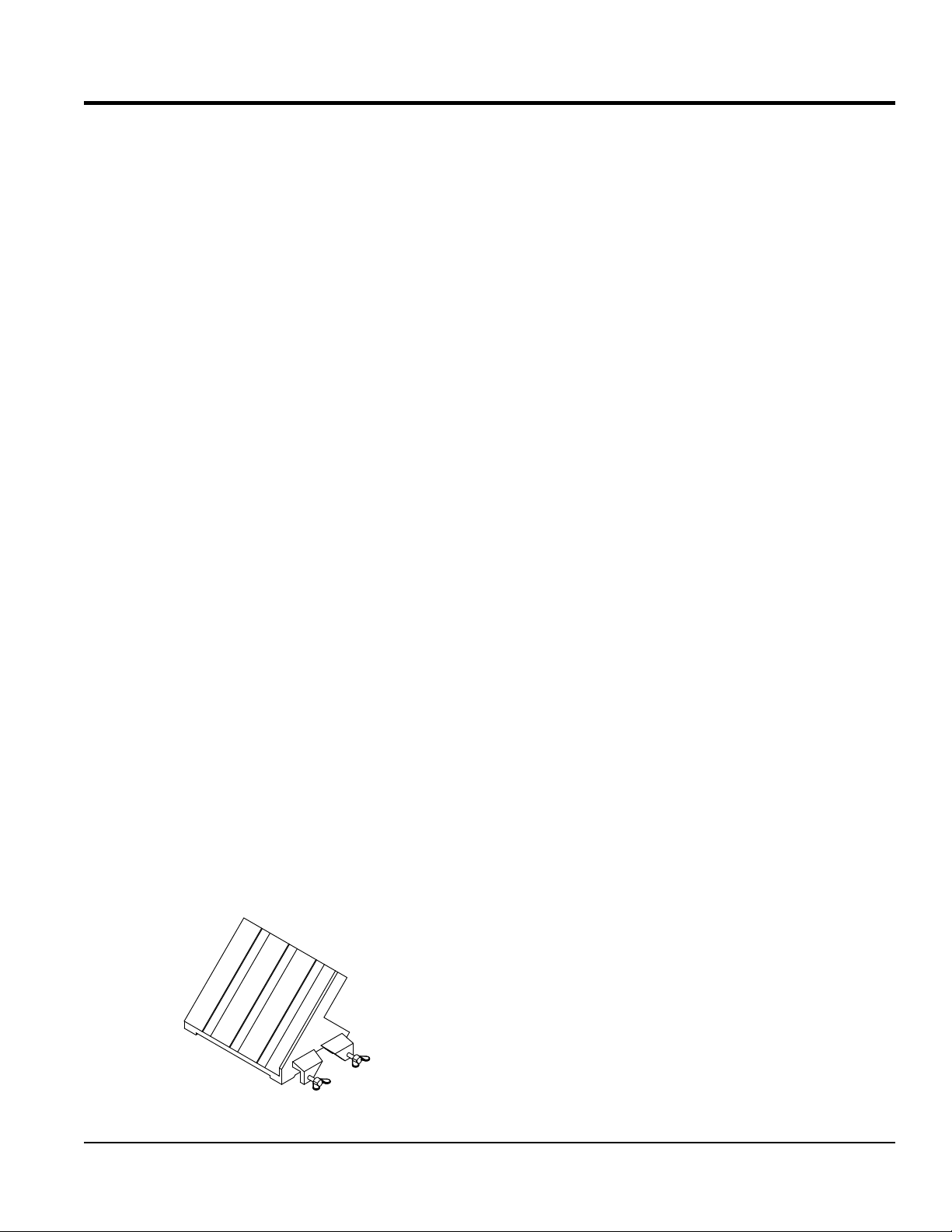
Performing Miter Cuts
To make miter cuts, an optional miter block must be purchased.
See Figure 13.
1. Place the lip of the miter block on the ruler guide with
the threaded knob facing you.
2. Position the miter block such that a tile laying flat
against the block may rest its left-most edge within
the vertical channel of the cutting table. Tighten the
threaded knob to secure the miter block in place.
3. Place material onto miter block and you are ready to cut.
Figure 13. Optional Miter Block
TP24 TILE SAW • OPERATION AND PARTS MANUAL — REV. #2 (04/12/12) — PAGE 21
Page 22

OPERATION
START-UP PROCEDURE
NOTICE
Read and fully understand this manual before
starting or attempting to operate the saw.
Before starting the saw’s electric motor
make sure that the Safety, General Information, and
Set-Up sections have been completed and understood.
DO NOT proceed until the above mentioned sections
have been completed.
NOTICE
ALWAYS use the water feed system unless special dry
cut blades are being used. If dry cutting is required,
disconnect water pump.
WARNING
NEVER place hands or feet inside the belt
guard or blade guard while the motor is
running. ALWAYS shut the motor down
before performing any kind of maintenance
WARNING
NEVER lift the blade guard while the blade
is rotating. The possibility exists of severe
bodily harm if fingers or hands come in
contact with the rotating saw blade. Wait
for the blade to stop rotating before lifting
the blade guard.
1. Place the material to be cut (Figure 14) on the cutting
table against the backstop.
CUTTING
TABLE
MATERIAL
BACKSTOP
Figure 14. Material Placement
WARNING
ALWAYS wear approved eye and hearing
protection before operating the saw.
WARNING
NEVER place hands and fingers near
the cutting blade. The possibility exists of
severe bodily harm if hands and fingers
come in contact with rotating saw blade.
WARNING
ALWAYS ensure that the cutting blade has
been mounted correctly.
DANGER
NEVER touch a live power cord with wet
hands. The possibility exists of electrical
shock, electrocution which could cause
severe bodily harm, even death.
DANGER
ALWAYS be alert to the fact that there is a rotating
blade on the saw and be extremely aware of your body
position — especially your hands in relationship to the
rotating blade. The possibility exists of severe bodily
harm or even death if your body comes in contact with
the rotating saw blade.
2. Turn the power ON/OFF switch (Figure 15) to the ON
position with the blade away from the material to be
cut, the cutting blade should begin to rotate. Before
cutting remember to follow all safety rules referenced
in this manual.
Figure 15. Power ON/OFF Switch (ON)
PAGE 22 — TP24 TILE SAW • OPERATION AND PARTS MANUAL — REV. #2 (04/12/12)
Page 23

3. Push the cutting table with the material, slowly and
evenly until the cut is complete. Move the cutting table
back and remove the cut pieces.
4. Avoid overloading the motor when cutting. However,
the electric motor is protected with a manual-reset
thermal overload switch that will turn the saw off if the
motor is overheated. In the event that the switch is
tripped, turn the “ON/OFF” switch to the “OFF” position
and allow the motor to cool before attempting to restart.
SHUT DOWN PROCEDURE
1. Place the power ON/OFF switch (Figure 16) in the OFF
position (down).
OPERATION
Figure 16. Power ON/OFF Switch (OFF)
2. Wait for the cutting blade to stop rotating.
3. Disconnect the saw's AC power cord from the power
source. NEVER leave the saw connected to a power
source when unattended. This will prevent accidental
starting.
4. Using a soft cloth, clean any excess debris or residue
that may have accumulated on the saw.
5. Store saw in a clean dry location where it will be out
of the reach of children.
TP24 TILE SAW • OPERATION AND PARTS MANUAL — REV. #2 (04/12/12) — PAGE 23
Page 24

MAINTENANCE
A good preventive maintenance program of regular
inspection and care will increase life and improve the
performance of the saw and cutting blades.
WARNING
Whenever cleaning, adjusting, or lubricating any part of
the saw, MAKE CERTAIN to do the following:
• Place power ON/OFF switch to the OFF position.
• Disconnect power cord from AC source.
• NEVER attempt to check the V-belt with the engine
running. Severe bodily injury can occur.
BASIC MAINTENANCE
1. Tighten loose nuts or screws and replace any cracked
or broken parts.
2. Clean the machine frequently. DO NOT use aggressive
cleaners (i.e. containing solvents). DO NOT use high
high-pressure water jets, aggressive detergents or
solutions and liquids with a temperature exceeding
86°. Use a fluff-free cloth only. Use a cloth which may
be lightly moistened only for removing dust and dirt.
Hard packed dirt can be removed with a soft brush.
5. After each day's use, run clean water through the
water pump and water hoses. This extends pump and
blade life.
6. After cleaning, remove all covers and adhesive tape. All
screws or nuts which may have been loosened must
be retightened.
7. Check the spindle bolt for tightness periodically.
8. Keep the drive belt tight. It is very important to replace
worn belts as soon as possible. To adjust belt tension,
loosen the four (4) motor mounting bolts and remove
the belt guard. Tighten the adjusting nut on the back
of the motor plate to increase the tension. Proper belt
tension is 4-5 lbs. of force with approximately 3/16" of
belt deflection measured at a point midway between the
pulleys. Tighten the motor mounting bolts and reattach
the belt guard.
9. MAKE CERTAIN that the cutting head is aligned
properly. Misalignment can adversely affect blade life.
10. The blade flanges must have a diameter of 4".
Undersized flanges will reduce blade life and cause
breakage. Therefore, they should be replaced at
once.
DO NOT let any water/cleaning liquid/vapor penetrate
into the electric motor, connectors/plugs, switches, etc.
Cover all apertures, holes in the housing, connectors
or plugs, etc, or seal them with adhesive tape.
Use a soft, low-pressure water jet and a brush to rinse
dirt and incrustations away. Be particularly careful when
near hazardous parts of the machine (e.g. switch,
motor). Clean the motor and switches only by wiping
with a moist cloth.
3. Remove the belt guard and clean the pulleys. The belts
and pulleys will wear rapidly if excessive dust builds up.
4. Clean the sludge that accumulates on the bottom of
the water tray at least once a day and refill with clean
water. It may be necessary to clean the tray out twice
a day in heavy cutting. The sludge is abrasive and will
shorten the life of the water pump and blades.
11. Cutting blades must fit the arbor snugly. This is very
important with diamond blades as pounding will occur
and serious blade damage can result. If the arbor
shoulder of the inner blade flange is grooved from blade
slippage, the flange must be replaced.
12. Inspect the cutting table periodically. Replace worn
parts.
13. DO NOT “rinse” the bearings of the drive elements to
prevent them from running dry. The ball bearings of the
machine are permanently lubricated.
14. Replace the spindle bearings as soon as they begin to
make any strange noises. Worn bearings can destroy
blades very quickly.
15. Grease pivot bearings periodically.
PAGE 24 — TP24 TILE SAW • OPERATION AND PARTS MANUAL — REV. #2 (04/12/12)
Page 25

MAINTENANCE
MAINTENANCE INTERVALS
Use the following guidelines to perform maintenance on
your saw.
After every use of the machine
Remove dirty water from container.
Remove dirt and mud from the bottom of the container.
Rinse the immersion pump with fresh water to prevent
water pump clogging from residual dirt.
After wet cleaning and before using the machine
again
Connect the machine to an electric power outlet
equipped with a “GFCI” safety power breaker. If the safety
power breaker cuts off the electrical power supply, do
not try to operate the machine but have it checked by
an authorized dealer first.
Before not using the machine for a prolonged
period of time
Check that the immersion pump works properly. Turn
on the cooling water tap and switch the machine on. If
the pump does not give any water or only a little, switch
the machine off at once. Clean the pump, or replace if
necessary.
Ambient temperature below 32°F / 0°C (operation
in winter)
To prevent the water in the pump and cooling system
from freezing, remove the water after using the machine
or when there will be a long break. Make sure that the
cooling system is entirely drained so that there is no
water left inside the pump and water hose.
CLEANING THE WATER TRAY
Refer to Figure 17.
1. Remove the rear drip tray.
2. Lift the saw up from inside the water tray.
3. Remove the drain plug and drain any water left inside
the water tray.
Clean and lubricate all movable parts. DO NOT grease
guide rails.
After not using the machine for a prolonged period
of time
Check that the stand is safely fixed.
Check that all screw joints and nuts are fixed.
Check that the cutting table is seated properly on the
guide rails and that it easily moves along the entire
length of the rails.
With the saw blade removed, switch on the motor for an
instant and switch it off again. If the motor does not run,
have the machine inspected by a qualified electrician.
4. Flush water into tray while holding it upright to remove
any sludge buildup.
5. Replace the saw back into the water tray.
6. Attach the rear drip tray.
Figure 17. Water Tray Removal
TP24 TILE SAW • OPERATION AND PARTS MANUAL — REV. #2 (04/12/12) — PAGE 25
Page 26

WATER PUMP MAINTENANCE
When the machine has not been used for a long period of
time, hard packed dirt may build up inside the pump and
block the pump wheel.
NOTICE
If the machine is activated with the immersion pump
blocked, the electric motor will be damaged within a
few minutes!
Please follow the steps below to clean the pump before
operating the saw.
1. Remove the immersion pump from the water container.
2. Clean the immersion pump.
MAINTENANCE
Figure 18. Belt Replacement
3. Loosen the fixing screws of the pump lid.
4. Take the lid off the pump (be careful not to damage or
lose the gasket underneath)
5. Clean the pump lid.
6. Remove all dirt and incrustations from the pump wheel.
7. Check whether the pump wheel can be easily turned.
8. Reassemble the immersion pump and check that it
works properly.
BELT REPLACEMENT
To replace the belt (Figure 18) perform the following.
1. Turn off and unplug the saw.
2. Loosen and remove the 4 bolts located above and
below the belt guard. Remove the belt guard.
3. Loosen the 4 bolts located at the base of the motor.
4. Use a hex wrench to access the socket hex bolt located
at the rear of the cutting head. Turn wrench to move the
motor forward, thus providing some slack in the belt.
CUTTING HEAD REMOVAL
To remove the cutting head, see Saw Set-Up
BEARING HOUSING REMOVAL
To remove the bearing housing (Figure 19), perform the
following:
1. Remove the 4 screws on the belt guard.
2. Remove the belt guard.
3. Loosen (do not remove) the adjustment screw behind
the mounting plate and the 4 screws on the motor base
to remove the belt.
4. Remove the blade lock nut and remove the blade (if
there is one present.)
5. Remove the 4 screws on the mounting plate closest to
the cutting head handle to remove the bearing housing
(including the attached pulley and inner flange.)
5. Take off the old belt and replace with new belt.
6. To reassemble, follow steps 1-4 in reverse order. Make
sure belt is at the proper tension before tightening the
four bolts at the base of the motor.
PAGE 26 — TP24 TILE SAW • OPERATION AND PARTS MANUAL — REV. #2 (04/12/12)
Page 27
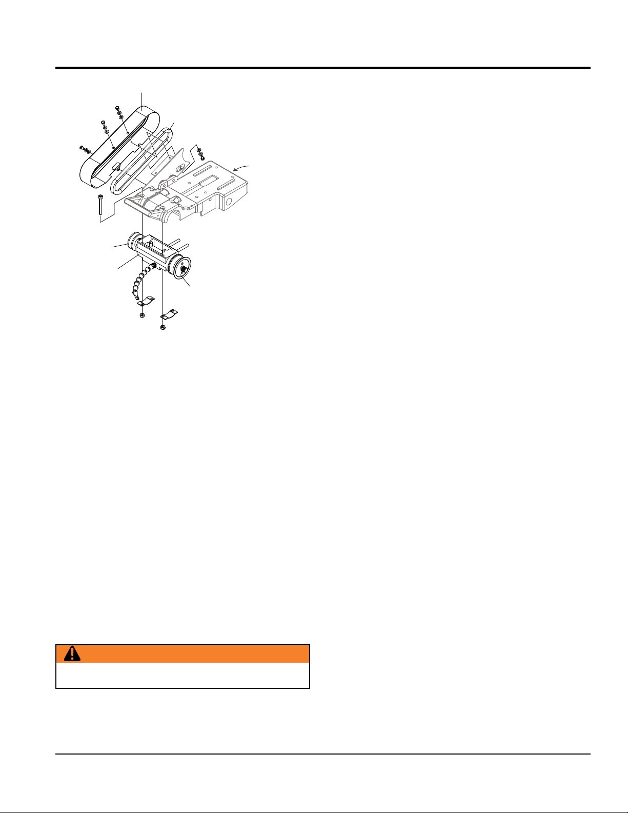
BELT
GUARD
BELT
ADJUSTMENT
SCREW
PULLEY
BEARING
HOUSING
INNER
FLANGE
Figure 19. Bearing Housing Removal
MAINTENANCE
BEARING HOUSING INSTALLATION
To install a new bearing housing, perform the following:
1. Make sure that the old housing has been properly
removed.
2. Unpack the new bearing housing and place the flat
portion face-down on a towel situated on a flat surface.
3. Secure the cutting head in a in a completely horizontal
position.
4. Slide the new bearing housing with the flat portion
facing upwards onto the 4 screws located below the
mounting plate. Take care not to damage the inner
flange. Lock the bearing housing into place by using
the brackets and nuts.
5. Pull the motor towards you, place the belt on the
pulleys, and tighten the motor position adjustment
screw. Be sure to leave some slack on the belt.
6. Align the belt by adjusting the motor pulley after
loosening the hex screw.
WARNING
Do not adjust the bearing housing pulley.
7. After aligning the belt, tighten the hex screw.
8. Replace the belt guard and lock into place using 4 screws.
TP24 TILE SAW • OPERATION AND PARTS MANUAL — REV. #2 (04/12/12) — PAGE 27
Page 28
LEAVE A 1/32 IN.
MAINTENANCE
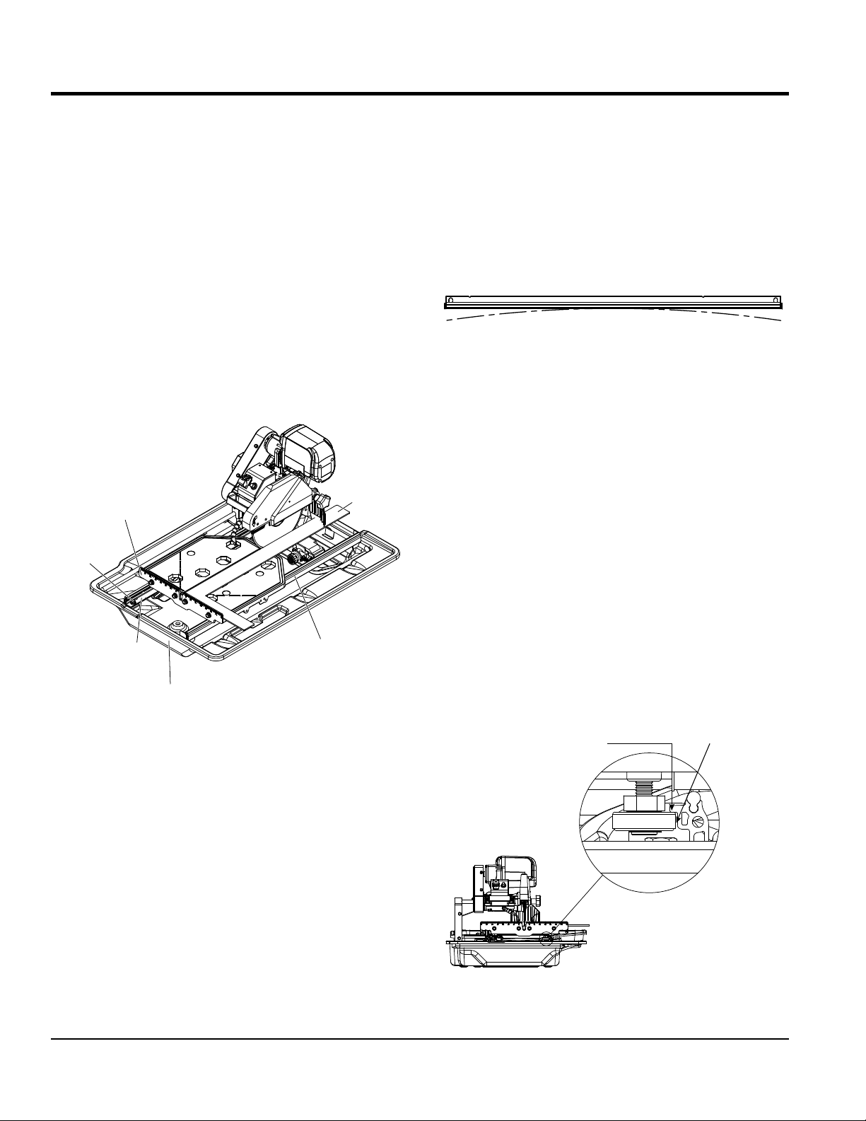
REALIGNMENT
Method 1
This procedure deals with the most common source of
misalignment that occurs when the guide rails are not
parallel with the blade.
1. Set the cutting depth such that the blade passes
through the table, not over.
2. Place a straight edge (i.e. carpenter’s square) on the
cutting table as shown in Figure 20.
3. Loosen the left and right guide rails by loosening the
fasteners found at the ends of the rail. The left rail
should be slightly loose, so there is not too much play
during adjustments, but the right rail should move freely.
STRAIGHT
RIGHT
GUIDE
RAIL
EDGE
RULER
GUIDE
FASTENER
LEFT
GUIDE
RAIL
FRONT
Figure 20. Realigning Guide Rails
4. Make sure the short portion of the straight edge is placed
flush against the ruler guide. Adjust the left guide rail
so that the front and rear edges of the blade touch the
straight edge, although a tolerance of 0.1mm (.004 in.)
between the front and rear edges is allowed. Perform this
adjustment along the entire length of the straight edge.
required. However, if scenario A or B (described below)
occurs, other adjustments may be required instead.
a. If the straight edge only touches the blade when
the table is positioned midway along the rail or at
the ends of the rail, then the rail may be deformed
(i.e. bowed). See Figure 21. Perform test cuts to
determine if the rail should be replaced. Typically,
a bowing displacement of up to 0.2mm (.008 in.)
will not affect cutting accuracy.
Figure 21. Rail Deformation
b. If the straight edge touches both edges of the blade
intially, but shifts apart as the table travels along
the rail, proceed to Method 2.
6. Tighten the fasteners at both ends of the left rail.
7. Adjust the right guide rail so that the horizontal rollers
underneath the table engage the rail as shown in
Figure 22. In most cases the rollers will not have to
be vertically adjusted. Spacing between rails must
be equidistant at all points to ensure that they are
parallel. Once adjustments are made, lightly tighten
the fasteners on the right rail and move the table back
and forth. If the table binds against the rail at any
point, adjust spacing accordingly until the table moves
smoothly.
8. Tighten the fasteners at both ends of the right rail.
If alignment has been achieved, do not proceed to Method 2.
LEAVE HAIRLINE GAP
BETWEEN RAIL AND ROLLER
(1MM) GAP
5. Position the table as close to the user as possible. Place the
straight edge flush against the ruler guide and blade. Without
holding onto the straight edge, gently move the table towards
the rear of the saw and then back. Observe any gaps that may
appear between the straight edge and blade or between the
straight edge and ruler guide. A gap exceeding the allowed
tolerance means that the table is not moving parallel to the
blade; hence, further adjustments as outlined below will be
PAGE 28 — TP24 TILE SAW • OPERATION AND PARTS MANUAL — REV. #2 (04/12/12)
Figure 22. Adjust Right Guide Rail
Page 29

Method 2
HORIZONTAL
This procedure corrects another source of misalignment
that occurs when the table’s orientation is not parallel with
the guide rails.
1. Use the universal wrench to loosen (but not remove)
the fasteners from either end of both guide rails. Move
each rail away from the other, so that the horizontal
rollers are clear of the right guide rail. See Figure 23.
Figure 23. Roller Clearance
2. Remove rubber cap A on the left side of the table.
Loosen the exposed lock nut using a 13mm socket
wrench. Use a flat screwdriver to turn the shaft of the
roller clockwise to lower it by approximately 3/8 in. (9.5
mm). See Figure 24. Evenly lift up the table to
disengage the guide rollers from the left guide rail.
Once the guide rollers are clear, shift the table to the
right to clear the left horizontal roller of the rail. Remove
the table from the guide rails. See Figure 25.
RUBBER
CAP A
HORIZONTAL
FASTENERS
FLAT
SCREW
DRIVER
ROLLER
LOOSEN
CLEARANCE
RIGHT
GUIDE
RAIL
MAINTENANCE
GUIDE
ROLLER
LEFT
GUIDE
3. If the table shifts to the right as it travels away from
the user, a shim needs to be added to the guide roller
furthest from the ruler guide. On the other hand, if
the table shifts to the left, a shim needs to be added
to the guide roller closest to the ruler guide. Remove
the appropriate guide roller to insert a shim between
the roller and table, then reattach. See Figure 26.
Depending on the severity of the shift, more than one
shim may be required.
4. After adding shim(s), mount the table onto the guide
rails by reversing the instructions in step 2. Move the
rails toward each other to engage the horizontal rollers
to the right guide rail as shown in Figure 22. Realign
the table to the blade using Method 1. Check to see if
any shifting persists. A shift tolerance of 0.2mm (.008
in.) is allowed. A shift in excess of that will require
further adjustment—repeat step 3.
1
2
HORIZONTAL
ROLLER
RAIL
Figure 25. Remove Table
FLAT
ROLLER
13MM
SOCKET
WRENCH
GUIDE
ROLLER
SHIM
RUBBER
CAP C
RUBBER
CAP B
Figure 26. Add Shims
Figure 24. Lowering Roller
5. Once alignment is successful, replace saw back into
water tray.
TP24 TILE SAW • OPERATION AND PARTS MANUAL — REV. #2 (04/12/12) — PAGE 29
ROLLER
Page 30

MAINTENANCE
Leveling Adjustment
This procedure levels the table so that it is perpendicular
to the blade and flush against the rails.
1. Remove rubber caps B and C on the right side of the
table. Loosen the exposed lock nuts using a socket
wrench. Next, use a flat screwdriver to turn the shaft
of the rollers clockwise. See Figure 24. This will lower
the horizontal rollers to allow room for adjusting the
flat rollers.
2. Loosen the socket bolts on the flat roller plate so that
the roller can swing freely about one bolt. see Figure
27. Do this for both flat roller plates.
3. Hold the table against the guide rails. The flat rollers
should reposition themselves to maintain contact with
the guide rails. If the table is not perpendicular to the
blade, lift the right side of the table instead to obtain the
proper angle. A square tool will be required to confirm
the angle. Tighten the socket bolts. Check the table for
play. Repeat step 2 if some play is still present.
TRANSPORTING THE SAW
1. Ensure that the water tray is empty and dry.
2. Unplug the power cord and store it in the water tray.
3. Secure the cutting table to the front of the saw using
the table retention device.
4. Tighten the cutting depth control knob.
5. Optionally, the rear drip tray may be removed and set
in the water tray for better handling.
4. Restore the horizontal rollers to their original positions
as shown in Figure 22 by reversing the instructions in
step 1. Be sure to tighten the lock nuts and replace
the rubber caps.
FLAT ROLLERS
ROTATE IN
THIS MANNER
Figure 27. Flat Roller Rotation
PAGE 30 — TP24 TILE SAW • OPERATION AND PARTS MANUAL — REV. #2 (04/12/12)
Page 31

WIRING DIAGRAM (ELECTRIC MOTOR)
Black
White
Green
Power Outlet for Water Pump
Power Cable
Green
Green
White
Switch
Black Black Black
Wiring Box
Figure 28. Electric Motor Wiring Diagram
Motor
Overcurrent
Black
White
White
Breaker
TP24 TILE SAW • OPERATION AND PARTS MANUAL — REV. #2 (04/12/12) — PAGE 31
Page 32

TROUBLESHOOTING (BLADE)
Table 7. Blade Troubleshooting
Symptom Possible Problem Solution
Irregular run of the saw blade Poor tension in the blade material Return saw blade to manufacturer
Have the saw blade aligned/flattened
Chean the receiving flange
Replace saw blade.
Replace saw blade.
Use appropriate type of saw bladeSaw blade type is unsuitable for the machine
Arbor of the saw blade must be fitted with an
appropriate adapter ring
Check the receiving flange and have it
replaced if necessary
Ensure optimum flow of cooling water
The material feed is too high; proceed more
slowly
Ensure that the direction of the feed is
absolutely parallel to the saw blade
Adjust roller table
The material feed is too high; proceed more
slowly
Saw blade wobbles when running
Diamond segment becomes loose
Excessive wear
Cracks in or near diamond segment
Saw blade is blunt
Appearance of cut is not optimal
Center hole in saw blade has become wider
due to wear
Saw blade shows blooming colors
Grinding marks on the saw blade
Saw blade is damaged or bent
Flange of the saw blade is damaged Replace the saw blade flange
Shaft of the motor is bent Replace the electric motor
Overheating of the saw blade; cooling water
not sufficient
Wrong type of saw blade Use harder saw blade
Shaft of motor causes wobbling Have motor or bearings of motor replaced
Overheating Ensure optimum flow of cooling water
Saw blade too hard Use softer blade
Fixed flange is worn out Have fixed flange replaced
Motor shaft bearing Replace the bearing of the motor shaft
Saw blade type is unsuitable for the material
being cut
performance
Saw blade too hard
Diamond segments are blunt Replace saw blade.
Poor tension in the blade material Return saw blade to manufacturer
Too much load placed on saw blade Use a suitable saw blade
Diamond segments are blunt Replace saw blade.
Saw blade has slipped on the motor shaft
when running
Saw blade overheating due to lack of cooling
water
Lateral friction when cutting
Material is not being fed parallel to saw blade
Poor tension in blade material Have the saw blade tensioned
Too much load on the saw blade
PAGE 32 — TP24 TILE SAW • OPERATION AND PARTS MANUAL — REV. #2 (04/12/12)
Page 33

Symptom Possible Problem Solution
Machine does not run when switched on
Motor stops (power cuts out)
Poor machine performance, little power
Insufficient flow of cooling water or no cooling
water at all
TROUBLESHOOTING (SAW)
Table 8. Saw Troubleshooting
Power cord not properly fixed/plugged in
Power cord defective
Main power switch defective
Loose electrical connection inside the electric
system
Motor defective
Too much pressure exerted while cutting Exert less pressure when cutting
Incorrect specification for saw blade
Saw has a defective electric system
Power cord/extension cable too long or cable
still wound up inside cable drum
Power network is insufficient
Drive motor no longer runs at rated speed
(RPM)
The water pump draws air Fill the water tray with water
Filter clogged Clean the filter of the water pump
Pump wheel of the immersion pump is
blocked by dirt
Check that the machine is properly
connected to the power supply
Have the power cord checked, replace if
necessary
Have the main power switch checked and
replaced if necessary by a qualifed electrician
Have the whole electric system of the
machine checked by a qualified electrician
Have the motor checked and replaced if
necessary by a qualified technician
Use a saw blade which corresponds to the
material being cut
Have the electric system of the saw checked
by a qualified technician
Use a power cord/extension cable of the
rated length, use a cable drum with cable
fully extended
Observe the electrical ratings of the machine
and connect it only to a power network which
complies with these ratings
Have the motor checked by a qualified
electrician and replace if necessary
Disassemble the immersion pump and clean it
TP24 TILE SAW • OPERATION AND PARTS MANUAL — REV. #2 (04/12/12) — PAGE 33
Page 34

EXPLANATION OF CODE IN REMARKS COLUMN
The following section explains the different symbols and
PART NO. Column
QTY. Column
— Item quantity can be indicated by a
A/R (As Required) is generally used for hoses or other
A blank entry generally indicates that the item is not sold
separately. Other entries will be clarifi ed in the “Remarks”
Some of the most common notes found in the “Remarks”
Column are listed below. Other additional notes needed
same unique symbol will be included when this item is
— Used to list an effective serial
— Indicates that the part
part is NOT used on a specifi c model or model number
available items. Examples include battery cables, shims,
— Indicates that an item cannot
be purchased as a separate item and is either part of an
assembly/kit that can be purchased, or is not available
remarks used in the Parts section of this manual. Use the
help numbers found on the back page of the manual if there
are any questions.
Numbers Used
number, a blank entry, or A/R.
NOTICE
The contents and part numbers listed in the parts
section are subject to change without notice. Multiquip
does not guarantee the availability of the parts listed.
SAMPLE PARTS LIST
NO. PART NO. PART NAME QTY. REMARKS
1 12345 BOLT .....................1 .....INCLUDES ITEMS W/%
2% WASHER, 1/4 IN. ..........NOT SOLD SEPARATELY
2% 12347 WASHER, 3/8 IN. ..1 .....MQ-45T ONLY
3 12348 HOSE ..................A/R ...MAKE LOCALLY
4 12349 BEARING ..............1 .....S/N 2345B AND ABOVE
NO. Column
Unique Symbols — All items with same unique
symbol
(@, #, +, %, or >) in the number column belong to the
same assembly or kit, which is indicated by a note in the
“Remarks” column.
Duplicate Item Numbers — Duplicate numbers indicate
multiple part numbers, which are in effect for the same
general item, such as different size saw blade guards in
use or a part that has been updated on newer versions
of the same machine.
NOTICE
When ordering a part that has more than one item
number listed, check the remarks column for help in
determining the proper part to order.
parts that are sold in bulk and cut to length.
Column.
REMARKS Column
to describe the item can also be shown.
Assembly/Kit — All items on the parts list with the
purchased.
Indicated by:
“INCLUDES ITEMS W/(unique symbol)”
Serial Number Break
number range where a particular part is used.
Indicated by:
“S/N XXXXX AND BELOW”
“S/N XXXX AND ABOVE”
“S/N XXXX TO S/N XXX”
Specifi c Model Number Use
is used only with the specifi c model number or model
number variant listed. It can also be used to show a
variant.
Indicated by:
Numbers Used — Part numbers can be indicated by a
number, a blank entry, or TBD.
TBD (To Be Determined) is generally used to show a
part that has not been assigned a formal part number
at the time of publication.
A blank entry generally indicates that the item is not sold
separately or is not sold by Multiquip. Other entries will
be clarifi ed in the “Remarks” Column.
“XXXXX ONLY”
“NOT USED ON XXXX”
“Make/Obtain Locally” — Indicates that the part can
be purchased at any hardware shop or made out of
and certain washers and nuts.
“Not Sold Separately”
for sale through Multiquip.
PAGE 34 — TP24 TILE SAW • OPERATION AND PARTS MANUAL — REV. #2 (04/12/12)
Page 35

TP24 TILE SAW WITH ELECTRIC MOTOR
1 to 3 units
Qty. P/N Description
1............TP100072 ............. V-BELT
1............TPS100003 ........... SWITCH, TOGGLE 15A
1............TP100152 ............. CARBON BRUSH
NOTICE
Part numbers on this Suggested Spare Parts list may
supersede/replace the part numbers shown in the
following parts lists.
SUGGESTED SPARE PARTS
TP24 TILE SAW • OPERATION AND PARTS MANUAL — REV. #2 (04/12/12) — PAGE 35
Page 36
MAIN SAW ASSY.
9
8
3
14
12
2
13
CUTTING
TABLE
15
28
28
8
9
21
5
1
6
4
26
21
27
26
27
PAGE 36 — TP24 TILE SAW • OPERATION AND PARTS MANUAL — REV. #2 (04/12/12)
Page 37

MAIN SAW ASSY.
NO. PART NO. PART NAME QTY. REMARKS
1 TP100125 FRAME ASSY 1
2 TP100127 CUTTING HEAD ASSY 1
3 TP100129 10" BLADE GUARD ASSY 1
4 TP100143 WATER TRAY 1
5 TP100144 WATER TRAY, BACK DRIP 1
6 TP100140 PLUG, WATER TRAY 1
8 TP100138 M10 SPRING WASHER 2
9 TP100139 KNOB, M8 X 1.25 X 20L 1
12 TP100141 WASHER, M8 1
13 TP100080 WASHER SPRING M10 1
14 TP100086 NUT, M8 X 1 1
15 TP100132 WATER PUMP, 230 GAL/HR 1
21 TP100109 BOLT, HEX M8 X 1.25 X 16L 4
26 TP100080 WASHER, SPRING M8 4
27 TP100141 WASHER, NARROW M8 4
TP24 TILE SAW • OPERATION AND PARTS MANUAL — REV. #2 (04/12/12) — PAGE 37
Page 38

SWITCH
BOX
ASSY.
CUTTING HEAD ASSY.
28
23
21
18
23
21
18
18
45
21
23
4
35
18
21
23
27
47
46
24
36
34
3
20
17
15
43
44
25
22
16
7
1
2
13
10
11
12
BEARING
HOUSING
ASSY.
6
14
6
14
PAGE 38 — TP24 TILE SAW • OPERATION AND PARTS MANUAL — REV. #2 (04/12/12)
Page 39

CUTTING HEAD ASSY.
NO. PART NO. PART NAME QTY. REMARKS
1 TP100064 MOUNTING PLATE 1
2 TP100068 SHAFT, BLADE GUARD 1
3 TP100069 BRACKET, BELT GUARD 1
4 TP100067 BELT GUARD 1
6 TP100077 BRACKET, LCBH 2
7 TP100074 BRACKET, MOTOR TENSION 1
10 BLADE, 10" GENERAL PURPOSE ...................1................CONTACT UNIT SALES
11 TP100136 FLANGE, UNIVERSAL, DIA 5/8" 1
12 TP100137 NUT, 5/8-11 UNC 1
13 TP100075 RUBBER STOP, CIRCULAR D6 1
14 TP100086 NUT, NYLON M8 X 1.25 4
15 TP100085 BOLT, HHSC M8 X 1.25 X 70L X 28 4
16 TP100142 WASHER, M8 1
17 TP0120 WASHER, M8 NARROW 2
18 TP100061 WASHER, NARROW M6 4
20 TP0121 WASHER, M8 LOCK 2
21 TP100081 WASHER, SPRING M5 4
22 TP100083 BOLT, HHSC, M8 X 1.25 X 55L X 28 1
23 TP100062 BOLT, HEX M6 X 1 X 10L 4
24 TP100087 BOLT, HEX, M8 X 1.25 X 12L 2
25 TP100082 NUT, M8 X 1 4
27 TP100072 V-BELT, 23" 1
28 TP100066 MOTOR ASSY 1
34 TP100092 PULLEY, MOTOR 1
35 TP100093 KEY, SQUARE 5 X 5 X 30L 1
36 TP100094 SET SCREW, FLAT POINT, M6 X 1 X 10L 1
43 TP100080 WASHER, SPRING M8 4
44 TP100079 WASHER, NARROW M8 4
45 TP100084 BOLT, HHS M6 X 1 X 20L 2
46 TP100061 WASHER, NARROW M6 2
47 TP100073 HANDLE, RECTANGLE 26.5H X 7W X 93L 1
TP24 TILE SAW • OPERATION AND PARTS MANUAL — REV. #2 (04/12/12) — PAGE 39
Page 40
ELECTRIC MOTOR ASSY.
7
5
10
12
6
14
2
8
9
16
3
9
8
1
4
13
11
15
PAGE 40 — TP24 TILE SAW • OPERATION AND PARTS MANUAL — REV. #2 (04/12/12)
Page 41

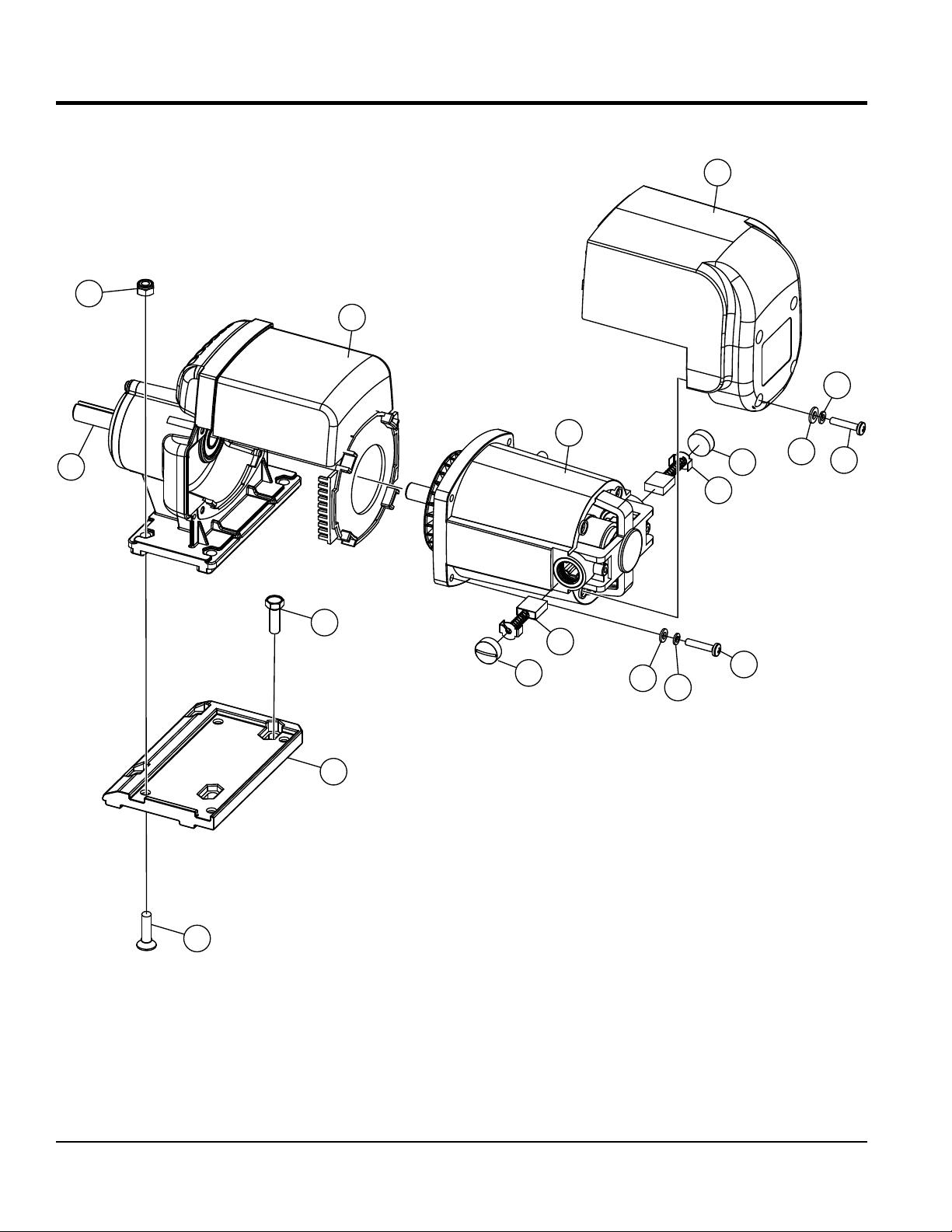
ELECTRIC MOTOR ASSY.
NO. PART NO. PART NAME QTY. REMARKS
1 TP100145 MOUNTING BLOCK 1
2 TP100146 MOTOR ASSY, M2 2HP 1
3 TP100147 BOLT, HEX M8 X 1.25 X 25L 4
4 TP100148 BOLT, COUNTERSUNK SOCKET, M8 X 1.25 X 30L 1
5 TP100082 NUT, NYLON M8 X 1.25 4
6 TP100149 ARMATURE AND WINDING ASSY 1
7 TP100150 MOTOR COVER 1
8 TP100151 CAP, CARBON BRUSH 2
9 TP100152 CARBON BRUSH, 17MM X 7 M (SET OF 2) 1
10 TP100153 WIND BAFFLE 1
11 TP100154 WASHER, SPRING M5 4
12 TP100155 WASHER, SPRING M4 4
13 TP100156 WASHER, NARROW M5 4
14 TP100157 WASHER, NARROW M4 4
15 TP100158 CROSS SCREW, M5 X .8 X 25L 4
16 TP100159 CROSS SCREW, M4 X .7 X CROSS SCRE
TP24 TILE SAW • OPERATION AND PARTS MANUAL — REV. #2 (04/12/12) — PAGE 41
Page 42

CUTTING TABLE ASSY.
8
19
12
11
8
1
8
11
2
2
4
18
SIDE EXTENSION
TABLE (OPTION)
18
12
1515
12
5
11
1515
11
17
6
13
10
17
14
PAGE 42 — TP24 TILE SAW • OPERATION AND PARTS MANUAL — REV. #2 (04/12/12)
11
9
3
9
3
3
12
16
16
Page 43

CUTTING TABLE ASSY.
NO. PART NO. PART NAME QTY. REMARKS
1 TP100095 CUTTING TABLE 1
2 TP100097 GUIDE ROLLER (SET OF 2) 1
3 TP100098 CONCENTRIC FLAT ROLLER 3
4 TP100099 RULER GUIDE 1
5 TP100100 SPRING LOCK ASM 1
6 TP100101 SPRING 1
8 TP100103 RUBBER CAP 3
9 TP100105 FLAT ROLLER ASM (SET OF 2) 1
10 TP0322 HEX BOLT M6X1.0X10L 1
11 TP100082 NUT M8X1 9
12 TP0121 WASHER LOCK M8 12
13 TP100081 WASHER LOCK M6 1
14 TP25095 HEX BOLT M6X1.0X30L 1
15 TP100107 HEX BOLT M8X1.25X25L 2
16 TP100108 HEX BOLT M8X1.25X20L 4
17 TP0384 WASHER NARROW M6 2
18 TP0120 WASHER NARROW M8 6
19 TP100109 HEX BOLT M8X1.25X20L 4
TP24 TILE SAW • OPERATION AND PARTS MANUAL — REV. #2 (04/12/12) — PAGE 43
Page 44
BLADE GUARD ASSY.
10
10
8
1
2
12
11
9
6
3
5
13
10
3
4
7
PAGE 44 — TP24 TILE SAW • OPERATION AND PARTS MANUAL — REV. #2 (04/12/12)
Page 45

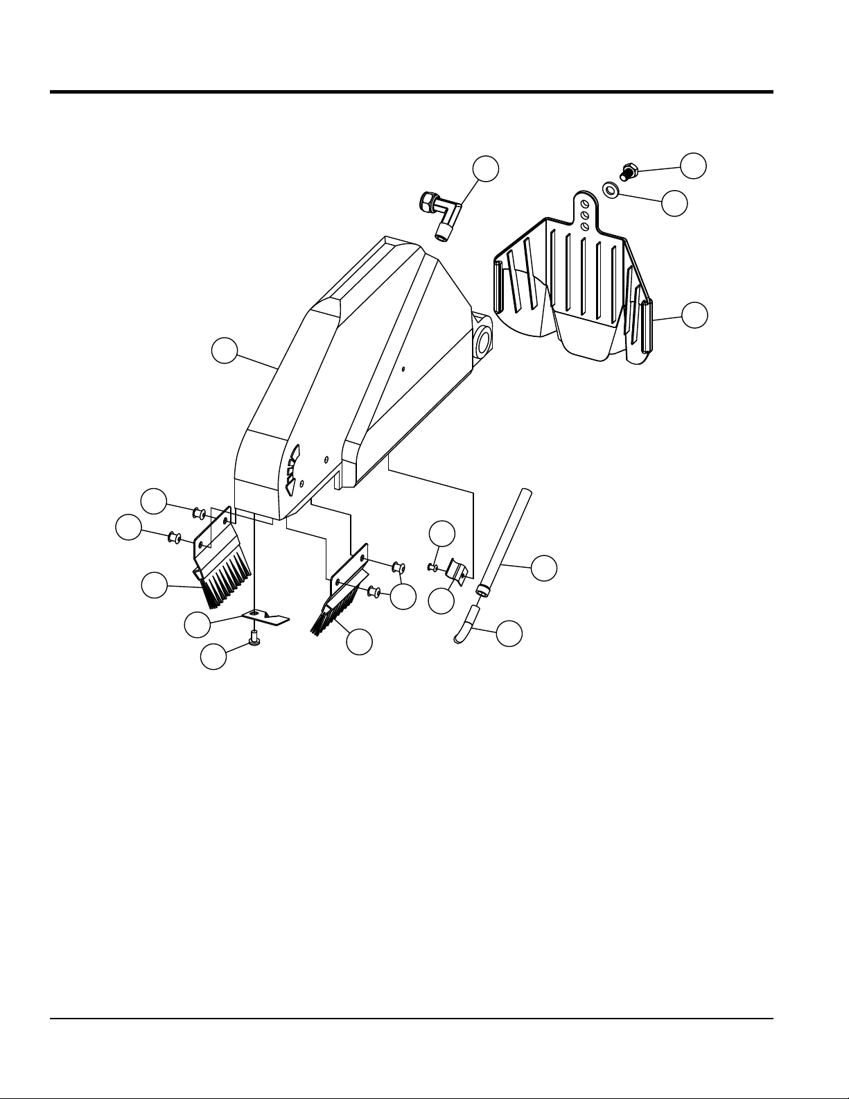
BLADE GUARD ASSY.
NO. PART NO. PART NAME QTY. REMARKS
1 TP100051 BLADE GUARD 1
2 TP100053 M3 RIVET 1
3 TP100054 PLASTIC BRUSHES 2
4 TP100055 RETAINING CLIP 1
5 TP100056 WATER BAFLE PLATE 1
6 TP110057 WATER TUBE 1
7 TP100058 D6.4MM 90° ELBOW PIPE 1
8 TP100059 D8 90° ELBOW HOSE CONNECTOR 1
9 TP100060 RUBBER SPLASH GUARD 1
10 TP481101 M5 RIVET 4
11 TP100061 WASHER NARROW M6 3
12 TP0322 HEX BOLT M6X1.0X10L 3
13 TP0353 CROSS SCREW M4X0.7X8L 1
TP24 TILE SAW • OPERATION AND PARTS MANUAL — REV. #2 (04/12/12) — PAGE 45
Page 46

BEARING HOUSING ASSY.
12
15
7
13
1
16
6
10
5
3
4
9
14
5
2
11
8
PAGE 46 — TP24 TILE SAW • OPERATION AND PARTS MANUAL — REV. #2 (04/12/12)
Page 47

BEARING HOUSING ASSY.
NO. PART NO. PART NAME QTY. REMARKS
1 TP100110 BEARING HOUSING 1
2 TP100112 BLADE SHAFT 1
3 TP100113 RUBBER GASKET 1
4 TP100114 WATER CHANNEL COVER 1
5 TP100116 MALE CONNECTOR, M10 TO D7.5 2
6 TP110017 WATER LINK ASM 1
7 TP100118 BLADE SHAFT PULLEY 1
8 TP100119 INNER ARBOR FLANGE 1
9 TP1374 CROSS SCREW M4X0.7X8L 4
10 TP100120 BEARING RADIAL D40 1
11 TP100121 BEARING RADIAL D47 1
12 TPS1000062 KEY, SQUARE 5X5X30L 1
13 TP0316 SET SCREW FLAT PT M6X1.0X10L 1
14 TP100122 HOSE, BLADE GUARD 1
15 TP100123 HOSE, WATER PUMP 1
16 TP100124 M17 E-CLIP 1
TP24 TILE SAW • OPERATION AND PARTS MANUAL — REV. #2 (04/12/12) — PAGE 47
Page 48

17
SWITCH BOX ASSY.
15
6
13
14
9
7
5
10
16
4
3
11
10
1
12
PAGE 48 — TP24 TILE SAW • OPERATION AND PARTS MANUAL — REV. #2 (04/12/12)
2
Page 49

SWITCH BOX ASSY.
NO. PART NO. PART NAME QTY. REMARKS
1@ TP420280 SWITCH BOX HOUSING 1
2@ TP420281 2 CABLE D9 CABLE GROMMET 1
3@ TP420282 2 CABLE D9 CABLE BOOT 1
4@ TP420283 CABLE CLAMP 1
5@ TPS100003 SWITCH, TOGGLE 15A 1
6@ TPS100004 CIRCUIT BREAKER RESET 20A 1
7@ TP420286 SWITCH BOX COVER 1
9@ TP110032 SCREW CROSS M3X0.5X8L 2
10@ TP1374 SCREW CROSS M4X0.7X8L 6
11@ TP420290 JUNCTION BOX 1
12@ TP03531 SCREW CROSS M4X0.7X15L 2
13@ TP420291 SHIELD POWER SWITCH 1
14@ TPS1000032 BOOT POWER SWITCH 1
15@ TPS1000041 BOOT RESET BUTTON 1
16@ TP420294 NUT, M4 X 0.7 2
17 TP100076 POWER SWITCH ASSY ....................................1................INCLUDES ITEMS W/@
TP24 TILE SAW • OPERATION AND PARTS MANUAL — REV. #2 (04/12/12) — PAGE 49
Page 50
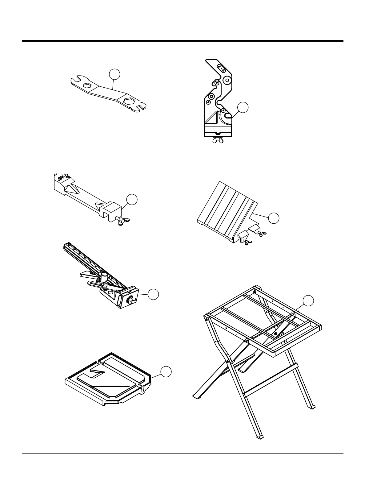
TOOLS AND ACCESSORIES
1
2
3
4
5
7
6
PAGE 50 — TP24 TILE SAW • OPERATION AND PARTS MANUAL — REV. #2 (04/12/12)
Page 51

TOOLS AND ACCESSORIES
NO. PART NO. PART NAME QTY. REMARKS
1 TPS100041 UNIVERSAL WRENCH 1
2 TPS1000MG1 MASTER GUIDE TEMPLATE BASE ..................1................OPTIONAL
3 TPS100035 45°/90° RIP GUIDE 1
4 TPS100034 MITER BLOCK ...................................................1................OPTIONAL
5 TPS1000MG MASTER GUIDE ................................................1................OPTIONAL
6 TP100102 SIDE EXTENSION TABLE .................................1................OPTIONAL
7 TPSDT1010ST SAW STAND ......................................................1................OPTIONAL
TP24 TILE SAW • OPERATION AND PARTS MANUAL — REV. #2 (04/12/12) — PAGE 51
Page 52

TERMS AND CONDITIONS OF SALE — PARTS
PAYMENT TERMS
5. Par ts must be in new and resalable
Multiquip reserves the right to quote and
who use our products as integral parts of their
LIMITATIONS OF SELLER’S LIABILITY
liable for loss of profi t or good will or for any
connection with the sale of its products. Apart
statutory, which extend beyond the description
Terms of payment for parts are net 30 days.
FREIGHT POLICY
All parts orders will be shipped collect or
prepaid with the charges added to the invoice.
All shipments are F.O.B. point of origin.
Multiquip’s responsibility ceases when a
signed manifest has been obtained from the
carrier, and any claim for shortage or damage
must be settled between the consignee and
the carrier.
MINIMUM ORDER
The minimum charge for orders from Multiquip
is $15.00 net. Customers will be asked for
instructions regarding handling of orders not
meeting this requirement.
RETURNED GOODS POLICY
Return shipments will be accepted and
credit will be allowed, subject to the following
provisions:
1. A Retu rned Mat er ia l Auth or iz atio n
must be approved by Multiquip prior to
shipment.
2. To obtain a Return Material Authorization,
a list must be provided to Multiquip
Parts Sales that defi nes item numbers,
quantities, and descriptions of the items
to be returned.
a. The parts numbers and descriptions
b. The list must be typed or computer
c. The list must state the reason(s)
d. The list must reference the sales
e. The list must include the name
3. A copy of the Return Material Authorization
must accompany the return shipment.
4. Freight is at the sender’s expense. All
parts must be returned freight prepaid to
Multiquip’s designated receiving point.
must match the current parts price
list.
generated.
for the return.
ord er(s) or in vo i ce (s) u nder
which the items were originally
purchased.
and phone number of the person
requesting the RMA.
co nd it io n, in the original Mul ti quip
package (if any), and with Multiquip part
numbers clearly marked.
6. The following items are not returnable:
a. Obsolete parts. (If an item is in the
price book and shows as being
replace d by ano ther item, it is
obsolete.)
b. Any parts with a limited shelf life
(such as gaskets, seals, “O” rings,
and other rubber parts) that were
purchased more than six months
prior to the return date.
c. Any line item with an extended
deale r n et pr ice of less th an
$5.00.
d. Special order items.
e. Electrical components.
f. Paint, chemicals, and lubricants.
g. Decals and paper products.
h. Items purchased in kits.
7. The sender will be notifi ed of any material
received that is not acceptable.
8. Such material wil l be held for five
working days from notifi cation, pending
instructions. If a reply is not received
within five days, the material will be
returned to the sender at his expense.
9. Credit on returned parts will be issued
at dealer net price at time of the original
purch ase , l ess a 15 % restoc k in g
charge.
10. In cases where an item is accepted, for
which the original purchase document
can not be determined, the price will be
based on the list price that was effective
twelve months prior to the RMA date.
11. Credit issued will be applied to future
purchases only.
PRICING AND REBATES
Prices are subject to change without prior
notice. Price changes are effective on a
specifi c date and all orders received on or
after that date will be billed at the revised price.
Rebates for price declines and added charges
for price increases will not be made for stock
on hand at the time of any price change.
sell direct to Government agencies, and to
Original Equipment Manufacturer accounts
own products.
SPECIAL EXPEDITING SERVICE
A $ 35.00 surcharge will be added to the
invoice for special handling including bus
shipments, insured parcel post or in cases
where Multiquip must personally deliver the
parts to the carrier.
Multiquip shall not be liable hereunder for
damages in excess of the purchase price of
the item with respect to which damages are
claimed, and in no event shall Multiquip be
other special, consequential or incidental
damages.
LIMITATION OF WARRANTIES
No warr an ties, express or implied, are
made in connection with the sale of parts or
trade accessories nor as to any engine not
manufactured by Multiquip. Such warranties
made in connection with the sale of new,
complete units are made exclusively by a
statement of warranty packaged with such
units, and Multiquip neither assumes nor
authorizes any per son to ass ume for it
any other obligation or liability whatever in
from such written statement of warranty,
there are no warranties, express, implied or
of the products on the face hereof.
Effective: February 22, 2006
PAGE 52 — TP24 TILE SAW • OPERATION AND PARTS MANUAL — REV. #2 (04/12/12)
Page 53

NOTES
TP24 TILE SAW • OPERATION AND PARTS MANUAL — REV. #2 (04/12/12) — PAGE 53
Page 54

OPERATION AND PARTS MANUAL
HERE’S HOW TO GET HELP
© COPYRIGHT 2012, MULTIQUIP INC.
Multiquip Inc
of their respective owners and used with permission.
This manual
The information and specifications included in this publication were in effect at the time of approval for printing. Illustrations, descriptions, references and technical data contained in
this manual are for guidance only and may not be considered as binding. Multiquip Inc. reserves the right to discontinue or change specifications, design or the information published
in this publication at any time without notice and without incurring any obligations.
PLEASE HAVE THE MODEL AND SERIAL
NUMBER ON-HAND WHEN CALLING
United StateS
Multiquip Corporate Office MQ Parts Department
18910 Wilmington Ave.
Carson, CA 90746
Contact: mq@multiquip.com
Service Department Warranty Department
800-421-1244
310-537-3700
Technical Assistance
800-478-1244 Fax: 310-943-2238
Tel. (800) 421-1244
Fax (800) 537-3927
Fax: 310-537-4259 800-421-1244
800-427-1244
310-537-3700
310-537-3700
Fax: 800-672-7877
Fax: 310-637-3284
Fax: 310-943-2249
mexico United Kingdom
MQ Cipsa Multiquip (UK) Limited Head Office
Carr. Fed. Mexico-Puebla KM 126.5
Momoxpan, Cholula, Puebla 72760 Mexico
Contact: pmastretta@cipsa.com.mx
Tel: (52) 222-225-9900
Fax: (52) 222-285-0420
Unit 2, Northpoint Industrial Estate,
Globe Lane,
Dukinfield, Cheshire SK16 4UJ
Contact: sales@multiquip.co.uk
Canada
Multiquip
4110 Industriel Boul.
Laval, Quebec, Canada H7L 6V3
Contact: jmartin@multiquip.com
Tel: (450) 625-2244
Tel: (877) 963-4411
Fax: (450) 625-8664
Tel: 0161 339 2223
Fax: 0161 339 3226
, the MQ logo are registered trademarks of Multiquip Inc. and may not be used, reproduced, or altered without written permission. All other trademarks are the proper ty
MUST accompany the equipment at all times. This manual is considered a permanent part of the equipment and should remain with the unit if resold.
Your Local Dealer is:
 Loading...