

Page 1

PARTS AND OPERATION MANUAL
OPERATION AND PARTS MANUAL
WHISPERWELD
TM
SERIES
MODEL TLW-300SS
WELDER/AC GENERATOR
(KUBOTA D722EB DIESEL ENGINE)
Revision # 2 (04/07/10)
To find the latest revision of this
publication, visit our website at:
www.mqpower.com
THIS MANUAL MUST ACCOMPANY THE EQUIPMENT AT ALL TIMES.
Page 2

PROPOSITION 65 WARNING
Diesel engine exhaust and some of
PAGE 2 — TLW-300SS WELDER/AC GENERATOR — OPERATION AND PARTS MANUAL — REV. #2 (04/07/10)
Page 3

NOTE PAGE
TLW-300SS DC WELDER/ AC GENERATOR— OPERATION AND PARTS MANUAL— REV. #2 (04/07/10) — PAGE 3
Page 4

TABLE OF CONTENTS
Proposition 65 Warning ........................................... 2
Table of Contents .................................................... 4
Parts Ordering Procedure ....................................... 5
Rules for Safe Operation ..................................... 6-7
Operation and Safety Decals ............................... 8-9
Specifications ........................................................ 10
General Information .............................................. 11
Dimensions ........................................................... 12
Trailer Safety Guidelines .................................. 13-17
Trailer Wiring Diagram........................................... 18
Towing ................................................................... 19
Controls and Indicators .................................... 20-21
Output Terminal Overview ..................................... 22
Installation ............................................................. 23
Preset ............................................................... 24-26
Instrumentation ..................................................... 27
Load Application ................................................... 28
Welder Operation Instructions ......................... 29-30
Engine Operation Instructions .............................. 31
Maintenance .................................................... 32-33
Gen. Wiring Diagram (S/N 5308736~Below) ........ 34
Gen. Wiring Diagram (S/N 5308737~Above) ....... 35
Engine Wiring Diagram (S/N 5308736~Below) .... 36
Engine Wiring Diagram (S/N 5308737~Above) ... 37
Troubleshooting-Engine ................................... 38-40
Troubleshooting-Welder ........................................ 41
Explanation of Codes in Remarks Section............ 42
Spare Parts ........................................................... 43
TLW-300SS WELDER/
AC GENERATOR
Generator Assembly ........................................ 44-46
Control Box Assembly ...................................... 46-49
Control Parts Assembly, part 1 ........................ 50-51
Control Parts Assembly, part 2 ........................ 52-53
Engine and Radiator Assembly ........................ 54-55
Battery Assembly ............................................. 56-57
Muffler Assembly ............................................. 58-59
Fuel Tank Assembly ......................................... 60-61
Enclosure Assembly ......................................... 62-65
Rubber Seals Assembly ................................... 66-67
Decal Assembly ............................................... 68-69
KUBOTA D722EB ENGINE
Crankcase Assembly ....................................... 70-71
Oil Pan Assembly ............................................. 72-73
Cylinder Head Assembly .................................. 74-75
Gear Case Assembly ....................................... 76-77
Air Cleaner Assembly ....................................... 78-79
Inlet Manifold Assembly ................................... 80-81
Exhaust Manifold Assembly ............................. 82-83
Rocker Arm Valve Assembly ............................ 84-85
Head Cover Assembly ..................................... 86-87
Dip Stick Assembly ........................................... 88-89
Main Bearing Assembly ................................... 90-91
Camshaft Assembly ......................................... 92-93
Piston and Crankshaft Assembly ..................... 94-95
Flywheel Assembly .......................................... 96-97
Fuel Camshaft Assembly ................................. 98-99
Nozzleholder Assembly................................ 100-103
Nozzleholder Glow Plug Assembly .............. 104-105
Injection Pump Assembly ............................. 106-107
Injection Pump Comp. Assembly ................. 108-109
Fuel Filter Assembly .................................... 110-111
Fuel Pump Assembly ................................... 112-113
Governor Assembly ..................................... 114-115
Speed Control Plate Assembly .................... 116-117
Stop Solenoid Assembly .............................. 118-119
Starter Assembly ......................................... 120-121
Starter Comp. Assembly .............................. 122-123
Dynamo Assembly ....................................... 124-125
Water Flange Assembly ............................... 126-127
Water Pump Assembly ................................. 128-129
Water Pipe Assembly ................................... 130-131
Starter Switch Assembly .............................. 132-133
Piston Kit and Accessories ........................... 134-135
Terms and Conditions - Sale ............................... 136
NOTE
Specification and part number
are subject to change without
notice.
PAGE 4 — TLW-300SS WELDER/AC GENERATOR — OPERATION AND PARTS MANUAL — REV. #2 (04/07/10)
Page 5

r
Best Deal!
PARTS ORDERING PROCEDURES
Ordering parts has never been easier!
Choose from three easy options:
Order via Internet
Order parts on-line using Multiquip’s SmartEquip website!
N View Parts Diagrams
N Order Parts
N Print Specification Information
(Dealers Only)
:
If you have an MQ Account, to obtain a Username
and Password, E-mail us at: parts@multiquip.
com.
To obtain an MQ Account, contact you
District Sales Manager for more information.
January 1
Effective:
st
, 2006
Goto www.multiquip.com and click on
Order Par ts
Order via Fax
All customers are welcome to order parts via Fax.
Domestic (US) Customers dial:
1-800-6-PARTS-7 (800-672-7877)
to log in and save!
(Dealers Only)
:
Order via Phone:
Non-Dealer Customers:
Contact your local Multiquip Dealer for
parts or call 800-427-1244 for help in
locating a dealer near you.
When ordering parts, please supply:
R Dealer Account Number
R Dealer Name and Address
R Shipping Address (if different than billing address)
R Return Fax Number
R Applicable Model Number
R Quantity, Part Number and Description of Each Part
Use the internet and qualify for a 5% Discount
on Standard orders for all orders which include
complete part numbers.*
Fax your order in and qualify for a 2% Discount
on Standard orders for all orders which include
complete part numbers.*
Domestic (US) Dealers Call:
1-800-427-1244
International Customers should contact
their local Multiquip Representatives for
Parts Ordering information.
R Specify Preferred Method of Shipment:
UPS/Fed Ex DHL
N Priority One Truck
N Ground
N Next Day
N Second/Third Day
Note: Discounts Are Subject To Change
Note: Discounts Are Subject To Change
NOTICE
All orders are treated as Standard Orders and will
ship the same day if received prior to 3PM PST.
www.mqpower.com
WE ACCEPT ALL MAJOR CREDIT CARDS!
TLW-300SS DC WELDER/ AC GENERATOR— OPERATION AND PARTS MANUAL— REV. #2 (04/07/10) — PAGE 5
Page 6

RULES FOR SAFE OPERATION
CAUTION:CAUTION:
CAUTION:
CAUTION:CAUTION:
Failure to follow instructions in this manual may
lead to serious injury or even death! This
equipment is to be operated by trained and
qualified personnel only! This equipment is for
industrial use only.
The following safety guidelines should always be used when
operating the TLW-300SS Welder/AC Generator:
GENERAL SAFETY
■
DO NOT operate or service this equipment before
reading this entire manual.
■
This equipment should not be operated by
persons under 18 years of age.
■
NEVER operate this equipment without proper
protective clothing, welding shield, ventilator,
steel-toed boots and other protective devices
required by the job.
■
NEVER touch the hot exhaust
manifold, muffler or cylinder. Allow
these parts to cool before servicing
engine or welder/AC generator.
■
High Temperatures – Allow the engine to cool before adding
fuel or performing service and maintenance functions. Contact
hot
with
■
The engine of this welder/AC generator requires an adequate
free flow of cooling air. Never operate the welder/AC generator
in any enclosed or narrow area where free flow of the air is
components can cause serious burns.
restricted. If the air flow is
restricted it will cause serious
damage to the welder/AC
generator engine and may
cause injury to people. The
engine gives off DEADLY
carbon monoxide gas.
■
NEVER operate this equipment when not feeling
well due to fatigue, illness or taking medicine.
■
■
NEVER operate this equipment under the
influence or drugs or alcohol.
■
NEVER use accessories or attachments, which are not
recommended by MQ Power for this equipment. Damage to
the equipment and/or injury to user may result.
■
Manufacture does not assume responsibility for any accident
due to equipment modifications.
■
Whenever necessary, replace nameplate, operation and
safety decals when they become difficult read.
■
Always check the machine for loosened threads or bolts before
starting.
■
■
Always refuel in a well-ventilated area, away from sparks and
open flames.
Always use extreme caution when
working with flammable liquids. When
refueling, stop the engine and allow it
to cool. DO NOT
the machine. Fire or explosion could
result from fuel vapors, or if fuel is spilled
on a hot engine.
NEVER operate the welder/AC generator in an explosive
atmosphere or near combustible materials. An explosion or
fire could result causing severe
Topping-off to filler port is dangerous, as it tends to spill fuel.
smoke around or near
bodily harm or even death.
PAGE 6 — TLW-300SS WELDER/AC GENERATOR — OPERATION AND PARTS MANUAL — REV. #2 (04/07/10)
Page 7

CAUTIONCAUTION
CAUTION
CAUTION:CAUTION:
CAUTION:
CAUTION:CAUTION:
This welder/AC generator is a source of
providing LETHAL high voltages. Never
permit unqualified personnel-especially
children to operate the welder/AC generator.
■
This welder/AC generator is equipped with a
for your protection. Always complete the grounding path from
the welder/AC generator to an external grounding source.
■
NEVER operate this welder/AC generator, or handle any
electrical equipment while standing in
while hands are wet, or in the rain. Dangerous electrical
shock could occur causing severe bodily harm or even death.
■
This welder/AC generator requires an adequate free flow of
cooling air. Never operate the welder/AC generator in any
enclosed or narrow area where free flow of the air is restricted.
If the air flow is restricted it will cause serious damage to the
welder/AC generator and may cause injury to people.
■
Arc rays can cause blindness. Always wear protective
shield when welding.
CAUTIONCAUTION
CAUTION
CAUTIONCAUTION
:
ground terminal
water, while bare foot,
CAUTIONCAUTION
■
Never use damaged or worn cables when connecting
power tools or equipment to the welder/AC generator.
Make sure power connecting cables are securely
connected to the generator’s output terminals. Insufficient
tightening of the terminal connections may cause damage
to the welder/AC generator and electrical shock.
CAUTIONCAUTION
CAUTION
CAUTIONCAUTION
RULES FOR SAFE OPERATION
:
:
DO NOT touch or open coolant drain plug,
radiator cap, or engine oil drain plug while
the welder/AC generator is running.
Always allow sufficient time for the engine
and generator to cool before performing
maintenance.
Emergencies
■
and
Also know the phone numbers of the nearest
■
NEVER touch output terminals or electrode during
operation. This is extremely dangerous. Always stop the
machine when contact with the output terminals and
welding electrode.
CAUTIONCAUTION
CAUTION
CAUTIONCAUTION
■
Never connect the welder/AC generator to house wiring.
This is illegal and very dangerous. Electrical shock could
occur causing damage to the welder/AC generator and
bodily harm even death.
:
doctor
in the case of an emergency.
Maintenance Safety
■
■
■
■
■
■
■
Always know the location of the nearest
first aid kit
and
NEVER lubricate components or attempt service on a running
machine.
Always allow the machine a proper amount of time to cool
before servicing.
Keep the machinery in proper running condition.
Fix damage to the machine immediately and always replace
broken parts.
Dispose of hazardous waste properly. Examples of potentially
hazardous waste are used motor oil, fuel, coolant and fuel
filters.
DO NOT use plastic containers to dispose of hazardous
waste.
DO NOT pour waste, oil, coolant or fuel directly onto the
ground, down a drain or into any water source.
. Know the location of the nearest telephone.
fire department
. This information will be invaluable
fire extinguisher
ambulance
,
TLW-300SS DC WELDER/ AC GENERATOR— OPERATION AND PARTS MANUAL— REV. #2 (04/07/10) — PAGE 7
Page 8

OPERATION AND SAFETY DECALS
Machine Safety Decals
The TLW-300SS welder/AC generator is equipped with a number of safety decals. These decals are provided for operator safety
and maintenance information. The illustration below shows these decals as they appear on the machine. Should any of these decals
become unreadable, replacements can be obtained from your dealer.
PAGE 8 — TLW-300SS WELDER/AC GENERATOR — OPERATION AND PARTS MANUAL — REV. #2 (04/07/10)
Page 9

OPERATION AND SAFETY DECALS
P/N DCL160
TLW-300SS DC WELDER/ AC GENERATOR— OPERATION AND PARTS MANUAL— REV. #2 (04/07/10) — PAGE 9
Page 10

ledoMSS003-WLB
epyTrotarenegepytdleif,gnivlover,sselhsurB
tnerruCdetaRA082
egatloVdetaRV52/V2.13
TLW-300SS — SPECIFICATIONS
snoitacificepS.1elbaT
snoitacificepSredleW
aRA003~53
taRmpr0063/PH8.81
tnerruCfoegn
elcyCytuD%001/%05
ycneuqerFzH06
deepSmpr0063
tuptuO.xaMWk5.01
tuptuOdetaRWk0.01
egatloVV042/021
ledoMBE227DATOBUK
epyTlacitrev,elcyC4
srednilyCfo.oNsrednilyc3
ekortSxeroB)mm86xmm76(.ni86.2x.ni46.2
tuptuOde
tnemecalpsiD)cc917(.ni.uc9.34
snoitacificepSrotareneG
snoitacificepSenignE
gnitratScirtcelE
yticapaCtnalooC)sretil1.2(.lag55.
OebuL)sretil51.3(.lag38.
yticapaCli
noitpmusnoCleuF
yticapaCleuF)sret
epytleuFleuFleseiD2#
yrettaBHA54-V21
.lag66.gnidleW rh/)L5.2(
.lag41.1rewoPCA rh/)L3.4(
il63(lag5.9.xorppA
The maximum output of the engine listed above is applicable to supplying electrical power for continuous service at ambient
conditions in accordance with SAE Test cord J607. The above ambient conditions are at standard sea level, with a barometric
reading of 29.92 inches and a temperature of 60 degrees Fahrenheit.
°°
°
°°
Generally, the engine output power will decrease 3 1/2% for each 1000 feet of altitude above sea level, and 1% for each 10
°°
°
Fahrenheit above the standard temperature of 60
°°
F.
F
PAGE 10 — TLW-300SS WELDER/AC GENERATOR — OPERATION AND PARTS MANUAL — REV. #2 (04/07/10)
Page 11

TLW-300SS — GENERAL INFORMATION
TLW-300SS FAMILIARIZATION
Generator
The MQ Power Model TLW-300SS welder/AC generator can
provide 280 amps of welding current. When used as a
generator, can provide a maximum of 10 kilowatts of power.
Control Panel
control panel
The
One GFCI 120 volt receptacle, 20 amp
One 120 volt receptacle, 30 amp
One 120/240 volt receptacle, 30 amp
Circuit Protector Breaker (GFCI) 120V @20 Amps
Idle Control Switch
Main Circuit Breaker, 42A
Starter Switch
Warning Lamp Unit
Hour Meter
Ground Terminal
Engine Protection System
Engine protection fail safe features are provided in the event
of low oil pressure, high coolant temperature and failure of
the battery to charge. If any of the above conditions occur
while operating the welder/AC generator, it will cause a
complete unit shut down.
is provided with the following:
Excitation System
The TLW-300SS Welder/AC generator uses a brushless
exciter to create rated output electricity. This system will
use the mechanical energy generated by the 3600 RPM
engine to spin the rotor (or armature) inside the welder/AC
generator (or alternator end).
The motion created by the rotor (which holds copper coils)
spins inside a housing pf permanent magnets called the
"STATOR". A magnetic field is created by the stator and
produces an electrical current.
Engine
The TLW-300SS is powered by a 4-cycle KUBOTA
engine. This engine is designed to meet every performance
requirement for welder/AC generator. Reference Table 1, page
10 for engine specifications.
In keeping with MQ Power's policy of constantly improving
its products, the specifications quoted herein are subject to
change without prior notice.
Figures 2 and 3 (pages 13-14) show the basic controls and
indicators for the TLW-300SS Welder/AC generator.
diesel
Battery Charge Indicator
This unit is equipped with a protective device that signals
an indicator and automatically stops the engine when the
battery cannot be charged by the alternator.
Water Temperature Indicator
This unit is equipped with an apparatus that signals an
indicator and automatically stops the engine when the cooling
water temperature becomes abnormally high. This apparatus
will not function properly if the machine is operated with
less than the proper amount of coolant.
Oil Pressure Warning Indicator
In the event of low oil pressure (engine), this welder/AC
generator is equipped with an engine protection fail safe
system . If low oil pressure is detected while operating the
welder/AC generator, the engine protection system will shut
down the engine.
If this condition (low oil pressure) should occur, please refer
to the engine troubleshooting table (page 28) in this manual.
TLW-300SS DC WELDER/ AC GENERATOR— OPERATION AND PARTS MANUAL— REV. #2 (04/07/10) — PAGE 11
Page 12
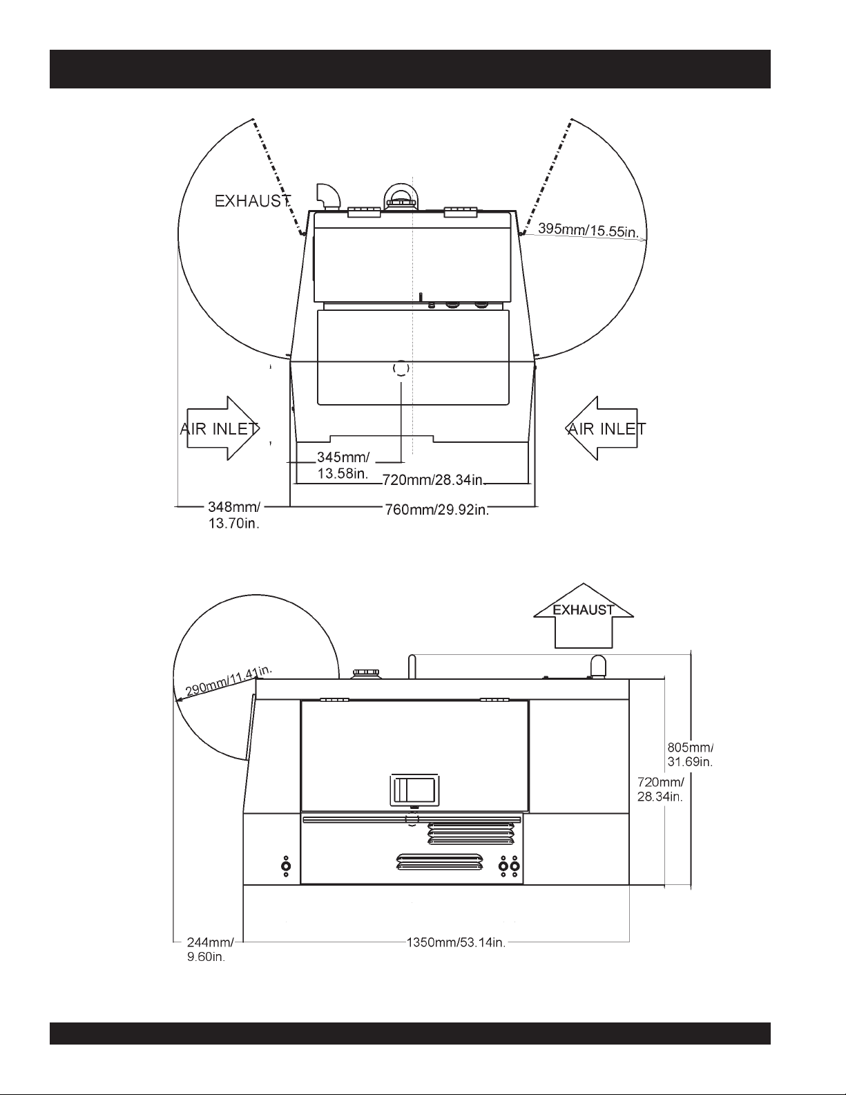
TLW-300SS — DIMENSIONS
Figure 1. TLW-300SS Dimensions
PAGE 12 — TLW-300SS WELDER/AC GENERATOR — OPERATION AND PARTS MANUAL — REV. #2 (04/07/10)
Page 13

TLW-300SS — TRAILER-SAFETY GUIDELINES
CAUTION:CAUTION:
CAUTION:
CAUTION:CAUTION:
ALWAYS make sure the trailer is in good
operating condition. Check the tires for
proper inflation and wear. Also check the
wheel lug nuts for proper tightness.
Explanation of Chart:
This section is intended to provide the user with trailer service and maintenance information. The service and maintenance guidelines referenced in this section apply a wide
range of trailers. Remember periodic inspection of the trailer
will ensure safe towing of the equipment and will prevent
damage to the equipment and personal injury.
It is the purpose of this section to cover the major maintenance components of the trailer. The following trailer components will be discussed in this section:
Brakes
Tires
Lug Nut Torquing
Suspension
Electrical
Brake Troubleshooting Tables
Use the following definitions with reading Table 2.
1. Fuel Cell - Provides an adequate amount of fuel for
the equipment in use. Fuel cells must be empty when
transporting equipment.
2. Braking System - System employed in stopping the
trailer. Typical braking systems are electric, surge, hydraulic, hydraulic-surge and air.
3. GVWR- Gross Vehicle Weight Rating (GVWR), is the
maximum number of pounds the trailer can carry, including the fuel cell (empty).
4. Frame Length - This measurement is from the ball
hitch to the rear bumper (reflector).
5. Frame Width - This measurement is from fender to
fender.
6. Jack Stand - Trailer support device with maximum
pound requirement from the tongue of the trailer.
7. Coupler - Type of hitch used on the trailer for towing.
8. Tire Size - Indicates the diameter of the tire in inches
(10,12,14, etc.), and the width in millimeters
(175,185,205, etc.). The tire diameter must match the
diameter of the tire rim.
9. Tire Ply - The tire ply (layers) number is rated in letters;
2-ply,4-ply,6-ply, etc.
10. Wheel Hub - The wheel hub is connected to the trailer’s
axle.
11. Tire Rim - Tires mounted on a tire rim. The tire rim must
match the size of the tire.
12. Lug Nuts - Used to secure the wheel to the wheel hub.
Always use a torque wrench to tighten down the lug
nuts. See Table 4 and Figure 5 or lug nut tightening and
sequence.
13. Axle - Indicates the maximum weight the axle can support in pounds, and the diameter of the axle expressed
in inches (see Table 3). Please not that some trailers
have a double axle. This will be shown as 2-6000 lbs.,
meaning two axles with a total weight capacity of 6000
pounds.
14. Suspension - Protects the trailer chassis from shocks
transmitted through the wheels. Types of suspension
used are leaf, Q-flex, and air ride.
15. Electrical - Electrical connectors (looms) are provided
with the trailer so the brake lights and turn signals can
be connected to the towing vehicle.
16. Application - Indicates which units can be employed
on a particular trailer.
TLW-300SS DC WELDER/ AC GENERATOR— OPERATION AND PARTS MANUAL— REV. #2 (04/07/10) — PAGE 13
Page 14

TLW-300SS — TRAILER-SPECIFICATIONS
Table 1. Specifications
MODEL APPLICATION FUEL
CELL
TRLR-10W SDW225,
SGW250,TLW300
TRLR-10 DCA10, TLG12,
DCA-15
TRLR-10XF DCA10, TLG-12,
DCA15, TLW-300
TRLR-225W WELDERS,
DA7000SS
TRLR-BLW400 BLW-400 NO ELECTRIC 2700LBS W/MAST 154"
TRLR-50X DCA-25 NO NO 2700LBS 124" 55" 800LB.
TRLR-50XF DCA-25 41 GAL NO 2700LBS 124" 55" 800LB.
TRLR-70W D CA -45, -60, 70 NO SURGE 7000LBS 186" 77" 2000LB.
TRLR-70X DCA-45, -60, 70 OPT SURGE 7000LBS 13 8" 66" 2000LB.
TRLR-70XF DCA -45, -60, 70 53 GAL SURGE 70 00LBS 138" 66" 2000LB.
TRLR-100XF DC A -100, 125 150 GAL HYDRAULIC SURGE 7000LBS 190" 76" 2000LB.
TRLR-85/125 DCA-85, 100,
125
TRLR-150XF DC A -150, 180 200 GAL HYDRAULIC SURGE 11160LBS 204" 84" 5000 LB.
TRLR-220XF DCA-220 25 0 GAL HYD RAULIC SURGE 14000LBS 222" 83" 50 00 L B .
TRLR-300XF DCA-300 25 0 GAL HYD RAULIC SURGE 18000LBS 238" 83" 50 00 L B .
TRLR-400XF DCA-400 350 GAL ELECTRIC 18000LBS 238" 83" 5000 LB.
TRLR-600XF DCA -600, 800 550 GAL AIR 30000LBS 384" 96" 5000 LB.
TRLR-800SX DCA-600, 800 550 GAL AIR 30000LBS 384" 96" 5000 LB.
NO NO 1900LBS 96" 50" 800LB.
NO NO 1900LBS 96" 50" 800LB.
52 GAL NO 1900LBS 96" 50" 800LB.
NO NO 2200LBS 85" 42" 800LB.
145 GAL HYD RAULIC 10000LBS 186" 77" 2000LB.
BRAKE
SYSTEM
GVWR FRAME
LENGTH
W/O 124"
FRAME
WIDTH
55"
(78" TALL )
JACK
STAND
FULL TILT WHEEL
FULL TILT WHEEL
FULL TILT WHEEL
FULL TILT WHEEL
800LB.
FULL TILT WHEEL
FULL TILT WHEEL
FULL TILT WHEEL
FL AT PAD
FL AT PAD
FL AT PAD
FL AT PAD
FL AT PAD
FL AT PAD
FL AT PAD
FL AT PAD
FL AT PAD
FL AT PAD
FL AT PAD
PAGE 14 — TLW-300SS WELDER/AC GENERATOR — OPERATION AND PARTS MANUAL — REV. #2 (04/07/10)
Page 15

TLW-300SS — TRAILER-SPECIFICATIONS
Table 1. Specifications (Con't)
MODEL COUPLER TIRES WHEELS AXLE HUBS SUSPENSION ELECTRICAL
TRLR-10W 2" BALL CLASS
TRLR-10 2"BALL CLASS
TRLR-10XF 2"BALL CLASS
TRLR-225W 2"BALL CLASS
TRLR-BLW
400
TRLR-50X 2" BALL CLASS B78-13LRC 13"X4.50" 3500lbs.
TRLR-50XF 2" BALL CLASS B78-13LRC 13"X4.50" 3500lbs.
TRLR-70W 2" BALL CLASS
TRLR-70X 2" BALL CLASS
TRLR-70XF 2" BALL CLASS
TRLR-100XF ADJUSTABLE 2-5/6
TRLR-85/125 ADJUSTABLE 2-5/6
TRLR-150XF 3" BALL EYE 750-16 E
TRLR-220XF 3" E YE
TRLR-300XF 3" E YE
TRLR-400XF 3" EYE
TRLR-600XF 5TH WHEEL ST215/75R17.5H
TRLR-800AR 5TH WHEEL ST215/75R17.5H
2 ADJUSTABLE
2 ADJUSTABLE
2 ADJUSTABLE
2 ADJUSTABLE
2"BALL CLASS
2 ADJUSTABLE
3" ADJUSTABLE
3" ADJUSTABLE
3" ADJUSTABLE
OPT 3" EYE
OPT 3" EYE
ADJUSTABLE
ADJUSTABLE
ADJUSTABLE
175-13C 13"X4.50" 2200# 2X2 5 LUG 3 LEAF 4 WIRE LOOM W/
175-13C 13"X4.5" 2200#2X2 5 LUG 3 LEAF 4 P OLE FLAT
175-13C 13"X4.5" 2200#2X2 5 LUG 3 LEAF 4 P OLE FLAT
175-13B 13X 4.5" 2200#2X2 5 LUG Q FLEX 4 POLE FLAT
175-13C 13 X 4.5" 2200#2X2 5 LUG 3 LEAF 4 POLE FLAT
5 LUG 4 LEAF 4 POLE RUBBER
5 LUG 4 LEAF 4 POLE RUBBER
5 LUG 5 LEAF 4 POLE RUBBER
5 LUG 5 LEAF 4 POLE RUBBER
5 LUG 5 LEAF 4 WIRE LOOM
205-14C
BIAS (4)
205-14C
BIAS (4)
205-14C
BIAS (4)
205-15C
BIAS (4)
ST225/75R15D
RADIAL (4)
BIAS (4)
ST235/85R16E
RADIAL(4)
ST235/85R16E
RADIAL(6)
ST235/85R16E
RADIAL(6)
RADIAL (8)
RADIAL (8)
2-3/8"
2-3/8"
14"X5" 3500lbs.
3"
14"X5" 3500lbs
3"
14"X5" 3500lbs.3"5 LUG 5 LEAF 4 POLE RUBBER
14"X5.5" 3500lbs
3"
14"x6" (2)-6000lbs 6 LUG 7 LE A F 4 WIRE LOOM
16"X7" (2)-6000lbs 8 LUG 7 LEAF 4 WIRE LOOM
16"X7" (2)-7000lbs 8 LUG Q FLEX 4 WIRE LOOM
16"X7" (2)-6000lbs 8 LUG Q FLEX 4 WIRE LOOM
16"X7" (3)-7000lbs. 8 LUG Q FLEX 4 WIRE LOOM
16"X7" (3)-10000lbs 8 LUG 7 LEAF 6 WIRE LOOM
16"X7" (3)-10000lbs 8 LUG AIR-RID E 6 WIRE LOOM
4 POLE FLAT
FLAT
FLAT
FLAT
FLAT
FLAT
TLW-300SS DC WELDER/ AC GENERATOR— OPERATION AND PARTS MANUAL— REV. #2 (04/07/10) — PAGE 15
Page 16

TLW-300SS —TRAILER SAFETY GUIDELINES
Tires/Wheels/Lug Nuts
Tires and wheels are a very important and critical
components of the trailer. When specifying or replacing the
trailer wheels it is important the wheels, tires, and axle are
properly matched.
CAUTION:
DO NOT attempt to repair or modify a
wheel. DO NOT install in inner tube to
correct a leak through the rim. If the rim
is cracked,
the air
pressure in
the inner tube may cause pieces
of the rim to explode (break off)
with great force and cause serious
eye or bodily injury.
Tire Wear/Inflation
Tire inflation pressure is the most important factor in tire life.
Pressure should be checked cold before operation DO NOT
bleed air from tires when they are hot. Check inflation
pressure weekly during use to insure the maximum tire life
and tread wear.
Table 3 (Tire Wear Troubleshooting) will help pinpoint the
causes and solutions of tire wear problems.
Suspension
The leaf suspension springs and associated components
(Figure 2) should be visually inspected every 6,000 miles for
signs of excessive wear, elongation of bolt holes, and
loosening of fasteners. Replace all damaged parts
(suspension) immediately. Torqued suspension components
as detailed in Table 4.
CAUTION:
Figure 2. Major Suspension Components
NOTE
ALWAYS wear safety glasses when removing
or installing force fitted parts. Failure to
comply may result in serious injury.
PAGE 16 — TLW-300SS WELDER/AC GENERATOR — OPERATION AND PARTS MANUAL — REV. #2 (04/07/10)
Page 17

metI ).sbL-.tF(euqroT
TLOB-U"8/353-XAM03-NIM
TLOB-U"61/706-XAM54-NIM
TLOB-U"2/106-XAM54-NIM
TLW-300SS —TRAILER SAFETY GUIDELINES
stnemeriuqeReuqroTnoisnepsuS.4elbaT
SHACKLE BOLT
SPRING EYE BOLT
SHOULDER TYPE
SHACKLE BOLT
SNUG FIT ONLY.PARTS MUST ROTATE FREELY
LOCKING NUTS OR COTTER PINS ARE PROVIDED TO
-
RETAIN NUT
BOLT ASSEMBLY
.
.
05-XAM03-NIM
Lug Nut Torque Requirements
It is extremely important to apply and maintain proper wheel
mounting torque on the trailer. Be sure to use only the
fasteners matched to the cone angle of the wheel. Proper
procedure for attachment of the wheels is as follows:
1. Start all wheel lug nuts by hand.
2. Torque all lug nuts in sequence. See Figure 3. DO NOT
torque the wheel lug nuts all the way down. Tighten
each lug nut in 3 separate passes as defined by Table 5.
3. After first road use, retorque all lug nuts in sequence.
Check all wheel lug nuts periodically.
stnemeriuqeReuqroTeriT.5elbaT
eziSleehWssaPtsriF
SBL-TF
ssaPdnoceS
SBL-TF
ssaPdrihT
SBL-TF
"2152-0204-5356-05
"3152-0204-5356-05
"4152-0206-05021-09
5152-0206-05021-09
"
"6152-0206-05021-09
Figure 3. Wheel Lug Nuts Tightening Sequence
NOTE
NEVER use an pneumatic air gun to
tighten wheel lug nuts.
TLW-300SS DC WELDER/ AC GENERATOR— OPERATION AND PARTS MANUAL— REV. #2 (04/07/10) — PAGE 17
Page 18

TLW-300SS —TRAILER-WIRING DIAGRAM
PAGE 18 — TLW-300SS WELDER/AC GENERATOR — OPERATION AND PARTS MANUAL — REV. #2 (04/07/10)
Page 19

TLW-300SS —TOWING
Towing Safety Precautions
CAUTION :CAUTION :
CAUTION :
CAUTION :CAUTION :
Check with your county or state safety
towing regulations department before
towing your generator. Vehicle towing
codes and regulations can vary from state
to state.
To reduce the possibility of an accident while transporting
the generator on public roads, always make sure the trailer
(Figure 4) and the towing vehicle are in good operating
condition and both units are mechanically sound.
The following list of suggestions should be used when towing
your generator:
■
Make sure the hitch and coupling of the towing vehicle are
rated equal to, or greater than the trailer "gross vehicle weight
rating" (GVWR).
■
ALWAYS inspect the hitch and coupling for wear. NEVER
tow a trailer with defective hitches, couplings, chains etc.
■
Check the tire air pressure on both the towing vehicle and
the trailer. Also check the tire tread wear on both vehicles.
■
ALWAYS make sure the trailer is equipped with a "Safety
Chain".
■
ALWAYS attach trailer's safety chain to bumper of towing
vehicle.
■
ALWAYS make sure the vehicle and trailer directional,
backup, brake, and trailer lights are connected and are
working properly.
■
The maximum speed (unless otherwise posted) for highway
towing is 45 MPH. Recommended off-road towing is not to
exceed 10 MPH or less, depending on type of terrain.
■
Place
while parked.
■
Place
prevent
■
Use the trailer's hand winch to adjust the height of the trailer,
then insert locking pin to lock wheel stand in place, while
parked.
■
Avoid sudden stops and starts. This can cause skidding, or
jackknifing. Smooth, gradual starts and stops will improve
gas milage.
■
Avoid sharp turns to prevent rolling.
■
Remove wheel stand when transporting.
■
DO NOT transport generator with fuel in tank.
chocked blocks
support blocks
tipping
underneath wheel to prevent
underneath the trailer's bumper to
, while parked.
rolling,
Figure 4. Welder/AC Generator and Towing Trailer
TLW-300SS DC WELDER/ AC GENERATOR— OPERATION AND PARTS MANUAL— REV. #2 (04/07/10) — PAGE 19
Page 20

TLW-300SS — CONTROLS AND INDICATORS
Figure 5. Controls and Indicators
PAGE 20 — TLW-300SS WELDER/AC GENERATOR — OPERATION AND PARTS MANUAL — REV. #2 (04/07/10)
Page 21

TLW-300SS — CONTROLS AND INDICATORS
Figure 5 shows the location of the controls and indicators. The
functions of each control or indicator is described below.
1. Voltage Regulator- Controls the Voltage for welding/load.
2. AC Voltmeter- Indicated amount of voltage output.
3. Main Circuit Breaker- 2-pole, 42A will shut down current
when welder/generator is overloaded.
4. No. 1 Circuit Breaker-(S/N 5308737~)- single pole circuit
breaker will shut down current in the 240V/30A receptacle.
5. Ignition Switch with Key- Used to start and preheat engine.
6. Engine Warning Indicators- Lights red when the following
conditions occur:
Low Oil Pressure
High Water Temperature
Electrical System Is Not Charging Properly
7. Hour Meter – Indicates number of hours machine has
been in use or hours engine was run.
8. Idle Switch- Turn on for rpms to automatically adjust rpms
when a load is added.
9. No. 3 Circuit Breaker-(S/N 5308737~)- single pole circuit
breaker will shut down current in the 120V/20A receptacle.
10. No. 2 Circuit Breaker-(S/N 5308737~)- single pole circuit
breaker will shut down current in the 120V/30A receptacle.
11. Positive Welding Output Terminal- Positive connection
for welding.
12. Negative Welding Output Terminal-Negative connection
for welding.
13. G.F.C.I. Ground Terminal- Used to ground GFCI
receptacle.
14. G.F.C.I. Receptacle- 120V/20A receptacle for smaller
power applications.
15. 120V Receptacles- used for 20 or 30 amp power
applications.
16. 240V Receptacle- used for 30 amp power applications.
TLW-300SS DC WELDER/ AC GENERATOR— OPERATION AND PARTS MANUAL— REV. #2 (04/07/10) — PAGE 21
Page 22
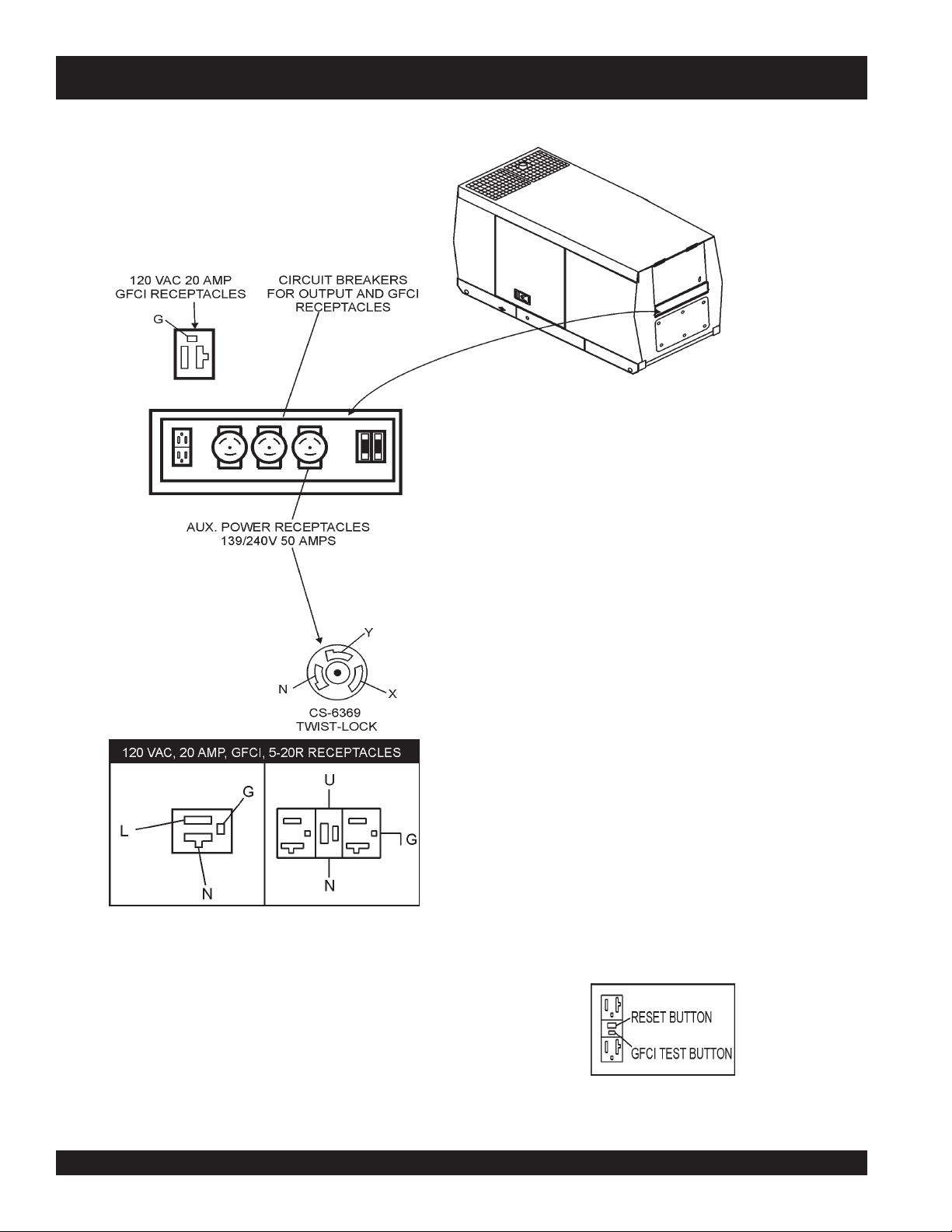
TLW-300SS — OUTPUT TERMINAL OVERVIEW
Figure 7. Duplex Receptacle Detail
Figure 6. Output Terminal Panel
120 Volt Receptacle
One GFCI Duplex Nema 5-20R (120V, 20 Amp) receptacle
is provided on the output terminal. This receptacle can be
used anytime the generator is in operation. The receptacle
is controlled by the circuit breaker located on the control
panel.
The reset button is for the GFCI when the circuit is tripped.
Pressing the "Test Button" (See Figure 8) in the center of
this receptacle will check the GFCI function. The receptacle
should be tested at least once a month.
Figure 8. GFCI Test Button
PAGE 22 — TLW-300SS WELDER/AC GENERATOR — OPERATION AND PARTS MANUAL — REV. #2 (04/07/10)
Page 23

TLW-300SS — INSTALLATION
Outdoor Installation
Install the welder/AC generator in a location where it will not
be exposed to rain or sunshine. Make sure the Welder/AC
generator is on secure level ground so it cannot slide or
shift around. Also install the welder/AC generator so the
exhaust will not be discharged in the direction of nearby
homes.
The installation site must be relatively free from moisture
and dust. All electrical equipment should be protected from
excessive moisture. Failure to do will result in deterioration
of the insulation, and will result in short circuits.
Foreign materials such as dust, sand, lint and abrasive
materials will cause excessive wear to engine and alternator
parts.
CAUTION :CAUTION :
CAUTION :
CAUTION :CAUTION :
Pay close attention to ventilation when
operating the welder/AC generator inside
tunnels and caves. The engine exhaust
contains noxious elements.
Indoor Installation
Exhaust gases from diesel engines are extremely poisonous.
Whenever an engine is installed indoors the exhaust fumes
must be vented to the outside. The engine should be installed
at least two feet from any outside wall. Using an exhaust
pipe which is too long or too small can cause excessive
back pressure and cause the engine to heat excessively.
Eliminate the danger of deadly carbon monoxide gas.
Remember that exhaust fumes from any diesel engine are
very poisonous if discharged in a closed room, but harmless
if allowed to mix with the outside air. If the welder/AC
generator is installed indoors, you must make provisions for
venting the engine exhaust to the outside of the building.
CAUTION :CAUTION :
CAUTION :
CAUTION :CAUTION :
An electric shock may happen when
vibrators are used. Pay close attention to
handling when operating vibrators and
always use rubber boots and gloves to
insulate the body from a electrical shock.
TLW-300SS DC WELDER/ AC GENERATOR— OPERATION AND PARTS MANUAL— REV. #2 (04/07/10) — PAGE 23
Page 24

TLW-300SS — PRE-SETUP
General Inspection Prior to Operation
The TLW-300SS utilizes a welder/AC generator that has
been thoroughly inspected and accepted prior to shipment
from the factory. However, be sure to check for damaged
parts or components, or loose nuts and bolts, which could
have occurred in transit.
Ground
The nut and ground terminal on the welder/AC generator
should always be used to connect to a suitable ground. The
ground path should be of #8 size wire.
Circuit Breakers
To protect the welder/AC generator from an overload,
42 amp,
separate circuit breakers are provided for each receptacle.
Be sure the circuit breakers are in the ‘OFF’ position prior to
starting the engine.
Welding Cable
When welding, use the table below (Table 6) to measure the
optimum amount of voltage and amperes when selecting the
proper welding cable. The relationship between cable length
and sectional area is to keep the line voltage drop within 4V.
Connect the terminal of the ground wire between the lock
washer and the nut and tighten the nut fully. Connect their
end of the wire to a suitable ground.
/)tf(htgneLelbaClatoT
)A(tnerruC
05001521051002052003
a 2-pole,
main
circuit breaker is provided. In addition, three
seziSelbaCgnidleW.6elbaT
0013#3#3#3#3#3#3#
0513#3#3#3#2#1#1#
0023#3#2#1#0/1#0/2#0/3#
0523#2#1#0/1#0/2#0/3#0/3#
DC Welding/AC Power
This unit will provide simultaneous use of DC welding power
and AC Power. Use the table below (Table 7) when selecting
electrode size for the amount of AC power provided.
yticapaCrewoPCA/gndleWCD.7elbaT
EZISEDORTCELEGNIDLEWYTICAPACECRUOSREWOPCA
0Wk5.01
"8/1ot"23/3Wk5.3
"23/5Wk5.2
"61/3Wk5.1
"4/1ot"23/7Wk8.0
PAGE 24 — TLW-300SS WELDER/AC GENERATOR — OPERATION AND PARTS MANUAL — REV. #2 (04/07/10)
Page 25

TLW-300SS — PRE-SETUP
Lubrication Oil
Fill the engine crankcase with lubricating oil through the filler
hole, but do not overfill. Make sure the welder/AC generator
is level. With the dipstick inserted all the way, but without
being screw into the filler hole, verify that the oil level is
maintained between the two notches (Figure 9) on the
dipstick. See Table 8 for proper selection of engine oil.
Fuel
Fill the fuel tank with clean diesel fuel. Do not fill the tank
beyond capacity.
Pay attention to the fuel tank capacity when replenishing
fuel. Refer to the fuel tank capacity listed on page 10
Specification Table 1.
The fuel tank cap must be closed tightly after filling. Handle
fuel in a safety container. If the container does not have a
spout, use a funnel.
CAUTION :CAUTION :
CAUTION :
CAUTION :CAUTION :
Coolant
Never fill the fuel tank while the engine is
running or in the dark. Fuel spillage on a
hot engine can cause a fire or explosion.
If fuel spillage occurs, wipe up the spilled
gasoline completely to prevent fire
hazards.
Figure 9. Engine Oil Dipstick
F°32~F°401
)C°5-~C°04(
F°5~F°32
)C°51-~C°5-(
Use only drinkable tap water. If hard water or water with
many impurities is used, the inside of the engine and radiator
may become coated with deposits and cooling efficiency
will be reduced.
An anticorrosion additive added to the water will help prevent
deposits and corrosion in the cooling system. See the
Kubota Engine Operator's Manual
egnaRerutarepmeTliOepyT
for further details.
liOrotoMdednemmoceR.8elbaT
W04EASroW03EAS
W01EASroW02EAS
oleBW01EAS
TLW-300SS DC WELDER/ AC GENERATOR— OPERATION AND PARTS MANUAL— REV. #2 (04/07/10) — PAGE 25
)°51-(C°5w
Page 26

CAUTION CAUTION
CAUTION
CAUTION CAUTION
Day-to-day addition of coolant or antifreeze is done from the
reserve tank. See Table 9 for engine, radiator and reserve
tank coolant capacities. Make sure the coolant level in the
reserve tank is always between the "H" and the "L" markings.
:
When adding coolant or antifreeze to the
radiator, do not remove the radiator cap
until the unit has completely cooled.
yticapaCtnalooC.9elbaT
rotaidaRdnaenignE.laG55.0
Cleaning the Radiator
The radiator may overheat if the fins become overloaded
with dust or debris. Periodically clean the radiator fins with
compressed air.
Fan Belt Tension
A slack fan belt may contribute to overheating, or to
insufficient charging of the battery. Inspect and adjust it in
accordance with the
The fan belt tension is proper if the fan belt (Figure 10) bends
7 to 9 mm (0.28- to 0.35 in.) when depressed with the thumb
as shown in Figure 5 below.
TLW-300SS — PRE-SETUP
Kubota Engine Operator's Manual
.
knaTevreseR.laG72.0
Operation in Freezing Weather
When operating in freezing weather, be certain that the proper
amount of antifreeze has been added. See Table 10 for
antifreeze operating temperatures.
serutarepmeTgnitarepOezeerF-itnA.01elbaT
tnioPgnizeerFtnioPgnilioB
%loV
ezeerF-itnA
C°F°C°F°
0442-21-601222
0573-43-80
NOTE
1622
Figure 10. Fan Belt Tension
CAUTION :CAUTION :
CAUTION :
CAUTION :CAUTION :
Never place hands near the belts or fan
while the welder/AC generator is running.
Air Cleaner
Periodic cleaning/replacement is necessary. Inspect it in
accordance with the
Battery
This unit is of negative ground. DO NOT connect in reverse.
Always maintain battery fluid level between the specified
marks. Battery life will be shortened, if the fluid level is not
properly maintained. Add only distilled water when
replenishment is necessary.
The battery is sufficiently charged if the specific gravity of
the battery fluid is 1.28 (at 68° F). If the specific gravity
should fall to 1.245 or lower, it indicates that the battery is
dead and needs to be recharged or replaced.
Kubota Engine Operator's Manual.
When the antifreeze is mixed with
water, the antifreeze mixing ratio must
be less than 50%.
PAGE 26 — TLW-300SS WELDER/AC GENERATOR — OPERATION AND PARTS MANUAL — REV. #2 (04/07/10)
Check to see whether the battery cables are loose. Poor
contact may result in poor starting or malfunctions, always
keep the terminals firmly tightened. Coating the terminals
with a thin film of grease will help to inhibit corrosion.
Page 27

CAUTION :CAUTION :
CAUTION :
CAUTION :CAUTION :
TLW-300SS — INSTRUMENTATION
Idle Control Switch
When using a combination of dual
receptacles, total load should not exceed
the rated capacity of the welder/AC
generator set.
Power Outlets
The welder/AC generator has the following single-phase 60
Hz, 120/240 volt receptacles.
Single Phase
One Duplex NEMA (GFCI) 5-20R (120V, 20 Amp)
One Twist Lock-Non-NEMA CS6369
One Twist Lock NEMA L14-30R (120/240V, 25 Amp)
One Twist Lock NEMA L5-30R (120V, 25 Amp)
Main Circuit Breaker
This 42 amp breaker protects the welder/AC generator from
short circuiting or overloading from the 60 Hz single-phase
load.
Protection Breakers
The TLW-300SS Welder/AC generator is provided with an
automatic idle (engine) control capability for noise
suppression and fuel cost reduction. The automatic idle
control feature automatically engages under a no-load
condition.
When the Idle Control Switch is placed in the “ON” position,
the engine revolutions will be approximately 2200 rpm (lowspeed operation). When a load is connected to one of the
output receptacles, the engine speed will a u t o m a t i c a l l y
increase to about 3600 rpm (high-speed operation) within 10
seconds. Conversely, when the load is removed, the engine
speed will automatically drop back down to 2200 rpm within
10 seconds.
With AC loads of more than 150W (such as lighting
equipment, motor-powered tools, submersible water pumps,
etc.), the engine runs at high speed. When a no load condition
is produced, the engine automatically slows down.
Turn the idle control switch to the “ON” (up) position when
AC loads of more than 150W are connected. Turn the idle
control switch to the “OFF” (down) position when AC loads
of less than 100W or when a magnetic switch is used.
Each receptacle has individual breakers to protect them from
an overload. The main circuit breaker is also for receptacle
number 1, L14-30R; number 2 breaker is for the CS6369; the
number 3 breaker is for the L5-30R; and the number 4 breaker
is for the GFCI receptacle.
Fuel Gauge
The fuel gauge is located next to the control panel on the
left side.
GFCI Receptacle
Before connecting a load to the generator's GFCI receptacle,
push
the "Test Button" on the front of receptacle before
connecting the load, to confirm that the receptacle is
functioning correctly.
TLW-300SS DC WELDER/ AC GENERATOR— OPERATION AND PARTS MANUAL— REV. #2 (04/07/10) — PAGE 27
Page 28
TLW-300SS — LOAD APPLICATION
Single Phase Load
Always be sure to check the nameplate on the welder/AC
generator and equipment to insure the wattage, amperage
and frequency requirements are satisfactorily supplied by
the welder/AC generator for operating the equipment.
Generally, the wattage listed on the nameplate of the
equipment is its rated output. Equipment may require 130—
150% more wattage than the rating on the nameplate, as
the wattage is influenced by the efficiency, power factor
and starting system of the equipment.
NOTE
If wattage is not given on the
equipment's name plate, approximate
wattage may be determined by
multiplying nameplate voltage by the
nameplate amperage.
WATTS = VOLTAGE x AMPERAGE
The power factor of this welder/AC generator is 1.0. See
Table 11. below when connecting loads.
daoLyBrotcaFrewoP.11elbaT
daoLfOepyTrotcaFrewoP
CAUTION:
An inadequate size connecting cable which cannot carry
the required load can cause a voltage drop which can burn
out the appliance or tool and overheat the cable.
The idle control is operated at minimum load capacity of
100W. If the load capacity is less than 100W, change the
idle control switch to the "OFF" position.
CAUTION:
When connecting ordinary power tools, a capacity of up to
the generating set’s rated output (kW) multiplied by 0.8 can
be used.
Motors and motor-driven equipment draw
much greater current for starting than
during operation.
Before connecting this welder/AC
generator to any building’s electrical
system, a licensed electrician must install
an isolation (transfer) switch. Serious
injury or death may result without this
transfer switch.
srotomnoitcudniesahp-elgniS57.0-4.0
tnecsednacni,sretaehcirtcelE
spmal
m,spmaltnecseroulF9.0-4.0
tnempiuqe
slootrewopnommoC8.0
When connecting a resistance load such as an
incandescent lamp or electric heater, a capacity of
up to the generating set’s rated output (kW) can be
used.
When connecting a fluorescent or mercury lamp, a
capacity of up to the generating set’s rated output
(kW) multiplied by 0.6 can be used.
When connecting an electric drill or other power tools,
pay close attention to the required starting current
capacity.
PAGE 28 — TLW-300SS WELDER/AC GENERATOR — OPERATION AND PARTS MANUAL — REV. #2 (04/07/10)
spmalyrucre
noitacinummoc,secivedcinortcelE
0.1
0.1
Page 29

TLW-300SS— WELDER OPERATING INSTRUCTIONS
Welding Cables and Polarities
Connect the welding cables (Figure 11) to the welder's output
terminals located on the control panel. The output terminals
have (+) and (-) polarities. Select the appropriate polarities
according to the application (See Welding Applications,
Table 12).
NOTE
ALWAYS attach terminal connectors at
the end of each cable. NEVER connect
exposed or frayed wires (Figure 12)
directly to the terminals. Exposed wiring
may cause shocks or di-electric
breakdown from poor contact.
Figure 11. Electrode Cable Connection
(Correct)
YTIRALOPDOHTEMGNIDLEWSNOITACILPPALACIPYT
)+(
...
ytiraloPthgiartS
)-(yollareppocrofgnidlewcrA
ytiraloPesreveR
+(
...
)
Figure 12. Electrode Cable Connection
(Incorrect)
snoitacilppAgnidleW.21elbaT
pmalCdnuorG
)lateMesaB(
redloHedortcelE...
redloHedortcelE...)+(
setalpniht
pmalCdnuorG
)lateMesaB(
larenegrofslairetamleetsgnidleW
.setalpssenkcihtdna,serutcurts
fognidlewcra,gnidlewpu-dliuB
leetssselniatsfognidlewcrA
TLW-300SS DC WELDER/ AC GENERATOR— OPERATION AND PARTS MANUAL— REV. #2 (04/07/10) — PAGE 29
Page 30

TLW-300SS— WELDER OPERATING INSTRUCTIONS
Duty Cycle
The welder is rated at 100% duty cycle at 280 amps.
However, the duty cycle depends upon the welding current.
Select the appropriate duty cycle from Table 13 to prevent
overload.
elcyCytuD.31elbaT
)%(elcyCytuD00108
)spmA(tnerruCsselro082003
CAUTION :CAUTION :
CAUTION :
CAUTION :CAUTION :
Always wear welding shield with correct filter
shade when welding.
FIVE ESSENTIALS FOR PROPER
WELDING PROCEDURES
Besides the steady sizzling sound that a correct arc produces,
the shape of the molten pool and the movement of the metal at
the rear of the pool serve as a guide in checking weld quality.
In a correctly made deposit, the ripples produced on the bead
will be uniform and the bead will be smooth, with no overlap
or undercut.
2. Correct Current
If current on equipment is too high or too low, you are certain
to be disappointed in your weld. If too high, the electrode
melts too fast and your molten pool is large and irregular. If too
low, there is not enough heat to melt the base metal and your
molten pool will be too small, will pile up, and look irregular.
3. Correct Arc Length
If the arc is too long or voltage too high the metal melts off the
electrode in large globules which wobble from side to side as
the arc wavers, giving a wide, spattered and irregular bead–
with poor fusion between original metal and deposited metal.
If the arc is too short or voltage too low, there is not enough
heat to melt the base metal properly and the electrode quite
often sticks to the work. This gives a high, uneven bead,
having irregular ripples and poor fusion.
4. Correct Travel Speed
When your speed is too fast: your pool does not last long
enough, impurities and gas is locked in. The bead is narrow
and ripples pointed. When speed is too slow: the metal piles
up, the bead is high and wide, with a rather straight ripple.
5. Correct Electrode Angle
The electrode angle is of particular importance in fillet
welding and deep groove welding. Generally speaking, when
making a filet weld, the electrode should be held so that it
bisects the angle between the plates and is perpendicular to
the line of weld. If under cut occurs in the vertical member
lowers the angle of the arc and directs the arc toward the
vertical member.
1. Correct Electrode Size
The correct choice of electrode size involves consideration of
a variety of factors. Such as the type, position, and preparation
of the joint, the ability of the electrode to carry high current
values without injury to the weld metal or loss of deposition
efficiency. The mass of work metal and its ability to maintain its
original properties after welding, the characteristics of the
assembly with reference to effect of stresses set up by heat
application, the practicability of heat treatment before and/or
after welding, the specific requirements as to welding quality
and the cost of achieving the desired results.
PAGE 30 — TLW-300SS WELDER/AC GENERATOR — OPERATION AND PARTS MANUAL — REV. #2 (04/07/10)
Page 31

TLW-300SS — ENGINE OPERATING INSTRUCTIONS
CAUTION:CAUTION:
CAUTION:
CAUTION:CAUTION:
The engine's exhaust contains harmful
emissions.
exhaust when operating inside tunnels,
excavations or buildings. Direct exhaust
away from nearby personnel.
CAUTION:CAUTION:
CAUTION:
CAUTION:CAUTION:
Check the fuel level on the fuel
gauge. When fuel is low, fill the fuel tank
with clean fresh DIESEL FUEL.
If fuel spillage occurs, wipe up the
Starting
1. Turn the fuel cock lever to the “ON” position (Figure 13).
spilled gasoline completely.
ALWAYS
ventilate the
5. During winter or when the surrounding air temperature is
cold, in situations where a load start is required, turn
the key to the ‘HEAT’ position for a longer time.
6. If the engine does not start within 10 seconds after the
key is turned to the ‘START’ position, wait for about 30
seconds and repeat the procedure as described in
step 4.
CAUTION:CAUTION:
CAUTION:
CAUTION:CAUTION:
NEVER turn the key to the ‘START’
position while the engine is running.
7. When the engine starts, the
light should go out. If these lights stay on, stop the
engine immediately and check the system and wiring
(refer to the
8. Let the engine idle for five minutes with the
idle control switch
Kubota Engine Operator's Manual
in the ‘ON’ position.
oil pressure
light and
charge
).
automatic
Figure 13. Fuel cock set to ‘ON’ position
2. Close door. Operation with the doors open may cause
insufficient cooling to the unit, and damage may result.
3. Insert the key into the starter switch and turn it to the ‘ON’
position. Check to see the oil pressure and charge lights
on the "Warning Lamp Unit " are lit. If either are not lit,
check the system and wiring (refer to the
Operator's Manual
4. Turn the key to the ‘PREHEAT’ position (Figure 14). When
the preheat light glows, turn the key to the ‘START’ position
to start the engine. As soon as the engine starts, release
the key. The key will automatically return to the ‘RUN’
position.
).
Kubota Engine
9. Check the engine for abnormal vibrations, noises and
oil leakage.
10. Check the generator's output voltage by referring to the
AC voltmeter on the control panel. If the meter indicates
120 volts, then 120 VAC can be obtained from the 120 V
and 240V receptacles at the same time.
CAUTION:CAUTION:
CAUTION:
CAUTION:CAUTION:
NEVER turn the key to the ‘START’ position
while the engine is running.
Shutdown
1. Remove the load from the welder/AC generator, then
place both the main and GFCI circuit breakers to the
‘OFF’ position.
2. Listen for the engine speed to drop. Run at low speed
for 3-5 minutes.
3. Stop the engine by turning the key to ‘STOP’ position
Figure 14. Key switch to ‘PREHEAT’ position
TLW-300SS DC WELDER/ AC GENERATOR— OPERATION AND PARTS MANUAL— REV. #2 (04/07/10) — PAGE 31
and remove the key. Turn the fuel cock lever to the
‘OFF’ position.
Page 32

TLW-300SS — MAINTENANCE
General Inspection
At least daily or prior to each use, the welder/AC generator
should be cleaned and inspected for deficiencies. Check for
loose, missing or damaged nuts, bolts or other fasteners.
Also check for fuel or oil leaks.
Engine Side:
For a more detail engine maintenance schedule refer to the
KUBOTA Engine Shop and Operator's Manuals
Air Cleaner
Every 50 hours: The air cleaner employed on the KUBOTA
engine Model D422EB is a dry type. DO NOT apply oil to
the air cleaner. If the welder/AC generator is used in extremely
dusty areas, service air cleaner element more frequently.
1. Release the air cleaner retaining clamps (Figure 15) and
remove the air cleaner element.
2. Wipe the inside of the air cleaner with a clamp cloth and
remove all dust and debris that may have accumulated
inside air cleaner body.
.
Cleaning the Fuel Strainer
Clean the fuel strainer if it contains dust or water. Remove
dust or water in the strainer cap and wash it in gasoline.
Securely fasten the fuel strainer cap so that fuel will not
leak. Check the fuel strainer every 200 hours of operation or
once a month.
Generator Storage
For storage of the welder/AC generator for over 30 days, the
following is required:
Drain the fuel tank completely.
Run the engine until
consumed.
Completely drain the oil from the crankcase and refill
with fresh oil.
Disconnect the
Clean all external parts of the welder/AC generator with
a cloth.
Cover the generating set and store in a clean, dry place.
all
negative
battery cable from the battery.
the gasoline is completely
3. Use compressed air to clean air filter element. Blow
compressed air from the inside while turning the element.
CAUTION:CAUTION:
CAUTION:
CAUTION:CAUTION:
ALWAYS keep the pressure of the
compressed air below 99 psi.
Figure 15. Air Cleaner Components
PAGE 32 — TLW-300SS WELDER/AC GENERATOR — OPERATION AND PARTS MANUAL — REV. #2 (04/07/10)
Page 33

TLW-300SS — MAINTENANCE
ECNANETNIAM/NOITCEPSNI
srH01
YLIAD
srH001 srH005 srH0001
sleveLdiulFenignEkcehC X
renaelCriAkcehC X
leveLdicAyrettaBkcehC X
noitidnoCtleBnaFkcehC X
skaeLrofkcehC X
straPfogninesooLrofkcehC X
1
*retliFdnaliOenignEecalpeR
X
retliFriAnaelC X
ENIGNE
edistuOdnaedisnI,tinUnaelC X
knaTleuFfomottoBniarD X
2
*retliFleuFegnahC
noitcetorPtnalooCkcehCdnarotaidaRnaelC
X
X
leveL
tnemelEretliFriAecalpeR X
rotsiseRnoisorroCegnahC X
spmalCdnasesoHllakcehC X
knaTleuFfoedisnInaelC X
REDLEW
1
*
2
*
srotcennoclanimretnaelC
.ylnoemittsrif,sruoh05taretlifdnalioenigneecalpeR
.ylnoemittsrif,sruoH052taretlifleufecalpeR
X
TLW-300SS DC WELDER/ AC GENERATOR— OPERATION AND PARTS MANUAL— REV. #2 (04/07/10) — PAGE 33
Page 34

TLW-300SS —GEN. WIRING DIAGRAM S/N 5308736 AND BELOW
PAGE 34 — TLW-300SS WELDER/AC GENERATOR — OPERATION AND PARTS MANUAL — REV. #2 (04/07/10)
Page 35

TLW-300SS —GEN. WIRING DIAGRAM S/N 5308737 AND ABOVE
TLW-300SS DC WELDER/ AC GENERATOR— OPERATION AND PARTS MANUAL— REV. #2 (04/07/10) — PAGE 35
Page 36

TLW-300SS —ENGINE WIRING DIAGRAM S/N 5308736 AND BELOW
PAGE 36 — TLW-300SS WELDER/AC GENERATOR — OPERATION AND PARTS MANUAL — REV. #2 (04/07/10)
Page 37

TLW-300SS —ENGINE WIRING DIAGRAM S/N 5308737 AND ABOVE
TLW-300SS DC WELDER/ AC GENERATOR— OPERATION AND PARTS MANUAL— REV. #2 (04/07/10) — PAGE 37
Page 38

TLW-300SS — TROUBLESHOOTING (ENGINE)
Practically all breakdowns can be prevented by proper
handling and maintenance inspections, but in the event of a
breakdown, please take a remedial action following the
diagnosis based on the Engine Troubleshooting (Table 14)
information shown below and on the proceeding page. If the
problem cannot be remedied, consult our company's
business office or service plant.
MOTPMYS MELBORPELBISSOP NOITULOS
?leufoN .leufhsinelpeR
?metsysleufehtniriA .metsysdeelB
?metsysleufehtniretaW .knatleufmorfretawevomeR
?deggolcepipleuF .epipleufnaelC
?deggolcretlifleuF .retlifleufegnahcronaelC
ytisocsivhgihylevissecxE
?erutarepmet
?rebmun
woltalioenigneroleuffo
enatecwolhtiwleuF
esooloteudkaelleuF
?tungniniaterepipnoitcejni
.tunnethgiT
)1TRAP(GNITOOHSELBUORTENIGNE.41ELBAT
.lioenigneroleufdeificepsehtesU
.leufdeificepsehtesU
.tratstonseodenignE
pmupnoitcejnI
?gninoitcnuflam
?gniraebrorenil
?rednilyc
?gnimitnoitcejnitcerrocnI .tsujdA
?nrowtfahsmacleuF .ecalpeR
?deggolcelzzonnoitcejnI .elzzonnoitcejninaelC
,tfahsknarcfoeruzieS
rednilyc,notsip,tfahsmac
morfkaelnoisserpmoC
?gnimitevlavreporpmI .raeggnimitecalperrotcerroC
?nrowrenildnagnirnotsiP .ecalpeR
?ecnaraelcevlavevissecxE .tsujdA
.ecalperroriapeR
.ecalperroriapeR
wolg,tlobdaehrednilycnethgit,teksagdaehecalpeR
.redlohelzzondnagulp
PAGE 38 — TLW-300SS WELDER/AC GENERATOR — OPERATION AND PARTS MANUAL — REV. #2 (04/07/10)
Page 39

TLW-300SS — TROUBLESHOOTING (ENGINE)
MOTPMYS MELBORPELBISSOP NOITULOS
?ytridrodeggolcretlifleuF .egnahcronaelC
?deggolcrenaelcriA .egnahcronaelC
)2TRAP(GNITOOHSELBUORTENIGNE.41ELBAT
esooloteudkaelleuF
?tungniniaterepipnoitcejni
pmupnoitcejnI
.htooms
tonsinoituloverenignE
eulbroetihwrehtiE
.devresbosisagtsuahxe
yargkradrokcalbrehtiE
.devresbosisagtsuahxe
?gninoitcnuflam
gninepoelzzontcerrocnI
?erusserp
rokcutselzzonnoitcejnI
?deggolc
epipwolfrevoleuF
?deggolc
?gninoitcnuflamronrevoG .riapeR
?lioenigneevissecxE .leveldeificepsehtotecudeR
nrowrenildnagnirnotsiP
?kcutsro
?gnimitnoitcejnitcerrocnI .tsujdA
?noisserpmoctneicifeD .ecnaraelcpottsujdA
?daolrevO .daolehtnesseL
?desuleufedargwoL .leufdeificepsehtesU
?deggolcretlifleuF .egnahcronaelC
?deggolcrenaelcriA .egnahcronaelC
.tunnethgiT
.ecalperroriapeR
.tsujdA
.ecalperroriapeR
.naelC
.ecalperroriapeR
?noitcejnielzzontneicifeD .elzzonehtecalperroriapeR
?gnimitnoitcejnitcerrocnI .tsujdA
strapgnivoms'enignE
?gniziesebotmees
.tuptuotneicifeD
?noitcejnileufnevenU .pmupnoitcejniehtecalperroriapeR
?noitcejnielzzontneicifeD .elzzonehtecalperroriapeR
?kaelnoisserpmoC
.ecalperroriapeR
wolg,tlobdaehrednilycnethgit,teksagdaehecalpeR
.redlohelzzondnagulp
TLW-300SS DC WELDER/ AC GENERATOR— OPERATION AND PARTS MANUAL— REV. #2 (04/07/10) — PAGE 39
Page 40

TLW-300SS — TROUBLESHOOTING (ENGINE)
TLW-300SS — TROUBLESHOOTING (WELDER)
MOTPMYSMELBORPELBISSOPNOITULOS
?tiucrictaeh-erpnekorB.tiucrictaeh-erpkcehC
retratsdnatratsotsliafenignE
.setator
woltasniamerdnastratsenignE
.deeps
.nurtonseodretratS ?degrahcsidyrettaB .yrettabegrahC
egatlovondnasesirdeepsenignE
.ecruosrewopCAnitneserpsi
?leufoN.leufddA
itcefeD.gniriwkcehC
lC.ecalperronaelC
ovoN
?ecruos
?gniriwev
?reniartsleufdeggolC.ecalperronaelC
?renaelcriadeggo
?gniriwdetcennocsiD.gniriwriaperdnakcehC
?gninoitcnuflamretratS .ecalperroriapeR
?gninoitcnuflamhctiwsyeK .ecalperroriapeR
?detcennocsidgniriW .gniriwtcennoC
?tuodenrub5FesuF.esufecalpeR
rewopCAnitneserpegatl
?rotorevitcefeD.rotorecalpeR
?retemtlovevitcefeD.retemtlovecalpeR
wdetcennocsiD.gniriwriaperdnakcehC
?gniri
)3TRAP(GNITOOHSELBUORTENIGNE.41ELBAT
.)1ER(reifitcerecalpeR
erutamranitiucric-trohsreyaL
?gnidniw
eepsenignE
.desu
ignE
.noosootsegrahcsid
.dedaolrevosmees
biv
nehwdeeps
.sdaolrevO.snoitar
.esionlamronba
rewopCAdnasesird
ebtonnacrowolootsiegatlov
?gnidniwerutamra
yrettabdnasesirdeepsen
?gniriwevitcefeD.gniriwecalperroriapeR
nignednasesirdeepsenignE
e
ladegamaD.sgniraebrotanretlaecalpeR
lortnoCeldI"dnastratsenignE
enignE.noitisopFFOnisi"hctiwS
egralsahenignednasesirdeeps
lortnoCeldI"dnastratsenignE
enignE.noitisopFFOnisi"hctiwS
sahenignednasesirdeeps
lortnoCeldI"dnastratsenignE
enignE.noitisopFFOnisi"hctiwS
hgihtasniamerdnasesirdeeps
sihctiwslortnoCeldI
.noitisopNOehtnidecalp
?rotalugerenigneevitcefeD.rotalugerecalpeR
?rotanretlaevitcefeD.rotanretlaecalperroriapeR
?noitallatsnienignedaB.enignefonoitallatsnitaepeR
?strapenigneesooL .senthgitrofstrapenignellakcehC
?rotanretlaevitcefeD esoolrogniraebdegamadrofrotanretlakcehC
?erusolcneevitcefeD .ssenthgitrofstloberusolcnekcehC
?dionelosevitcefeD .dionelosecalpeR
?)rotcetorp(rekaerbtiucricevitcefeD .)rotcetorp(rekaerbtiucric
niseriwnekorb,tiucric-trohsreyaL
?gniraebrotanret
?ecivedlortnoceldievitcefeD .ecivedlortnoceldiecalperroriapeR
?hctiwslortnoceldievitcefeD .hctiwslortnoceldiecalpeR
ecalpeR
.erutamraecalpeR
.erutamraecalperroriapeR
.stlobgnipmalc
?yalerevitcefeD .yalerecalpeR
PAGE 40 — TLW-300SS WELDER/AC GENERATOR — OPERATION AND PARTS MANUAL — REV. #2 (04/07/10)
Page 41

TLW-300SS — TROUBLESHOOTING (WELDER)
Practically all breakdowns can be prevented by proper
handling and maintenance inspections, but in the event of a
breakdown, please take a remedial action following the
diagnosis based on theWelderTroubleshooting (Table 15)
information shown below and on the proceeding page. If the
problem cannot be remedied, consult our company's
business office or service plant.
MOTPMYSMELBORPELBISSOPNOITULOS
?deepswoL .noitces"deepswoltasniamerenignE
?)R(rotsiserevitcefeD.rotsiserecalpeR
nitneserptonsiegatlovCA
gnidlewronoitcesCAs'rotareneg
.noitces
niegatlovwoldnagnidlewrooP
.noit
cesrewopCA
?rotorev
itcefeD.rotorecalpeR
?3FesufnwolB.esufecalpeR
?rotorevitcefeD.rotorecalpeR
?deepswoL .noitc
?gnidniw
?rellortnocdleifevitcefeD.'rellortnoCdleiF'ecalpeR
?gniriwevitcefeD.gniriwriapeR
?rellortnocdleifevitcefeD.'rellortnoCdleiF'ecalpeR
erutamranitiucric-trohsreyaL
GNITOOHSELBUORTREDLEW.51ELBAT
"otrefeR
es"deepswoltasniamerenignE"otrefeR
.erutamraecalpeR
D.gniriwriapeR
sierehttublamronsirewopCA
egatloV.ytilibapacgnidlewon
.evitarepo-nisitnemtsujda
ebtonnacrowolootsirewopCA
.la
mronsignidlewtub,desu
?gniriwevitcefe
ttnerrucevitcefeD .3TCro,2TC,1TC,remrofsnartecalpeR
?rellortnocdleifevitcefeD.'rellortnoCdleiF'ecalpeR
?)
ER(reifitcerevitcefeD.reifitcerecalpeR
etauqedanI
.elbacgnidlew
?gnidniw
?gniriwevitcefeD.gniriwriapeR
?rekaerbtiucricevitcefeD.rekaerbtiucricecalpeR
?)edisCA(
?gniriwevitcefeD.gniriwriapeR
?rellortnocdleifevitcefeD.'rellortnoCdleiF'ecalpe
?remrofsnar
?)2Lro1LroLCD(rotcaerevitcefeD.rotcaerecalpeR
fossenkcihtdnahtgnel
erutamranitiucric-trohsreyaL
?hctiwsrotcelesevitcefeD.hctiws1SecalpeR
gnidniwerutamranitiucric-trohsreyaL
?rotalugerenigneevitcefeD.rotalugerecalpeR
.elbacgnidlewtcerrocrof2elbateeS
calpeR
R
.erutamrae
.erutamraecalpeR
.noosootsegrahcsidyrettaB
?gniriwevitcefeD.gniriwriapeR
?hctiw
snoitingievitcefeD.hctiwsnoitingiecalpeR
TLW-300SS DC WELDER/ AC GENERATOR— OPERATION AND PARTS MANUAL— REV. #2 (04/07/10) — PAGE 41
Page 42

EXPLANATION OF CODE IN REMARKS COLUMN
The following section explains the different symbols and
remarks used in the Parts section of this manual. Use the
help numbers found on the back page of the manual if there
are any questions.
NOTICE
The contents and part numbers listed in the parts
section are subject to change without notice. Multiquip
does not guarantee the availability of the parts listed.
SAMPLE PARTS LIST
NO. PART NO. PART NAME QTY. REMARKS
1 12345 BOLT ......................1 .....INCLUDES ITEMS W/%
2% WASHER, 1/4 IN. ...........NOT SOLD SEPARATELY
2% 12347 WASHER, 3/8 IN. ...1 .....MQ-45T ONLY
3 12348 HOSE ..................A/R ...MAKE LOCALLY
4 12349 BEARING ..............1 .....S/N 2345B AND ABOVE
NO. Column
Unique Symbols — All items with same unique
symbol
QTY. Column
Numbers Used — Item quantity can be indicated by a
number, a blank entry, or A/R.
A/R (As Required) is generally used for hoses or other
parts that are sold in bulk and cut to length.
A blank entry generally indicates that the item is not sold
separately. Other entries will be clarified in the “Remarks”
Column.
REMARKS Column
Some of the most common notes found in the “Remarks”
Column are listed below. Other additional notes needed
to describe the item can also be shown.
Assembly/Kit — All items on the parts list with the
same unique symbol will be included when this item is
purchased.
Indicated by:
“INCLUDES ITEMS W/(unique symbol)”
(@, #, +, %, or >) in the number column belong to the
same assembly or kit, which is indicated by a note in the
“Remarks” column.
Duplicate Item Numbers — Duplicate numbers indicate
multiple part numbers, which are in effect for the same
general item, such as different size saw blade guards in
use or a part that has been updated on newer versions
of the same machine.
NOTICE
When ordering a part that has more than one item
number listed, check the remarks column for help in
determining the proper part to order.
PART NO. Column
Numbers Used — Part numbers can be indicated by a
number, a blank entry, or TBD.
TBD (To Be Determined) is generally used to show a
part that has not been assigned a formal part number
at the time of publication.
A blank entry generally indicates that the item is not sold
separately or is not sold by Multiquip. Other entries will
be clarified in the “Remarks” Column.
Serial Number Break — Used to list an effective serial
number range where a particular part is used.
Indicated by:
“S/N XXXXX AND BELOW”
“S/N XXXX AND ABOVE”
“S/N XXXX TO S/N XXX”
Specific Model Number Use — Indicates that the part
is used only with the specific model number or model
number variant listed. It can also be used to show a
part is NOT used on a specific model or model number
variant.
Indicated by:
“XXXXX ONLY”
“NOT USED ON XXXX”
“Make/Obtain Locally” — Indicates that the part can
be purchased at any hardware shop or made out of
available items. Examples include battery cables, shims,
and certain washers and nuts.
“Not Sold Separately” — Indicates that an item cannot
be purchased as a separate item and is either part of an
assembly/kit that can be purchased, or is not available
for sale through Multiquip.
PAGE 42 — TLW-300SS WELDER/AC GENERATOR — OPERATION AND PARTS MANUAL — REV. #2 (04/07/10)
Page 43

TLW-300S — SUGGESTED SPARE PARTS
TLW-300SS W/KUBOTA D722EB DIESEL ENGINE 1 TO 3 UNITS
Qty. P/N Description
4 ......... 0601820152 ..... CONDENSER
1 ......... 0601821270 ..... TRANSISTOR
2 ......... 0601821391 ..... RECTIFIER
1 ......... 0601840103 ..... KNOB
1 ......... 0601840204 ..... RHEOSTAT
1 ......... 0601800281 ..... AC VOLTMETER
1 ......... 0601808254 ..... CIRCUIT BREAKER
1 ......... 0602100077 ..... STARTER SWITCH
2 ......... 3741055150 ..... KEY, STARTER SWITCH
1 ......... 0601830735 ..... IDLE CONTROL SWITCH
1 ......... 0601812565 ..... RECEPTACLE
1 ......... 0601812597 ..... RECEPTACLE
2 ......... 0801888204 ..... OUTPUT TERMINAL WELDING
1 ......... 0601823857 ..... SLOW DOWN
1 ......... 0602200475 ..... EMERGENCY UNIT
1 ......... 0601820664 ..... AUTOMATIC VOLTAGE REGULATOR
1 ......... 0810105800 ..... FUEL CAP
1 ......... 0602042171 ..... FUEL ELEMENT
1 ......... 0602011088 ..... RADIATOR CAP
1 ......... 0602046374 ..... AIR CLEANER ELEMENT
1 ......... 0602041270 ..... OIL FILTER
1 ......... 8702015603 ..... RADIATOR HOSE (UPPER)
1 ......... 8702015503 ..... RADIATOR HOSE (LOWER)
1 ......... 1920373010 ..... THERMOSTAT
1 ......... 1567673270 ..... THERMOSTAT GASKET
1 ......... 1747297010 ..... V-BELT
TLW-300SS DC WELDER/ AC GENERATOR— OPERATION AND PARTS MANUAL— REV. #2 (04/07/10) — PAGE 43
Page 44

GENERATOR ASSY.
TLW-300SS — GENERATOR ASSY.
PAGE 44 — TLW-300SS WELDER/AC GENERATOR — OPERATION AND PARTS MANUAL — REV. #2 (04/07/10)
Page 45

TLW-300SS — GENERATOR ASSY.
GENERATOR ASSY.
NO. PART NO. ITEM QTY. REMARKS
1 D4110000203 FIELD ASSY.
1-1 0601820037 RECTIFIER ........................................... 1 ........... S10VB60
1-2 0601822638 SURGE ABSORBER ............................ 1 ...........TNR15G431K
1-3 0071206307 BEARING .............................................. 1 ........... 6307DDU
1-4 0080000035 SNAP RING 1
2 0105091025 HEX. HEAD BOLT ................................. 4 ........... REPLACES 0010710025
3 0042510000 LOCK WASHER 4
4 D4111100103 FAN 1
5 011208025 HEX. HEAD BOLT ................................. 6 ........... REPLACES 0017108025
6 D4153100102 END BRACKET 1
7 D4134001203 ARMATURE ASSY. ................................ 1 ........... UP TO S/N5308736; REPLACES 87013403B
D4134001213 ARMATURE ASSY ................................ 1 ...........FROM S/N5308737
8 D4153000202 END BRACKET 1
9 B0137000003 FIELD ASSY. EXCITER 1
10 0017105035 HEX. HEAD BOLT 4
11 D4153400403 GROMMET 2
12 D4131200004 SET BOLT 4
13 0040012000 LOCK WASHER 4
14 031112230 PLAIN WASHER.................................... 4 ........... REPLACES 0041212000
15 0030012000 HEX. NUT 4
16 D4183200302 FIN 1
17 0601821391 RECTIFIER ........................................... 2 ........... RM50TCM
18 06018232253 RECTIFIER ........................................... 1 ........... FRS300BA50
19 0601821270 TRANSISTOR ....................................... 1 ........... SQD300BA60
20 0017105016 HEX. HEAD BOLT 10
21 D4183000102 CONDENSER BRACKET 1
22 0601842345 RESISTOR ............................................ 2 ...........RS7B3 32KL
23 0601820152 CONDENSER ....................................... 4 ........... CEAUP2C332T2
24 D4183301203 CONNECTION PLATE 1
25 D4183300903 CONNECTION PLATE 1
26 D4183301403 CONNECTION PLATE 1
27 D4183301503 CONNECTION PLATE 1
28 0011305100 HEX. HEAD BOLT ................................. 4 ........... REPLACES 0017105012
29 0601831034 TEMPERATURE SWITCH .................... 1 ........... OHD385M
30 0027103010 MACHINE SCREW 1
31 011208025 HEX.HEAD BOLT .................................. 4 ........... REPLACES 0017108025
32 D4153400002 COVER 1
33 D4153400303 GROMMET 1
34 D4153400103 GROMMET 1
35 0027105010 MACHINE SCREW 4
36 012010030 HEX.HEAD BOLT .................................. 8 ........... REPLACES 0010310030
37 030210250 LOCK WASHER .................................... 8 ...........R
38 031110160 PLAIN WASHER.................................... 8 ........... REPLACES 0041210000
39 8701320004 GENERATOR FOOT............................ 2 ........... UP TO S/N4728027
8701320014 GENERATOR FOOT............................ 2 ........... FROM S/N4728028
40 0015083904 HEX. HEAD BOLT 8
41 0805083904 RUBBER SUSPENSION 2
42 0207010000 HEX. NUT 2
EPLACES 0042510000
TLW-300SS DC WELDER/ AC GENERATOR— OPERATION AND PARTS MANUAL— REV. #2 (04/07/10) — PAGE 45
Page 46

CONTROL BOX ASSY.
TLW-300SS — CONTROL BOX ASSY.
PAGE 46 — TLW-300SS WELDER/AC GENERATOR — OPERATION AND PARTS MANUAL — REV. #2 (04/07/10)
Page 47

TLW-300SS — CONTROL BOX ASSY.
CONTROL BOX ASSY.
NO. PART NO. ITEM QTY. REMARKS
1 8701827103 CONTROL PANEL ...................................... 1 ......... S/N5300001 TO S/N5308736
8701827113 CONTROL PANEL ...................................... 1 ......... S/N5308737~
2 0021506030 MACHINE SCREW 4
3 0601840204 RHEOSTAT (DC REGULATOR) .................. 1 ......... RA25YN20SB100L
4 0601840103 KNOB
5 0023304008 SET SCREW 2
6 0601800281 AC VOLTMETER ........................................ 1 ......... SCF5A 0~150V, 0~300V
7 0601808254 CIRCUIT BREAKER .................................. 1 ......... XE50NS 42A
8 0021004075 MACHINE SCREW 2
0038704000 HEX. NUT 2
0040004000 LOCK WASHER 2
031104080 PLAIN WASHER ........................................ 2 ......... REPLACES 0041204000
9 0601830735 SWITCH IDLE CONTROL .......................... 1 ......... ET110A12
10 3741059110 STARTER SWITCH .................................... 1 ......... REPLACES 0602100077
11 0601810523 INDICATOR ASSY. ..................................... 1 ......... PLB128Q
0601810207 BULB 4
12 0601800680 HOUR METER ........................................... 1 ......... 15113
13 0027103512 MACHINE SCREW 2
0030003500 HEX. NUT 2
0040403500 WASHER 2
14 0601811033 RECEPTACLE ............................................ 1 ......... L6-30R
15 0601811034 RECEPTACLE ............................................ 1 ......... CS6369; REPLACES 0601812565
16 0601811031 RECEPTACLE ............................................ 1 ......... L530R
17 0601812597 RECEPTACLE ............................................ 1 ......... 520R
18 0027104016 MACHINE SCREW 8
0038704000 HEX. NUT 8
19 0601815109 GROUND TERMINAL ................................. 1 ......... T381
20 0801888204 OUTPUT TERMINAL, WELDING 2
21 0801840104 INSULATOR WASHER 2
22 0801840004 INSULATOR WASHER 2
23 6109170 SET WASHER, OUTPUT TERMINAL ........ 2 ......... REPLACES 0801841204
24 0000000002 WING NUT ................................................ 2 ......... REPLACES 0801884004
25 0041412000 PLAIN WASHER 2
26 039312000 HEX. NUT .................................................. 4 ......... REPLACES 0039512000
TLW-300SS DC WELDER/ AC GENERATOR— OPERATION AND PARTS MANUAL— REV. #2 (04/07/10) — PAGE 47
Page 48

CONTROL BOX ASSY.
TLW-300SS — CONTROL BOX ASSY.
PAGE 48 — TLW-300SS WELDER/AC GENERATOR — OPERATION AND PARTS MANUAL — REV. #2 (04/07/10)
Page 49

TLW-300SS — CONTROL BOX ASSY.
CONTROL BOX ASSY.
NO. PART NO. ITEM QTY. REMARKS
27 0040012000 LOCK WASHER 4
28 0042712000 PLAIN WASHER 6
29 8701868403 COVER, OUTPUT TERMINAL 1
8701869304 RUBBER SHEET 1
30 0821800014 COLLAR 2
31 0805588004 RUBBER WASHER 1
32 011206020 HEX. HEAD BOLT ...................................... 2 ......... REPLACES 0017106020
33 0017106016 HEX. HEAD BOLT 2
34 0601815731 TERMINAL BOARD ................................... 1 ......... KT304P
35 0027105020 MACHINE SCREW 2
36 0601804211 CURRENT TRANSFORMER ...................... 1 ......... MCT100Y
37 0027104016 MACHINE SCREW 2
38 0601823857 SLOW DOWN ............................................ 1 ......... NC73
39 0017105016 HEX. HEAD BOLT 2
40 0601806422 CIRCUIT PROTECTOR .............................. 1 ......... S/N5308737~
41 0601806421 CIRCUIT PROTECTOR .............................. 1 ......... S/N5308737~
42 0601806420 CIRCUIT PROTECTOR .............................. 1 ......... S/N5308737~
43 0027103006 MACHINE SCREW .................................... 6 ......... S/N5308737~
TLW-300SS DC WELDER/ AC GENERATOR— OPERATION AND PARTS MANUAL— REV. #2 (04/07/10) — PAGE 49
Page 50

CONTROL PARTS ASSY. (PART 1)
TLW-300SS —CONTROL PARTS ASSY. (PART 1)
UP TO S/N535308736
PAGE 50 — TLW-300SS WELDER/AC GENERATOR — OPERATION AND PARTS MANUAL — REV. #2 (04/07/10)
Page 51

TLW-300SS —CONTROL PARTS ASSY. (PART 1)
CONTROL PARTS ASSY. (PART 1)
NO. PART NO. ITEM QTY. REMARKS
1 0601815422 TERMINAL BOARD ....................... 1 ........... KT208P; REPLACES 0601815422
2 0027104020 MACHINE SCREW 2
3 8701899004 FUSE BOX ..................................... 1 ........... FB6PS
0601806642 FUSE ............................................. 4 ........... 5A
0601806643 FUSE ............................................. 2 ........... 15A
0601806644 FUSE ............................................. 2 ........... 30A
4 0017105016 HEX. HEAD BOLT 2
5 0601806640 FUSE ............................................. 1 ........... 65A
6 8702210004 BRACKET, ELECTRIC PARTS 1
7 0017106016 HEX. HEAD BOLT 2
8 1747260600 EMERGENCY UNIT ....................... 1 ........... REPLACES 0602200475
9 0027105020 MACHINE SCREW 4
10 1569465990 LAMP TIMER ................................. 1 ........... REPLACES 0602201273
11 0027105016 MACHINE SCREW 1
12 8702240004 COVER, ELECTRIC PARTS 1
13 0601823204 RECTIFIER .................................... 1 ........... S5VB60
14 0027106016 MACHINE SCREW 1
15 0601842349 RESISTOR ..................................... 1 ........... GG20W 35L
16 0027104012 MACHINE SCREW 2
17 0017105016 HEX. HEAD BOLT 2
18 8701832003 BRACKET, ELECTRIC PARTS ..... 1 ........... UP TO S/N5308736
D4485500003 BRACKET, ELECTRIC PARTS ..... 1 ........... FROM S/N5308737~
19 0017106016 HEX. HEAD BOLT 4
20 8701836004 RESISTOR ..................................... 1 ........... GG40W 1.2OHM
21 0027104012 MACHINE SCREW 2
22 0601840203 RHEOSTAT ................................... 1 ........... RA30YN20SB 3KOHM
23 0601823331 CONTROL UNIT, TRANSISTOR .... 1 ........... WC20
24 0027105016 MACHINE SCREW 4
25 0601850219 GROMMET .................................... 1 ........... C30NG79Q
26 D4266700004 SET BOARD, SHUNT 1
27 D4266600504 SHUNT 1
28 0019012080 HEX. HEAD BOLT 2
29 0039312000 HEX. NUT .....................................12 ........... REPLACES 0039512000
30 0042212000 LOCK WASHER 6
31 0041412000 PLAIN WASHER 12
32 0019005016 HEX. HEAD BOLT 2
33 0039505000 HEX. NUT 4
34 0042205000 LOCK WASHER 2
35 0041405000 PLAIN WASHER 2
36 0017106020 HEX. HEAD BOLT 2
37 8701832404 COVER, SHUNT 1
38 0017106016 HEX. HEAD BOLT 2
39 D4485400004 COVER, RHEOSTAT ..................... 1 ........... UP TO S/N5308737
40 0017105016 HEX. HEAD BOLT ......................... 2 ........... UP TO S/N5308737
TLW-300SS DC WELDER/ AC GENERATOR— OPERATION AND PARTS MANUAL— REV. #2 (04/07/10) — PAGE 51
Page 52

CONTROL PARTS ASSY. (PART 2)
TLW-300SS —CONTROL PARTS ASSY. (PART 2)
PAGE 52 — TLW-300SS WELDER/AC GENERATOR — OPERATION AND PARTS MANUAL — REV. #2 (04/07/10)
Page 53

TLW-300SS —CONTROL PARTS ASSY. (PART 2)
CONTROL PARTS ASSY. (PART 2)
NO. PART NO. ITEM QTY. REMARKS
1 8701832304 BRACKET, AVR 1
2 011008020 HEX. HEAD BOLT .............................. 2 ........ REPLACES 0017108020
3 0601820664 AUTOMATIC VOLTAGE REGULATOR 1 ........ AN5W201
4 0017105016 HEX. HEAD BOLT 4
5 D4263500203 DC REACTOR 2
6 8705146004 REACTOR BRACKET 1
7 0207006000 HEX. NUT 5
8 0017106016 HEX. HEAD BOLT 5
9 16226361032 ROTARY SOLENOID .......................... 1 ........ REPLACES 1620150404
10 8702631004 ARMATURE SOLENOID 1
11 011606025 HEX. HEAD BOLT .............................. 1 ........ REPLACES 0010006025
12 020106050 HEX. NUT .......................................... 1 ........ REPLACES 0030006000
13 0207006000 HEX. NUT 2
14 8702151104 GOVERNOR ROD 1
15 8702151004 GOVERNOR ROD 1
16 1552154004 SCREW JOINT 1
17 0031008000 HEX. NUT 1
18 0039308000 HEX. NUT .......................................... 1 ........ REPLACES 0036508000
19 031108160 PLAIN WASHER ................................ 1 ........ REPLACES 0041208000
20 0605010503 SNAP PIN 1
21 952404470 PLAIN WASHER ................................ 1 ........ REPLACES 0041206000
22 505015300 SNAP PIN .......................................... 1 ........ REPLACES 0605010502
TLW-300SS DC WELDER/ AC GENERATOR— OPERATION AND PARTS MANUAL— REV. #2 (04/07/10) — PAGE 53
Page 54

ENGINE AND RADIATOR ASSY.
TLW-300SS — ENGINE AND RADIATOR ASSY.
PAGE 54 — TLW-300SS WELDER/AC GENERATOR — OPERATION AND PARTS MANUAL — REV. #2 (04/07/10)
Page 55

TLW-300SS — ENGINE AND RADIATOR ASSY.
ENGINE AND RADIATOR ASSY.
NO. PART NO. ITEM QTY. REMARKS
1 8700150104 ENGINE, KUBOTA D722B1 ............... 1 ............. UP TO S/N4728027
8700150114 ENGINE, KUBOTA D722B2 ............... 1 .............FROM S/N4728028~
2 0602011955 RADIATOR.......................................... 1 ............. 8706010000
2-1 0602011088 CAP, RADIATOR ................................ 1 ............. R912010700
3 8702014004 RUBBER MOUNT 2
4 0605000460 RUBBER MOUNT 2
5 8702015603 RADIATOR HOSE 1
6 8702015503 RADIATOR HOSE 1
7 0605515113 HOSE BAND 2
8 0605515110 HOSE BAND 1
9 0605515090 HOSE BAND 1
10 1558911010 AIR CLEANER..................................... 1 .............REPLACES 0602046265
7000011221 ELEMENT, AIR CLEANER ................. 1 .............REPLACES 0602046374
11 1538111250 BAND, AIR CLEANER......................... 1 .............REPLACES 0602040573
12 011208030 HEX. HEAD BOLT ............................... 1 ............. REPLACES 0017108030
13 020108060 HEX. NUT ............................................ 1 .............REPLACES 0207008000
14 8702031004 BRACKET, AIR CLEANER 1
15 011008020 HEX. HEAD BOLT ............................... 4 ............. REPLACES 0017108020
16 8702037003 HOSE, AIR CLEANER 1
17 7812036404 HOSE, AIR CLEANER 1
18 0605515006 HOSE BAND 1
19 0602014302 HOSE BAND ....................................... 2 .............REPLACES 0605515021
20 7000015241 CARTRIDGE, OIL FILTER ................. 1 ............. REPLACES 0602041270
21 8705112004 ENGINE FOOT ................................... 1 .............UP TO S/N4728027
8705112104 ENGINE FOOT ................................... 1 .............FROM S/N4728028~
22 8705112104 ENGINE FOOT ................................... 1 .............UP TO S/N5728027
8705112004 ENGINE FOOT ................................... 1 .............FROM S/N4728028~
23 0012410020 HEX. HEAD BOLT 8
24 0805083904 RUBBER SUSPENSION 2
25 0207010000 HEX. NUT 2
26 1622014103 DRAIN JOINT, WATER 1
27 1502025103C DRAIN JOINT, OIL 1
28 0802011104 PLUG 2
29 0150000018 O RING 2
30 0017106016 HEX. HEAD BOLT 4
31 0199900550 DRAIN HOSE 1
32 0199900620 DRAIN HOSE 1
33 0605515094 HOSE BAND 4
34 0192200480 DRAIN HOSE 1
35 0605515004 HOSE BAND 1
36 0605515003 HOSE BAND 1
37 0802081403 RESERVE TANK 1
38 0802081104 CAP, RESERVE TANK 1
39 8702082004 BRACKET, RESERVE TANK 1
40 0017106025 HEX. HEAD BOLT 1
41 0017106016 HEX. HEAD BOLT 2
42 0199900340 HOSE 1
43 7222016304 HOSE 1
44 0605515094 HOSE BAND 3
TLW-300SS DC WELDER/ AC GENERATOR— OPERATION AND PARTS MANUAL— REV. #2 (04/07/10) — PAGE 55
Page 56

BATTERY ASSY.
TLW-300SS —BATTERY ASSY.
PAGE 56 — TLW-300SS WELDER/AC GENERATOR — OPERATION AND PARTS MANUAL — REV. #2 (04/07/10)
Page 57

TLW-300SS —BATTERY ASSY.
BATTERY ASSY.
NO. PART NO. ITEM QTY. REMARKS
1 0169105524 BATTERY ..................................... 1 ............ 55B24L
2 3312251104 BATTERY SHEET 1
3 8702250004 BATTERY BAND 1
4 1742251004 BATTERY BOLT 2
5 0037806000 WING NUT 2
6 0040000600 LOCK WASHER 2
7 952404470 PLAIN WASHER ........................... 2 ............ REPLACES 0041206000
8 BATTERY CABLE ........................ 1 ............ MAKE LOCALLY
9 BATERY CABLE ........................... 1 ............ MAKE LOCALLY
10 0602220310 TERMINAL ASSY. ........................ 1 ............ NO9P
11 0602220311 TERMINAL ASSY. ........................ 1 ............ NO9N
12 0845040414 TERMINAL CAP ........................... 1 ............ TC7R; REPLACES 0602220600
13 0080200005 SNAP RING 1
TLW-300SS DC WELDER/ AC GENERATOR— OPERATION AND PARTS MANUAL— REV. #2 (04/07/10) — PAGE 57
Page 58

MUFFLER ASSY.
TLW-300SS —MUFFLER ASSY.
PAGE 58 — TLW-300SS WELDER/AC GENERATOR — OPERATION AND PARTS MANUAL — REV. #2 (04/07/10)
Page 59

TLW-300SS —MUFFLER ASSY.
MUFFLER ASSY.
NO. PART NO. ITEM QTY. REMARKS
1 8702310203 MUFFLER ..................................... 1 ............ UP TO S/N4728027
8702310213 MUFFLER ..................................... 1 ............ FROM S/N4728028~
2 011008020 HEX. HEAD BOLT ........................ 4 ............ REPLACES 0017108020
3 87023300003 EXHAUST PIPE 1
4 1526312370 GASKET ....................................... 1 ............ REPLACES 0602320071
5 1502336004 GASKET 1
6 020108060 HEX. NUT ..................................... 4 ............ REPLACES 0207208000
7 011208035 HEX. HEAD BOLT ........................ 2 ............ REPLACES 0017108035
8 0130012000 ELBOW JOINT, 1 1/4 1
TLW-300SS DC WELDER/ AC GENERATOR— OPERATION AND PARTS MANUAL— REV. #2 (04/07/10) — PAGE 59
Page 60

FUEL TANK ASSY.
TLW-300SS —FUEL TANK ASSY.
UP TO S/N4728027
PAGE 60 — TLW-300SS WELDER/AC GENERATOR — OPERATION AND PARTS MANUAL — REV. #2 (04/07/10)
Page 61

TLW-300SS —FUEL TANK ASSY.
FUEL TANK ASSY.
NO. PART NO. ITEM QTY. REMARKS
1 8705500203 FUEL TANK .................................... 1 ........... UP TO S/N4728027
8705500213 FUEL TANK .................................... 1 ........... FROM S/N4728028~
0810105800 CAP, FUEL TANK 1
0810105900 FUEL FILTER 1
2 8705525103 BRACKET, FUEL TANK 1
3 8705526003 BRACKET, FUEL TANK 1
4 8705526204 BRACKET, FUEL TANK 1
5 011208025 HEX. HEAD BOLT .......................... 2 ........... REPLACES 0017108025
6 011008020 HEX. HEAD BOLT .......................... 6 ........... REPLACES 0017108020
7 7812014003 DRAIN JOINT 1
8 0802011104 PLUG 1
9 0150000018 O RING 1
10 0017106016 HEX. HEAD BOLT 2
11 0199900800 DRAIN HOSE 1
12 0605515094 HOSE BAND 2
13 0264200750 HOSE, FUEL GAUGE 1
14 0605515005 HOSE BAND 2
15 7815511203 BRACKET, FUEL GAUGE 1
16 0028104012 MACHINE SCREW 2
17 1704143013 FUEL FILTER ................................. 1 ........... REPLACES 0602042097
1523143560 ELEMENT, FUEL FILTER .............. 1 ........... REPLACES 0602042171
18 8705546004 BRACKET, FUEL FILTER .............. 1 ........... UP TO S/N4728027
1332037104 BRACKET, FUEL FILTER .............. 1 ........... FROM S/N4728028~
19 0017108065 HEX. HEAD BOLT 1
20 011008020 HEX. HEAD BOLT .......................... 2........... UP TO S/N5308736; REPLACES 0017108020
012210020 HEX. HEAD BOLT .......................... 2 ........... FROM S/N5308737~; REPLACES 0017110020
21 1510142570 T JOINT .......................................... 1........... REPLACES 0603306695
22 0966180350 SUCTION HOSE ............................. 1 ........... REPLACES 0605513153
23 1461142123 SUCTION HOSE ............................. 1 ........... REPLACES 0605513089
24 0966140300 RETURN HOSE .............................. 1 ........... REPLACES 0605514041
25 096614170 RETURN HOSE .............................. 1 ........... REPLACES 0605514044
26 0966140100 RETURN HOSE .............................. 1 ........... REPLACES 0605514042
27 1624142750 HOSE BAND ...................................4 ........... REPLACES 0605515186
28 1624142320 HOSE BAND ...................................6 ........... REPLACES 0605515187
29 1615511204 RUBBER SEAL 1
TLW-300SS DC WELDER/ AC GENERATOR— OPERATION AND PARTS MANUAL— REV. #2 (04/07/10) — PAGE 61
Page 62

ENCLOSURE ASSY.
TLW-300SS —ENCLOSURE ASSY.
PAGE 62 — TLW-300SS WELDER/AC GENERATOR — OPERATION AND PARTS MANUAL — REV. #2 (04/07/10)
Page 63

TLW-300SS —ENCLOSURE ASSY.
ENCLOSURE ASSY.
NO. PART NO. ITEM QTY. REMARKS
1 8705110202 BASE ............................................. 1 ........... UP TO S/N4728027
8705119803 LINING 1
8705110212 BASE ............................................. 1 ........... FROM S/N4728028~
2 8705110704 FLOOR PANEL 1
3 0017106016 HEX. HEAD BOLT 4
4 8705118004 PANEL 1
5 0017106016 HEX. HEAD BOLT 4
6 8705119703 DUCT 1
8705119904 LINING 1
7 0017106016 HEX. HEAD BOLT 2
8 8705181303 SPLASHER PANEL 1
9 8705181403 SPLASHER PANEL 1
10 0017106016 HEX. HEAD BOLT 10
11 8705120102 FRONT FRAME ............................. 1 ........... UP TO S/N4728027
8705126112 FRONT FRAME ............................. 1 ........... FROM S/N4728028~
8705129004A LINING ........................................... 1 ........... REPLACES 8705129004
8705129404A LINING 1
12 0601850239 GROMMET 2
13 8705129404A GROMMET .................................... 2 ........... REPLACES 0601850251
14 8705125004 DUCT COVER 1
8705129204 LINING 1
15 0017106016 HEX. HEAD BOLT 2
16 8705127004 GUIDE, DRAIN HOSE 1
17 0017106016 HEX. HEAD BOLT 2
18 011008020 HEX. HEAD BOLT .......................... 4 ........... REPLACES 0017108020
19 8705121102 FRONT FRAME ............................. 1 ........... UP TO S/N4728027
8705129503 LINING 1
8705121112 FRONT FRAME ............................. 1 ........... FROM S/N4728028~
20 0017106016 HEX. HEAD BOLT 3
21 0017108020 HEX. HEAD BOLT 4
22 8705127503 FAN GUARD 1
23 0017106016 HEX. HEAD BOLT 4
24 8705132103 HANGER 1
25 8705132203 HANGER ........................................ 1 ........... UP TO S/N4728027
8705132213 HANGER ........................................ 1 ........... FROM S/N4728028~
THE PART NUMBER SHOWN IS TEAL. ADD THE
FOLLOWING LETTERS AFTER THE PART NUMBER
WHEN ORDERING ANY PAINTED PANEL TO INDICATE
COLOR OF UNIT:
MQSK-SCARLET/RED
MQW - WHITE
THE SERIAL NUMBER MAY BE REQUIRED.
TLW-300SS DC WELDER/ AC GENERATOR— OPERATION AND PARTS MANUAL— REV. #2 (04/07/10) — PAGE 63
Page 64

ENCLOSURE ASSY.
TLW-300SS — ENCLOSURE ASSY.
PAGE 64 — TLW-300SS WELDER/AC GENERATOR — OPERATION AND PARTS MANUAL — REV. #2 (04/07/10)
Page 65

TLW-300SS — ENCLOSURE ASSY.
ENCLOSURE ASSY.
NO. PART NO. ITEM QTY. REMARKS
26 012212030 HEX. HEAD BOLT .......................... 8 ........... REPLACES 0017112030
27 8705142202 REAR FRAME ............................... 1 ........... UP TO S/N5308736
8705142212 REAR FRAME ............................... 1 ........... FROM S/N5308737~
28 011008020 HEX. HEAD BOLT .......................... 5 ........... REPLACES 0017108020
29 8704144004 COVER, REAR FRAME 1
8705149004 LINING 1
30 0017106016 HEX. HEAD BOLT 7
31 8705161102 ROOF PANEL ................................ 1 ........... UP TO S/N5308736
8705161112 ROOF PANEL ................................ 1 ........... FROM S/N5308737~
8705169104 LINING 1
32 0017106016 HEX. HEAD BOLT ......................... 15 ........... UP TO S/N5308736
0017106016 HEX. HEAD BOLT ......................... 17 ........... FROM S/N5308737~
33 1625165103 FILLER COVER ............................. 1 ........... UP TO S/N5308736
D4425200104 COVER, RADIATOR CAP .............. 1 ........... FROM S/N5308737~
34 8705145503 DOOR, REAR FRAME 1
35 8705171203 SIDE DOOR 2
8705179304 LINING 2
36 0605010230 DOOR HANDLE 2
37 0021505016 MACHINE SCREW 8
38 0810014704 PIN 6
39 0080200004 SNAP RING 6
40 1995186004 DOOR STAY 2
41 7835088004 COLLAR 2
42 0017108020 HEX. HEAD BOLT 2
THE PART NUMBER SHOWN IS TEAL. ADD THE
FOLLOWING LETTERS AFTER THE PART NUMBER
WHEN ORDERING ANY PAINTED PANEL TO INDICATE
COLOR OF UNIT:
MQSK-SCARLET/RED
MQW - WHITE
THE SERIAL NUMBER MAY BE REQUIRED.
TLW-300SS DC WELDER/ AC GENERATOR— OPERATION AND PARTS MANUAL— REV. #2 (04/07/10) — PAGE 65
Page 66

RUBBER SEAL ASSY.
TLW-300SS —RUBBER SEAL ASSY.
PAGE 66 — TLW-300SS WELDER/AC GENERATOR — OPERATION AND PARTS MANUAL — REV. #2 (04/07/10)
Page 67

TLW-300SS —RUBBER SEAL ASSY.
RUBBER SEAL ASSY.
NO. PART NO. ITEM QTY. REMARKS
43 0229200630 RUBBER SEAL 1
44 8705940104 RUBBER SEAL 2
45 0220302250 RUBBER SEAL 2
46 8705940204 RUBBER SEAL 8
47 8705910004 RUBBER SEAL 1
48 0229200240 RUBBER SEAL 2
49 0229200585 RUBBER SEAL 2
50 0026900610 RUBBER SEAL 1
TLW-300SS DC WELDER/ AC GENERATOR— OPERATION AND PARTS MANUAL— REV. #2 (04/07/10) — PAGE 67
Page 68

DECAL ASSY.
TLW-300SS —DECALS
PAGE 68 — TLW-300SS WELDER/AC GENERATOR — OPERATION AND PARTS MANUAL — REV. #2 (04/07/10)
Page 69

TLW-300SS —DECALS
DECAL ASSY.
NO. PART NO. ITEM QTY. REMARKS
1 8700502302 PLATE; MAIN NAME PLATE;N5608 .................... 1 ......... UP TO S/N5308736
8700502312 PLATE; MAIN NAME PLATE;N5608A .................. 1 ......... FROM S/N5308737~
2 0800690804 DECAL; WELDING OUTPUT TERMINAL ............. 1 ......... S1238
3 1630645004 DECAL; OIL DRAIN ............................................. 1 ......... S1403
4 1630647004 DECAL; COOLANT DRAIN .................................. 1 ......... S1404
5 1630610404 DECAL; CAUTION, FUEL FILTER ....................... 1 ......... S1406
6 1630680004 DECAL; USE #2 DIESEL FUEL ONLY ................. 1 ......... S1408
7 1630610504 DECAL; CAUTION, DOOR ................................... 2 ......... S1409
8 6360610604 DECAL; WARNING, EXHAUST GAS; S1948 ....... 1 ......... UP TO S/N4728027
8700611804 DECAL; WARNING, EXHAUST GAS; S4984 ....... 1 ......... FROM S/N4728028~
9 0800689404 DECAL; BATTERY CABLE (+) ............................. 1 ......... S2090
10 0800689504 DECAL; BATTERY CABLE (-) .............................. 1 ......... S2091
11 6390671104 DECAL; IMPORTANT ‘CHECK DAILY’ ................. 1 ......... S2377
12 7810680104 DECAL; FUEL DRAIN .......................................... 1 ......... S3060
13 7810680204 DECAL; COOLING WATER .................................. 1 ......... S3061
14 1980680004 DECAL; FUEL COCK; S3704 ............................... 1 ......... UP TO S/N5308736
1630680104 DECAL; FUEL COCK; S1407 ............................... 1 ......... FROM S/N5308737
15 7670624004 DECAL; GROUND FOR GFCI .............................. 1 ......... S3821
16 8700611504 DECAL; CAUTION, OIL REFUEL;S4926A ........... 1 ......... UP TO S/N5308736
8700611524 DECAL; CAUTION, OIL REFUEL;S4929B ........... 1 ......... FROM S/N5308737~
17 8700620103 DECAL; AC POWER OUTPUT; S4935 ................ 1 ......... UP TO S/N5308736
8700620113 DECAL; AC POWER OUTPUT; S4935A .............. 1 ......... FROM S/N5308737~
18 8700611603 DECAL; OPERATING PROCEDURE ................... 1 ......... S4937
19 0820610404 DECAL; WARNING, GENERATOR ....................... 1 ......... S3627
20 0820650604 DECAL; CAUTION, BATTERY.............................. 1 ......... STCL78(YUASA)
21 8700615204 DECAL; FUEL GAUGE ......................................... 1 ......... S4638A
22 8700625504 DECAL; FUSE BOX ............................................. 1 ......... S4936
23 8700630303 DECAL; STICKER; S4934 .................................... 1 ......... UP TO S/N5308736
D4562000502 DECAL; STICKER; D462000050 .......................... 1 ......... FROM S/N5308737~
24 8700630403 DECAL; STICKER; S4934 .................................... 1 ......... UP TO S/N5308736
25 8700630803 DECAL; STICKER; S4931 .................................... 1 ......... UP TO S/N5308736
D2562200104 DECAL; STICKER MQ; D26220010 ..................... 3 ......... FROM S/N5308737~
26 8700632202 DECAL; STRIPE; S4929 ...................................... 1 ......... UP TO S/N5308736
D4562100203 DECAL;(A) STRIPE; S46210020 .......................... 1 ......... FROM S/N5308737~
27 8700631204 DECAL; STRIPE; S4626A .................................... 1 ......... UP TO S/N5308736
28 8700631404 DECAL; STRIPE; S4628 ...................................... 1 ......... UP TO S/N5308736
29 8700632302 DECAL; STRIPE; S4930 ...................................... 1 ......... UP TO S/N5308736
D4562100303 DECAL;(B) STRIPE; D43210030 .......................... 1 ......... FROM S/N5308737~
30 8700631304 DECAL; STRIPE; S4627A .................................... 1 ......... FROM S/N5308736
31 8700631504 DECAL; STRIPE; S4629 ...................................... 1 ......... FROM S/N5308736
32 0600501103 DECAL; RADIATOR CAP ..................................... 1 ......... (CALSONIC)
33 8700611904 DECAL; DANGER, ELECTRICAL SHOCK; S49851 ......... FROM S/N4728028
34 0800628504 DECAL; GROUND; S1123 .................................... 1 ......... FROM S/N5308737~
35 D9512100203 DECAL; WARNING (ARC); B91210020 ................. 1 ......... FROM S/N5308737~
36 DCL160 DECAL; PROPOSITION 65 WARNING ................ 1 ......... REPLACES D9522100204
TLW-300SS DC WELDER/ AC GENERATOR— OPERATION AND PARTS MANUAL— REV. #2 (04/07/10) — PAGE 69
Page 70

CRANKCASE ASSY.
KUBOTA D722EB —CRANKCASE ASSY.
PAGE 70 — TLW-300SS WELDER/AC GENERATOR — OPERATION AND PARTS MANUAL — REV. #2 (04/07/10)
Page 71

KUBOTA D722EB —CRANKCASE ASSY.
CRANKCASE ASSY.
NO. PART NO. ITEM QTY. REMARKS
010 1687301010 COMP. CRANKCASE ..................... 1 ........... INCLUDES ITEMS W/*
020* 1685196260 CAP, SEALING 3
030* 1685193270 CAP, SEALING 5
040* 1545196270 CAP, SEALING 2
050* 1526196010 PLUG 5
060* 1552196020 PLUG 3
070* 1552196030 PLUG 1
080* 1526196160 PLUG 1
090* 0501200508 PIN, STRAIGHT 2
100* 0501200814 PIN, STRAIGHT 2
110* 1522133650 PIN, PIPE 1
120* 1523133960 PIN, PIPE 2
130* 1733159190 PIN, PIPE 2
140* 1685116210 COVER, FUEL CAMSHAFT 1
150 1522133700 O RING 1
160 1584773130 JOINT, DRAIN PIPE 1
170 1685135010 OIL PUMP ASSY. 1
180 1586235152 OIL PUMP GASKET 1
190 1584191050 BOLT 3
200 1584135660 OIL PUMP DRIVE GEAR 1
210 0571200408 FEATHER KEY 1
220 0278350100 FLANGE NUT 1
230 1522139013 OIL SWITCH 1
TLW-300SS DC WELDER/ AC GENERATOR— OPERATION AND PARTS MANUAL— REV. #2 (04/07/10) — PAGE 71
Page 72

OIL PAN ASSY.
KUBOTA D722EB —OIL PAN ASSY.
PAGE 72 — TLW-300SS WELDER/AC GENERATOR — OPERATION AND PARTS MANUAL — REV. #2 (04/07/10)
Page 73

KUBOTA D722EB —OIL PAN ASSY.
OIL PAN ASSY.
NO. PART NO. ITEM QTY. REMARKS
010 1747601500 COMP. OIL PAN 1
020 6721176180 PLUG 1
030 0102350612 BOLT 18
040 1586201620 GASKET, OIL PAN 1
050 1685132110 OIL FILTER 1
060 0481100160 O RING 1
070 0112360814 BOLT 1
TLW-300SS DC WELDER/ AC GENERATOR— OPERATION AND PARTS MANUAL— REV. #2 (04/07/10) — PAGE 73
Page 74

CYLINDER HEAD ASSY.
KUBOTA D722EB —CYLINDER HEAD ASSY.
PAGE 74 — TLW-300SS WELDER/AC GENERATOR — OPERATION AND PARTS MANUAL — REV. #2 (04/07/10)
Page 75

KUBOTA D722EB —CYLINDER HEAD ASSY.
CYLINDER HEAD ASSY.
NO. PART NO. ITEM QTY. REMARKS
010 1584101750 ENGINE HOOK 2
020 0112360814 BOLT 2
030 1687303042 COMP. CYLINDER HEAD ............. 1 ........... INCLUDES ITEMS W/*
040* 1532196260 SEALING CAP 1
050* 1526103370 SEALING CAP 2
060* 1526196010 PLUG 1
070* 1584113540 INLET VALVE GUIDE 3
080* 1584113560 EXHAUST VALVE GUIDE 3
090* 1584196020 PLUG 1
100 1460103450 CYLINDER HEAD BOLT 14
110 1687103310 CYLINDER HEAD GASKET 1
TLW-300SS DC WELDER/ AC GENERATOR— OPERATION AND PARTS MANUAL— REV. #2 (04/07/10) — PAGE 75
Page 76

GEAR CASE ASSY.
KUBOTA D722EB —GEAR CASE ASSY.
PAGE 76 — TLW-300SS WELDER/AC GENERATOR — OPERATION AND PARTS MANUAL — REV. #2 (04/07/10)
Page 77

KUBOTA D722EB —GEAR CASE ASSY.
GEAR CASE ASSY.
NO. PART NO. ITEM QTY. REMARKS
010 1687504024 COMP. GEAR CASE ..................... 1 ........... INCLUDES ITEMS W/*
020* 1685196010 PLUG 2
030* 1584156280 START SPRING PIN 1
040 1524132290 PIPE JOINT 1
050 1584194010 PLAIN WASHER 1
060 1685136950 SPRING 1
070 1584136930 VALVE SEAT 1
080 0771503211 BALL 1
090 1586204170 GEAR CASE GASKET .................. 1 ........... REPLACES 1586204170
100 0102350618 BOLT 1
110 0102360650 BOLT 8
120 1584191010 BOLT 5
130 0102360670 BOLT 1
140 0102350675 BOLT 1
150 0481106130 O RING 3
160 1587704140 OIL SEAL 1
170 1585233140 OIL FILLER PLUG 1
180 0481150300 O RING 1
190 1946183340 COVER 1
200 1946288130 H/M GEARCASE GASKET 1
210 1522188210 STUD 3
220 025650060 NUT 3
230 0451260060 LOCK WASHER 3
240 7000015241 OIL FILTER CARTRIDGE .............. 1 ........... REPLACES 1585399170
TLW-300SS DC WELDER/ AC GENERATOR— OPERATION AND PARTS MANUAL— REV. #2 (04/07/10) — PAGE 77
Page 78

AIR CLEANER ASSY.
KUBOTA D722EB —AIR CLEANER ASSY.
PAGE 78 — TLW-300SS WELDER/AC GENERATOR — OPERATION AND PARTS MANUAL — REV. #2 (04/07/10)
Page 79

KUBOTA D722EB —AIR CLEANER ASSY.
AIR CLEANER ASSY.
NO. PART NO. ITEM QTY. REMARKS
010 1558911010 AIR CLEANER ASSY. .................... 1 ........... INCLUDES ITEMS W/*
REPLACES
020* 1554511150 AIR CLEANER BODY 1
030* 1558911160 AIR CLEANER COVER 1
040* 1522111410 BAFFLE COVER 1
050* 1522192620 WING BOLT 1
060* 7000011221 CLEANER ELEMENT ASSY. ......... 1 ........... INCLUDES ITEMS W/#
REPLACES 1556211080
070*# 1522787480 A/C ELEMENT LABEL 1
080* 1522194430 RUBBER WASHER 1
090 1522187450 AIR CLEANER LABEL 1
100 1538111250 AIR CLEANER BAND 1
1556211010
TLW-300SS DC WELDER/ AC GENERATOR— OPERATION AND PARTS MANUAL— REV. #2 (04/07/10) — PAGE 79
Page 80

INLET MANIFOLD ASSY.
KUBOTA D722EB —INLET MANIFOLD ASSY.
PAGE 80 — TLW-300SS WELDER/AC GENERATOR — OPERATION AND PARTS MANUAL — REV. #2 (04/07/10)
Page 81

KUBOTA D722EB —INLET MANIFOLD ASSY.
INLET MANIFOLD ASSY.
NO. PART NO. ITEM QTY. REMARKS
010 1747211770 INLET MANIFOLD ASSY. 1
020 1733173342 WATER RETURN PIPE 1
030 1586111820 INLET MANIFOLD GASKET 1
040 0102350618 BOLT 2
050 0102350645 BOLT 3
TLW-300SS DC WELDER/ AC GENERATOR— OPERATION AND PARTS MANUAL— REV. #2 (04/07/10) — PAGE 81
Page 82

EXHAUST MANIFOLD ASSY.
KUBOTA D722EB —EXHAUST MANIFOLD ASSY.
PAGE 82 — TLW-300SS WELDER/AC GENERATOR — OPERATION AND PARTS MANUAL — REV. #2 (04/07/10)
Page 83

KUBOTA D722EB —EXHAUST MANIFOLD ASSY.
EXHAUST MANIFOLD ASSY.
NO. PART NO. ITEM QTY. REMARKS
010 1902412314 EXHAUST MANIFOLD 1
020 1586212350 GASKET 1
030 0175950616 UBS BOLT 3
040 0151350618 STUD 1
050 1569491490 STUD 2
060 0275650060 UBS NUT 3
070 0151350822 STUD 4
TLW-300SS DC WELDER/ AC GENERATOR— OPERATION AND PARTS MANUAL— REV. #2 (04/07/10) — PAGE 83
Page 84

KUBOTA D722EB —VALVE AND ROCKER ARM ASSY.
VALVE AND ROCKER ARM ASSY.
PAGE 84 — TLW-300SS WELDER/AC GENERATOR — OPERATION AND PARTS MANUAL — REV. #2 (04/07/10)
Page 85

KUBOTA D722EB —VALVE AND ROCKER ARM ASSY.
VALVE AND ROCKER ARM ASSY.
NO. PART NO. ITEM QTY. REMARKS
010 1460113110 INLET VALVE 3
020 1460113120 EXHAUST VALVE 3
030 1460113240 VALVE SPRING 6
040 1460113330 RETAINER SPRING 6
050 1460113360 VALVE SPRING COLLET ............... 6 ........... SET
060 1685113280 VALVE CAP 6
070 1142013150 VALVE STEM SEAL 6
080 1586114260 ROCKER ARM SHAFT 1
090 1687114430 WASHER 6
100 1584194020 PLAIN WASHER 2
110 0102350610 BOLT 2
120 1584114350 ROCKER ARM BRACKET 3
130 1460114410 STUD 3
140 0205650060 NUT 3
150 0401250060 PLAIN WASHER 3
160 0451260060 LOCK WASHER 3
170 1460114420 ROCKER ARM SET SCREW 1
180 1460114310 ROCKER ARM SPRING 2
190 1584114030 ROCKER ARM ASSY. .................... 6 ........... INCLUDES ITEMS W/*
200* 1584114230 ADJUSTING SCREW 6
210* 1460114240 NUT 6
TLW-300SS DC WELDER/ AC GENERATOR— OPERATION AND PARTS MANUAL— REV. #2 (04/07/10) — PAGE 85
Page 86

HEAD COVER ASSY.
KUBOTA D722EB —HEAD COVER ASSY.
PAGE 86 — TLW-300SS WELDER/AC GENERATOR — OPERATION AND PARTS MANUAL — REV. #2 (04/07/10)
Page 87

KUBOTA D722EB —HEAD COVER ASSY.
HEAD COVER ASSY.
NO. PART NO. ITEM QTY. REMARKS
010 1747214500 CYLINDER HEAD COVER ASSY... 1 ........... INCLUDES ITEMS W/*
020* 1686114522 HEAD COVER GASKET ................. 1 .......... REPLACES 1686114520
030 1625905020 COMP. BREATHER 1
040 1752405130 BREATHER GASKET 2
050 0102350635 BOLT 2
060 1584105670 BREATHER ELEMENT 1
070 1747214490 PLATE 1
080 1584114620 CAP NUT 3
090 1560196650 GASKET 3
100 1747205510 BREATHER PIPE 1
110 1624133510 PIPE BAND 2
120 1585233140 OIL FILLER PLUG 1
130 0481150300 O RING 1
140 1668987110 ENGINE NAME PLATE 1
TLW-300SS DC WELDER/ AC GENERATOR— OPERATION AND PARTS MANUAL— REV. #2 (04/07/10) — PAGE 87
Page 88

DIPSTICK ASSY.
KUBOTA D722EB —DIPSTICK ASSY.
PAGE 88 — TLW-300SS WELDER/AC GENERATOR — OPERATION AND PARTS MANUAL — REV. #2 (04/07/10)
Page 89

KUBOTA D722EB —DIPSTICK ASSY.
DIPSTICK ASSY.
NO. PART NO. ITEM QTY. REMARKS
010 1747236412 OIL GAUGE 1
TLW-300SS DC WELDER/ AC GENERATOR— OPERATION AND PARTS MANUAL— REV. #2 (04/07/10) — PAGE 89
Page 90

MAIN BEARING CASE ASSY.
KUBOTA D722EB---MAIN BEARING CASE ASSY.
PAGE 90 — TLW-300SS WELDER/AC GENERATOR — OPERATION AND PARTS MANUAL — REV. #2 (04/07/10)
Page 91

KUBOTA D722EB —MAIN BEARING CASE ASSY.
MAIN BEARING CASE ASSY.
NO. PART NO. ITEM QTY. REMARKS
010 1685104090 MAIN BEARING CASE ASSY. 1
020 1584104540 BEARING CASE BOLT 2
030 1585204360 BEARING CASE GASKET 1
040 1584104810 BEARING CASE COVER 1
050 1921599160 OIL SEAL 1
060 1586204820 BEARING. CASE COVER GASKET 1
070 0102350620 BOLT 8
080 0102350622 BOLT 8
090 1685104040 MAIN BEARING CASE ASSY. 1
100 1584104540 BEARING CASE BOLT 2
110 1686104050 MAIN BEARING CASE ASSY. 1
120 1584104540 BEARING CASE BOLT 2
130 1584104562 BEARING CASE BOLT 2
TLW-300SS DC WELDER/ AC GENERATOR— OPERATION AND PARTS MANUAL— REV. #2 (04/07/10) — PAGE 91
Page 92

CAMSHAFT ASSY.
KUBOTA D722EB —CAMSHAFT ASSY.
PAGE 92 — TLW-300SS WELDER/AC GENERATOR — OPERATION AND PARTS MANUAL — REV. #2 (04/07/10)
Page 93

KUBOTA D722EB —CAMSHAFT ASSY.
CAMSHAFT ASSY.
NO. PART NO. ITEM QTY. REMARKS
010 1685115550 TAPPET 6
020 1685115110 PUSH ROD 6
030 1686416010 CAMSHAFT ASSY. ........................ 1 ........... INCLUDES ITEMS W#
040# 1552193610 SET SCREW 1
050# 1686416510 CAM GEAR 1
060# 0571200518 FEATHER KEY 1
070# 1584116270 CAMSHAFT STOPPER 1
080 0102350612 BOLT 2
090* 1587524013 IDLE GEAR COMP. ....................... 1 ........... INCLUDES ITEMS W/%
100% 1587524282 BUSH 1
110* 1587524370 IDLE GEAR COLLAR 1
120* 1587524320 SNAP RING 1
130* 1587524250 IDLE GEAR SHAFT 1
140 0102350614 BOLT 3
150 1587599340 IDLE SERV GEAR ASSY. .............. 1 ........... INLCUDES ITEMS W/*
TLW-300SS DC WELDER/ AC GENERATOR— OPERATION AND PARTS MANUAL— REV. #2 (04/07/10) — PAGE 93
Page 94

KUBOTA D722EB —PISTON AND CRANKSHAFT ASSY.
PISTON AND CRANKSHAFT ASSY.
PAGE 94 — TLW-300SS WELDER/AC GENERATOR — OPERATION AND PARTS MANUAL — REV. #2 (04/07/10)
Page 95

KUBOTA D722EB —PISTON AND CRANKSHAFT ASSY.
PISTON AND CRANKSHAFT ASSY.
NO. PART NO. ITEM QTY. REMARKS
010 1685121112 PISTON ........................................... 3 ........... STD
010 1685121900 PISTON ........................................... 3 ........... +0.25MM
020 1685121052 PISTON RING ASSY. ..................... 3 ........... STD
020 1685121093 PISTON RING ASSY. ..................... 3 ........... +0.25MM
030 1685121310 PISTON RING 3
040 1526121330 PISTON PIN CIRCULAR CLIP 6
050 1685122010 CONNECTING ROC ASSY. ............ 3 ........... INCLUDES ITEMS W/*
060* 1685121980 PISTON PIN BUSHING 3
070* 1685122140 CONNECTING ROD BOLT 6
080* 1685122320 METAL CRANKPIN M .....................3 ........... STD SET
080 1586122970 METAL CRANKPIN ......................... 3 ........... -0.20MM SET
080 1586122980 METAL CRANKPIN ......................... 3 ........... -0.40MM SET
090 1686323010 COMP. CRANKSHAFT .................... 1 ........... INCLUDES ITEMS W#
100# 0771503207 BALL 3
110# 192523280 CRANKSHAFT SLEEVE 1
120 1584124110 CRANK GEAR 1
130 0571200515 FEATHER KEY 1
140 1586123470 METAL, CRANSHAFT ..................... 1 ........... STD
140 1586123910 METAL, CRANKSHAFT .................. 1 ........... -0.20MM
140 1586123920 METAL, CRANKSHAFT .................. 1 ........... -0.40MM
150 1686123490 METAL, CRANKSHAFT M ..............2 ........... STD SET
150 1586123860 METAL, CRANKSHAFT .................. 2 ........... -0.20MM SET
150 1586123870 METAL, CRANKSHAFT .................. 2 ........... -0.40MM SET
160 1686123480 METAL, CRANKSHAFT M ..............1 ........... STD SET
160 1569423930 METAL, CRANKSHAFT .................. 1 ........... -0.20MM SET
160 1569423940 METAL, CRANKSHAFT .................. 1 ........... -0.40MM SET
170 1526123530 SIDE METAL ................................... 2 ........... STD
170 1526123950 SIDE METAL ................................... 2 ........... +0.20MM
170 1526123960 SIDE METAL ................................... 2 ........... +0.40MM
180 1526122510 SIDE METAL ................................... 2 ........... STD
180 1526123970 SIDE METAL ................................... 2 ........... +0.20MM
180 1526123980 SIDE METAL ................................... 2 ........... +0.40MM
190 1584123250 COLLAR, CRANKSHAFT 1
200 1588123310 OIL SLINGER 1
210 0481116220 O RING 1
220 1588191030 BOLT 1
TLW-300SS DC WELDER/ AC GENERATOR— OPERATION AND PARTS MANUAL— REV. #2 (04/07/10) — PAGE 95
Page 96

FLYWHEEL ASSY.
KUBOTA D722EB —FLYWHEEL ASSY.
PAGE 96 — TLW-300SS WELDER/AC GENERATOR — OPERATION AND PARTS MANUAL — REV. #2 (04/07/10)
Page 97

KUBOTA D722EB —FLYWHEEL ASSY.
FLYWHEEL ASSY.
NO. PART NO. ITEM QTY. REMARKS
010 1587825010 COMP. FLYWHEEL .................................. 1 .......... INCLUDES ITEMS W/
020* 1526263820 RING GEAR 1
030 1553325162 FLYWHEEL BOLT .................................... 5 ..........REPLACES 1553325160
040 1587804610 FLYWHEEL HOUSING 1
050 011008020 BOLT ...................................................... 10 ..........REPLACES 0112350822
060 3122014140 COVER 1
070 0115350812 BOLT 1
080 0451250080 LOCK WASHER ....................................... 1 .......... REPLACES 0451260080
*
TLW-300SS DC WELDER/ AC GENERATOR— OPERATION AND PARTS MANUAL— REV. #2 (04/07/10) — PAGE 97
Page 98

FUEL CAMSHAFT ASSY.
KUBOTA D722EB —FUEL CAMSHAFT ASSY.
PAGE 98 — TLW-300SS WELDER/AC GENERATOR — OPERATION AND PARTS MANUAL — REV. #2 (04/07/10)
Page 99

KUBOTA D722EB —FUEL CAMSHAFT ASSY.
FUEL CAMSHAFT ASSY.
NO. PART NO. ITEM QTY. REMARKS
010 1686116020 FUEL CAMSHAFT ASSY. ............. 1 ........... INCLUDES ITEMS W/*
020* 1587516170 FUEL CAMSHAFT 1
030* 0815306203 BALL BEARING 1
040* 1685151150 INJECTION PUMP GEAR 1
050* 0571200515 FEATHER KEY 1
060* 1584155450 GOVERNOR SLEEVE 1
070* 1584155690 GOVERNOR BALL CASE 1
080* 0771500801 BALL 32
090* 1526155470 GOVERNOR SLEEVE CIR. CLIP 1
100* 0771503217 BALL 8
110 0810306203 BALL BEARING 1
120 0461200170 EXTERNAL CIR. CLIP 1
130 1584116320 FUEL CAMSHAFT STOPPER 1
140 0102350612 BOLT 2
TLW-300SS DC WELDER/ AC GENERATOR— OPERATION AND PARTS MANUAL— REV. #2 (04/07/10) — PAGE 99
Page 100

NOZZLE HOLDER COMP. ASSY.
KUBOTA D722EB —NOZZLE HOLDER COMP. ASSY.
PAGE 100 — TLW-300SS WELDER/AC GENERATOR — OPERATION AND PARTS MANUAL — REV. #2 (04/07/10)
 Loading...