

Page 1

OPERATION MANUAL
SERIES
MODEL STXD6i
HYDRAULIC RIDE-ON TROWEL
(YANMAR 4TNV84T-Z-DSA2 DIESEL ENGINE)
Revision #0 (03/23/12)
To find the latest revision of this
publication, visit our website at:
www.multiquip.com
THIS MANUAL MUST ACCOMPANY THE EQUIPMENT AT ALL TIMES.
PN: 22778
Page 2

PROPOSITION 65 WARNING
Diesel engine exhaust and some of
PAGE 2 — STXD6i RIDE-ON TROWEL• OPERATION MANUAL — REV. #0 (03/23/12)
Page 3
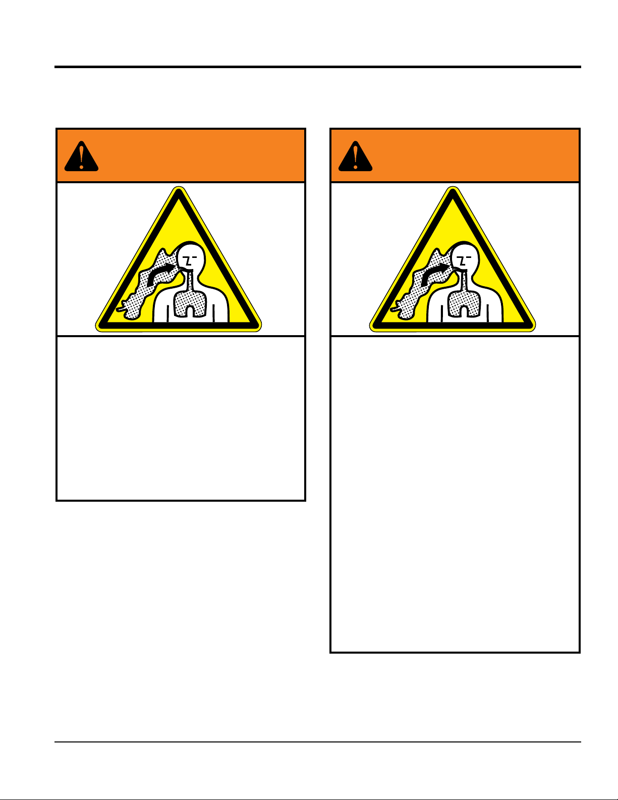
SILICOSIS/RESPIRATORY WARNINGS
WARNING
SILICOSIS WARNING RESPIRATORY HAZARDS
Grinding/cutting/drilling of masonry, concrete, metal and
other materials with silica in their composition may give
off dust or mists containing crystalline silica. Silica is a
basic component of sand, quartz, brick clay, granite and
numerous other minerals and rocks. Repeated and/or
substantial inhalation of airborne crystalline silica can
cause serious or fatal respiratory diseases, including
silicosis. In addition, California and some other
authorities have listed respirable crystalline silica as a
substance known to cause cancer. When cutting such
materials, always follow the respiratory precautions
mentioned above.
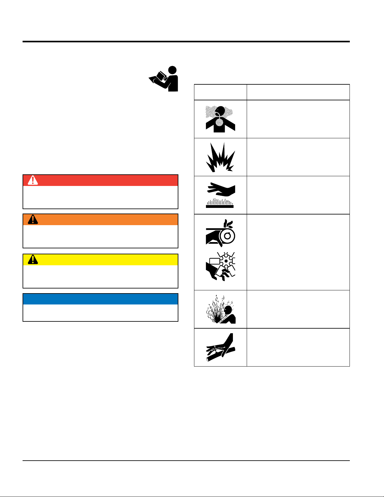
WARNING
Grinding/cutting/drilling of masonry, concrete, metal and
other materials can generate dust, mists and fumes
containing chemicals known to cause serious or fatal
injury or illness, such as respiratory disease, cancer,
birth defects or other reproductive harm. If you are
unfamiliar with the risks associated with the particular
process and/or material being cut or the composition of
the tool being used, review the material safety data
sheet and/or consult your employer, the material
manufacturer/supplier, governmental agencies such as
OSHA and NIOSH and other sources on hazardous
materials. California and some other authorities, for
instance, have published lists of substances known to
cause cancer, reproductive toxicity, or other harmful
effects.
Control dust, mist and fumes at the source where
possible. In this regard use good work practices and
follow the recommendations of the manufacturers or
suppliers, OSHA/NIOSH, and occupational and trade
associations. Water should be used for dust
suppression when wet cutting is feasible. When the
hazards from inhalation of dust, mists and fumes cannot
be eliminated, the operator and any bystanders should
always wear a respirator approved by NIOSH/MSHA for
the materials being used.
STXD6i RIDE-ON TROWEL • OPERATION MANUAL —REV. #0 (03/23/12) — PAGE 3
Page 4

STXD6i Ride-On Trowel
Proposition 65 Warning ........................................... 2
Silicosis/Respiratory Warnings ................................ 3
Table Of Contents .................................................... 4
Training Checklist .................................................... 6
Daily Pre-Operation Checklist ................................. 7
Safety Information ................................................8-3
Lifting And Transporting ......................................... 14
Specifications ........................................................ 15
Dimensions ............................................................ 16
General Information ............................................... 17
Components ..................................................... 18-19
Basic Engine .......................................................... 20
Inspection ......................................................... 21-22
Setup ..................................................................... 23
Operation .......................................................... 24-29
Maintenance ..................................................... 30-35
Troubleshooting ................................................ 36-39
TABLE OF CONTENTS
NOTICE
Specifications are subject to change without notice.
PAGE 4 — STXD6i RIDE-ON TROWEL• OPERATION MANUAL — REV. #0 (03/23/12)
Page 5

NOTES
STXD6i RIDE-ON TROWEL • OPERATION MANUAL —REV. #0 (03/23/12) — PAGE 5
Page 6

TRAINING CHECKLIST
Training Checklist
No. Description OK? Date
1
2
3 Fuel system, refueling procedure
4 Operation of spray and lights
5
6
7 Emergency stop procedures
8
9 Maintaining a hover
10 Maneuvering
11 Pitching
12 Matching blade pitch. Twin-Pitch™
Read operation manual
completely
Machine layout, location of
components, checking of engine
and hydraulic oil levels
Operation of controls (machine
not running)
Safety controls, safety stop switch
operation
Startup of machine, pre-heat,
engine choke
13 Concrete fi nishing techniques
14 Shutdown of machine
15 Lifting of machine (lift loops)
16 Machine transport and storage
PAGE 6 — STXD6i RIDE-ON TROWEL• OPERATION MANUAL — REV. #0 (03/23/12)
Page 7

DAILY PRE-OPERATION CHECKLIST
Daily Pre-Operation Checklist
1 Engine oil level
2 Hydraulic oil level
3 Radiator coolant level
4 Condition of blades
5 Blade pitch operation
6 Safety stop switch operation
STXD6i RIDE-ON TROWEL • OPERATION MANUAL —REV. #0 (03/23/12) — PAGE 7
Page 8
SAFETY INFORMATION
Do not operate or service the equipment before reading
Potential hazards associated with the operation of this
the entire manual. Safety precautions should be followed
at all times when operating this equipment.
Failure to read and understand the safety
messages and operating instructions could
result in injury to yourself and others.
SAFETY MESSAGES
The four safety messages shown below will inform you
about potential hazards that could injure you or others. The
safety messages specifi cally address the level of exposure
to the operator and are preceded by one of four words:
DANGER, WARNING, CAUTION or NOTICE.
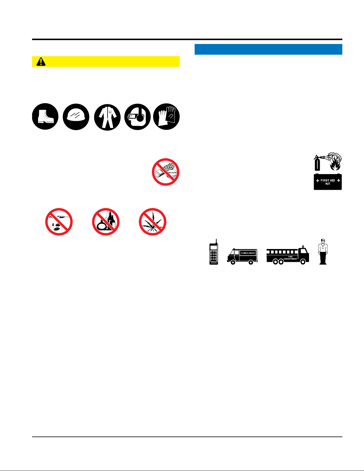
SAFETY SYMBOLS
DANGER
Indicates a hazardous situation which, if not avoided,
WILL result in DEATH or SERIOUS INJURY.
WARNING
Indicates a hazardous situation which, if not avoided,
COULD result in DEATH or SERIOUS INJURY.
CAUTION
equipment will be referenced with hazard symbols which
may appear throughout this manual in conjunction with
safety messages.
Symbol Safety Hazard
Lethal exhaust gas hazards
Explosive fuel hazards
Burn hazards
Rotating parts hazards
Indicates a hazardous situation which, if not avoided,
COULD result in MINOR or MODERATE INJURY.
NOTICE
Addresses practices not related to personal injury.
Pressurized fluid hazards
Hydraulic fluid hazards
PAGE 8 — STXD6i RIDE-ON TROWEL• OPERATION MANUAL — REV. #0 (03/23/12)
Page 9
GENERAL SAFETY
NOTICE
This equipment should only be operated by trained and
Whenever necessary, replace nameplate, operation and
accident due to equipment modifi cations. Unauthorized
recommended by Multiquip for this equipment. Damage
keep
Also, know the phone numbers
fi re department.
SAFETY INFORMATION
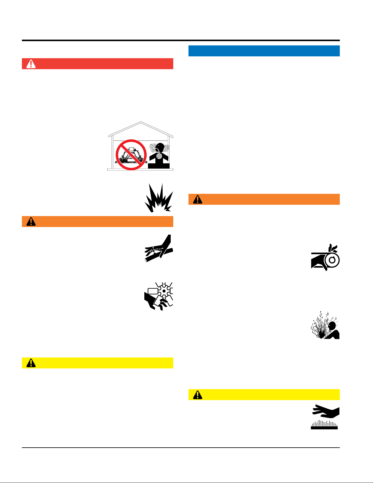
CAUTION
NEVER operate this equipment without proper protective
clothing, shatterproof glasses, respiratory protection,
hearing protection, steel-toed boots and other protective
devices required by the job or city and state regulations.
Avoid wearing jewelry or loose fi tting clothes that may
snag on the controls or moving parts as this can cause
serious injury.
NEVER operate this equipment when not
feeling well due to fatigue, illness or when
under medication.
NEVER operate this equipment under the
infl uence of drugs or alcohol.
ALWAYS clear the work area of any debris, tools, etc.
that would constitute a hazard while the equipment is
in operation.
qualifi ed personnel 18 years of age and older.
safety decals when they become diffi cult read.
Manufacturer does not assume responsibility for any
equipment modifi cation will void all warranties.
NEVER use accessories or attachments that are not
to the equipment and/or injury to user may result.
ALWAYS know the location of the nearest
fi re extinguisher.
ALWAYS know the location of the nearest
fi rst aid kit.
ALWAYS know the location of the nearest phone or
a phone on the job site.
of the nearest ambulance, doctor and
This information will be invaluable in the case of an
emergency.
No one other than the operator is to be in the working
area when the equipment is in operation.
DO NOT use the equipment for any purpose other than
its intended purposes or applications.
STXD6i RIDE-ON TROWEL • OPERATION MANUAL —REV. #0 (03/23/12) — PAGE 9
Page 10
TROWEL SAFETY
NOTICE
keep the machine in proper running condition.
store equipment properly when it is not being
used. Equipment should be stored in a clean, dry location
out of the reach of children and unauthorized personnel.
Association of Equipment Manufacturers (AEM) can be
engine is hot. High pressure boiling water will gush out
SAFETY INFORMATION
DANGER
Engine fuel exhaust gases contain poisonous carbon
monoxide. This gas is colorless and odorless, and can
cause death if inhaled.
The engine of this equipment requires an adequate free
fl ow of cooling air. NEVER operate this equipment in any
enclosed or narrow area
where free fl ow of the air is
restricted. If the air fl ow is
restricted it will cause injury
to people and property and
ser io us dama g e to t he
equipment or engine.
NEVER operate the equipment in an explosive
atmosphere or near combustible materials. An
explosion or fi re could result causing severe
bodily harm or even death.
WARNING
If applicable, NEVER use your hand to fi nd
hydraulic leaks. Use a piece of wood or
cardboard. Hydraulic fl uid injected into the
skin must be treated by a knowledgeable
physician immediately or severe injury or
death can occur.
DANGEROUS
GAS FUMES
ALWAYS
Fix damage to machine and replace any broken parts
immediately.
ALWAYS
A safety manual for opera ting and mainten ance
personnel of concrete power trowels produced by the
obtained for a fee by ordering through their website at
www.aem.org.
Order FORM PT-160
ENGINE SAFETY
WARNING
DO NOT place hands or fi n g e r s in s i d e en g i n e
compartment when engine is running.
NEVER operate the engine with heat shields or
guards removed.
Keep fi ngers, hands hair and clothing away
from all moving parts to prevent injury.
DO NOT remove the radiator cap while the
ALWAYS keep clear of rotating or moving
parts while operating the trowel.
NEVER disconnect an y emergency
or safety devices. These devices are
intended for operator safety. Disconnection of these
devices can cause severe injury, bodily harm or even
death. Disconnection of any of these devices will void
all warranties.
CAUTION
NEVER allow passengers or riders on the trowel during
operation.
NEVER lubricate components or attempt service on a
running machine.
NEVER place your feet or hands inside the guard rings
while starting or operating this equipment.
PAGE 10 — STXD6i RIDE-ON TROWEL• OPERATION MANUAL — REV. #0 (03/23/12)
of the radiator and severely scald any persons in the
general area of the trowel.
DO NOT remove the coolant drain plug
while the engine is hot. Hot coolant will
gush out of the coolant tank and severely
scald any persons in the general area of
the trowel.
DO NOT remove the engine oil drain plug while the
engine is hot. Hot oil will gush out of the oil tank and
severely scald any persons in the general area of the
trowel.
CAUTION
NEVER touch the hot exhaust manifold,
muffl er or cylinder. Allow these parts to cool
before servicing equipment.
Page 11
NOTICE
BATTERY SAFETY
drop the battery. There is a possibility that the
keep the battery charged. If the battery is not
charge battery if frozen. Battery can explode.
environment to avoid the risk of a dangerous concentration
NEGATIVE battery terminal
keep battery cables in good working condition.
SAFETY INFORMATION
NEVER run engine without an air fi lter or with a dirty air
fi lter. Severe engine damage may occur. Service air fi lter
frequently to prevent engine malfunction.
NEVER tamper with the factory settings
of the engine or engine governor. Damage
to the engine or equipment can result
if operating in speed ranges above the
maximum allowable.
FUEL SAFETY
DANGER
DO NOT start the engine near spilled fuel or combustible
fl uids. Fuel is extremely fl ammable and its vapors can
cause an explosion if ignited.
ALWAYS refuel in a well-ventilated area, away from
sparks and open fl ames.
ALWAYS use extreme caution when working with
fl ammable liquids.
DO NOT fi ll the fuel tank while the engine is running
or hot.
DANGER
DO NOT
battery will explode.
DO NOT expose the battery to open fl ames,
sparks, cigarettes, etc. The battery contains
combustible gases and liquids. If these
gases and liquids come into contact with a
fl ame or spark, an explosion could occur.
WARNING
ALWAYS wear sa fety glasses when
handling the battery to avoid eye irritation.
The battery contains acids that can cause
injury to the eyes and skin.
Use well-insulated gloves when picking up
the battery.
ALWAYS
charged, combustible gas will build up.
DO NOT
When frozen, warm the battery to at least 61°F (16°C).
DO NOT overfi ll tank, since spilled fuel could ignite if it
comes into contact with hot engine parts or sparks from
the ignition system.
Store fuel in appropriate containers, in well-ventilated
areas and away from sparks and fl ames.
NEVER use fuel as a cleaning agent.
DO NOT sm o ke around or near the
equipment. Fire or explosion could result
from fuel vapors or if fuel is spilled on a
hot engine.
ALWAYS recharge the battery in a well-ventilated
of combustible gases.
If the battery liquid (dilute sulfuric acid)
comes into contact with clothing or skin,
rinse skin or clothing immediately with
plenty of water.
If the battery liquid (dilute sulfuric acid) comes into
contact with eyes, rinse eyes immediately with plenty
of water and contact the nearest doctor or hospital to
seek medical attention.
CAUTION
ALWAYS disconnect the
before performing service on the equipment.
ALWAYS
Repair or replace all worn cables.
STXD6i RIDE-ON TROWEL • OPERATION MANUAL —REV. #0 (03/23/12) — PAGE 11
Page 12

TRANSPORTING SAFETY
TOWING SAFETY
make
Make sure the hitch and coupling of the towing vehicle
NEVER
tow a trailer with defective hitches, couplings, chains, etc.
Manufacturer recommends that trailer tires be
Also check the tire tread wear
safety
attach trailer’s safety chains to towing
make sure the vehicle and trailer directional,
The maximum speed for highway towing is 55 MPH unless
posted otherwise. Recommended off-road towing is not to
Avoid sudden stops and starts. This can cause skidding,
SAFETY INFORMATION
CAUTION
NEVER allow any person or animal to
stand underneath the equipment while
lifting.
Ride-on trowels are very heavy and
awkward to move around. Use proper
heavy lifting procedures and DO NOT
attempt to lift the trowel by the guard rings.
NEVER lift trowel with the operator on the machine.
NOTICE
The easiest way to lift the trowel is to utilize the lift loops
that are welded to the frame. These lift loops are located
to the left and right sides of the operator’s seat.
A strap/chain can be attached to these lift loops, allowing
a forklift or crane to lift the trowel up onto and off of a slab
of concrete. The strap or chain should have a minimum
of 2,000 pounds (1,000 kg) lifting capacity and the lifting
gear must be capable of lifting at least this amount.
NEVER transport trowel with fl oat pans attached unless
safety catches are used and are specifi cally cleared for
such transport by the manufacturer.
NEVER hoist the trowel more than three feet off the
ground with fl oat pans attached.
Before lifting, make sure that the lift loops are not
damaged.
Always make sure crane or lifting device has been
properly secured to the lift loops of the equipment.
ALWAYS shutdown engine before transporting.
NEVER lift the equipment while the engine is running.
Tighten fuel tank cap securely and close fuel cock to
prevent fuel from spilling.
Use adequate lifting cable (wire or rope) of suffi cient
strength.
CAUTION
Check with your local county or state safety
towing regulations, in addition to meeting
Department of Transpor tation (DOT)
Safety Towing Regulations, before towing
your trowel.
In order to reduce the possibility of an accident while
transporting the trowel on public roads, ALWAYS
sure the trailer that supports the trowel and the towing
vehicle are mechanically sound and in good operating
condition.
ALWAYS shutdown engine before transporting
are rated equal to, or greater than the trailer “gross
vehicle weight rating.”
ALWAYS inspect the hitch and coupling for wear.
Check the tire air pressure on both towing vehicle and
trailer.
infl ated to 50 psi cold.
on both vehicles.
ALWAYS make sure the trailer is equipped with a
chain.
ALWAYS properly
vehicle.
ALWAYS
backup, brake and trailer lights are connected and
working properly.
DOT Requirements include the following:
• Connect and test electric brake operation.
• Secure portable power cables in cable tray with tie
wraps.
DO NOT lift machine to unnecessary heights.
ALWAYS tie down equipment during transpor t by
securing the equipment with straps. Inspect straps to
make sure they are not frayed or damaged.
PAGE 12 — STXD6i RIDE-ON TROWEL• OPERATION MANUAL — REV. #0 (03/23/12)
exceed 15 MPH or less depending on type of terrain.
or jack-knifi ng. Smooth, gradual starts and stops will
improve towing.
Page 13

Avoid sharp turns to prevent rolling.
of recycling metal. Using a metal recycling center
This engine has been certifi ed to meet US EPA Evaporative
emission system by unauthorized personnel without proper
training could damage the equipment or create an unsafe
Additionally, modifying the fuel system may adversely affect
evaporative emissions, resulting in fi nes or other penalties.
The emission control label is an integral part of the emission
If a replacement emission label is needed, please contact
SAFETY INFORMATION
Trailer should be adjusted to a level position at all times
when towing.
Raise and lock trailer wheel stand in up position when
towing.
Place chock blocks underneath wheel to prevent rolling
while parked.
Place support blocks underneath the trailer’s bumper to
prevent tipping while parked.
Use the trailer’s swivel jack to adjust the trailer height to
a level position while parked.
ENVIRONMENTAL SAFETY/DECOMMISSIONING
NOTICE
Decommissioning is a controlled process used to safely
retire a piece of equipment that is no longer serviceable.
If the equipment poses an unacceptable and unrepairable
safety risk due to wear or damage or is no longer cost
effective to maintain (beyond life-cycle reliability) and is to
be decommissioned (demolition and dismantlement),be
sure to follow rules below.
DO NOT pour waste or oil directly onto the ground, down
a drain or into any water source.
Contact your country's Depar tment of
Public Works or recycling agency in your
area and arrange for proper disposal of
any electrical components, waste or oil
associated with this equipment.
promotes energy cost savings.
EMISSIONS INFORMATION
NOTICE
The diesel engine used in this equipment has been
designed to reduce harmful levels of carbon monoxide
(CO), hydrocarbons (HC) and nitrogen oxides (NOx)
contained in diesel exhaust emissions.
emissions requirements in the installed confi guration.
Attempting to modify or make adjustments to the engine
condition.
Emission Control Label
system and is strictly controlled by regulations.
The label must remain with the engine for its entire life.
your authorized Yanmar Engine Distributor.
When the life cycle of this equipment is over, remove
batter y and bring to appropr iate facility for lead
reclamation. Use safety precautions when handling
batteries that contain sulfuric acid.
When the life cycle of this equipment is over, it is
recommended that the trowel frame and all other metal
parts be sent to a recycling center.
Metal recycling involves the collection of metal from
discarded products and its transformation into raw
materials to use in manufacturing a new product.
Recyclers and manufacturers alike promote the process
STXD6i RIDE-ON TROWEL • OPERATION MANUAL —REV. #0 (03/23/12) — PAGE 13
Page 14

LIFTING AND TRANSPORTING
LIFTING THE TROWEL
When lifting trowel for moving or transporting, do the
following (see Figure 1).
TRANSPORTING THE TROWEL
After trowel has been lifted onto a flatbed truck, do the
following:
3. Attach suitable tie-down straps to the trowel. Route
tie-down straps on both sides as shown in Figure 2.
Figure 1. Lifting the Trowel
1. Secure two lifting straps to the lift loops located on the
left and right side of the trowel.
2. To lift, insert forklift forks through loops at the end of
lifting straps.
NOTICE
Ensure forklift has adequate lifting capacity for lifting
the trowel.
LEFT
Figure 2. Routing Tie-down Straps
4. Secure the trowel to the flatbed with the two straps,
making sure they are properly tied, to prevent
movement of the trowel during transport.
PAGE 14 — STXD6i RIDE-ON TROWEL• OPERATION MANUAL — REV. #0 (03/23/12)
Page 15

SPECIFICATIONS
Table 1. Trowel Specifications
Weight – lbs. (kgs.) Operating 2,165 (982)
Weight – lbs. (kgs.) Shipping (less pallet material) 2,077 (942)
Sound Pressure – dBA
Vibration – ft/s2 (m/s2)
2
3
Blade Tip Speed – ft/min (m/s) 1973 (10.0)
Fuel Tank – gallons (liters) 11 (42)
Rotor – RPM 0 to 130
Path Width – in. (cm) 117 (297)
TBD
TBD
Hydraulic Oil
MODEL Yanmar 4TNV84T-Z-DSA2
Type
No. of Cylinders 4
Bore X Stroke
Displacement 121.74 cu-in. (1.995 L)
Max Output 55 HP (41 kW) @3000 RPM
Cooling System Liquid cooled (Radiator)
Lube Oil Capacity 7.08 US qt. (6.7 liter) dipstick upper limit
P.T.O Position Flywheel End
4
(10W-40 hot weather)
(10W-30 cold weather)
Table 2. Engine Specifications
Vertical 4-cycle water cooled diesel engine - direct
injected - turbocharged
3.31 in. x 3.54 in.
(84 mm x 90 mm)
AW MV ISO68
Starting Method Electric Starting
Recommended Battery Capacity 12V-64 Ah (5h rating)
Engine Coolant Capacity 2.9 quarts (2.7 liters)
Charging System Alternator
Dimension (L x W x H)
25.55 x 19.65 x 28.08 in.
(649 x 499 x 713 mm)
Net Weight (Dry) 374.79 lbs (170 Kg.)
STXD6i RIDE-ON TROWEL • OPERATION MANUAL —REV. #0 (03/23/12) — PAGE 15
Page 16

B
DIMENSIONS
C
A
Figure 3. STXD6i Dimensions
Table 3. Trowel Dimensions
A – Length – in. (cm) 125 (318)
B – Width – in. (cm) 65 (165)
C – Height – in. (cm)
NOTES:
1. This value includes the seat height (Table 3).
2. Sound pressure is a weighted measure. Measured at the operators ear position while the ride-on trowel is operating
at full throttle on concrete in a manner most often experienced in “normal” circumstances. Sound pressure may vary
depending upon the condition of the concrete. Hearing protection is always recommended (Table 1).
3. The vibration level indicated is the maximum RMS (Root Mean Square) value obtained at the handle grip while
operating the ride-on trowel on curing concrete in a manner most often experienced in “normal” circumstances.
Values were obtained from all three axes of motion. The values shown represent the maximum RMS value from these
measurements (Table 1).
4. “AW” stands for anti-wear and “MV” stands for multi-viscosity. The 68 refers to the general viscosity range and is
similar to 10W-30-motor oil. It is recommended that AW MV 68 hydraulic oil be used. If this type of hydraulic oil is
not available then use 10W-30 engine oil for cold weather or 10W-40 engine oil for hot weather (Table 1).
1
56 (142)
PAGE 16 — STXD6i RIDE-ON TROWEL• OPERATION MANUAL — REV. #0 (03/23/12)
Page 17

GENERAL INFORMATION
INTENDED USE
Operate the STXD6i ride-on trowel, tools, and components
in accordance with the manufacturer's instructions. Use of
any other tools for stated operation is considered contrary
to designated use. The risk of such use lies entirely with the
user. The manufacturer cannot be held liable for damages
as a result of misuse.
FAMILIARIZATION
The STXD6i Ride-On Power Trowel is designed for the
floating and finishing of concrete slabs.
Take a walk around your trowel. Take notice of all the
major components like the engine, blades, air cleaner,
fuel system, fuel shut-off valve, ignition switch etc. Check
that there is always a proper level of oil in the engine and
a proper level of hydraulic oil in the hydraulic oil reservoir.
Read all the safety information carefully. Safety instructions
will be found throughout this manual and on the machine.
Keep all safety information in good, readable condition.
Operators should be well trained on the operation and
maintenance of the trowel.
HYDRAULIC STEERING
Dual palm grip joystick controls located to the left and
right of the operator are provided for steering the STXD6i
Ride-On Trowel. The joysticks are linked to three hydraulic
steering cylinders located within the frame of the machine.
HYDRAULIC PUMP
The hydraulic pump delivers controlled flow of hydraulic
fluid to the hydraulic motors.
Before using your trowel, test it on a flat, watered down
section of finished concrete. This trial test run will increase
your confidence in using the trowel and at the same time it
will familiarize you with the trowel’s controls and indicators.
In addition you will understand how the trowel will handle
under actual conditions.
ENGINE
This trowel is equipped with a Yanmar 4TNV84T diesel
engine. Refer to the engine owner’s manual for specific
instructions regarding engine operation.
BLADES
The blades of the trowel finish the concrete as they are
swirled around the surface. Blades are classified as
combination (10 or 8 inches wide) and finish (6 inches
wide). This trowel is equipped with six blades per rotor
equally spaced in a radial pattern and attached to a vertical
rotating shaft by means of a spider assembly.
Independent hydrostatic drive motors are coupled to the
engine-powered hydrostatic pump. Each motor drives a
spider assembly.
STXD6i RIDE-ON TROWEL • OPERATION MANUAL —REV. #0 (03/23/12) — PAGE 17
Page 18

2
3
4
7
5
8
1
14
13
10
9
18
6
Figure 4. Components (Front)
1. Seat — Place for operator to sit. Trowel blades will not
rotate unless operator is seated. Seat is adjustable.
COMPONENTS
16
15
28
12
27
11
26
25
24
23
22
7. Cruise Control Switch — Press this switch to engage
the cruise control. Press again to disengage.
17
20
19
21
2. Stop Lamp (Red) — Used to relay trouble codes
information that is severe enough to warrant stopping
the trowel.
3. Warning Lamp (Amber) — Used to relay trouble code
information that is reporting a problem with the system
but the trowel need not be immediately stopped.
4. Indicators:
Oil Indicator Light — Not connected on this machine.
Water Temperature Light — Lights red when water
temperature is high.
Charge Indicator — Lights red when electrical system
is not charging properly.
Aux 1 — Cold start lamp, indicates when cold start
sequence is enabled.
Aux 2 — Filter Condition lamp Indicates when hydraulic
filter needs serviced
Cold Start Aid — Indicates when engine cold start aid
is enabled.
8. Pitch Block — (Behind grill guard) Measure at the
service port and adjust pitch pressure at the pitch block.
9. Ignition Switch — With key inserted, turn switch
clockwise to start engine.
10. Foot Pedal — Controls blade speed. Slow blade
speed is accomplished by slightly depressing the foot
pedal. Maximum blade speed is accomplished by fully
depressing the foot pedal.
11. Removable Steps (left and right) — Provides for
safe footing for mounting and dismounting trowel.
When removed, provides access to spider and blade
assemblies.
12. Lights — Six low voltage halogen lights are provided
with this unit.
13. Grab Handles — Use to assist safe mounting and
dismounting trowel.
14. Lift Loops — Located on both the left and right sides
of the main frame. Used when the trowel must be lifted
onto a concrete slab.
5. Throttle Switch — Controls the speed of the engine.
Press up to increase engine speed (high). down to
decrease engine speed (low).
6. Fuel/Water Separator — Separates water, dirt and
sludge from fuel preventing engine component wear.
PAGE 18 — STXD6i RIDE-ON TROWEL• OPERATION MANUAL — REV. #0 (03/23/12)
15. Hour Meter — Indicates number of hours machine
has been used.
16. Retardant Spray Control Buttons (left and right) —
When pressed allows retardant spray to flow through
the spray nozzle located at the front of the machine.
Page 19

COMPONENTS
29
38
31
37
Figure 5. Components (Rear)
36 3334
17. Pitch Mode Switch — Sets the mode of operation of
the blade pitch system to either auto or manual.
18. Fuel Pump— Provides fuel flow to injection pump.
19. Blade Pitch Control (Twin Pitch) — Adjusts the pitch
on both rotors simultaneously but non-synchronously.
20. Blade Pitch Control Switch (left side) — Adjusts the
left side blade pitch independently of the right side.
39
35
30
31
32
30. Steering Control (right side) — Allows the unit to
move in either a forward, reverse left or right direction.
31. Grill Guards (left and right) — Protects operator from
moving components. Remove for maintenance access.
32. Documentation Canister — Storage for documentation
and other information regarding the trowel.
33. Battery — Provides +12V DC to the electrical system.
21. Hydraulic Reservoir — Part of frame. Holds hydraulic
oil necessary for pump operation.
22. Spray Nozzles — Spray nozzle for retardant. Two spray
nozzles are supplied with this unit.
23. Overflow Bottle — (Behind grill guard.) Supplies water
or coolant to the radiator when radiator water or coolant
level is low. Fill to indicated level as shown on bottle.
24. Fuel Gauge/Filler Cap — Indicates the amount of fuel
in the fuel tank. Remove this cap to add fuel.
25. Toolbox Compartment — Storage for tools.
26. Fuse Box — Contains fuses for control electronics.
27. Relays — Relays for lights and safety bypass switch.
28. Light Switch — When activated, turns on six halogen
lights. Lights offer better visibility when working indoors
29. Steering Control (left side) — Allows the unit to move
in a forward or reverse direction only.
34. Hydraulic Oil Filler Cap — Remove this cap to add
hydraulic oil. Open ONLY when system is cooled down
and all expanded oil has returned to the reservoir.
35. Hydraulic Oil Sight Glass — Indicates the level of the
hydraulic oil in the reservoir.
36. Hydraulic Suction Filter — Filters hydraulic fluid prior
to entering the system. (10 Micron absolute synthetic media.)
37. Retardant Spray Tank — Holds 5 gallons of retardant,
water, or other liquid.
38. Hydraulic Oil Expansion Tank — Accommodates
expanding hydraulic oil as it gets hot. The oil gravity
flows back to the reservoir as it cools down, therefore
NEVER open the Hydraulic Oil Filler Cap when the
system is warm and the oil has expanded.
39. Safety Bypass Switch — The trowel will not move
unless an operator is sitting on the seat. The weight
of an operator activates the switch allowing the rotors
to turn.
STXD6i RIDE-ON TROWEL • OPERATION MANUAL —REV. #0 (03/23/12) — PAGE 19
Page 20

BASIC ENGINE
1
2
15
14
3
4
12
11
10
9
8
5
6
Figure 6. Basic Engine
1. Air Filter — Helps provide clean source of air flow to
turbocharger and engine.
2. Muffler — Exhaust gases routed through here.
16
7
21
16
20
17
18
19
13
12. Oil Dip Stick — Remove to check amount and
condition of oil in crankcase.
13. ECO Governor — Controls engine rpm.
3. Fan belt — Driven by the engine crank during
operation, drives the water pump/fan as well as the
alternator.
4. Cooling Fan — Driven by the V-belt, the cooling fan
cools the engine by cooling water/antifreeze mixture
that circulates through the engine block and cylinder
head.
5. Crankshaft V-Pulley — Check fan V-belt between
V-Pulley and alternator to determine proper belt
tension.
6. Water Pump — Circulates coolant flow through engine.
7. Oil Filler Port — Remove to add fresh crankcase oil.
8. Oil Drain Plug — Remove plug to drain crankcase oil.
9. Injection Pump — Provides equal fuel flow to injectors.
10. Oil Filter — Spin-on type, filters oil for contaminants.
11. Oil Pressure Switch — Monitors oil level.
14. Flywheel — Main power is taken off from flywheel end.
15. Fuel Filter — Removes dirt and water from the fuel.
16. Lifting Eye — Two lifting eyes are provided if the
removal/installation of the engine becomes necessary.
17. Air Intake Port — Provides air from the air cleaner to
the turbocharger unit.
18. Turbocharger — Provides pressurized intake air to the
cylinder by means of a turbine energized by exhaust
gas that rotates the blower.
19. Starter — Starts engine when ignition key is rotated
to the "START" position.
20. Alternator — Provides current to the electrical
system and charges the battery. Driven by means of
a crankshaft/V-belt pulley system.
21. Fan Belt Tension Adjustment — This bolt provides
means to adjust the V-belt tension at the alternator
bracket.
PAGE 20 — STXD6i RIDE-ON TROWEL• OPERATION MANUAL — REV. #0 (03/23/12)
Page 21

INSPECTION
NOTICE
The following sections are intended to assist the
operator with inspection of the STXD6i Ride-On Trowel.
It is extremely important that these sections are read
carefully before attempting to use the trowel in the field.
DO NOT use your Ride-On Trowel until these sections
are thoroughly understood.
WARNING
Failure to understand the operation of the STXD6i
Ride-On Trowel could result in personal injury or severe
damage to the trowel.
ENGINE OIL
ENGINE OIL
FILLER CAP
HYDRAULIC OIL
1. Check the hydraulic oil condition through the sight glass
(Figure 8) Replace hydraulic oil if dirty or if bubbles
are present.
HYDRAULIC OIL
SIGHT GLASS
Figure 8. Hydraulic Oil Sight Glass
2. Determine if the hydraulic oil is low. The hydraulic tank
has an elevated overflow bottle. DO NOT remove the
fill cap when the oil is hot or spillage will occur.
DIPSTICK
FULL
ADD OIL
Figure 7. Engine Oil Check and Fill
F
L
ENGINE OIL
FILLER CAP
1. When checking or adding oil, place the machine so
the engine is level.
2. Pull the engine oil dipstick from its holder, (Figure 7).
3. Determine if engine oil is low. Oil should be between
the upper limit and lower limit (add oil) lines.
4. If oil is below the "Add Engine Oil" line add oil up
to upper limit on the dipstick. Allow enough time for
any added oil to make its way to the oil pan before
rechecking.
CAUTION
CAUTION
Hydraulic oil can get HOT! ALWAYS allow
hydraulic oil to cool before removing fill
cap.
CAUTION
Removal of the fill cap when oil fills the
sight glass will cause hydraulic oil to spill.
Clean up hydraulic oil spills immediately.
3. To add hydraulic oil, remove fill cap on the hydraulic
tank. Fill to overflow with hydraulic system cool. Use
Chevron AW / MV ISO 68 or equivalent.
DO NOT overfill the oil pan with engine oil. Always keep
the engine oil level between the upper and lower limit
lines on the dipstick.
STXD6i RIDE-ON TROWEL • OPERATION MANUAL —REV. #0 (03/23/12) — PAGE 21
Page 22

INSPECTION
FUEL
1. Determine if the engine fuel is low (Figure 9).
FUEL
E F
Figure 9. Fuel Gauge
2. If fuel level is low, remove the fuel filler cap and fill with
ASTM D975 No1D or No. 2D diesel fuel. Handle fuel
safely. Motor fuels are highly flammable and can be
dangerous if mishandled.
3. Below are additional technical fuel requirements:
The fuel cetane number should be equal to 45 or
higher.
The carbon residue content must not exceed
0.01% by volume. Less than 0.1% is preferred.
The total aromatics content should not exceed 35%
by volume. Less than 30% is preferred.
The PAH (polycyclic aromatic hydrocarbons )
content should be below 10% by volume.
The metal content of Na, Mg, Si, and Al should be
equal or lower than 1 mass ppm.
Lubricity: The wear mark of WS1.4 should be Max
0.018 in (µm) at HFRR test.
This trowel can use biodesel fuel. Refer to the
Yanmar Service manual for details.
CAUTION
DO NOT smoke while refueling. DO NOT
attempt to refuel the ride-on trowel if the
engine is hot or running.
The sulfur content must not exceed 0.5% by
volum e. Less tha n 0.05 % is preferred. For
electronically-controlled engines, it is mandatory
to use fuel that does not contain 0.1% or more
sulfur content.
In general, using a high sulfur fuel may possible
result in corrosion inside the cylinder. Low sulfur
(300-500 mg/kg sulfur content) or ultra low sulfur
fuel should be used.
Never mix kerosene, used engine oil, or residual
fuels with the diesel fuel.
The water and sediment in the fuel should not
exceed 0.05% by volume.
Keep the fuel tank and fuel-handling equipment
clean at all times.
Poor quality fuel can reduce engine performance
and/or cause engine damage.
Fuel additives are not recommended. Some fuel
additives may cause poor engine performance.
CAUTION
DO NOT store the Ride-On Trowel with fuel in the tank
for an extended period of time. Completely drain the
fuel system (tank, lines, etc.) if the unit is to be put into
long term storage. For shorter or intermediate periods
of time the tank should be filled to avoid condensation
that could cause contamination of the fuel.
The ash content must not exceed 0.01% by
volume.
PAGE 22 — STXD6i RIDE-ON TROWEL• OPERATION MANUAL — REV. #0 (03/23/12)
Page 23

SETUP
The purpose of this section is to assist the user in setting
up a new trowel. If your trowel is already assembled, (seat,
handles, knobs and battery), this section can be skipped.
NOTICE
The new trowel cannot be put into service until the
setup instructions are completed. These instructions
only need to be performed at the time of unpacking a
new trowel.
BATTERY SETUP
CAUTION
Use all safety precautions specified by the battery
manufacturer when working with the battery. See Safety
Information section of this manual for more details on
battery safety.
1. This trowel was shipped with a wet charged battery.
This battery may need to be charged for a brief period
of time as per manufacturer's instructions.
2. To install the battery on the trowel, make sure that the
battery is well seated in the battery box (Figure 10).
Figure 10. Battery Box
3. Connect the positive cable to the positive terminal on
the battery first, then connect the negative cable to the
negative terminal.
4. Close the plastic battery box cover and secure the
battery box.
STXD6i RIDE-ON TROWEL • OPERATION MANUAL —REV. #0 (03/23/12) — PAGE 23
Page 24

OPERATION
ACC
STARTING THE ENGINE
WARNING
NEVER operate the trowel in a confined
area or enclosed area structure that does
not provide ample free flow of air.
CAUTION
ALWAYS wear approved eye and hearing
protection before operating the ride-on
power trowel.
CAUTION
NEVER place hands or feet inside the guard rings while
the engine is running. ALWAYS shut the engine down
before performing any kind of maintenance service on
the trowel.
1. With one foot on the ground and the other foot placed
on the trowel’s platform, grasp the grab handles lifting
yourself onto the trowel. Then sit down in the operator’s
seat.
NOTICE
It is recommended that the operation of the Safety Stop
Switch is checked prior to performing any troweling
operations. Doing this will verify that the switch is
working properly contributing to safe operation of the
machine.
3. Insert the ignition key into the ignition switch (Figure 11).
(Unused)
OFF
ON
PREHEAT
(Unused)
START
Figure 11. Ignition Switch and Key
4. Turn the ignition key clockwise to the ON position. Aux
1, Aux 2, Coolant Temp, Cruise, Pitch Mode Lights will
light for 10 seconds (Figure 12) and Charge Lamp will
remain lit until engine starts. Coolant fan will run for
10 seconds.
NOTICE
DO NOT grab hold of the joysticks to lift yourself onto
the trowel. Pulling on the joysticks repeatedly will
weaken the units. ALWAYS use the grab handles to
lift yourself on the trowel.
2. This trowel is equipped with a Safety Bypass Switch.
The trowel will not move unless an operator is sitting in
the seat. While the engine can be started or continue
to run with the operator off the seat, the rotors will not
rotate. The weight of an operator activates a switch
within the seat allowing the rotors to turn.
WARNING
NEVER disable or disconnect the Safety Bypass
Switch. It is provided for the operator's safety. Injury
may result if it is disabled, disconnected or improperly
maintained.
Figure 12. Indicator Lights
5. When the Aux1 light turns off, turn ignition key fully
clockwise to the START position and listen for engine
to start. Once engine has started release ignition key.
The throttle speed defaults to idle. Let the engine warm
for a few minutes.
NOTICE
The throttle will default to full speed when the foot pedal
is depressed and operator presence is detected.
6. Repeat this section a few times to get fully acquainted
with the engine starting procedure.
PAGE 24 — STXD6i RIDE-ON TROWEL• OPERATION MANUAL — REV. #0 (03/23/12)
Page 25

OPERATION
ENGINE THROTTLE
The engine throttle has three primary speed settings: Idle,
Charge, and Operating RPM.
1. Each press of the Throttle Switch (Figure 13) steps it
from idle to operating speed if operator presence is
detected.
THROTTLE
SWITCH
CRUISE CONTROL
SWITCH
Figure 13. Throttle Switch
2. The speed defaults to idle at startup or when no
operator presence is detected.
3. The speed defaults to full speed when the foot pedal is
depressed and operator presence is detected.
2. Engine speed changes to idle when operator leaves
the seat or the foot pedal is released for more than a
set period of time.
PUMP STROKE
Stroke is proportionally controlled by the foot pedal input
position via feedback from the stroke position sensor.
Safety Interlock
1. Pump is automatically de-stroked if operator presence
not detected.
2. Upon startup, the foot pedal will not control pump
stroke if the pedal is depressed unless it has been
released after start up. This prevents machine from
unintentionally moving when started.
3. Pump is automatically de-stroked if error is detected
from foot pedal sensor.
4. Stroke position is directly controlled by foot pedal if
error is detected from the stroke sensor.
CRUISE CONTROL
Battery Management
Idle speed is raised automatically to prevent battery drain
when:
Hydraulic oil cooler fan is running.
Lights are on
Battery voltage drops below preset voltage
Cold Start
1. Idle speed is raised automatically to expedite bringing
machine to operating temperature when:
Hydraulic oil is below preset temperature (Oil
forces across relief valve to raise oil temperature).
Engine coolant temperature is below preset
temperature.
2. Aux 1 on indicator will light when machine is in cold
start mode.
Safety Interlocks
1. Full engine throttle is allowed only when operator
presence detected.
Setting the Cruise Control will set and maintain a set pump
stroke position command.
1. Press the cruise control switch (Figure 14) to engage
the cruise control. The cruise control switch LED
indicator lights when cruise control is engaged.
THROTTLE
SWITCH
CRUISE CONTROL
SWITCH
Figure 14. Cruise Control Switch
2. Press the cruise control switch again to disengage the
cruise control. The cruise control switch LED indicator
will turn off when cruise control is disengaged.
3. The cruise control can also be disengaged by
STXD6i RIDE-ON TROWEL • OPERATION MANUAL —REV. #0 (03/23/12) — PAGE 25
Page 26

OPERATION
HANDLE
the operator resuming control of pump stroke by
depressing the foot pedal after releasing.
Safety Interlocks
1. Error is detected in either Pedal Position Sensor, or
Stroke Position Sensor.
2. Operator Presence is not detected.
3. Error Code is received from engine.
POWER MANAGEMENT
1. Pump stroke command is scaled when engine load
reaches a threshold capacity, maintaining maximum
rotor speed and preventing engine from stalling.
2. The pedal will not be able to stroke the pump until the
engine is at full RPM.
HYDRAULIC OIL COOLER FAN CONTROL
The hydraulic oil cooler fan is controlled based on oil
temperature. Fan turns on and off at preset temperatures.
STEERING
Two joysticks (Figure 15 and Figure 16) located to the left
and right of the operator’s seat provide directional control for
the STXD6i Ride-On Trowel. Table 3 illustrates the various
directional positions of the joysticks and their effect on the
ride-on trowel.
NOTICE
All directional references with respect to the joysticks
are from the operator’s seat position.
FORWARD
PALM
REVERSE
HYDRAULIC OIL FILTER MONITORING
Operator is alerted via Aux 2 on Engine\Machine monitor
if filter needs service when filter switch is activated and oil
is at operating temperature.
FAULT ALERTING
Red Stop Lamp
This lamp is used to relay trouble code information that
is severe enough to warrant stopping the trowel. This is
enabled via a command from engine J1939 fault code for
Red Stop Lamp or fault is detected from Foot Pedal sensor.
Amber Warning Lamp
This lamp is used to relay trouble code information that
is reporting a problem with the system but the trowel
need not be immediately stopped. This is enabled via a
command from engine J1939 fault code for Warning Lamp,
Malfunction indicator Lamp, Protect Lamp. Fault is detected
from all other machine sensors and MCU.
Figure 15. Left Joystick Control
FORWARD
LEFT
REVERSE
Figure 16. Right Joystick Control
See Table 4 for steering and directional relationship to
joystick control movement.
PALM
HANDLE
RIGHT
PAGE 26 — STXD6i RIDE-ON TROWEL• OPERATION MANUAL — REV. #0 (03/23/12)
Page 27

OPERATION
LEFT
LEFT
Table 4. Joystick Directional Positioning
CONTROL JOYSTICK
& DIRECTION
Move
LEFT Joystick
FORWARD
Move Joystick
LEFT
BACKWARD
Move Joystick
RIGHT
FORWARD
Move Joystick
RIGHT
BACWARD
Move Joysticks
BOTH
FORWARD
Move Joysticks
BOTH
BACKWARD
Move Joystick
RIGHT
to the RIGHT
Move Joystick
RIGHT
to the LEFT
Causes only the
right side of the
ride-on trowel to
move forward.
Causes only the
right side of the
ride-on trowel to
move backward.
RESULT
Causes the ride-on trowel
to move forward in
a straight line.
Causes the ride-on trowel
to move backard in
a straight line.
Causes the ride-on trowel
to move to the right.
Causes the ride-on trowel
to move to the left.
Causes only the
left side of the
ride-on trowel to
move forward.
Causes only the
left side of the
ride-on trowel to
move backward.
2. Push both the left and right joysticks forward (Figure 18).
JOYSTICK
CONTROL
Figure 18. Joystick Control Forward Direction
PUSH
FORWARD
RIGHT
JOYSTICK
CONTROL
3. With your right foot, slowly depress the foot pedal
halfway. Notice that the ride-on trowel begins to move
in a forward direction. Release both joystick controls
to stop forward movement then remove your right foot
from the foot pedal.
4. Practice holding the machine in one place as you
increase blade speed. When about 75% of maximum
blade speed has been reached, the blade will be
moving at proper finishing speed. The machine may be
difficult to keep in one place. Trying to keep the ride-on
trowel stationary is a good practice for operation.
5. Practice maneuvering the ride-on trowel using the
information listed in Table 4. Try to practice controlled
motions as if you were finishing a slab of concrete.
Practice edging and covering a large area.
1. The foot pedal (Figure 17) solely controls blade
speed. The position of the foot pedal determines
the blade speed. Slow blade speed is obtained by
slightly depressing the pedal. Maximum blade speed
is obtained by fully depressing the pedal.
Figure 17. Blade Speed Control Foot Pedal
STXD6i RIDE-ON TROWEL • OPERATION MANUAL —REV. #0 (03/23/12) — PAGE 27
6. Try adjusting the pitch of the blades. This can be done
with the ride-on trowel stopped or while the trowel is
moving. Test the operation of optional equipment like
retardant spray and lights.
7. Pull both the left and right joyst icks backward
(Figure 19) and repeat steps 3 through 6 while
substituting the word reverse for forward.
JOYSTICK
CONTROL
RIGHT
JOYSTICK
CONTROL
PULL
BACKWARDS
Figure 19. Joystick Control Reverse Direction
Page 28

OPERATION
BLADE PITCH CONTROL
There are two modes of operation of the blade pitch system
that can be set by the Pitch Mode Switch (Figure 20):
Smart Pitch™
Manual
The trowel blades can be pitched for various finishing
operations with the two rocker switches located on the left
control panel next to the left joystick control (Figure 20).
PITCH MODE
SWITCH
TWIN-PITCH
SWITCH
LEFT-PITCH
SWITCH
Figure 20. Blade Pitch Control
Smart Pitch™ Mode
When the Pitch Mode Switch is in the Smart Pitch™ position
(indicator light on), the twin-pitch and left-pitch switches
operate as follows:
the unsynchronized state
NOTICE
Moving the switches forward increases the pitch while
moving them backward decreases the pitch.
NOTICE
Momentarily depressing the Twin Pitch Switch will resynchronize the pitch.
MANUAL Mode (Pitch Mode Light is Off)
1. When the Twin Pitch Switch is pressed (up or down),
the pitch on both rotors will be changed simultaneously
but non-synchronously.
2. When the Left Pitch Switch is pressed the pitch on the
left rotor will be changed, while the pitch on the right
rotor remains constant.
NOTICE
IMPORTANT! To get blades absolutely flat for using
float pans, pitch them as follows:
Press and hold down both pitch switches until mode
light blinks before installing float pans.
1. When the Twin Pitch Switch (3-position, center off)
is pressed (up or down), the right and left hand rotor
pitch are changed and then the left hand rotor pitch is
synchronized to the right hand as follows:
a. The Twin Pitch Switch (up or down) causes the RH
Pitch (up or down) Coil and LH Pitch (up or down)
Coil and Pitch Dump Valve Coil to be actuated
changing the pitch of the blades.
b. When the operator achieves the desired pitch on
the right hand blades and releases the Twin Pitch
Switch, the LH Pitch (up or down) coil and Pitch
Dump Valve Coil are actuated until the calibrated
LH Pitch Position signal matches calibrated RH
Pitch Position signal (.010” by Default). During this
time the Pitch Mode Light will flash (.1 s on, .1 s off).
2. When the Left Pitch Switch (3-position, center off) is
pressed the pitch on the left rotor will be changed, while
the pitch on the right rotor remains constant. The Pitch
Mode Light will turn off, to indicate pitch function is in
PANNING Mode
When both the Twin Pitch Switch and Left Pitch Switch are
pressed in the down position and held for preset period (5s
by default), the machine will enter Panning Mode.
1. The RH Pitch DN Coil and LH Pitch DN Coil will be
activated pulling the yokes upward against Retracted
Cylinder Stop, deactivating the pitch system, and
allowing the blades to float for panning.
2. The Pitch Mode Light will flash (.9 s on .1 s off) when
in this mode.
3. Machine remains in this mode until either the Twin
Pitch Switch or Left Pitch Switch is activated in the
upward direction.
PAGE 28 — STXD6i RIDE-ON TROWEL• OPERATION MANUAL — REV. #0 (03/23/12)
Page 29

ENGINE SHUTDOWN
1. Return the throttle switch (Figure 21) to idle and allow
the engine to idle for 5 minutes.
THROTTLE
SWITCH
CRUISE CONTROL
SWITCH
Figure 21. Engine Shutdown
NOTICE
Failure to allow the engine to idle for 5 minutes before
shutting engine OFF may lead to turbocharger damage.
OPERATION
2. Turn the ignition key counterclockwise to the OFF
position then remove the key.
3. Clean and remove any foreign debris from the trowel.
STXD6i RIDE-ON TROWEL • OPERATION MANUAL —REV. #0 (03/23/12) — PAGE 29
Page 30

Table 5. Maintenance Schedule
System Check Item DAILY
Check Air Cleaner X
Clean Air Cleaner Element X
Replace Air Cleaner Element X
Check and Refill Engine Coolant X
Check and Clean Radiator Fins X
Check and Adjust Cooling Fan V-Belt
Drain, Flush, and Refill Cooling System
With New Coolant
Engine
Trowel
Check Engine Oil Level X
Drain and Fill Engine Oil
Replace Engine Oil Filter
Check and Refill Fuel Tank Level X
Drain Fuel Tank X
Drain Fuel Filter/Water Separator X
Check Fuel Filter/Water Separator X
Clean Fuel Filter/Water Separator X
Replace Fuel Filter X
Change Hydraulic Oil and Filter
Relube Arms, Thrust Collar, and Clutch X
Remove, Clean, Reinstall, and Relube
Arms, and Thrust Collar
Check and replace if necessary, arm
bushings and thrust collar bushings.
Check blades for excessive wear or
damage and replace as necessary.
Adjust Blade Speed
X
Every
50 Hrs
X
1st time
X
1st time
X
1st time
Every
100 Hrs
X
1st time
X
MAINTENANCE
Periodic Maintenance Interval
Every
250 Hrs
X
2nd time
and
after
X
2nd time
and
after
X
2nd time
and
after
X
2nd time
and
after
Every
500 Hrs
X
X (if
needed)
Every
1000
Hrs
X
or yearly
which-
ever
comes
first
Every
1500
Hrs
Every
2000
Hrs
PAGE 30 — STXD6i RIDE-ON TROWEL• OPERATION MANUAL — REV. #0 (03/23/12)
Page 31

MAINTENANCE
CAUTION
Cer ta in m a in t en an c e o p e ra t io n s o r m a ch i ne
adjustments require specialized knowledge and skill.
Attempting to perform maintenance operations or
adjustments without the proper knowledge, skills or
training could result in equipment damage or injury to
personnel. If in doubt, consult your dealer.
AIR CLEANER
This Yanmar engine is equipped with a replaceable, highdensity paper air cleaner element. Some will have an inner
element that is used as a backup filter should the outer
element becomes damaged.
See Figure 22 for air cleaner components.
ARROW
MARK
(CASE)
AIR CLEANER
CASE
MAIN
ELEMENT
ARROW
MARK
(DUST PAN)
DUST PAN
Air Cleaner Service
CAUTION
Wear prot ective equip ment suc h as
approved safety glasses or face shields
and dust masks or respirators when
cleaning air filters with compressed air.
To service the air cleaner perform the following steps. See
Figure 22 for location of parts.
4. Release the latches located on either side of the air
cleaner dust pan. Remove the dust pan.
5. Remove the air cleaner element.
6. Blow low pressure air from the inside of the element
to dislodge the dust and dirt. Do not use excessive air
pressure or the element will be damaged and will need
to be replaced.
7. Replace the element if it is damaged or excessively
dirty.
8. Clean the inside of the dust pan.
9. Reinstall the element or if equipped, the precleaner
over the paper air cleaner element.
10. Reinstall the air cleaner dust pan and secure the
latches.
LATCH
EVACUATOR
VALVE
Figure 22. Air Cleaner Components
1. Check the air cleaner daily or before starting the engine.
2. Check for and correct heavy buildup of dirt and debris
along with loose or damaged components.
3. Replace the element if it is found to be damaged,
excessively dirty, or oily.
NOTICE
Operating the engine with loose or damaged air cleaner
components could allow unfiltered air into the engine
causing premature wear and failure.
STXD6i RIDE-ON TROWEL • OPERATION MANUAL —REV. #0 (03/23/12) — PAGE 31
NOTICE
DO NOT run the engine with the air cleaner removed
or without an element.
RADIATOR/COOLING SYSTEM
CAUTION
HOT coolant can cause severe burns. DO
NOT remove cap if radiator is HOT.
1. Check radiator for leaks that would indicate corrosion
or damage.
2. Check cooling water level daily. Top off as necessary.
Always use clean, soft water and add a long life
coolant antifreeze. Use the mixing ratios specified by
the Antifreeze manufacturer. Replace cooling water at
least once a year.
Page 32

MAINTENANCE
3. Check radiator hoses for fatigue or cracking. Replace
if in doubt of the integrity of the hoses.
4. Check radiator cap seal and replace as necessary.
Refer to your engine manual for additional information.
RADIATOR CLEANING
1. Blow off dirt and dust from fins and radiator with 28 psi
(0.19 MPa) or less of compressed air (Figure 23). Be
careful not to damage the fins with the compressed air.
2. If there a large amount of contamination on the fins, use
detergent to clean and rinse thoroughly with tap water.
CAUTION
NEVER use high-pressure water or compressed air at
greater than 28 psi (193 kPa) or a wire brush to clean
the radiator fins. Radiator fins damage easily.
.
FAN BELT TENSION
A slack fan belt may contribute to overheating, or to
insufficient charging of the battery. Inspect the fan belt for
damage and wear and adjust it in accordance with the
Yanmar Engine Owner’s Manual.
The fan belt tension is proper if the fan belt bends 10 to 14
mm when depressed with the thumb as shown in Figure 24.
DEFLECTION
Figure 23. Radiator Cleaning
Figure 24. Fan Belt Tension
ENGINE OIL
1. When checking or adding oil, place the machine so
the engine is level.
2. Pull the engine oil dipstick from its holder.
3. Determine if engine oil is low. Oil should be between
the upper limit and lower limit (add oil) lines.
4. If oil is below the "Add Engine Oil" line add oil up
to upper limit on the dipstick. Allow enough time for
any added oil to make its way to the oil pan before
rechecking.
PAGE 32 — STXD6i RIDE-ON TROWEL• OPERATION MANUAL — REV. #0 (03/23/12)
Page 33

MAINTENANCE
Changing Engine Oil And Filter
Change the engine oil and filter after the first 50 hours of
use, then every 6 months or 250 hours. Refer to Table 6 for
recommended oil viscosity. Refer to Figure 25 for location
of parts.
Table 6. Recommended Viscosity Grades
10W
20W
SAE 10W-30
SAE 15W-40
# 30
-20
F
C
-30
TEMPERATURE RANGE EXPECTED BEFORE NEXT OIL CHANGE
-20
0
-10
32 40 60 80 100
20
10
0
20 30 40
5. Clean sealing surface on engine where filter mounts.
6. Coat the seal of the new oil filter with clean engine oil.
Install new filter first by hand until it contacts the engine
sealing surface. Tighten it another 3/4 turn using the
filter wrench.
7. Fill engine with oil until it shows between the upper and
lower limits on the dipstick. Do Not overfill.
8. Run the engine briefly for several minutes. Watch for
oil leakage. Shut the engine down and allow it to sit
for several minutes. Top off the oil to the upper limit on
the dipstick.
FUEL FILTER
1. Replace the engine fuel filter element (Figure 26) every
500 hours.
OIL FILLER
CAP
DIP STICK
OIL FILTER
OIL DRAIN
PLUG
Figure 25. Engine Oil Service Components
1. Remove the oil filler cap while draining the oil to allow
the engine to drain easily.
2. Remove the drain plug to drain the oil.
3. After oil is sufficiently drained, securely tighten the
drain plug.
FUEL FILTER
Figure 26. Fuel Filter
4. Using a filter wrench, turn the oil filter counterclockwise
to remove.
STXD6i RIDE-ON TROWEL • OPERATION MANUAL —REV. #0 (03/23/12) — PAGE 33
Page 34

MAINTENANCE
Refer to your engine manual for specific details to perform
this operation.
FUEL/WATER SEPARATOR
Inspect the Fuel/Water Separator daily. If the Fuel/Water
Separator (Figure 27) has collected a significant amount of
water and sediment at the bottom of the cup, it should be
drained off. Refer to your engine manual for specific details
to perform this operation.
FUEL
COCK
RETAINING
RING
SEDIMENT
CUP
ENGINE TUNE-UP
At the front of this manual is a “Daily Pre-Operation
Checklist”. Make copies of this checklist and use it on a
daily basis.
NOTICE
See the engine manual supplied with your machine
for appropriate engine maintenance schedule and
troubleshooting guide for problems.
ALWAYS disconnect battery cables before attempting any
service or maintenance on the ride-on trowel.
HYDRAULIC OIL FILTER
1. Change the hydraulic oil and filter (Figure 28) after the
first 100 hours of use then change every 250 hours.
Use 10 micron absolute synthetic media filter.
Figure 27. Fuel/ Water Separator
OIL AND FUEL LINES
1. Check the oil and fuel lines and connections regularly
for leaks or damage. Repair or replace as necessary.
2. Replace the oil and fuel lines every two years to
maintain the line's performance and flexibility.
CAUTION
NEVER place hands near the belts or fan
while the trowel is running.
HYDRAULIC
OIL FILTER
Figure 28. Hydraulic Oil Filter
BATTERY/CHARGING SYSTEM
1. Check and clean battery terminals for corrosion.
2. Never attempt to charge a battery that is frozen. The
battery can explode unless first allowed to thaw.
3. Disconnect the negative terminal ( - ) of the battery
during storage. If unit will be stored where ambient
temperature will drop to -15
store battery in a warm, dry place.
4. Check manufacturer's recommendations for maintaining
and charging battery.
o
C or less, remove and
PAGE 34 — STXD6i RIDE-ON TROWEL• OPERATION MANUAL — REV. #0 (03/23/12)
Page 35

MAINTENANCE
LONG TERM STORAGE
1. Remove the battery.
2. Drain fuel from fuel tank.
3. Clean exterior with a cloth soaked in clean oil.
4. Store unit covered with plastic sheet in a moisture and
dust-free location out of direct sunlight.
CAUTION
NEVER store the ride-on trowel with fuel in the tank for
any extended period of time. Always clean up spilled
fuel immediately.
INSTALLING PANS ONTO FINISHER BLADES
These round discs, sometimes referred to as "pans", attach
to the spiders arms and allow early floating on wet concrete
and easy movement from wet to dry areas. They are also
very effective in embedding large aggregates and surface
hardeners.
3. Attach the blade tie-downs to the far side of the Z-Clip
brackets with tie-down knobs as shown in Figure 29.
4. Check to make certain that the blade edges are
secured under the Z-Clips and the tie-downs are
secured completely over the edges of the blade bar
before the machine is put back into operation.
Refer to Figure 29 when installing pans onto finisher blades.
KNOB, TIE-DOWN
Z-CLIP PANS
Z-CLIP, PAN
Figure 29. Z-Clip Finisher Pan Installation
TIE-DOWN, BLADE
BLADE ASSEMBLY
1. Lift trowel just enough to slide pan under blades. Lower
finisher onto pan with blades adjacent to Z-Clips.
2. Rotate blades into position under Z-Clips. Ensure that
the blades are rotated in the direction of travel when
the machine is in operation or use the engine to rotate
the blades into position.
STXD6i RIDE-ON TROWEL • OPERATION MANUAL —REV. #0 (03/23/12) — PAGE 35
Page 36

Symptom Possible Problem Solution
Safety stop switch not functioning.
If trowel “bounces, rolls concrete, or makes uneven
swirls in concrete”..
Machine has a perceptible rolling motion while
running.
TROUBLESHOOTING
Troubleshooting (Ride-On Hydraulic Trowel)
Other problems? Consult engine manufacturer’s manual.
Loose wire connections? Check wiring. Replace as necessary.
Bad contacts? Replace seat cushion (contains the switch).
Make certain blades are in good condition, not
excessively worn. Finish blades should measure no
Blades?
Spider?
Bent trowel arms?
Trowel arm bushings?
Thrust collar?
Thrust collar bushing?
Thrust bearing worn?
Blade pitch?
Spider Finger Screws? Adjust per procedure in Maintenance Section.
Yoke?
less than 2"" (50mm) from the blade bar to the trailing
edge, combo blades should measure no less that 3.5""
(89mm). Trailing edge of blade should be straight and
parallel to the blade bar.
Check that all blades are set at the same pitch angle
as measured at the spider. A fi eld adjustment tool is
available for height adjustment of the trowel arms (see
Optional Equipment)..
Check the spider assembly for bent trowel arms. If one
of the arms is even slightly bent, replace it immediately.
Check the trowel arm bushings for tightness. This can
be done by moving the trowel arms up and down. If
there is more than 1/8"" (3.2 mm) of travel at the tip of
the arm, the bushings should be replaced. All bushings
should be replaced at the same time.
Check the fl atness of the thrust collar by rotating it on
the spider. If it varies by more than 0.02"" (0.5 mm)
replace the thrust collar.
Check the thrust collar by rocking it on the spider. If it
can tilt more than 1/16"" (1.6 mm) [as measured at the
thrust collar O.D.], replace the bushing in the thrust
collar.
Check the thrust bearing to see that it is spinning freely.
Replace if necessary.
Check blades for consistent pitch. Adjust per
Maintenance Section instructions if necessary.
Check to make sure that both fi ngers of the yoke press
evenly on the wear cap. Replace yoke as necessary.
NOTICE
Refer to MQ Setup/Inspection/Test Procedures Manual
for Troubleshooting Details.
PAGE 36 — STXD6i RIDE-ON TROWEL• OPERATION MANUAL — REV. #0 (03/23/12)
Page 37

TROUBLESHOOTING
Troubleshooting (Ride-On Hydraulic Trowel) - continued
Symptom Possible Problem Solution
Check all electrical connections, including the master on/
Wiring?
Lights (optional) not working.
Lights?
Retardant? Check retardant level in tank. Fill tank as required.
Wiring?
Retardant spray (optional) not working.
Steering is unresponsive.
Operating position is uncomfortable. Seat adjusted for operator? Adjust seat with lever located on the front of the seat.
Bad switch?
Bad spray pump?
Bad fuse? Check fuse. Replace fuse if defective.
Blade speed out of adjustment? See section on blade speed adjustment.
Worn components?
Pivots?
Hydraulic pressure?
Wiring? Check and repair wiring and connectors as necessary.
Spool stuck in solenoid valve? Replace solenoid valve.
off switch and check to see if wiring is in good condition
with no shorts. Replace as necessary.
Check to see if light bulbs are still good. Replace if
broken.
Check all electrical connections, including master on/off
switch connections. Replace components and wiring as
necessary.
Check the continuity of master on/off switch. Replace if
broken.
If pump has a voltage present when the switch is turned
on, but does not operate and electrical connections to
the pump are good, replace the pump..
Check for wear of steering bearings and linkage
components replace if necessary.
Check to ensure free movement of hydraulic drive
motors.
Check to ensure that hydraulic steering pressure is
adequate. See section on checking hydraulic steering
pressure.
STXD6i RIDE-ON TROWEL • OPERATION MANUAL —REV. #0 (03/23/12) — PAGE 37
Page 38

Symptom Possible Problem Solution
Engine will not start or start is delayed,
although engine can be turned over.
At low temperatures engine will not start.
Engine fi res but stops soon as starter is
switched off.
Engine stops by itself during normal
operation.
Low engine power, output and speed.
TROUBLESHOOTING
Troubleshooting (Diesel Engine)
No Fuel reaching injection pump? Add fuel. Check entire fuel system.
Defective fuel pump? Replace fuel pump.
Fuel fi lter clogged? Replace fuel fi lter and clean tank.
Faulty fuel supply line? Replace or repair fuel line.
Compression too low?
Fuel pump not working correctly? Repair or replace fuel pump.
Oil pressure too low? Check engine oil pressure.
Low starting temperature limit exceeded?
Defective battery? Charge or replace battery.
Air or water mixed in fuel system?
Engine oil too thick?
Defective battery? Replace battery.
Fuel fi lter blocked? Replace fuel fi lter.
Fuel supply blocked? Check the entire fuel system.
Defective fuel pump? Replace fuel pump.
Fuel tank empty? Add fuel.
Fuel fi lter blocked? Replace fuel fi lter.
Defective fuel pump? Replace fuel pump.
Mechanical oil pressure shutdown sensor
stops the engine due to low oil?
Fuel tank empty? Replace fuel fi lter.
Fuel fi lter clogged? Replace fuel fi lter.
Fuel tank venting is inadequate? Ensure that tank is adequately vented.
Leaks at pipe unions?
Speed control lever does not remain in
selected position?
Engine oil level too full? Correct engine oil level.
Injection pump wear?
Check piston, cylinder and valves. Adjust or
repair per engine repair manual.
Comply with cold starting instructions and
proper oil viscosity.
Check carefully for loosened fuel line
coupling, loose cap nut, etc.
Refi ll engine crankcase with correct type of
oil for winter environment.
Add oil. Replace low oil shutdown sensor if
necessary.
Check threaded pipe unions tape and tighten
unions a required.
See engine manual for corrective action.
Use No. 2-D diesel fuel only. Check the fuel
injection pump element and delivery valve
assembly and replace as necessary.
PAGE 38 — STXD6i RIDE-ON TROWEL• OPERATION MANUAL — REV. #0 (03/23/12)
Page 39

Symptom Possible Problem Solution
Low engine power output and low speed,
black exhaust smoke.
Engine overheats.
Engine oil pressure indicator stays on.
Engine coolant indicator turns on.
Battery indicator turns on.
TROUBLESHOOTING
Troubleshooting (Diesel Engine) - continued
Air fi lter blocked? Clean or replace air fi lter.
Incorrect valve clearances? Adjust valves per engine specifi cation.
Malfunction at injector? See engine manual.
Too much oil in engine crankcase?
Entire cooling air system contaminated/
blocked?
Fan belt broken or elongated? Change belt or adjust belt tension.
Coolant insuffi cient? Replenish coolant.
Radiator net or radiator fi n clogged with dust? Clean net or fi n carefully.
Fan, radiator, or radiator cap defective? Replace defective part.
Thermostat defective? Check thermostat and replace if necessary.
Head gasket defective or water leakage? Replace parts.
Faulty engine oil pressure switch? Contact your nearest MQ service center.
No or low level of engine oil? Check and adjust oil level as necessary.
Clogged engine oil fi lter Replace engine oil fi lter.
Low engine coolant level? Add engine coolant.
Dirty radiator fi ns? Clean radiator fi ns.
Engine coolant leaking? Contact your nearest MQ service center.
V-Belt loose or damaged? Adjust or replace V-belt.
Contaminated engine coolant? Contact your nearest MQ service center.
Faulty engine coolant pump? Contact your nearest MQ service center.
V-belt loose or damaged? Adjust or replace V-belt.
Battery Failure? Check battery condition.
Faulty Alternator? Contact your nearest MQ service center.
Drain off engine oil down to uppermark on
dipstick.
Clean cooling air system and cooling fi n
areas.
STXD6i RIDE-ON TROWEL • OPERATION MANUAL —REV. #0 (03/23/12) — PAGE 39
Page 40

OPERATION MANUAL
HERE’S HOW TO GET HELP
© COPYRIGHT 2012, MULTIQUIP INC.
Multiquip Inc
trademarks are the property of their respective owners and used with permission.
This manual
The information and specifications included in this publication were in effect at the time of approval for printing. Illustrations, descriptions, references and technical data contained in
this manual are for guidance only and may not be considered as binding. Multiquip Inc. reserves the right to discontinue or change specifications, design or the information published
in this publication at any time without notice and without incurring any obligations.
PLEASE HAVE THE MODEL AND SERIAL
NUMBER ON-HAND WHEN CALLING
United StateS
Multiquip Corporate Office MQ Parts Department
18910 Wilmington Ave.
Carson, CA 90746
Contact: mq@multiquip.com
Service Department Warranty Department
800-421-1244
310-537-3700
Technical Assistance
800-478-1244 Fax: 310-943-2238
Tel. (800) 421-1244
Fax (800) 537-3927
Fax: 310-537-4259 800-421-1244
800-427-1244
310-537-3700
310-537-3700
Fax: 800-672-7877
Fax: 310-637-3284
Fax: 310-943-2249
mexico United Kingdom
MQ Cipsa Multiquip (UK) Limited Head Office
Carr. Fed. Mexico-Puebla KM 126.5
Momoxpan, Cholula, Puebla 72760 Mexico
Contact: pmastretta@cipsa.com.mx
Tel: (52) 222-225-9900
Fax: (52) 222-285-0420
Unit 2, Northpoint Industrial Estate,
Globe Lane,
Dukinfield, Cheshire SK16 4UJ
Contact: sales@multiquip.co.uk
Canada
Multiquip
4110 Industriel Boul.
Laval, Quebec, Canada H7L 6V3
Contact: jmartin@multiquip.com
Tel: (450) 625-2244
Tel: (877) 963-4411
Fax: (450) 625-8664
Tel: 0161 339 2223
Fax: 0161 339 3226
, the MQ logo and the Whiteman logo are registered trademarks of Multiquip Inc. and may not be used, reproduced, or altered without written permission. All other
MUST accompany the equipment at all times. This manual is considered a permanent part of the equipment and should remain with the unit if resold.
Your Local Dealer is:
PN: 22776
 Loading...