

Page 1

OPERATION MANUAL
STX SERIES RIDE-ON
POWER TROWEL
STX55J6
MODEL #
SERIAL #
© COPYRIGHT 2003, MULTIQUIP INC.
Revision #1(07/16/04)
MULTIQUIP INC
18910 WILMINGTON AVE. 800-427-1244
CARSON, CALIFORNIA 90746 FAX: 800-672-7877
310-537-3700
800-421-1244 800-478-1244
FAX: 310-537-3927 FAX: 310-631-5032
E-mail:mq@multiquip.com • www.multiquip.com
Atlanta • Boise • Newark
Montreal, Canada • Manchester, UK
Rio De Janiero, Brazil • Guadalajara, Mexico
..
. PARTS DEPARTMENT:
..
SERVICE DEPARTMENT/TECHNICAL ASSISTANCE:
P/N 21616
Page 2

Page 3

STX-SERIES — HERE'S HOW TO GET HELP
HERE'S HOW TO GET HELP
PLEASE HAVE THE MODEL AND SERIAL
NUMBER ON-HAND WHEN CALLING
PARTS DEPARTMENT
800-427-1244 or 310-537-3700
FAX: 800-672-7877 or 310-637-3284
SERVICE DEPARTMENT
800-421-1244
FAX: 310-537-4259
TECHNICAL ASSISTANCE
800-478-1244
FAX: 310-631-5032
WARRANTY DEPARTMENT
888-661-4279, or 310-661-4279
FAX: 310-537-1173
STX-SERIES • RIDE-ON POWER TROWEL — OPERATION MANUAL — REV. #1 (07/16/04) — PAGE 3
/02) — PAGE 3
Page 4

STX-SERIES — TABLE OF CONTENTS
Technical Assistance ............................................... 3
Table of Contents .................................................... 4
Training Checklist .................................................... 5
Daily Pre-Operation Checklist ................................. 6
Safety Message Alert Symbols ............................ 7-8
Rules For Safe Operation ....................................... 9
Operation And Safety Decals ................................ 10
Specifications ........................................................ 11
General Information .............................................. 12
WHITEMAN — STX-SERIES
RIDE-ON POWER TROWEL
Controls and Components ............................... 13-14
Pre-Inspection ....................................................... 15
Initial Start-Up .................................................. 16-17
Operation ......................................................... 18-20
Maintenance .................................................... 21-26
Troubleshooting ............................................... 27-28
NOTE
PAGE 4 — STX-SERIES • RIDE-ON POWER TROWEL — OPERATION MANUAL — REV. #1 (07/16/04)
Specifications are subject to change
without notice.
)
Page 5

STX-SERIES — TRAINING CHECKLIST
TRAINING CHECKLIST
This checklist lists the minimum requirements for machine
maintenance and operation. Please feel free to detach it and
make copies. Use this checklist when training a new operator or
use as a review for more experienced operators.
.ON NOITPIRCSED ?KO ETAD
1 .yletelpmoclaunaMs’rotarepOdaeR
2 .slevelliociluardyhdnaenignefognikcehc,stnenopmocfonoitacol,tuoyalenihcaM
3 .erudecorpgnileufer,metsysleuF
4 .sthgildnayarpsfonoitarepO
5 .)gninnurtonenihcam(slortnocfonoitarepO
6 .noitarepohctiwspotsytefas,slortnocytefaS
TSILKCEHCGNINIART
7 .serudecorppotsycnegremE
8 .ekohcenigne,taeh-erp,enihcamfoputratS
9 .revohagniniatniaM
01 .gnirevuenaM
11 .gnihctiP
21 ™hctiP-niwT.hctipedalbgnihctaM
31 .seuqinhcetgnihsinifetercnoC
41 .enihcamfonwodtuhS
51 .)spooltfil(enihcamfognitfiL
61 .egarotsdnatropsnartenihcaM
Operator _________________________________________ Trainee __________________________________________
COMMENTS:
STX-SERIES • RIDE-ON POWER TROWEL — OPERATION MANUAL — REV. #1 (07/16/04) — PAGE 5
/02) — PAGE 5
Page 6

STX-SERIES — DAILY PRE-OPERATION CHECKLIST
DAILY PRE-OPERATION CHECKLIST
1 .levellioenignE
2 .levelliociluardyH
3 .leveltnaloocrotaidaR
4 .sedalbfonoitidnoC
5 pohctipedalBnoitare.
TSILKCEHCNOITAREPO-ERPYLIAD
6 efaS
7 .noitarepolortnocgnireetS
COMMENTS:
t
.noitarepohctiwSpotSy
PAGE 6 — STX-SERIES • RIDE-ON POWER TROWEL — OPERATION MANUAL — REV. #1 (07/16/04)
)
Page 7
STX-SERIES — SAFETY MESSAGE ALERT SYMBOLS
FOR YOUR SAFETY AND THE SAFETY OF OTHERS!
Safety precautions should be followed at all times when operating
this equipment. Failure to read and understand the Safety
Messages and Operating Instructions could result in injury to
yourself and others.
HAZARD SYMBOLS
NOTE
This Owner's Manual has been developed to provide
complete instructions for the safe and efficient operation
of the MQ Whiteman STX-SERIES Ride-On Power
Trowel. For engine maintenance information, please
refer to the engine manufacturers instructions for data
relative to its safe operations.
Before using this Ride-On Power Trowel, ensure
that the operating individual has read and
understands all instructions in this manual.
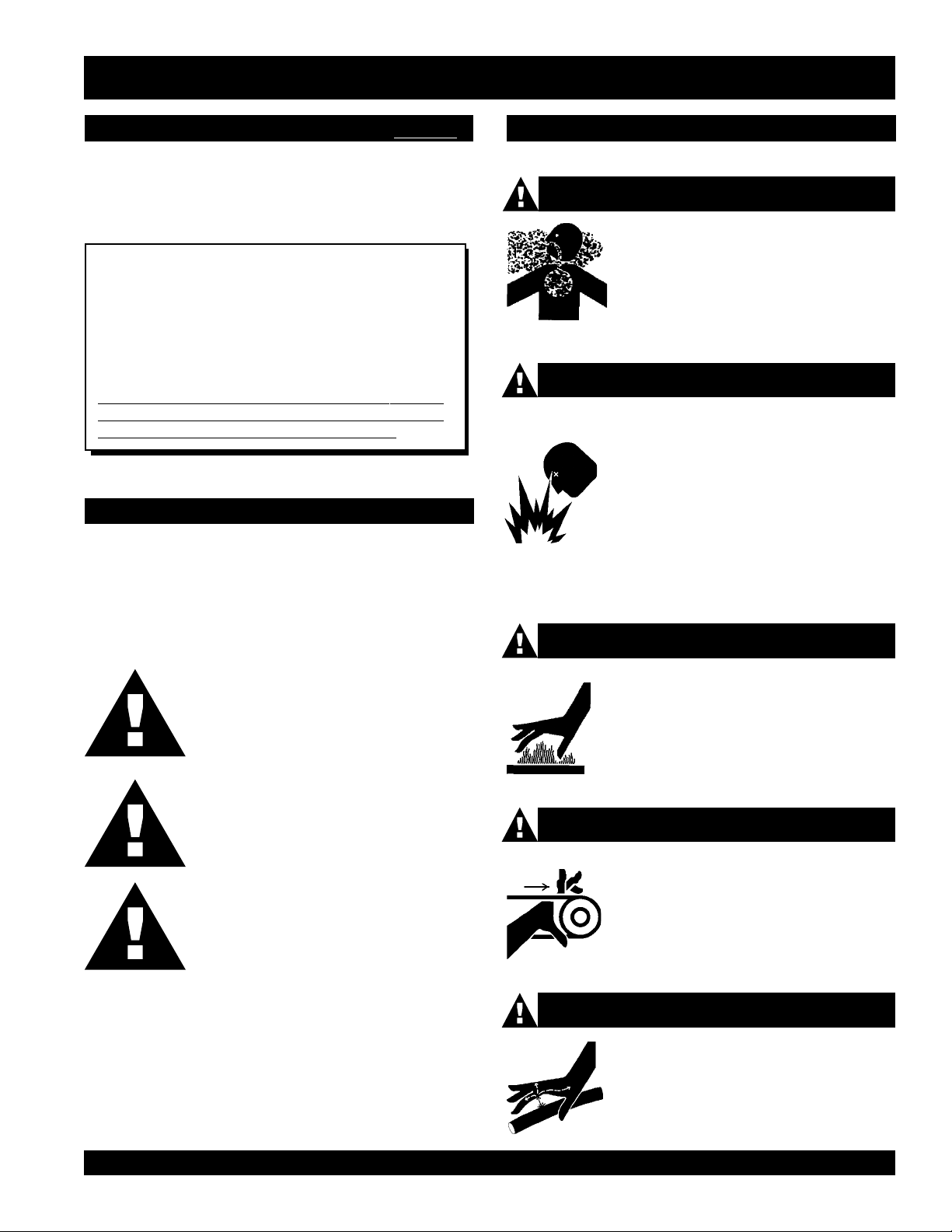
SAFETY MESSAGE ALERT SYMBOLS
The three (3) Safety Messages shown below will inform you
about potential hazards that could injure you or others. The
Safety Messages specifically address the level of exposure to
the operator, and are preceded by one of three words: DANGER,
WARNING, or CAUTION.
Lethal Exhaust Gases
Engine exhaust gases contain poisonous
carbon monoxide. This gas is colorless and
odorless, and can cause death if inhaled.
NEVER operate this equipment in a confined
area or enclosed structure that does not
provide ample free flow air.
Explosive Fuel
Diesel fuel is flammable, and its vapors can
cause an explosion if ignited. DO NOT start
the engine near spilled fuel or combustible
fluids. DO NOT fill the fuel tank while the
engine is running or hot. DO NOT overfill
tank, since spilled fuel could ignite if it comes
into contact with hot engine parts or sparks
from the ignition system. Store fuel in approved
containers, in well-ventilated areas and away
from sparks and flames. NEVER use fuel as
a cleaning agent.
Burn Hazards
DANGER: You WILL be KILLED or
SERIOUSLY injured if you DO NOT follow
directions.
WARNING: You CAN be KILLED or
SERIOUSLY injured if you DO NOT follow
directions.
CAUTION: You CAN be injured if you
DO NOT follow directions.
Potential hazards associated with STX-SERIES Ride-on Power
Trowel operation will be referenced with Hazard Symbols which
appear throughout this manual, and will be referenced in
conjunction with Safety Message Alert Symbols.
Engine components can generate extreme heat.
To prevent burns, DO NOT touch these areas
while the engine is running or immediately after
operations. NEVER operate the engine with
heat shields or heat guards removed.
Rotating Parts
NEVER operate equipment with covers, or
guards removed. Keep fingers, hands, hair
and clothing away from all moving parts to
prevent injury.
Skin Injection Hazard
NEVER use your hand to find hydraulic leaks.
Use a piece of wood or cardboard. Hydraulic
fluid injected into the skin must be treated by
a knowledgable physician immediately or
severe injury or death can occur.
STX-SERIES • RIDE-ON POWER TROWEL — OPERATION MANUAL — REV. #1 (07/16/04) — PAGE 7
/02) — PAGE 7
Page 8
STX-SERIES — SAFETY MESSAGE ALERT SYMBOLS
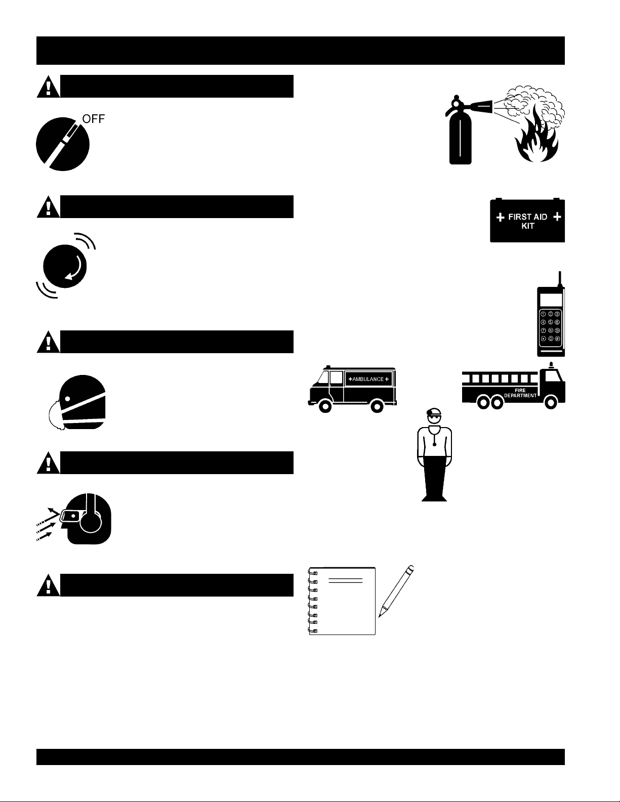
Accidental Starting
ALWAYS place the ON/OFF switch in the
OFF position, and remove the key.
Over Speed Conditions
NEVER tamper with the factory settings of the
engine governor or settings. Personal injury
and damage to the engine or equipment can
result if operating in speed ranges above
maximum allowable.
Respiratory Hazard
EMERGENCIES
■
ALWAYS know the location of
the nearest
■
ALWAYS know the location of the
nearest and
■
In emergencys
nearest phone or
Also know the phone numbers of the nearest
ambulance, doctor
information will be invaluable in the case of an
emergency.
fire extinguisher
first aid kit
always
keep a phone on the job site
and
.
.
know the location of the
.
fire department
. This
ALWAYS wear approved respiratory
protection.
Sight and Hearing hazard
ALWAYS wear approved eye and hearing
protection.
Equipment Damage Messages
NOTE
Other important messages are provided throughout this manual
to help prevent damage to your trowel, other property, or the
surrounding environment.
This Ride-On Power Trowel, other
property, or the surrounding
environment could be damaged if
you do not follow instructions.
PAGE 8 — STX-SERIES • RIDE-ON POWER TROWEL — OPERATION MANUAL — REV. #1 (07/16/04)
)
Page 9

STX-SERIES — RULES FOR SAFE OPERATION
CAUTIONCAUTION
CAUTION
CAUTIONCAUTION
Failure to follow instructions in this manual may
lead to serious injury or even death! This
equipment is to be operated by
qualified personnel only! This equipment is
for industrial use only and should not be
regarded as a toy.
The following safety guidelines should always be used when
operating the STX-SERIES Ride-on Power Trowel:
GENERAL SAFETY
■
DO NOT operate or service this equipment before reading
this entire manual.
■
This equipment should not be operated by persons under
18 years of age.
■
DO NOT operate this equipment unless all guards and safety
devices are attached and in place.
■
ALWAYS use proper
equipment. This ride-on trowel is very heavy. It should be
lifted only with a lifting device (i.e. crane, forklift, etc.) with a
lifting capacity of at least one ton.
■
ALWAYS check to make sure that the operating area is clear
before starting the engine.
■
ALWAYS test the safety
the equipment.
■
NEVER place your feet inside the guard rings while starting
or operating this equipment.
■
NEVER operate this equipment without proper
clothing, shatterproof glasses, steel-toed boots and other
protective devices required by the job. Avoid wearing jewelry
or loose fitting clothing that may snag on the controls or
moving parts, this can cause a serious injury.
heavy
lifting techniques when moving
safety stop switch
trained and
before operating
protective
Maintenance Safety
■
Disconnect the battery and spark plug wires before attempting
any type of service.
■
Securely support any machine components that must be
raised.
■
NEVER lubricate components or attempt service on a running
machine.
■
ALWAYS allow the machine a proper amount of time to cool
before servicing.
■
Keep the machinery in proper running condition.
■
Make sure that there is no buildup of concrete, grease, oil or
debris on the machine.
■
Fix damage to the machine immediately and always replace
broken parts.
■
Dispose of hazardous waste properly. Examples of
potentially hazardous waste are used motor oil, fuel and
fuel filters.
■
DO NOT use food or plastic containers to dispose of
hazardous waste.
■
DO NOT pour waste, oil or fuel directly onto the ground,
down a drain or into any water source.
■
High Temperatures – Allow the machine
and engine to cool before adding fuel or
performing service and maintenance
hot
functions. Contact with
cause serious burns.
components can
■
ALWAYS keep clear of rotating or moving parts while
operating this equipment.
■
NEVER leave the machine
■
ALWAYS refuel in a well-ventilated area, away from sparks
and open flames.
■
ALWAYS use extreme caution when working with
. When refueling,
liquids
.
DO NOT smoke around or near the machine. Fire or
cool
explosion could result from flames or sparks, or if fuel is spilled
on a hot engine.
■
Moving Parts – Shut down the engine before performing
service or maintenance functions. Contact with moving parts
can cause serious injury.
STX-SERIES • RIDE-ON POWER TROWEL — OPERATION MANUAL — REV. #1 (07/16/04) — PAGE 9
unattended
stop the
engine and allow it to
while running.
flammable
/02) — PAGE 9
Page 10

STX-SERIES — OPERATION AND SAFETY DECALS
OPERATION AND SAFETY DECALS
The STX-SERIES Ride-on Power Trowel is equipped with a number of operation and safety decals. These decals are provided for
operator safety and maintenance information. Table 1 below illustrates these decals as they appear on the machine. Should any of
these decals become unreadable, replacements can be obtained from your dealer.
PAGE 10 — STX-SERIES • RIDE-ON POWER TROWEL — OPERATION MANUAL — REV. #1 (07/16/04)
)
Page 11

STX-SERIES — SPECIFICATIONS
Figure 1. STX-SERIES Dimension /Specifications
)mc(.ni–htgneL–A )813(521
)mc(.ni–htdiW–B )561(0.56
1
)mc(.ni–thgieH–C
gnitarepO).sgk(.sbl–thgieW )909(000,2
gnippihS).sgk(.sbl–thgieW )7311(0052
2
ABd–erusserPdnuoS
2
s/tf–noitarbiV
NOTE:
1. This value includes the seat height.
2. Sound pressure is a weighted measure. Measured at the
operators ear position while the ride-on trowel is operating
at full throttle on concrete in a manner most often
experienced in “
normal
” circumstances. Sound pressure
may vary depending upon the condition of the concrete.
Hearing protection is always recommended.
3. The vibration level indicated is the maximum RMS (Root
Mean Square) value obtained at the handle grip while
operating the ride-on trowel on curing concrete in a manner
2)3
s/m(
)s/m(MPF–deepSpiTedalB )9.9(4291
.P.H–enignE degrahcobruTleseiD,ereeDnhoJ55
)sretil(snollag–knaTleuF )54(21
MPR–rotoR 031ot0
)mc(.ni–htdiWhtaP )792(711
4
liOciluardyH
most often experienced in “
were obtained from all three axes of motion. The values
shown represent the maximum RMS value from these
measurements.
4. “AW” stands for
viscosity
is similar to 10W-30-motor oil. It is recommended that AW
MV 68 hydraulic oil be used. If this type of hydraulic oil is
not available then use 10W-30 engine oil (cold weather)
or 10W-40 engine oil (hot weather).
snoitacificepSseireS-XTS.2elbaT
6LSCTDJ55XTS
)241(0.65
79
)5.2(0.8<
4
86VMWA
)rehtaewtoh04-W01(
)rehtaewdloc03-W01(
normal
anti-wear
” circumstances. Values
and “MV” stands for
. The 68 refers to the general viscosity range and
multi-
STX-SERIES • RIDE-ON POWER TROWEL — OPERATION MANUAL — REV. #1 (07/16/04) — PAGE 11
/02) — PAGE 11
Page 12

STX-SERIES — GENERAL INFORMATION
GENERAL INFORMATION
The STX-SERIES Ride-On Power Trowels are designed for the
floating and finishing of concrete slabs.
Take a walk around the STX-SERIES Ride-On Power Trowel.
Take notice of all the entire major components (see Figures 2
and 3, pages 13 and 14) like the engine, blades, air cleaner,
ignition switch etc. Check that there is always oil in the engine,
and hydraulic oil in the hydraulic oil reservoir.
Read all the safety instructions carefully. Safety instructions will
be found throughout this manual and on the machine. Keep
all safety information in good, readable condition. Operators
should be well trained on the operation and maintenance of
the STX-SERIES Ride-On Power Trowel.
Before using your STX-SERIES Ride-On Power Trowel, test it
on a flat watered down section of finished concrete. This trial test
run will increase your confidence in using the trowel and at the
same time it will familiarize you with the trowel’s controls and
indicators. In addition you will understand how the trowel will
handle under actual conditions.
Engine
Dual palm grip joystick controls located to the left and right of the
operator are provided for steering the STX-SERIES Ride-on
Power Trowel. The joysticks are linked to three hydraulic steering
cylinders located within the frame of the machine. Detailed
explanation of how the joystick controls affect the steering of the
trowel can be found in Table 3, on page 18.
Hydraulic Pump
Delivers a continuous controlled flow of hydraulic fluid to the
hydraulic motors.
CAUTIONCAUTION
CAUTION
CAUTIONCAUTION
This Ride-on Power Trowel is very
and awkward to move around. Use proper
heavy lifting procedures and DO NOT attempt
to lift the Ride-on Power Trowel by the guard
rings.
heavy
The STX-SERIES Ride-On Power Trowel is available with a
standard 55hp John Deere diesel engine. Refer to the engine
owner’s manual for specific instructions regarding engine
operation. Please contact your nearest Multiquip Dealer for a
replacement should the original manual disappear or become
otherwise unusable.
Blades
The blades of the Ride-on Power Trowel finish the concrete as
they are swirled around the surface. Blades are classified as
float (10 or 8 inches wide), and finish (6 inches wide). The STXSERIES is equipped with six blades per rotor equally spaced in
a radial pattern and attached to vertical rotating shaft by means
spider assembly.
of a
Hydraulic Motor
Independent hydrostatic drive motors are coupled to the enginepowered hydrostatic pumps. Each motor drives a spider
assembly.
Moving the Ride-On Trowel
The STX-SERIES Ride-on Power Trowel is designed to be moved
and handled several ways. The easiest way to lift the ride-on
trowel is to utilize the lift loops that are welded to the frame.
These lift loops are located to the left and right sides of the
operator’s seat (Figure 2, Page 13).
A strap or chain can be attached to these lift loops, allowing a
forklift or crane to lift the Ride-on Power Trowel up onto a slab of
concrete. The strap or chain should have a minimum 2,000
pounds (1000-kg) lifting capacity and the lifting gear must be
capable of lifting at least this amount.
Training
For proper training, please use the “TRAINING CHECKLIST”
located in the front of this manual (Page 5). This checklist will
provide an outline for an experienced operator to provide training
to a new operator.
Hydraulic Steering
PAGE 12 — STX-SERIES • RIDE-ON POWER TROWEL — OPERATION MANUAL — REV. #1 (07/16/04)
)
Page 13

STX-SERIES — CONTROLS AND COMPONENTS
Figure 2. STX-SERIES Controls and Components (Front)
Figures 2 and 3 (pages 13 and 14) show the location of the
controls, indicators and general maintenance parts. The function
of each control, indicator or maintenance part is explained below:
1. Seat – Place for operator to sit. Trowel blades will not
rotate unless operator is seated. Seat is adjustable.
2. Trowel Speed Limiter Control – Used to adjust the
maximum trowel speed that can be obtained when the foot
pedal is fully depressed.
3. Hour Meter – Indicates number of hours machine has
been used.
4. Throttle Control Lever – Controls the speed of the engine.
Move the hand lever forward to increase engine speed
(high), backwards to decrease engine speed (low).
5. Operator Gauges – Allows operator to monitor engine,
hydraulic and electrical functions.
6. Ignition Switch – With key inserted turn clockwise to start
engine.
7. Light Switch – When activated, turns on six halogen lights.
Lights offer better visibility when working indoors.
8. Lights – Six low voltage halogen lights are provided with
this unit.
9. Toolbox Compartment – Storage for tools.
10. Spray Nozzles – Spray nozzle for retardant. Two spray
nozzles are supplied with this unit.
11. Foot Pedal – Controls blade speed. Slow blade speed is
accomplished by slightly depressing the foot pedal.
Maximum blade speed is accomplished by fully depressing
the foot pedal.
12. Removable Steps (left & right) – Provides for safe footing
for mounting and dismounting trowel. When removed,
provides access to spider and blade assemblies.
13. Retardant Spray Control Buttons (left & right) – When
pressed allows retardant spray to flow through the spray
nozzle located at the front of the machine.
14. Hand Holds – Use to assist safe mounting and dismounting
trowel.
15. Lift Loops – Located on both the left and right sides of the
main frame. Used when the trowel must be lifted onto a
concrete slab.
16. Pitch Block – (Behind grill guard.) Measure and adjust
pitch pressure at the pitch block.
17. Fuel Gauge/Filler Cap – Indicates the amount of fuel in
the fuel tank. Remove this cap to add fuel.
18. Overflow Bottle – (Behind grill guard.) Supplies water or
coolant to the radiator when radiator water or coolant level
is low. Fill to indicated level as shown on bottle.
19. Hydraulic Reservoir – Part of frame. Holds hydraulic oil
necessary for pump operation.
STX-SERIES • RIDE-ON POWER TROWEL — OPERATION MANUAL — REV. #1 (07/16/04) — PAGE 13
/02) — PAGE 13
Page 14

STX-SERIES — CONTROLS AND COMPONENTS
Figure 3. STX-SERIES Controls and Components (Rear)
20. Documentation Box – Storage for documentation and
other information regarding the trowel.
21. Battery – Provides +12V DC power to the electrical system.
22. Hydraulic Oil Sight Glass – Indicates the level of the
hydraulic oil in the reservoir.
23. Hydraulic Suction Filter – Filters hydraulic fluid prior to
entering the system. (10 Micron absolute synthetic media.)
24. Hydraulic Oil Expansion Tank – Accommodates
expanding hydraulic oil as it gets hot. The oil gravity flows
back to the reservoir as it cools down, therefore NEVER
open the the Hydraulic Oil Filler Cap (Item 30) when the
system is warm and the oil has expanded.
25. Steering Control (left side) – Allows the unit to move in a
forward or reverse direction only.
26. Blade Pitch Control Switch (left side) – Adjusts the left
27. Blade Pitch Control (Twin Pitch) – Adjusts the blade
28. Steering Control (right side) – Allows the unit to move in
29. Grill Guards (left & right) – Protects operator from moving
30. Hydraulic Oil Filler Cap – Remove this cap to add
31. Retardant Spray Tank – Holds 5 gallons of retardant,
side blade pitch independently of the right side.
pitches simultaneously.
either a forward, reverse left or right direction.
components. Remove for maintenance access.
hydraulic oil. Open ONLY when system is cooled down
and all expanded oil has returned to the reservoir.
water, or other liquid.
PAGE 14 — STX-SERIES • RIDE-ON POWER TROWEL — OPERATION MANUAL — REV. #1 (07/16/04)
)
Page 15

PRE-INSPECTION
STX-SERIES — PRE-INSPECTION
The following sections are intended
to assist the operator with pre-
NOTE
in the field. DO NOT use your Ride-On Power Trowel until these
sections are thoroughly understood.
CAUTIONCAUTION
CAUTION
CAUTIONCAUTION
Failure to understand the operation of the
STX-SERIES Ride-On Power Trowel could
result in severe damage to the trowel or
personal injury.
See Figures 2 and 3 (Pages 13 and 14) for the location of controls
and indicators referenced in this manual.
Engine Oil
inspection and the initial start-up of
the STX-SERIES Ride-On Power
Trowel. It is extremely important that
these sections are read carefully
before attempting to use the trowel
CAUTIONCAUTION
CAUTION
CAUTIONCAUTION
CAUTIONCAUTION
CAUTION
CAUTIONCAUTION
(FILL TO OVERFLOW WITH
HYDRAULIC SYSTEM COOL)
Figure 5. Hydraulic Oil Sight Glass
Hydraulic oil can get HOT!
ALWAYS allow hydraulic oil to cool before
removing fill cap.
Removal of the fill cap when oil fills the sight
glass will cause hydraulic oil to spill. Clean
up hydraulic oil spills immediately.
1. Pull the engine oil dipstick from its holder.
2. Determine if engine oil is low (Figure 4), add correct amount
of engine oil to bring oil level to a normal safe level.
Figure 4. Engine Oil Dipstick Figure 6. Fuel Gauge
Hydraulic Oil
Determine if the hydraulic oil is low by observing the level of oil
in the hydraulic Oil Sight Glass (Figure 5). The hydraulic tank
has an elevated overflow bottle. DO NOT remove the fill cap
when the oil is hot or spillage will occur.
Fuel
Determine if the engine fuel is low (Figure 6). If
fuel level is low, remove the fuel filler cap and
fill with diesel fuel. Handle fuel safely. Motor
fuels are highly flammable and can be
dangerous if mishandled. DO NOT smoke while
refueling. DO NOT attempt to refuel the ride-on
trowel if the engine is hot or running.
CAUTIONCAUTION
CAUTION
CAUTIONCAUTION
NEVER store the Ride-On Power Trowel with
fuel in the tank for any extended period of
time. ALWAYS clean up spilled fuel
immediately.
STX-SERIES • RIDE-ON POWER TROWEL — OPERATION MANUAL — REV. #1 (07/16/04) — PAGE 15
/02) — PAGE 15
Page 16

STX-SERIES — INITIAL START-UP
INITIAL START-UP
CAUTIONCAUTION
CAUTION
CAUTIONCAUTION
NEVER operate the trowel
in a confined area or
enclosed area structure
that does not provide ample
free flow of air.
ALWAYS wear approved eye and hearing
protection before operating the ride-on power
trowel.
NEVER place hands or feet inside the guard
rings while the engine is running. ALWAYS
shut the engine down before performing any
kind of maintenance service on the trowel.
CAUTIONCAUTION
CAUTION
CAUTIONCAUTION
NEVER disable or disconnect the
Stop Switch
safety and injury may result if it is disabled,
disconnected or improperly maintained.
3. It is recommended that the operation of the
Switch
operations. Doing this will verify that the switch is working
properly and presents no danger to the operator.
4. Place the
position.
is checked prior to performing any troweling
engine throttle lever (
. It is provided for the operators’
Figure 7) in the
Safety
Safety Stop
LOW
Starting the Engine
1. With one foot on the ground and the other foot placed on
the trowel’s platform, grasp the grab handles lifting yourself
onto the trowel. Then sit down in the operator’s seat.
Figure 7. Engine Throttle Control Lever (Low)
CAUTIONCAUTION
CAUTION
CAUTIONCAUTION
DO NOT grab hold of the joysticks to lift
yourself onto the trowel. Pulling on the
joysticks repeatedly will weaken the units.
Always use the grab handles to lift yourself
on the trowel.
2. The STX Ride-On Power Trowel is equipped with a
Stop Switch
is sitting in the seat. While the engine can be started or
continue to run with the operator off the seat, the rotors will
not rotate. The weight of an operator activates a switch
within the seat allowing the rotors to turn.
. The trowel will not move unless an operator
Safety
5. Insert the
HIGH
LOW
ignition key
Figure 8. Ignition Switch and Key
into the ignition switch (Figure 8).
PAGE 16 — STX-SERIES • RIDE-ON POWER TROWEL — OPERATION MANUAL — REV. #1 (07/16/04)
)
Page 17

STX-SERIES — INITIAL START-UP
6. Turn the ignition key clockwise to the (start) position. The
oil
and charge indicator lights (Figure 9) should be on.
Figure 9. Oil and Charge Indicator Lights
cold
weather turn and hold the
NOTE
In
ignition key counter clockwise to the
preheat position, wait until the
preheat indicator goes off before
turning the ignition key clockwise to
the start position. Two or three
preheat cycles may be necessary in
very cold weather.
7. Turn ignition key fully clockwise and listen for engine to
start. Once engine has started release ignition key. Let
engine warm for a few minutes.
8. Place the
engine throttle lever
(Figure 11) in the
HIGH
position.
9. The engine should be running at full RPM.
10. Repeat this section a few times to get fully acquainted with
the engine starting procedure.
LO
W
Figure 10. Engine Throttle Control Lever (High)
STX-SERIES • RIDE-ON POWER TROWEL — OPERATION MANUAL — REV. #1 (07/16/04) — PAGE 17
/02) — PAGE 17
Page 18

OPERATION
The following section is intended as
a basic guide to the Ride-On Power
NOTE
Trowel operation, and is not to be
considered a complete guide to
concrete finishing. It is strongly
suggested that all operators
(experienced and novice) read “
Slabs on Grade
” published by
the American Concrete Institute, Detroit Michigan.
Steering
STX-SERIES — OPERATION
Two joysticks (Figures 11 and 12) located to the left and right of
the operator’s seat provide directional control for the STXSERIES Ride-On Power Trowel. Table 3 illustrates the various
directional positions of the joysticks and their effect on the rideon trowel.
NOTE
All directional references with
respect to the joysticks are from
the
operator’s
seat position.
See Table 3 for steering and directional relationship to Joystick
Control movement.
Figure 12. Right Joystick Control
NOITCERID&KCITSYOJ STLUSER
evoM TFEL kcitsyoJ
drawroF
evoM TFEL kcitsyoJ
drawkcaB
evoM THGIR kcitsyoJ
drawroF
evoM THGIR kcitsyoJ
drawkcaB
evoM HTOB skcitsyoJ
drawroF
ehtylnosesuaC
ehtfoedisthgir
otlewortno-edir
.drawrofevom
ehtylnosesuaC
ehtfoedisthgir
otlewortno-edir
.drawkcabevom
gninoitisoPlanoitceriDkcitsyoJ.3elbaT
ehtylnosesuaC
ehtfoedistfel
otlewortno-edir
.drawrofevom
ehtylnosesuaC
ehtfoedistfel
otlewortno-edir
.drawkcabevom
lewortno-edirehtsesuaC
nidrawrofevomot
.enilthgiartsa
evoM HTOB skcitsyoJ
Figure 11. Left Joystick Control
evoM THGIR kcitsyoJ
evoM THGIR kcitsyoJ
drawkcaB
thgiRehtot
tfeLehtot
PAGE 18 — STX-SERIES • RIDE-ON POWER TROWEL — OPERATION MANUAL — REV. #1 (07/16/04)
)
lewortno-edirehtsesuaC
drawkcabevomot
.enilthgiartsani
lewortno-edirehtsesuaC
.thgirehtotevomot
lewortno-edirehtsesuaC
tfelehtotevomot
Page 19

STX-SERIES — OPERATION
1. The foot pedal (Figure 13) solely controls blade speed.
The position of the foot pedal determines the blade speed.
Slow blade speed is obtained by slightly depressing the
pedal. Maximum blade speed is obtained by fully
depressing the pedal.
5. Practice maneuvering the Ride-on Power Trowel using the
information listed in Table 3. Try to practice controlled
motions as if you were finishing a slab of concrete. Practice
edging and covering a large area
6. Try adjusting the pitch of the blades. This can be done with
the ride-on trowel stopped or while the trowel is moving,
whatever feels comfortable. Test the operation of optional
equipment like retardant spray and lights if equipped.
7. Pull both the left and right joysticks backward (Figure 15)
and repeat steps 3 through 6 while substituting the word
reverse for forward.
Figure 13. Blade Speed Control Foot Pedal
2. Push both the left and right joysticks forward (Figure 14).
Figure 15. Joystick Control Reverse Direction
Trowel Speed Limiter Control
The speed limiter control located on the control panel (Figure
16) can be used to adjust the maximum trowel speed that can be
obtained when the foot pedal is fully depressed. Pull up to reduce
the maximum speed and push down to return to full speed. For
fine adjustments, rotate the knob clockwise or counter-clockwise.
Figure 14. Joystick Control Forward Direction
3. With your right foot, slowly depress the right foot pedal
halfway. Notice that the ride-on power trowel begins to move
E
A
S
in a forward direction. Release both joystick controls to
stop forward movement then remove your right foot from
the foot pedal.
4. Practice holding the machine in one place as you increase
blade speed. When about 75% of maximum blade speed
has been reached, the blade will be moving at proper
finishing speed. The machine may be difficult to keep in
one place. Trying to keep the ride-on trowel stationary is a
good practice for operation.
D
L
E
O
H
D
L
O
H
LOW
Figure 16. Trowel Speed Limiter Control
STX-SERIES • RIDE-ON POWER TROWEL — OPERATION MANUAL — REV. #1 (07/16/04) — PAGE 19
/02) — PAGE 19
Page 20

STX-SERIES — OPERATION
Blade Pitch Control
The trowel blades can be pitched for various finishing operations
with the two rocker switches located on the left control panel
Engine Shut-Down
1. Return the speed control lever (Figure 19) to low idle, and
allow the engine to idle for 5 minutes .
next to the left joystick control (Figure 17).
Figure 17. Blade Pitch Control
The right switch pitches both blades at the same time while the
left switch will pitch only the left blade. Moving the switches
forward increases the pitch while moving them backward
decreases the pitch, (Figure 18).
NOTE
HIGH
LOW
Figure 19. Blade Pitch Control
Failure to allow the engine to idle
for 5 minutes before shutting engine
OFF
may lead to turbocharger
damage.
LEFT
PITCH
ONLY
MORE PITCH
LESS PITCH
TWIN
PITCH
BLADES TO BE FLA T
WITH FLOAT P ANS
Figure 18. Blade Pitch Rocker Switches
Important! To get the blades absolutely flat for using float
pans follow these steps:
1. TWIN PITCH all the way DOWN.
2. LEFT PITCH up a little ways.
3. TWIN PITCH all the way DOWN, again.
4. LEFT PITCH all the way DOWN.
2. Turn the ignition key counter-clockwise to the "
switch contact
" position, then remove the key.
starter
3. Clean and remove any foreign debris from the trowel.
PAGE 20 — STX-SERIES • RIDE-ON POWER TROWEL — OPERATION MANUAL — REV. #1 (07/16/04)
)
Page 21

STX-SERIES — MAINTENANCE
MAINTENANCE
See the engine manual supplied with
NOTE
your machine for appropriate engine
maintenance schedule and
troubleshooting guide for problems.
At the front of the book (Page 6) there is a “Daily Pre-Operation
Checklist”. Make copies of this checklist and use it on a daily
basis.
CAUTIONCAUTION
CAUTION
CAUTIONCAUTION
Disconnect battery cables
before attempting any
service or maintenance on
the Ride-on Power Trowel.
ALWAYS allow the engine
to cool before servicing. NEVER attempt any
maintenance work on a hot! (muffler, radiator,
etc.) trowel.
Maintenance Schedule
Change
use, then change every 250 hours.
Daily (8-10 Hours)
the
hydraulic oil
and
filter
after the first 100 hours of
MAINTENANCE PROCEDURES
Checking/Adjusting Trowel Speed
Because the two hydraulic drive motors operate independent of
each other, the trowel speed between them may vary. If the unit’s
steering is difficult to control, or if one spider is spinning noticeably
faster or slower than the other, the trowel speed may need to be
checked. It is also recommended that the trowel speed be
checked at least once a year.
Trowel speed adjustment is a two-step process. First, the left
side should be checked and/or adjusted. Second, the right side
should be adjusted to match the left.
Left Side Trowel Speed Adjustment
The left side trowel speed is adjusted by the set bolt located
under the operator's platform (Item A, Figure 20) and accessed
by opening the storage panel door. Backing the set screw out
decreases the left side trowel speed; screwing it inward increases
the speed.
A
1. Check fluid levels in engine and reservoir; fill as necessary.
Weekly (30-40 Hours)
2. Relube arms, thrust collar and clutch.
3. Replace blades if necessary.
4. Check, clean, or replace the engine air filter as necessary.
5. Replace engine oil and filter as necessary, see engine
manual.
Monthly (100-125 Hours)
Remove, clean, reinstall and relube the arms and thrust collar.
Adjust the blade arms.
Yearly (500-600 Hours)
1. Check and replace if necessary the arm bushings, and
thrust collar bushings.
2. Adjust blade speed.
3. Replace hydraulic fluid and hydraulic filter.
NOTE
Change
after the first 100 hours of use, then
change every 250 hours.
the
hydraulic oil
and
filter
Right Side Trowel Speed Adjustment
The right side trowel speed is adjusted by changing the length
of the connecting rod on the pump actuation levers (Figure 21).
Figure 20. Trowel Speed Control
Figure 21. Pump Connecting Rod & Levers
STX-SERIES • RIDE-ON POWER TROWEL — OPERATION MANUAL — REV. #1 (07/16/04) — PAGE 21
/02) — PAGE 21
Page 22

STX-SERIES — MAINTENANCE
This rod is basically a turnbuckle (Figure 22). Rotating it in one
direction increases the length and corresponding trowel speed.
Rotating it the opposite direction decreases the length and trowel
speed. The right side trowel speed should be within 3 rpm of the
left.
Matching Blade Pitch for Both Sets of Blades
Sometimes it may be necessary to match blade pitch between
the left and right sets of blades. There are some signs that this
may be necessary. For example, the differences in pitch can
cause a noticeable difference in finish quality between the left
and right sets of blades. The difference in blade pitch can also
make the machine difficult to control. This is due to the surface
area in contact with the concrete (the blade set with the greater
contact area tends to stick to the concrete more).
To synchronize pitch on both sides, the left blade assembly can
be pitched by itself. By using the electric blade pitch rocker
switches, (Figure 23) the pitch can be syncronized on the left
and the right sides.
Figure 22. Turnbuckle & Adjustment Nuts
Figure 23. Blade Pitch Rocker Switches
LEFT
MORE PITCH
PITCH
ONL Y
LESS PITCH
BLADES TO BE FLAT
WITH FLOA T PANS
TWIN
PITCH
A good starting point in the adjustment process is to adjust the
rod such that both trowels begin to rotate at the same time when
the foot pedal is slowly depressed. This will, generally, get the
speeds fairly close; close enough for use if instrumentation is
unavailable (i.e. on the job site). From this point on, some form of
instrumentation is required to verify that the trowel speeds are
within tolerance. A strobe or magnetic pickup type speed indicator
is recommended to verify the speeds.
The trowel speeds should be adjusted on a dry concrete floor
with the blades pitched flat. Units with the John Deere
Blade Pitch Adjustment Procedure
The maintenance adjustment of blade pitch is an adjustment
that is made by a bolt (Figure 24) on the arm of the trowel blade
finger. This bolt is the contact point of the trowel arm to the lower
wear plate on the thrust collar. The goal of adjustment is to promote
consistent blade pitch and finishing quality.
Watch for the following indications when determining if blade
pitch adjustments are necessary:
turbocharged engine should be set at 130-135 RPM with the
engine at full speed.
■
Is the machine wearing out blades unevenly (i.e. one blade
is completely worn out while the others look new)?
■
Does the machine have a perceptible rolling or bouncing
motion when in use?
■
Look at the machine while it is running, do the guard rings
“rock up and down” relative to the ground?
PAGE 22 — STX-SERIES • RIDE-ON POWER TROWEL — OPERATION MANUAL — REV. #1 (07/16/04)
)
Page 23

STX-SERIES — MAINTENANCE
Adjustments are made by tightening or loosening the blade pitch
adjustment bolt (Figure 24).
Figure 24. Blade Pitch Adjustment Bolt
1. Spider Plate
2. Blade Pitch Adjustment Bolt
3. Trowel Lever
4. Trowel Arm
5. Trowel Blade
The easiest and most consistent way to make this adjustment is
to use the Trowel Arm Adjustment Fixture (P.N. 9177) that is
manufactured by Whiteman Industries. This fixture will allow
consistent adjustment of the trowel arm fingers. It comes with all
the hardware necessary to properly accomplish this maintenance
and instructions on how to properly utilize this tool. Adjusting the
trowel arm fingers without a fixture requires a special talent.
Changing A Blade
It is recommended that all the blades on the entire machine are
changed at the same time. If only one or some of the blades are
changed at one time, the machine will not finish concrete
consistently and the machine may wobble or bounce.
1. Place the machine on a flat, level surface. Adjust the blade
pitch control to make the blades as flat as possible. Note
the blade orientation on the trowel arm. This is important
for ride-on trowels as the two sets of blades counter-rotate.
Lift the machine up, placing blocks under the main guard
ring to support it.
2. Remove the bolts and lock washers on the trowel arm, and
then remove the blade. (Access is easier if the steps are
removed.)
3. Scrape all concrete and debris from the trowel arm. This is
important to properly seat the new blade.
4. Install the new blade, maintaining the proper orientation
for direction of rotation.
5. Affix the bolts and lock washers.
6. Torque to 9 ft. lbs.
7. Repeat steps 2-6 for all remaining blades.
If a trowel arm adjustment fixture is not available and immediate
adjustment is necessary; we suggest the following procedure. If
you can see or feel which blade is pulling harder, adjust the bolt
that corresponds to that blade. Another way to determine which
blades need adjustment is to place the machine on a flat surface
and pitch the blades as flat as possible. Now, look at the
adjustment bolts. They should all barely make contact with the
lower wear plate on the spider. If you can see that one of them is
not making contact; some adjustment will be necessary.
It will be possible to adjust the “high” bolts down to the level of
the one that is not touching, or adjust the “low” bolt up to the level
of the higher ones. If possible, adjust the low bolt up to the level
of the rest of the bolts. This is the fastest way, but may not always
work. Verify that after adjustment, the blades pitch correctly. Often
times, if the blades are incorrectly adjusted, they will not be able
to pitch flat. This occurs when the adjusting bolts have been
raised too high. Conversely, sometimes the adjusting bolts are
too low and the blades cannot be pitched high enough for
finishing operations.
STX-SERIES • RIDE-ON POWER TROWEL — OPERATION MANUAL — REV. #1 (07/16/04) — PAGE 23
/02) — PAGE 23
Page 24

STX-SERIES — MAINTENANCE
Checking Hydraulic Pressure
Many hydraulic problems are a result of low fluid levels. Before
checking any other possibilities, make sure the hydraulic fluid
level is up to the top of the sight glass which is located at the
back/center of the frame.
Hydrostatic pressure can be checked using a pressure gauge
with a range of at least 5,000 psi. Two male diagnostic quick
couplers (one for each pump) are located beneath the right grill
guard. To access couplers (Item B, Figure 26), remove the grill
guard. It is best to use two gauges simultaneously (Figure 25),
but it is possible to use only one gauge and repeat the procedure
for each side.
To fully test the hydrostatic system, the spiders will need to be
locked so that they cannot rotate. This can be done by wrapping
a chain around an arm on each spider, thus chaining them
Once the pressure gauges are installed and the spiders chained
together, the system can be checked.
With the foot pedal in the idle position and the engine at full
speed, the pressure should be 200 to 300 psi. If the pressure is
less than 200 psi, the charge system may need to be inspected
and/ or serviced. In particular, the suction filter and charge pump
relief valve should be checked. The suction filter may be plugged,
or the relief valve may be stuck. Either condition may cause low
charge pressure.
With the engine at 50% to 70% of full speed, and spiders chained
together, slowly depress the foot pedal and read the gauges.
The pressure should get to at least 4,350 psi (300 bar). If the
pressure will not attain 4,350 psi (300 bar), the pump should be
inspected and/or serviced by an authorized service
representative.
together in the back of the trowel.
PRESSURE GAUGE
5000 PSI RANGE
PRESSURE GAUGE
5000 PSI RANGE
2000
3000
1000
200
150
100
50
bar
psi
WIKA
4000
250
300
5000
2000
1000
RIGHT SIDE
HYDROSTATIC
PUMP
TEST PORT
3000
200
150
100
50
bar
psi
WIKA
4000
250
300
5000
USE A PARKER HANNIFIN
LEFT SIDE PUMP
TEST PORT
QUICK DISCONNECT
PD-SERIES DIAGNOSTIC
FEMALE COUPLER
Figure 25. Pressure Gauge (Hydraulic Pump)
PAGE 24 — STX-SERIES • RIDE-ON POWER TROWEL — OPERATION MANUAL — REV. #1 (07/16/04)
)
Page 25

STX-SERIES — MAINTENANCE
Checking Steering Pressure
Steering pressure is also checked at either of the high pressure
diagnostic couplers under the right grill guard. Check steering
pressure at either coupler with a 300-600 PSI gauge.
CAUTIONCAUTION
CAUTION
CAUTIONCAUTION
DO NOT depress the FOOT PEDAL with the
300-600 PSI gauge installed or the gauge
will be ruined.
(Table 4) indicates proper steering pressure. Check with engine
at Full Speed.
Run the engine at full RPM. The steering system's factory setting
is as shown in Table 4, however some operators may prefer a
more responsive steering (higher pressure required) and some
operators may prefer a "softer feel" (lower pressure required).
Steering Pressure Adjustment
Remember, DO NOT depress the foot pedal with the 300-600
PSI gauge installed. Immediate damage to the gauge will occur.
1. Remove right grill guard.
2. Install 300 or 600 PSI gauge (Figure 27).
3. Loosen 1-1/16" jam nut on charge relief valve (Item A,
Figure 28).
erusserPgnireetS.4elbaT
deepSlluFtaenignEhtiWdekcehC
liOlooC ISP052-002
liOtoH ISP002-081
Figure 26. Pressure Check Couplers
4. Use a 1/2" socket to adjust the small hex nut within the
larger hex jam nut (Item B, Figure 28).
5. Adjust to proper steering pressure specifications shown in
Table 4.
6. Retighten jam nut, remove gauge, and reinstall grill guard.
A
B
Figure 27. Steering Pressure Check
STX-SERIES • RIDE-ON POWER TROWEL — OPERATION MANUAL — REV. #1 (07/16/04) — PAGE 25
/02) — PAGE 25
Figure 28. Steering Pressure Adjustment
Page 26

STX-SERIES — MAINTENANCE
A
B
Pitch Pressure Check
Access the pitch block and pitch pressure test port at the rightrear of the trowel (Figure 29). Removal of the right-rear seat
frame panel may be necessary. Pitch pressure must be measured
with a pitch switch
the pitch pressure will be the same as the charge/steering
pressure. Proper pitch pressure is 2300 PSI.
activated
. With pitch switches unactivated,
Pitch Pressure Adjustment
If the pitch pressure check is out of specification, check the
following:
1. Correct hydraulic fluid level.
2. Plugged hydraulic oil filter.
3. Loose or leaky fittings
4. Ruptured/damaged hydraulic lines.
5. Faulty hydraulic pump.
6. Pitch pressure Relief Valve no longer at factory setting.
The Pitch Pressure Relief Valve is SET AT THE FACTORY, and
normally should require no adjustment. If all other systems are
found not to be defective and the pitch relief valve is suspect,
(loosened jam nut for example), the following steps can be used
to adjust the valve.
CAUTIONCAUTION
CAUTION
CAUTIONCAUTION
Figure 29. Pitch Block
1. Install 3000 PSI range pressure gauge to pitch pressure
test port on pitch block (Figure 30).
2. Activate left pitch switch.
3. Flatten blades (bottom out the pitch cylinders).
4. Continue to hold down pitch switch and record pressure.
NEVER allow the pitch pressure to exceed 2700 PSI or equipment
damage may result.
1. Remove right grill guard and right rear seat frame panel.
2. Install 3000 PSI pressure gauge to pitch pressure test port
on pitch block (Figure 30).
3. Loosen jam nut on pitch block relief valve (Item A, Figure
31).
4. Adjust the relief valve (Item B, Figure 31) with allen wrench
to proper pressure (2300 PSI)
5. Tighten jam nut, remove gauge and reinstall grill guard
and frame panel.
Figure 30. Pitch Pressure Check
Figure 31. Pitch Pressure Adjustment
PAGE 26 — STX-SERIES • RIDE-ON POWER TROWEL — OPERATION MANUAL — REV. #1 (07/16/04)
)
Page 27

STX-SERIES — TROUBLESHOOTING
GNITOOHSELBUORT.5ELBAT
MOTPMYS MELBORPELBISSOP NOITULOS
?leuF
tatonrohguorgninnurenignE
.lla
?noitingI
?smelborprehtO .launams’rerutcafunamenignetlusnoC
tonhctiwSpotSytefaS
.gninoitcnuf
?stcatnocdaB .)hctiwsehtsniatnoc(noihsuctaesecalpeR
?sedalB
?redipS
sllor,secnuob“lewortfI
nevenusekamro,etercnoc
.”etercnocnislriws
?snoitcennoceriwesooL .yrassecensaecalpeR.gniriwkcehC
?smraleworttneB
?sgnihsubmraleworT
.yltcerrocgninoitcnuf
.rabedalbehtotlellarapdna
saelgnahctipemasehttateserasedalbllatahtkcehC
.yletaidemmitiecalper,tnebylthgilsnevesismra
otdeilppusgniebleufsierehterusekaM.metsysleufehttakooL
.deggolctonsiretlifleufehttahterusneotkcehC.enigneeht
sidnarewopsahhctiwsnoitingiehttahterusneotkcehC
.nrowylevissecxeton,noitidnocdoognierasedalbniatrecekaM
ehtmorf)mm05("2nahtsselonerusaemdluohssedalbhsiniF
onerusaemdluohssedalbobmoc,egdegniliartehtotrabedalb
thgiartsebdluohsedalbfoegdegniliarT.)mm98("5.3tahtssel
rofelbaliavasiloottnemtsujdadleifA.redipsehttaderusaem
.)tnempiuqElanoitpOees(smralewortehtfotnemtsujdathgieh
ehtfoenofI.smraleworttnebrofylbmessaredipsehtkcehC
ybenodebnacsihT.ssenthgitrofsgnihsubmralewortehtkcehC
"8/1nahteromsierehtfI.nwoddnapusmralewortehtgnivom
ebdluohssgnihsubeht,mraehtfopitehttalevartfo)mm2.3(
.emitemasehttadecalperebdluohssgnihsubllA.decalper
?ralloctsurhT
?gnihsubralloctsurhT
.ralloctsurhtehtnignihsubehtecalper
?nrowgniraebtsurhT
?hctipedalB
?swercSregniFredipS .noitceSecnanetniaMnierudecorpreptsujdA
elbitpecrepasahenihcaM
.gninnurelihwnoitomgnillor
?ekoY
.yrassecenfiecalpeR
.yrassecenfisnoitcurtsni
.yrassecensaekoyecalpeR.pacraeweht
.eerfgninnipssititahteesotgniraebtsurhtehtkcehC
.redipsehtnotignitatorybralloctsurhtehtfossentalfehtkcehC
.ralloctsurhtehtecalper)mm5.0("20.0nahteromybseiravtifI
tlitnactifI.redipsehtnotignikcorybralloctsurhtehtkcehC
,].D.Oralloctsurhtehttaderusaemsa[)mm6.1("61/1nahterom
noitceSecnanetniaMreptsujdA.hctiptnetsisnocrofsedalbkcehC
noylnevesserpekoyehtfosregnifhtobtahterusekamotkcehC
STX-SERIES • RIDE-ON POWER TROWEL — OPERATION MANUAL — REV. #1 (07/16/04) — PAGE 27
/02) — PAGE 27
Page 28

STX-SERIES — TROUBLESHOOTING
)DEUNITNOC(GNITOOHSELBUORT.5ELBAT
MOTPMYS MELBORPELBISSOP NOITULOS
?gniriW
.gnikrowton)lanoitpo(sthgiL
?sthgiL .nekorbfiecalpeR.doogllitserasblubthgilfieesotkcehC
.yrassecensaecalpeR
hctiwsffo/noretsamehtgnidulcni,snoitcennoclacirtcelellakcehC
.strohsonhtiwnoitidnocdoognisigniriwfieesotkcehcdna
?tnadrateR
?gniriW
ton)lanoitpo(yarpstnadrateR
.gnikrow
?hctiwsdaB
?pmupyarpsdaB
?tnemtsujdafotuodeepsedalB
?stnenopmocnroW
.evisnopsernusignireetS
?stoviP
?erusserpciluardyH
.yrassecen
.pmupehtecalper,doog
.tnemtsujdadeepsedalbnonoitceseeS
.yrassecenfiecalper
.erusserpgnireetsciluardyhgnikcehcnonoitces
saknatlliF.tneserpsitnadratererusekamotknatehtkcehC
hctiwsffo/noretsamgnidulcni,snoitcennoclacirtcelellakcehC
.yrassecensagniriwdnastnenopmocecalpeR.snoitcennoc
.nekorbfiecalpeR.hctiwsffo/noretsamfoytiunitnocehtkcehC
tub,nodenrutsihctiwsehtnehwtneserpegatlovasahpmupfI
erapmupehtotsnoitcennoclacirtcelednaetarepotonseod
stnenopmocegaknildnasgniraebgnireetsforaewrofkcehC
.srotomevirdciluardyhfotnemevomeerferusneotkcehC
eeS.etauqedasierusserpgnireetsciluardyhtahterusneotkcehC
sinoitisopgnitarepO
.elbatrofmocnu
?gniriW .yrassecensasrotcennocdnagniriwriaperdnakcehC
.gnikrowtonmetsyShctiP
?rotareporoftsujdataeS
?evlavdionelosnikcutsloopS
.evlavdionelosecalpeR
.taesehtfotnorfehtnodetacolrevelhtiwtaestsujdA
PAGE 28 — STX-SERIES • RIDE-ON POWER TROWEL — OPERATION MANUAL — REV. #1 (07/16/04)
)
Page 29

NOTE PAGE
STX-SERIES • RIDE-ON POWER TROWEL — OPERATION MANUAL — REV. #1 (07/16/04) — PAGE 29
/02) — PAGE 29
Page 30

OPERATION MANUAL
HERE'S HOW TO GET HELP
PLEASE HAVE THE MODEL AND SERIAL
NUMBER ON-HAND WHEN CALLING
PARTS DEPARTMENT
800-427-1244 or 310-537-3700
FAX: 800-672-7877 or 310-637-3284
SERVICE DEPARTMENT
800-421-1244
FAX: 310-537-4259
TECHNICAL ASSISTANCE
800-478-1244
FAX: 310-631-5032
WARRANTY DEPARTMENT
888-661-4279, or 310-661-4279
FAX: 310-537-1173
MULTIQUIP INC.
POST OFFICE BOX 6254
CARSON, CA 90749
310-537-3700 • 800-421-1244
FAX: 310-537-3927
E-MAIL: mq@multiquip.com
WWW. multiquip.com
Montreal, Canada • Manchester, UK • Rio De Janiero, BR • Guadalajara, MX
Atlanta • Boise • Newark
 Loading...