

Page 1

OPERATION MANUAL
MODEL STR46SPVGHMODEL STR46SPVGH
MODEL STR46SPVGH
MODEL STR46SPVGHMODEL STR46SPVGH
RIDE ON POWER TROWEL
(B & S VANGUARD GASOLINE ENGINE)
Revision #0 (07/17/08)
To find the latest revision of this
publication, visit our website at:
www.multiquip.com
THIS MANU AL MUST ACCOMP ANY THE EQUIPMENT A T ALL TIMES.
P/N 22315
Page 2
Grinding/cutting/drilling of masonry, concrete, metal and
other materials with silica in their composition may give
off dust or mists containing crystalline silica. Silica is a
basic component of sand, quartz, brick clay, granite and
numerous other minerals and rocks. Repeated and/or
substantial inhalation of airborne crystalline silica can
cause serious or fatal respiratory diseases, including
silicosis. In addition, California and some other
authorities have listed respirable crystalline silica as a
substance known to cause cancer. When cutting such
materials, always follow the respiratory precautions
mentioned above.
WARNING
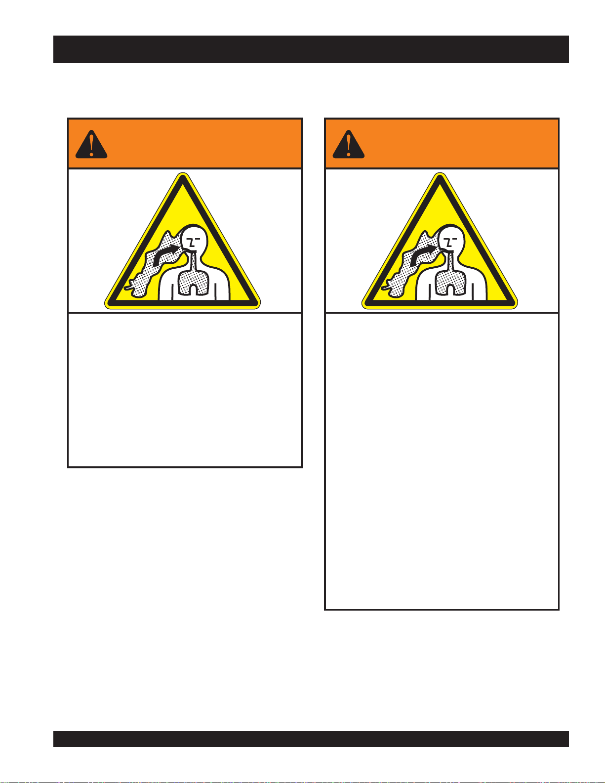
Grinding/cutting/drilling of masonry, concrete, metal and
other materials can generate dust, mists and fumes
containing chemicals known to cause serious or fatal
injury or illness, such as respiratory disease, cancer,
birth defects or other reproductive harm. If you are
unfamiliar with the risks associated with the particular
process and/or material being cut or the composition of
the tool being used, review the material safety data
sheet and/or consult your employer, the material
manufacturer/supplier, governmental agencies such as
OSHA and NIOSH and other sources on hazardous
materials. California and some other authorities, for
instance, have published lists of substances known to
cause cancer, reproductive toxicity, or other harmful
effects.
Control dust, mist and fumes at the source where
possible. In this regard use good work practices and
follow the recommendations of the manufacturers or
suppliers, OSHA/NIOSH, and occupational and trade
associations. Water should be used for dust
suppression when wet cutting is feasible. When the
hazards from inhalation of dust, mists and fumes cannot
be eliminated, the operator and any bystanders should
always wear a respirator approved by NIOSH/MSHA for
the materials being used.
WARNING
SILICOSISWARNING RESPIRATORY HAZARDS
Page 3

STR46SPV GH — TABLE OF CONTENTS
STOW — STR46SPVGH RIDE-ON
POWER TROWEL
(VANGUARD ENGINE)
Table of Contents ...................................................... 3
Training Checklist ...................................................... 4
Daily Pre-Operation Checklist ................................... 5
Safety Message Alert Symbols .............................. 6-7
Rules For Safe Operation .................................... 8-11
Dimensions ............................................................. 12
Specifications .......................................................... 13
General Information ................................................ 14
Controls and Indicators ...................................... 15-16
Engine Components ............................................... 17
Setup ....................................................................... 18
Inspection ................................................................ 19
Operation ........................................................... 20-21
Maintenance ...................................................... 22-36
Decals ..................................................................... 37
Troubleshooting ................................................. 38-39
Terms And Conditions of Sale-Parts ....................... 40
Specifications and
NOTE
STR46SPVGH • RIDE-ON POWER TROWEL — OPERATION MANUAL — REV. #0 (07/17/08) — PAGE 3
part numbers are
subject to change
without notice.
Page 4

STR46SPV GH — TRAINING CHECKLIST
TRAINING CHECKLIST
This checklist lists some of the minimum requirements for machine operation. Please feel free to make copies for daily use. Use this
checklist when training a new operator or use as a review for more experienced operators.
TSILKCEHCGNINIART
.ON NOITPIRCSED ?KO ETAD
1 .yletelpmoclaunaMs’rotarepOdaeR
2 .slevellioxobraegdnaenignefognikcehc,stnenopmocfonoitacol,tuoyalenihcaM
3 .erudecorpgnileufer,metsysleuF
4 .)deppiuqefi(sthgildnayarpsfonoitarepO
5 .)gninnurtonenihcam(slortnocfonoitarepO
6 .noitarepohctiwSpotSytefaStaes,slortnocytefaS
7 .serudecorppotsycnegremE
8 .enihcamfoputratS
9 .revohagniniatniaM
01 gnirevuenaM
11 gnihctiP
21 .srewotneewtebhctipedalbgnihctaM
31 .seuqinhcetgnihsinifetercnoC
41 .enihcamfonwodtuhS
51 .punaelcenihcaM
61 .)spooltfil(enihcamfognitfiL
71 .egarotsdnatropsnartenihcaM
Operator _________________________________________ Trainee __________________________________________
COMMENTS:
PAGE 4 — HHN 31V
STR46SPVGH • RIDE-ON POWER TROWEL — OPERATION MANUAL — REV. #0 (07/17/08) — PAGE 4
Page 5

DAILY PRE-OPERATION CHECKLIST
DAILY PRE-OPERATION CHECKLIST
TSILKCEHCNOITAREPO-ERPYLIAD
1
2
3 .leveLtnalooCrotaidaR
4 sedalBfonoitidnoC
5 .noitarepOhctiPedalB
6 .noitarepOhctiwSpotS-ytefaS
7 .noitarepOlortnoCgnireetS
8 .stleBfonoitidnoC
COMMENTS:
diulFxobraeGleveL
.leveLliOenignE
.
.
STR46SPVGH • RIDE-ON POWER TROWEL — OPERATION MANUAL — REV. #0 (07/17/08) — PAGE 5
Page 6

STR46SPV GH — SAFETY MESSAGE ALER T SYMBOLS
FOR YOUR SAFETY AND THE SAFETY OF OTHERS!
Safety precautions should be followed at all times when
operating this equipment. Failure to read, understand and
comply with the Safety Messages and Operating Instructions
could result in injury to yourself and others.
This Operation Manual has been
developed to provide instructions for the
safe and efficient operation of the STR 46SPVGH Ride-On Trowel. For engine
maintenance information, please refer to the
engine manufacturer's instructions for data
relative to its safe operation.
Before using this Ride-On Trowel, ensure that the operating
individual has read, understands, and complies with all
instructions in this manual.
HAZARD SYMBOLS
SAFETY MESSAGE ALERT SYMBOLS
The three (3) Safety Messages shown below will inform you
about potential hazards that could injure you or others. The
Safety Messages specifically address the level of exposure to
the operator, and are preceded by one of three words:
DANGER, WARNING, or CAUTION.
Lethal Exhaust Gases
Engine exhaust gases contain harmful toxins
and will displace oxygen when running in an
enclosed or confined space. NEVER operate
this equipment in a confined area or enclosed
structure that does not provide ample free
flow air.
Explosive Fuel
Engine fuel is flammable, and its vapors can
cause an explosion if ignited. DO NOT start
the engine near spilled fuel or combustible
fluids. DO NOT fill the fuel tank while the
engine is running or hot. DO NOT overfill
tank, since spilled fuel could ignite if it comes
into contact with hot engine parts or sparks
from the ignition system. Store fuel in
approved containers, in well-ventilated areas
and away from sparks and flames. NEVER
use fuel as a cleaning agent.
Burn Hazards
DANGERDANGER
DANGER
DANGERDANGER
You WILL be
if you DO NOT follow these directions.
WARNINGWARNING
WARNING
WARNINGWARNING
You CAN be KILLED or
you DO NOT follow these directions.
CAUTICAUTI
CAUTION
CAUTICAUTI
You CAN be
these directions.
Potential hazards associated with trowel operation will be
referenced with Hazard Symbols which appear throughout this
manual, and will be referenced in conjunction with Safety
Message Alert Symbols.
KILLED
INJURED
if you DO NOT follow
or
SERIOUSLY INJURED
SERIOUSLY INJURED
if
Engine components can generate extreme heat.
To prevent burns, DO NOT touch these areas
while the engine is running or immediately after
operations. NEVER operate the engine with
heat shields or heat guards removed.
Rotating Parts
NEVER operate equipment with covers or
guards removed. Keep
and
clothing
prevent injury.
fingers, hands, hair
away from all moving parts to
PAGE 6 — HHN 31V
STR46SPVGH • RIDE-ON POWER TROWEL — OPERATION MANUAL — REV. #0 (07/17/08) — PAGE 6
Page 7

STR46SPV GH — SAFETY MESSAGE ALER T SYMBOLS
Accidental Starting Respiratory Hazard
ALWAYS place the ON/OFF switch in the
OFF position. Disconnect and ground spark
plug lead and disconnect negative battery
cable from battery before servicing.
Over Speed Conditions
NEVER tamper with the factory settings of the
engine governor or settings. Personal injury
and damage to the engine or equipment can
result if operating in speed ranges above
maximum allowable.
Accidental starts can
cause severe injury or
death.
ALWAYS wear approved respiratory protection.
Sight and Hearing hazard
ALWAYS wear approved eye and
hearing protection.
Equipment Damage Messages
Other important messages are provided throughout this manual
to help prevent damage to your trowel, other property, or the
surrounding environment.
CAUTICAUTI
CAUTION
CAUTICAUTI
This Ride-On Trowel, other property, or the
surrounding environment could be damaged
if you do not follow instructions.
STR46SPVGH • RIDE-ON POWER TROWEL — OPERATION MANUAL — REV. #0 (07/17/08) — PAGE 7
Page 8

STR46SPV GH — RULES FOR SAFE OPERA TION
RULES FOR SAFE OPERA TION
WARNINGWARNING
WARNING
WARNINGWARNING
Failure to follow instructions in this manual may lead to serious
injury or even death! This equipment is to be operated by
trained and qualified personnel only! This equipment is for
industrial use only.
■
NEVER operate this equipment when not feeling well due to
fatigue, illness or taking medicine.
■
NEVER operate the trowel under the influence or drugs or
alcohol.
■
Replace nameplate, operation and safety decals when they
become difficult to read.
■
ALWAYS check the trowel for loosened hardware such as
nuts and bolts before starting.
The following safety guidelines should always be used when
operating the Ride-On Trowel.
SAFETY
■
DO NOT operate or service this equipment
before you read, understand, and comply
with all safety messages in this manual.
The manual must be kept available and
accessible to the operator.
■
This equipment should not be operated by persons under the
minimum statutory age limit.
■
NEVER use this machine for any purpose other than those
described in this manual.
■
NEVER operate the trowel without proper protective clothing,
shatterproof glasses, steel-toed boots and other protective
devices required for the job.
■
NEVER touch the hot exhaust manifold, muffler
or cylinder. Allow these parts to cool before
servicing the trowel. Contact with
components can cause serious burns.
■
The engine of this trowel requires an adequate free flow of
cooling air. NEVER operate the trowel in any enclosed or
■
ALWAYS refuel in a well-ventilated area, away from sparks
and open flames.
■
Topping-off to filler port is dangerous, as it tends to spill fuel.
■
NEVER use fuel as a cleaning agent.
hot
narrow area where free flow of
the air is restricted. If the air flow
is restricted it will cause serious
damage to the engine and may
cause injury to people.
Remember the engine can give
off harmful toxins and will
displace oxygen.
■
■
NEVER use accessories or attachments which are not
recommended by Multiquip for this equipment. Damage to
the equipment and/or injury to user may result.
■
Manufacturer does not assume responsibility for any accident
due to equipment modifications. Unauthorized equipment
modification will void all warranties. Any modification which
could lead to a change in the original characteristics of the
machine should be made only by the manufacturer who shall
confirm that the machine is in conformity with appropriate
safety regulations.
PAGE 8 — HHN 31V
STR46SPVGH • RIDE-ON POWER TROWEL — OPERATION MANUAL — REV. #0 (07/17/08) — PAGE 8
■
■
AL WAYS use extreme caution when working with flammable
liquids. When refueling, STOP the engine. Allow the engine
to cool before adding fuel or performing service and
maintenance functions.
NEVER operate the trowel in an
explosive atmosphere where fumes
are present, or near combustible
materials. An explosion or fire could
result in severe
death.
NEVER
Fire or explosion could result from
vapors
smoke
, or if fuel is spilled on a
bodily harm or even
around or near the machine.
fuel
hot!
engine.
Page 9

STR46SPV GH — RULES FOR SAFE OPERA TION
■
NEVER run engine without air filter. Severe engine damage
may occur. Service air filter frequently to prevent carburetor
malfunction.
■
NEVER place your
while starting or operating this equipment.
■
AVOID wearing jewelry or loose fitting clothing that may snag
on the controls or moving parts as this can cause a serious
injury.
■
ALWAYS keep clear of
operating the trowel.
■
Moving Parts – Shut down the engine before performing
service or maintenance functions. Contact with moving parts
can cause serious injury.
■
ALWAYS check to make sure that the operating area is clear
before starting the engine.
■
NEVER leave the machine
■
ALWAYS be sure the operator is familiar with proper safety
precautions and operations techniques before using trowel.
feet
or
rotating
hands
inside the guard rings
or
moving parts
unattended
while running.
while
Lifting the Ride-On Trowel
This ride-on trowel is very
around. Use proper heavy lifting procedures and DO NOT
attempt to lift the ride-on trowel by the guard rings.
DANGERDANGER
DANGER
DANGERDANGER
Pay close attention to ventilation when
operating the trowel in confined spaces
such as tunnels, buildings or similar areas.
The engine exhaust contains harmful
elements. Ensure proper air flow to move
engine exhaust away from the operator.
CAUTIONCAUTION
CAUTION
CAUTIONCAUTION
heavy
and awkward to move
■
ALWAYS keep the work area well organized.
■
ALWAYS clear the work area of any debris, tools, etc. that
would constitute a hazard while the trowel is in operation.
WARNINGWARNING
WARNING
WARNINGWARNING
ALWAYS check to make sure that the operating area is
clear before starting the engine.
■
No one other than the operator is to be in the working area
when the trowel is in operation.
■
NEVER allow passengers or riders on the trowel during
operation.
■
Always observe all applicable compulsory regulations
relevant to environmental protection, especially, fuel storage,
the handling of hazardous substances, and the wearing of
protective clothing and equipment. Instruct the user as
necessary, or, as the user, request this information and
training.
■
ALWAYS store equipment properly when it is not being used.
Equipment should be stored in a clean, dry location out of the
reach of children.
The STR46SPVGH Ride-On Power Trowel is designed to be
moved and handled several ways.
The easiest way to lift the trowel is to utilize the lift loops that are
welded to the frame. These lift loops are located to the left and
right sides of the operator’s seat.
A strap or chain can be attached to these lift loops, allowing a
forklift or crane to lift the trowel up onto and off of a slab of concrete.
The strap or chain should have a minimum 2,000 pounds (1000kg) lifting capacity and the lifting gear must be capable of lifting
at least this amount.
NEVER stand under or allow anyone
else to stand under the trowel while it
is being lifted.
DANGERDANGER
DANGER
DANGERDANGER
STR46SPVGH • RIDE-ON POWER TROWEL — OPERATION MANUAL — REV. #0 (07/17/08) — PAGE 9
Page 10

STR46SPV GH — RULES FOR SAFE OPERA TION
■
Transporting
■
ALWAYS shutdown engine before transporting.
■
Tighten fuel tank cap securely and close fuel cock to prevent
fuel from spilling.
■
Drain fuel when transporting trowel for long distances or over
bad roads.
■
When placing the trowel on a truck-bed for transport,
tie-down the trowel.
■
If the trowel is being transported via a trailer, make sure the
trailer complies with all local and state safety transportation
laws. Refer to the following "
for basic towing techniques.
Towing Safety Precautions
CAUTIONCAUTION
CAUTION
CAUTIONCAUTION
Conform to
Towing Regulations
roads.
To reduce the possibility of an accident while transporting the
trowel on public roads, always make sure the trailer that supports
the trowel and the towing vehicle are in good operating condition
and both units are mechanically sound.
The following list of suggestions should be used when towing
your trowel:
■
Make sure the hitch and coupling of the towing vehicle are
rated equal to, or greater than the trailer "gross vehicle weight
rating" (GVWR) of 6,000 lbs.
■
ALWAYS inspect the hitch and coupling for wear. NEVER
tow a trailer with defective hitches, couplings, chains, etc.
■
Check the tire air pressure on both towing vehicle and trailer.
Department of Transportation (DOT) Safety
before transporting trowel on public
T o wing Safety Precautions"
T railer tires should be inflated to 50 psi cold
the tire tread wear on both vehicles.
■
ALWAYS make sure the trailer is equipped with "Safety
Chains ".
■
AL WAYS attach trailer's safety chains to towing vehicle
properly.
■
ALWAYS make sure the vehicle and trailer directional,
backup, brake, and trailer lights are connected and working.
■
DO NOT exceed the recommended highway speed when
towing.
STR46SPVGH • RIDE-ON POWER TROWEL — OPERATION MANUAL — REV. #0 (07/17/08) — PAGE 10
always
. Also check
PAGE 10 — HHN 31V
Use chock-blocks underneath each wheel when parked to
prevent trailer from rolling.
■
Use the trailer's swivel jack to adjust the trailer height to a
level position while parked.
■
Avoid sudden stops and starts. This can cause the trailer to
skid or jack-knife. Smooth, gradual starts and stops will
improve towing.
■
Avoid sharp turns.
■
Trailer should be adjusted to a level position at all times
when towing.
■
Raise and lock trailer wheel stand in the "UP" position when
transporting.
■
DOT requirements include the following:
Connect and test electric brake operation.
Secure portable power cables in cable tray with tie wraps.
Battery
The battery contains acid that can cause injury to the eyes and
skin. To avoid eye irritation,
shielding. Use well insulated gloves when handling the battery.
Use the following guidelines when handling the battery.
■
DO NOT drop the battery. Any impact to
the battery may cause it to explode.
■
DO NOT expose the battery to open flames,
sparks, lit cigarettes etc. The battery
contains combustible gases and liquids. If
these gases and liquids come in contact
with a flame or spark an explosion can occur.
■
ALWAYS keep the battery charged. If the
battery is not charged a buildup of combustible gas will occur.
■
ALWAYS keep battery cables in good working condition.
Repair or replace all worn cables.
■
ALWAYS disconnect the
performing service on the trowel.
■
ALWAYS recharge the battery in a vented air environment
to avoid risk of a dangerous concentration of combustible
gases.
■
In case the battery electrolyte liquid, (dilute sulfuric acid),
comes in contact with
immediately with plenty of water.
■
In case the battery electrolyte liquid, (dilute sulfuric acid),
comes in contact with your
with plenty of water, then contact the nearest doctor or hospital
and seek medical attention.
always
wear safety glasses or face
negative battery terminal
clothing or skin
eyes
, rinse skin or clothing
, rinse eyes immediately
before
Page 11
STR46SPV GH — RULES FOR SAFE OPERA TION
■
Replace batteries that have cracked or broken cases or
batteries that are otherwise leaking electrolyte.
■
A good practice is to isolate the machine when removing the
battery.
■
Always replace with battery of equivalent type and rating.
Never replace with a non-rechargeable battery.
■
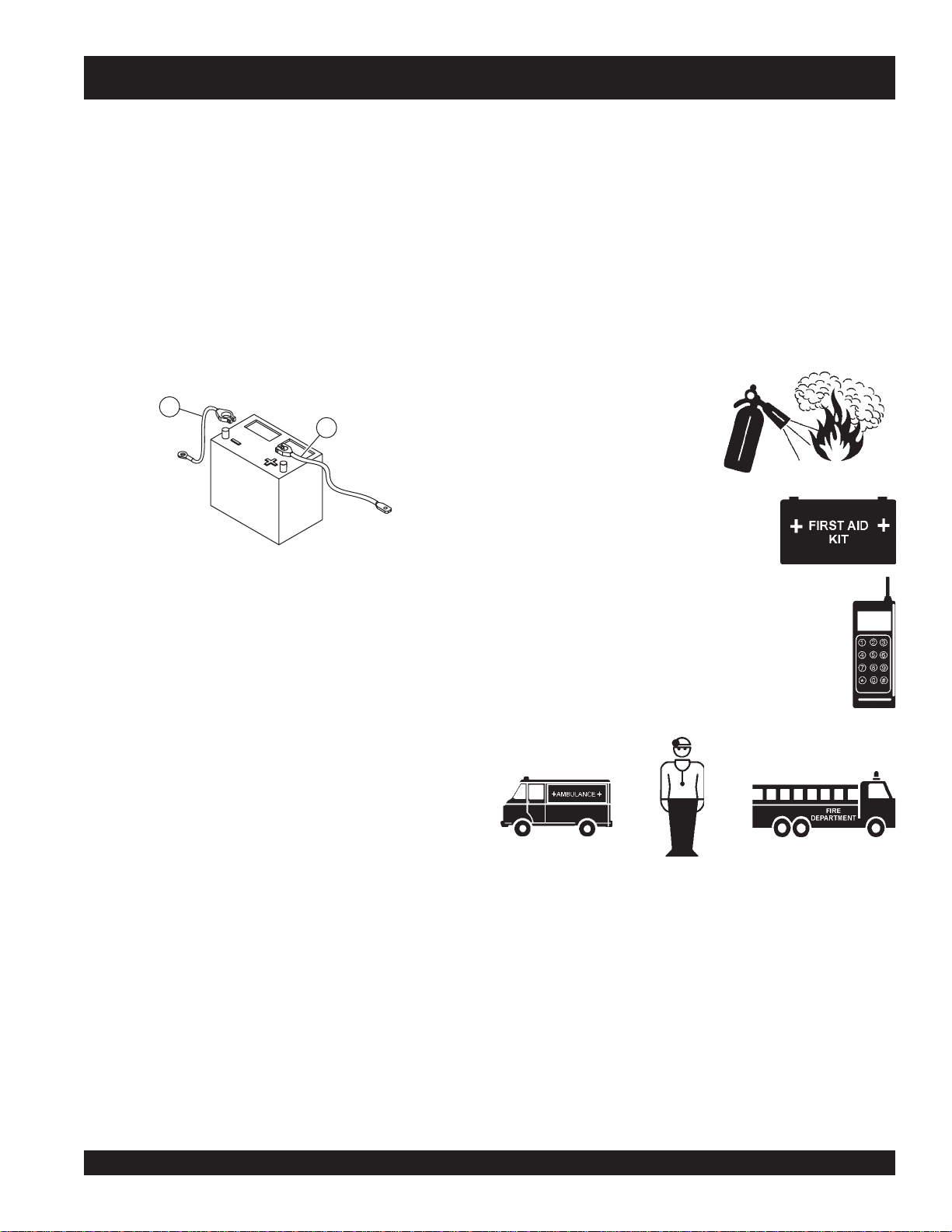
Orientation of the Battery
The positive cable , normally red, is associated with the "+" symbol
on the battery. The negative cable, normally black, is associated
with the "
to the positive terminal on the battery and the negative cable is
connected to the negative terminal.
-" symbol on the battery. The positive cable is connected
1
2
■
DON'T POLLUTE! Waste oils and other chemicals must be
disposed of in a manner consistent with local and state
environmental protection regulations. Examples of potentially
hazardous waste are used motor oil, fuel and fuel filters.
■
DO NOT use plastic food containers to dispose of hazardous
waste.
■
DO NOT pour waste, oil or fuel directly onto the ground,
down a drain or into any water source.
Emergencies
■
ALWAYS know the location of
the nearest
■
ALWAYS know the location of the
nearest
fire extinguisher
first aid kit
.
.
1. Negative Cable (BLACK)
2. Positive Cable (RED)
■
Always dispose of battery properly. Bring to appropriate facility
for lead reclamation. These facilities can generally be found
in the local phone listings under "Recycling Services".
Maintenance Safety
■
AL W AYS shut down the engine and disconnect battery before
performing service or maintenance functions. Contact with
moving parts can cause serious injury.
■
Securely support any trowel components that must be raised.
■
NEVER lubricate components or attempt service on a running
trowel.
■
ALWAYS allow the trowel a proper amount of time to cool
before servicing.
■
Keep the trowel in proper running condition.
■
Make sure that there is no buildup of concrete, grease, oil or
debris on the machine.
■
Know the phone numbers of the nearest
ambulance, doctor
that a phone or radio is readily available at the
jobsite. If this is not possible, know the location of
the nearest phone. This information will be
invaluable in the event of an emergency.
and
fire department
. Ensure
■
Fix damage to the trowel immediately and always replace
broken parts.
STR46SPVGH • RIDE-ON POWER TROWEL — OPERATION MANUAL — REV. #0 (07/17/08) — PAGE 11
Page 12

STR46SPV GH — SPECIFICA TIONS
NOTE:
B-WIDTH
46
R
T
S
A-LENGTH
Figure 2. STR46SPVGH
Dimension Specifications
RETEMARAPNOITACIFICEPS )DRAUGNAV(HGVPS64RTS
)mc(.ni–htgneL–A )4.642(0.79
)mc(.ni–htdiW–B )721(0.05
1
)mc(.ni–thgieH–C
gnitarepO).sgk(.sbl–thgieW )774(240,1
gnippihS).sgk(.sbl–thgieW )555(422,1
2
ABd–erusserPdnuoS
2
s/tf–noitarbiV
3
s/m(2)
phbtuptuoxam–enignE 13
)sretil(snollag–knaTleuF )91(5
MPR–rotoR 061ot06
)mc(.ni–htdiWhtaP )132(19
liOnoitacirbuLxobraeG PE5RG022OSI
yticapaCliOxoBraeG )sretil62.4(.zo441
)daoLlluF(noitpmusnoCleuF rh-phb/bl45.0
yticapaCrotaidaR )sretil97.3(.lag0.1
C-HEIGHT
snoitacificepSHGVPS64RTS.1elbaT s
1
)711(0.64
59
)5.2(0.8<
1. This value does not include seat height. To obtain total
height (seat ) add 4 inches (10.2 cm.).
2. Sound pressure is "A" weighted . Measured at the operators
ear position while the ride-on trowel is operating at full
throttle on concrete in a manner most often experienced in
normal
“
” circumstances. Sound pressure may vary
depending upon the condition of the concrete. Hearing
3. The vibration level indicated is the maximum RMS (Root
Mean Square) value obtained at the handle grip while
operating the ride-on trowel on curing concrete in a
manner most often experienced in “
circumstances. Values were obtained from all three axes
of motion. The values shown represent the maximum RMS
value from these measurements.
protection is always recommended.
PAGE 12 — HHN 31V
STR46SPVGH • RIDE-ON POWER TROWEL — OPERATION MANUAL — REV. #0 (07/17/08) — PAGE 12
normal
”
Page 13

STR46SPV GH— SPECIFICA TIONS (ENGINE)
snoitacificepSenignEHGVPS64RTS.2elbaT
ledoM
epyT
srednilyC3
tnemecalpsiDnotsiP)cc259(.ni.uc1.85
ekortSdnaeroB )mm87xmm27(.ni70.3x.ni38.2
tuptuO.xaM)wK53.52(mpr0063/phb13
euqroT.xaMmpr0032ta)gK4.62(tf-fbl3.85
metsySgnilooC noitalucricdecrof,delooc-diuqil
yticapaCliOenignE
metsySgnitacirbuL retliFrepaPwolF-lluFhtiwebuLerusserP
liOnoitacirbuLenignErehgihrossalcESIPA
knaTleuF)sretil9.81(.lag5
HGVPS64RTS
HGVPS64RTS
)sretil3(.tq2.3
DRAUGNAVNOTTARTS&SGGIRB
draugnaV,nottartS&sggirB
)tnemecalperretliflio/wsretil3.3(.tq5.3
yticapaCdnuopmoCraeGxobraeGlacileH
leuF gnitarenatco58fomuminim-leuFenilosaG
metsySgnitratSretratScirtcelE
thgieWyrDenignE)gK98(.sbl691
)HxWxL(snoisnemiD
)sretil62.4(.zo441
PE5RGAMGAO22OSI
.ni47.91x.ni28.71x.ni72.71
)mm4.105xmm5.744xmm7.834(
STR46SPVGH • RIDE-ON POWER TROWEL — OPERATION MANUAL — REV. #0 (07/17/08) — PAGE 13
Page 14

STR46SPV GH — GENERAL INFORMA TION
STR46SPVGH Ride-On P ower T rowel F amiliarization
The STR46SPVGH Ride-On Power Trowel is designed for the
floating and finishing of concrete slabs.
Take a walk around your trowel. Take notice of all the major
components like the engine, blades, air cleaner, fuel system,
fuel shut-off valve, ignition switch etc. Ensure engine and gearbox
lubricant levels are within proper operating range.
Read all the safety instructions carefully. Safety instructions will
be found throughout this manual and on the machine. Keep all
safety information in good, readable condition. Operators should
be well trained on the operation and maintenance of the trowel.
Look at the operator control levers. Grasp the control levers and
move them around a bit. Observe how moving the control levers
cause the gearboxes and frame to move.
Notice the foot pedal which controls the engine and blade speed.
Also take a look at the main driveline of the trowel. Take note
and reference how the belts look, this is the way the belts should
look when adjusted properly.
Before using your trowel, test it on a flat watered down section of
finished concrete. This trial test run will increase your confidence
in using the trowel and at the same time it will familiarize you
with the trowel’s controls and indicators. In addition you will
understand how the trowel will handle under actual conditions.
Engine
This Trowel is equipped with a liquid cooled 31 HP Vanguard
gasoline engine. Refer to the engine owner’s manual for specific
instructions regarding engine operation. This manual is included
with the trowel at the time of shipping. Please contact your nearest
Multiquip Dealer should a replacement manual be required.
Gearboxes
The STR46SPVGH Ride-On Power Trowel consist of two
separate gearbox assemblies that are enclosed in rugged cast
aluminum gear cases.
The gearbox casing holds 50% more oil capacity than
competitors, which allows more lubrication to be provided to
critical points.
Steering
Dual control levers located in front of the operator's seat are
provided for steering this trowel. The control levers are linked to
two spring loaded cylinders.
Push the left control lever forward and pull the right control lever
backward and the trowel will rotate clockwise on approximately
a center axis. Pull the left control lever backward and push the
right control lever forward and the trowel will rotate
counterclockwise. See Table 3 on page 21 for a complete
description on the control levers directional positioning.
Constant Velocity Joints (CV -Joints)
Constant velocity joints insure the efficient transfer of power to
the drive shaft and maintain the timing of the gearboxes without
any chance of slippage.
Training
For training, please use the “TRAINING CHECKLIST” located
in the front of this manual (Page 4). This checklist is not intended
to be a substitute for proper training but will provide an outline
for an experienced operator to provide training to a new operator.
Blades
The blades of the STR46SPVGH Ride-On Power Trowel finish
the concrete as they are swirled around the surface. Blades are
classified as combination (10 or 8 inches wide) and finish (6
inches wide). The STR46SPVGH Ride-On Power Trowels are
equipped with five blades, per rotor equally spaced in a radial
pattern and attached to a vertical rotating shaft by means of a
spider assembly.
Figures 3 and 4 show the location of the controls, indicators and
general maintenance parts. Each control may perform more than
one function. The functions of each control or indicator is on
pages 15 and 16.
PAGE 14 — HHN 31V
STR46SPVGH • RIDE-ON POWER TROWEL — OPERATION MANUAL — REV. #0 (07/17/08) — PAGE 14
Page 15

STR46SPV GH — CONTROLS AND INDICA T ORS
1. Seat – Provides comfortable position for operation of the
trowel. Engine will not start unless operator is seated. Seat
is adjustable, fore and aft for operator comfort.
2. Steering Control Lever (right side) -Allows the unit to
move in either a forward, reverse left or right direction.
3. Radiator/Filler Cap – Holds coolant or water necessary to
keep engine at a safe operating temperature. Remove this
cap to add water or antifreeze. DO NOT revove this cap
when the engine is warm.
4. Pitch Control (Right) – Adjusts the blade pitch for right
side of the trowel.
5. Pitch Control (Left) – Adjusts the blade pitch for left side
of the trowel.
6. Steering Control Lever (left side) -Allows the unit to move
in either a forward, reverse left or right direction.
7. Light Switch – When activated, turns on four halogen
lights. Lights offer better visibility when working indoors.
8. Ignition Switch – With key inserted turn clockwise to
start engine.
9. Oil Indicator Light - Lights red when oil pressure is low.
10. Water Indicator Light - Lights red when water temperature
is high.
11. Charge Indicator - Lights red when electrical system is
not charging properly.
12. Hour Meter - Indicates number of hours the key switch is
in the "ON" position.
13. Choke Control Lever - In cold weather pull this lever
forward about half way to start engine. After engine warms
push knob all the way in.
14. Fuel Filler Cap - Remove this cap to add fuel.
15. Fuel T ank - Holds 5 gallons of fuel.
16. Spare Belt Carrier - Contains a spare belt. Belt is used on
the drive pulley.
17. Left Foot Riser – Operator foot rest pedal.
18. EZ -Mover Boss – Front-side insertion point for EZ Mover.
Used when the transporting of the trowel is required.
19. Right Foot Pedal – Controls blade speed. Slow blade
speed is accomplished by slightly depressing the foot pedal.
Maximum blade speed is accomplished by fully depressing
the foot pedal.
10
9
11
1
2
5
4
CHG
WATER
OIL
6
14
15
3
46
STR
16
17
12
18
8
18
7
19
Figure 3. STR46SPVGH Controls and Indicators (Front)
STR46SPVGH • RIDE-ON POWER TROWEL — OPERATION MANUAL — REV. #0 (07/17/08) — PAGE 15
Page 16

STR46SPV GH — CONTROLS AND INDICA T ORS
20. Oil Sight Glass - Indicates the level of the hydraulic oil in
the gear box.
21. EZ- Mover Boss – Front -side insertion point for EZ Mover.
Used when the transporting of the trowel is required.
22. Lift Loops – Located on both the left and right sides of the
main frame. Used when the trowel must be lifted onto a
concrete slab.
23. Lights – Four 12 volt halogen lights are provided with this
unit.
24. Right-Side Spider – Consists (basic) of trowel arms,
blades, wear plate, and thrust collar etc.
25. Left-Side Spider – Consists (basic) of trowel arms, blades,
wear plate, and thrust collar etc.
26. Belt Guard – Encloses drive belt used in conjunction with
clutch.
27. Overflow Bottle - Supplies coolant to the radiator when
28. Engine Air Filter – Prevents dirt and other debris from
29. Engine Dip Stick – Indicates engine oil level. Add oil as
30. Oil Filter – Provides oil filtering for the engine.
31. Battery – Provides +12V DC power to the electrical
radiator coolant level is low. Fill to indicated level as shown
on bottle.
entering the fuel system. Lift locking latch on air filter
cannister to gain access to filter element.
required.
system
25
26
20
21
23
28
31
22
29
30
21
27
20
22
24
Figure 4. STR46SPVGH Controls and Indicators (Rear)
PAGE 16 — HHN 31V
STR46SPVGH • RIDE-ON POWER TROWEL — OPERATION MANUAL — REV. #0 (07/17/08) — PAGE 16
Page 17

STR46SPV GH — ENGINE
Figure 5. Gasoline Engine Controls and Components
INITIAL SERVICING
The gasoline engine (Figure 5) must be checked for proper
lubrication and filled with fuel prior to operation. Refer to the
manufacturer's engine manual for instructions & details of
operation and servicing. The engine shown above is a Briggs &
Stratton Vanguard Gasoline engine. Operation for other types of
engines may vary somewhat.
1. Thermostat – Regulates the temperature of the engine
coolant.
2. Oil Filler Cap – Remove to add engine oil.
WARNINGWARNING
WARNING
WARNINGWARNING
Engine components can generate extreme
heat. To prevent burns, DO NOT touch these
areas while the engine is running or
immediately after operating. NEVER operate
the engine with the muffler removed.
3. Ignition Coil – Provides spark to the ignition system.
4. Starter – Starts engine when ignition key is rotated to the
"ON" position.
6. Alternator – Maintains charge of battery.
7. Spark Plug – Provides spark to the combustion chamber.
Clean spark plugs once a week. Set spark plug gap
according to engine manufacturer's specifications.
8. Coolant T emperature Sending Unit – Provides coolant/
water temperature information to the water temperature
indicator. If temperature is too high will cause the
temperature indicator to be ON.
9. Governor Lever – Controls engine speed.
10. Oil Drain – Remove to drain crankcase oil.
11. Oil Filter – Spin-on type, filters oil for contaminants.
12. Oil Dip Stick – Remove to check amount and condition of
oil in crankcase.
13. Oil Pressure Sending Unit – Provides oil pressure
information to the oil pressure indicator. If oil pressure is
too low will cause the oil pressure indicator to be ON.
14. Carburetor – Provides a precise mixture of air and fuel to
run the engine.
15. Air Filter (not shown) – Prevents dirt and other debris
from entering the fuel system. Unsnap air filter cover to
gain access to filter element.
5. Oil Pan – Reservoir for engine oil.
STR46SPVGH • RIDE-ON POWER TROWEL — OPERATION MANUAL — REV. #0 (07/17/08) — PAGE 17
Page 18

STR46SPV GH — NEW MACHINE SETUP INSTRUCTIONS
T ro wel Pre-Set-Up Instructions
The purpose of this section is to assist the user in setting up a
NEW
trowel. If the trowel is already assembled, (seats, handles,
knobs and battery), this section can be skipped.
The new ride-on trowel cannot be put
into service until the pre-setup
NOTE
Before packaging and shipping this Ride-On Power Trowel was
run and tested at the factory. If there are problems, please let us
know.
Control Handle Assembly
The steering control handles are not attached to the trowel's two
lower handles at the time of shipment. To attach the steering
control handles to the lower handle assemblies perform the
following:
1. Remove the bolts from the plastic bag tied to the control
towers.
2. Remove all protective wrapping and straps from the control
handles.
installation instructions are
completed. These pre-setup
instructions only need to be performed
at the time of unpacking a
trowel.
NEW
Seat Assembly
The seat is not installed on the trowel for shipping purposes.
To attach the seat perform the following:
NOTE
1. Remove the seat from the protective wrapping.
2. Remove the bolts on the bottom of the seat, and place seat
on the seat mounting plate, then insert the bolts through
the holes or slots on the seat mounting plate and tighten.
Battery Setup
This trowel was shipped with a wet charged battery. This battery
may need to be charged for a brief period of time as per the
manufacturer instructions.
Use all safety precautions specified by the battery
manufacturer when working with the battery. See further
specific safety information on page 10 & 11 of this manual.
CAUTIONCAUTION
CAUTION
CAUTIONCAUTION
H-series trowels have a seat that is
mounted on tracks, similar to an
automobile seat. This seat can be
adjusted fore and aft via the control
lever under the front of the seat.
3. Slip the top (loose) control handle piece into the base of
the corresponding handle, making sure to line up the holes.
4. Install the bolt through the lined up holes and tighten the
acorn nut onto the threaded end.
Models equipped with adjustable
NOTE
5. Pay close attention to any wires that may be inside the
control handles. DO NOT pinch or cut any wires during
installation.
6. Remove the two knobs from the plastic bag for the pitch
control tower cranks and install the knobs onto the tower
crank levers.
STR46SPVGH • RIDE-ON POWER TROWEL — OPERATION MANUAL — REV. #0 (07/17/08) — PAGE 18
height handles are adjusted by
placing the bolt through the set of
holes that bring the handles to a
height most comfortable for the
operator.
PAGE 18 — HHN 31V
To install the battery on the trowel, make sure that the battery is
well seated in the battery box. The positive cable , normally red,
is associated with the "+" symbol on the battery. The negative
cable, normally black, is associated with the "
battery. Connect the positive cable to the positive terminal on
the battery first, then connect the negative cable to the negative
terminal. Close the plastic battery box cover and secure the
battery box.
-" symbol on the
1
2
1. Negative Cable (BLACK)
2. Positive Cable (RED)
Figure 6. Battery Cable Orientation
Page 19

STR46SPV GH — INITIAL ST ART-UP
INITIAL ST ART UP
This section is intended to assist the operator with the initial
start-up of the STR46SPVGH trowel. It is extremely important
that this section be read carefully before attempting to use the
trowel in the field.
DO NOT use your trowel until this section is thoroughly
understood.
CAUTIONCAUTION
CAUTION
CAUTIONCAUTION
Failure to understand the operation of the STR46SPVGH
Trowel could result in severe damage to the trowels or
personal injury.
See Figures 3 and 4 (Pages 15 and 16) for the location of
any control or indicator referenced in this manual.
Figure 8. Gearbox Oil Plugs/Sight Glass
Fuel
Determine if the engine fuel is low (Figure 9). If fuel level is low,
remove the fuel filler cap and fill with appropriate engine fuel.
Engine Oil Level
The STR46SPVGH uses gasoline fuel.
1. Pull the engine oil dipstick from its holder.
2. Determine if engine oil is low (Figure 7), add
correct amount of engine oil to bring oil level
to a normal safe level. (See Recommended
Viscosity Grades, Table 4, Page 24).
1
3
1 Fill Plug
2 Drain Plug
3 Sight Glass (Oil Check)
2
1
3
MAX
2
MIN
1 Engine Oil Dipstick
2 Add Engine Oil
3 Safe Operating Oil Level
Figure 7. Engine Oil Dipstick
Handle fuel safely. Motor fuels are highly flammable and
Gearbox Oil Level
can be dangerous if mishandled. DO NOT smoke while
refueling. DO NOT attempt to refuel the ride-on trowel if the
1. Check the gearbox oil level in both gearboxes
engine is hot or running.
by viewing the sight glass at the rear of the
gearbox. See Figure 8.
2. The oil level of the gear box should be at the half-way point
of the sight glass (Figure 8). The gear box oil capacity is
144 oz., (4.26 liters). If additional oil is required, unscrew
the oil fill plug located on top of the gearbox, and refill with
Never store the ride-on trowel with fuel in the tank for any
extended period of time. Always clean up spilled fuel
immediately.
ISO 220 A GMA GR 5 EP oil.
Figure 9. Fuel Fill Cap
CAUTIONCAUTION
CAUTION
CAUTIONCAUTION
CAUTIONCAUTION
CAUTION
CAUTIONCAUTION
Y
L
N
O
L
E
U
F
E
IN
G
N
E
STR46SPVGH • RIDE-ON POWER TROWEL — OPERATION MANUAL — REV. #0 (07/17/08) — PAGE 19
Page 20

STR46SPV GH — OPERA TION
Starting the Engine
1. Place one foot on the trowel's platform, grab ahold of any
part of the frame, lift yourself onto the trowel, then sit down
in the operator's seat.
The STR46SPVGH trowel is
equipped with a safety stop switch
that will not allow the engine to start
NOTE
CAUTIONCAUTION
CAUTION
CAUTIONCAUTION
NEVER disable or disconnect the safety stop switch. It is
provided for the operator's safety and injury may result if it
is disabled, disconnected or improperly maintained.
NOTE
unless an operator is sitting in the
operator’s seat. The weight of an
operator depresses an electrical
switch, which allows the engine to
start.
Using the safey stop switch to stop
the engine after every use will verify
that the switch is working properly.
Remember to turn the key to the “OFF”
position after stopping the machine.
Not doing so may drain the battery.
3. Keep your foot OFF the pedal (right foot pedal). Start the
engine at idle (without touching the foot pedal).
4. Insert the
5. Turn the ignition key clockwise to the (start) position. The
oil, charge,
be ON.
NOTE
ignition key
and
into the ignition switch .
water
indicator lights (Figure 11) should
OIL, and CHARGE indicator lights
come on when ignition switch is in the
ON position, and the engine is NOT
running.
Figure 11. Oil and Charge Indicator Lights
6. Turn ignition key fully clockwise and listen for engine to
start. Once engine has started release ignition key.
7. If the engine fails to start in this manner, consult the engine
owner's manual supplied with the trowel.
8. Test the safety stop switch by standing up briefly. The switch
Figure 10. Blade Speed Control Foot Pedal
2. The right foot pedal (Figure 10) controls blade and engine
speed. The position of the foot pedal determines the blade
speed. Slow blade speed is obtained by slightly depressing
the pedal. Maximum blade speed is obtained by fully
depressing the pedal.
PAGE 20 — HHN 31V
STR46SPVGH • RIDE-ON POWER TROWEL — OPERATION MANUAL — REV. #0 (07/17/08) — PAGE 20
under the seat should cause the engine to stop. If the switch
fails to shut down the engine. Turn off the engine with the
key switch and fix the safety stop switch. See Table 5
(Troubleshooting ) for possible problems.
9. Repeat this section a few times to get fully acquainted with
the engine starting procedure.
Page 21

STR46SPV GH — OPERA TION
Steering
Two control levers located in front of the operator’s seat provide
directional control for the STR46SPVGH trowel. Table 3 illustrates
the various directional positions of the joysticks and their effect
on the ride-on trowel.
NOTE
1. Push both the left and right control levers forward. See
Figure 12.
1
All directional references with respect
to the steering control levers are from
operator’s
the
seat position.
3
5. Try adjusting the pitch of the blades. This can be done with
the ride-on trowel stopped or while the trowel is moving,
whatever feels comfortable. Test the operation of optional
equipment like retardant spray and lights if equipped.
6. Push both the left and right joysticks backward and repeat
steps 3 through 6 while substituting the word reverse for
forward.
Table 3. Control Lever Directional Positioning
3
2
1 Left Control Lever
2 Right Control Lever
3 Forward Direction
Figure 12. Left and Right Control Levers
2. With your right foot quickly depress the right foot pedal
halfway. Notice that the ride-on power trowel begins to move
in a forward direction. Return both joystick controls to their
neutral position to stop forward movement, then remove
your right foot from the right foot pedal.
3. Practice holding the machine in one place as you increase
blade speed. When about 75% of maximum blade speed
has been reached, the blade will be moving at proper
finishing speed. The machine may be difficult to keep in
one place. Trying to keep the ride-on trowel stationary is a
good practice for operation.
4. Practice maneuvering the ride-on trowel using the
information listed in Table 3. Try to practice controlled
motions as if you were finishing a slab of concrete. Practice
edging and covering a large area.
Trowel arms can be damaged by rough handling or by
striking exposed plumbing or forms while in operation.
ALWAYS
to the trowel arms.
CAUTIONCAUTION
CAUTION
CAUTIONCAUTION
look-out for objects which might cause damage
STR46SPVGH • RIDE-ON POWER TROWEL — OPERATION MANUAL — REV. #0 (07/17/08) — PAGE 21
Page 22

STR46SPV GH — MAINTENANCE
MAINTENANCE
When performing maintenance on the trowel or engine, follow
all safety messages and rules for safe operation stated at the
beginning of this manual.
See the engine manual supplied with your machine for appropriate
engine maintenance schedule and troubleshooting guide for
problems.
Y early (500-600 Hours)
1. Check the arm bushings, thrust collar bushings, shaft seals
and belts. Replace if necessary
2. Check pitch control cables for wear.
3. Replace gearbox lubricant.
4. Check and adjust blade speed.
W ARNING
Accidental starts can cause severe injury
or death.
ALWAYS place the ON/OFF switch in the
OFF position.
Disconnect negative battery cable
from battery before servicing.
ALWAYS allow the engine to cool before
servicing. NEVER attempt any
maintenance work on a hot! (muffler,
radiator, etc.) trowel.
MAINTENANCE SCHEDULE
Daily (8-10 Hours)
1. Check the fluid levels in the engine and gearboxes, fill as
necessary.
2. Check V-belt.
Weekly (30-40 Hours)
1. Relube arms, thrust collar and steering links.
2. Replace blades if necessary.
3. Check the engine air filter and change as necessary.
Monthly (100-150 Hours)
1. Remove, clean, reinstall and relube the arms and thrust
collar. Adjust the blade arms.
2. Replace gearbox lubricant after the first 100 hours of
operation. Replace every 500-600 hours.
3. Check drive belt for excessive wear.
4. Replace engine oil and filter as necessary, see engine
manual.
PAGE 22 — HHN 31V
STR46SPVGH • RIDE-ON POWER TROWEL — OPERATION MANUAL — REV. #0 (07/17/08) — PAGE 22
1. Oil Filter
2. Dipstick (engine oil)
3. Flywheel
4. Carburator
5. Air Cleaner
6. Spark Plug
7. Governor Lever
8. Oil Drain Plugs
9. V-Belt
10. Cooling Fan
11. Thermostat
12. Oil Filler Cap
13. Ignition Coil
14. Adjustment Bolt
(V -Belt tensioning)
15. Electric Starter Motor
16. Alternator
Figure 13. Engine Service Areas
Page 23

WARNINGWARNING
WARNING
WARNINGWARNING
STR46SPV GH — MAINTENANCE
1. Unlock the cover clamps (4) and remove cover (3).
2. Remove cartridge (2) from air cleaner body (1).
Certain maintenance operations or machine adjustments
require specialized knowledge and skill. Attempting to
perform maintenance operations or adjustments without
the proper knowledge, skills or training could result in
equipment damage or injury to personnel. If in doubt,
consult your dealer.
Air Cleaner (Daily)
The Vanguard 31 hp engine is equipped with a replaceable,
high-density paper air cleaner element. Check the air cleaner
daily or before starting the engine. Check for and correct heavy
buildup of dirt and debris along with loose or damaged
components, (Figure 14).
1
2
3. Clean cartridge by gently tapping the end with the handle
of a screwdriver. Replace cartridge if very dirty or damaged.
4. Carefully clean out the air cleaner cover.
5. Install cartridge in body.
6. Install cover and lock cover clamps.
NOTE
Changing Engine Oil And Filter
1. Change the engine oil and filter after the first 5 hours of
use, then change oil every 6 months or 1500 hours. Use
engine lubrication oil API SE class or higher.
2. Remove the oil filler cap (Figure 22, Item 6), and fill engine
crankcase with recommended type oil as listed in Table 4.
Fill to the upper limit of dipstick.
Operating the engine with loose or
damaged air cleaner components
could allow unfiltered air into the
engine causing premature wear
and failure.
3
4
1. Air Cleaner Body
2. Cartridge
3. Cover
4. Latches (Cover Clamps)
Figure 14. Air Cleaner Components
3. Crankcase oil capacity with oil filter replacement is 3.5 qts.
(3.3 liters).
Oil Filter (300 Hours)
1. Replace the engine oil filter (Figure 15) every other oil
change or 300 hours. Refer to your engine manual for
specific details to perform this operation.
A
A. Seal
Figure 15. Oil Filter
2. Be sure to coat the
clean engine oil.
STR46SPVGH • RIDE-ON POWER TROWEL — OPERATION MANUAL — REV. #0 (07/17/08) — PAGE 23
seal
(Item A) of the new oil filter with
Page 24

STR46SPV GH — MAINTENANCE
T ab le 4. Recommended Viscosity Grades
30
10W-30, 10W-40, 10W-50
5W-30
-20
F
C
-30
TEMPERATURE RANGE EXPECTED BEFORE NEXT OIL CHANGE
-20
0
-10
32 40 60 80 100
20
10
0
20 30 40
Battery/Charging System
Use Engine Lubrication Oil API SE class or higher .
Oil And Fuel Lines
■
Check the oil and fuel lines and connections regularly for
leaks or damage. Repair or replace as necessary.
■
Replace the oil and fuel lines every two years to maintain the
line's performance and flexibility.
Radiator/Cooling System
WARNINGWARNING
WARNING
WARNINGWARNING
WARNINGWARNING
WARNING
WARNINGWARNING
Flammable, explosive gas. (produces
hydrogen gas while charging or during
operation). Keep area around battery
well ventilated and keep from any fire
source.
Battery electrolyte contains corrosive,
toxic chemical. (dilute sulfuric acid).
Avoid contact with eyes and skin.
Shock or Fire due to electric shortcircuit. Disconnect battery cables
before inspecting electrical system
and never "spark" battery terminals
to test for charge.
Hot coolant can cause severe burns.
DO NOT remove cap if radiator is
HOT.
1. Check and clean radiator fins.
2. Check cooling water.
3. Check radiator hoses for fatigue or cracking.
4. Check radiator cap seal.
Refer to your engine manual for additional information.
1. Check and clean battery terminals for corrosion.
2. Check and keep battery electrolyte between upper and
lower limits indicated on the battery. Never operate or
recharge without sufficient fluid in the battery.
3. Never attempt to charge a battery that is frozen. The battery
can explode unless first allowed to thaw.
4. Disconnect the negative terminal ( - ) of the battery during
storage. If unit will be stored where ambient temperature
will drop to -15
o
C or less, remove and store battery in a
warm, dry place.
Long T erm Storage
■
Remove the battery.
■
Drain fuel from fuel tank.
■
Clean exterior with a cloth soaked in clean oil.
■
Store unit covered with plastic sheet in moisture and dustfree location out of direct sunlight.
PAGE 24 — HHN 31V
STR46SPVGH • RIDE-ON POWER TROWEL — OPERATION MANUAL — REV. #0 (07/17/08) — PAGE 24
Page 25

STR46SPV GH — MAINTENANCE
CAUTIONCAUTION
CAUTION
CAUTIONCAUTION
Never store the ride-on trowel with fuel in the tank for any
extended period of time. Always clean up spilled fuel
immediately. Completely drain the fuel system (tank, lines,
etc.) if the unit is to be put into long term storage. For shorter
or intermediate periods of time the tank should be filled to
avoid condensation that could cause corrosion or
contamination of the fuel.
Engine Tune-Up
■
See your engine manual for specific information on tuning
up your engine.
NOTE
See the engine manual supplied
with your machine for appropriate
engine maintenance schedule
and troubleshooting guide for
problems.
Removing the Drive Belt
zz
z
zz
zz
z
zz
WARNINGWARNING
WARNING
WARNINGWARNING
DO NOT attempt to insert hands or tools
into the belt area while the engine is
running and the safety guard has been
removed. Keep fingers, hands, hair and
clothing away from all moving parts to
prevent bodily injury.
WARNINGWARNING
WARNING
WARNINGWARNING
DO NOT remove the V-belt guard cover
until the muffler has cooled. Allow the
entire trowel to cool down before
performing this procedure.
Leave the existing drive belt intact until instructed to cut it.
Leave the engine in place for this procedure. It is not
necessary to slide the engine to replace the drive belt.
zz
z
Have a 3/4 X 1 X 3-1/4 inch wooden block available.
At the front of the book (Page 5) there is a “Daily Pre-Operation
Checklist”. Make copies of this checklist and use it on a daily
basis.
CAUTIONCAUTION
CAUTION
CAUTIONCAUTION
ALWAYS disconnect battery cables before attempting any
service or maintenance on the ride-on trowel.
Checking The Drive Belt
The drive belt needs to be changed as soon as it begins to show
signs of wear. DO NO T reuse a belt under any circumstances.
Indications of excessive belt wear are fraying, squealing when
in use, belts that emit smoke or a burning rubber smell when in
use.
Under normal operating conditions, a drive belt may last
approximately 150 hours. If your trowel is not reaching this kind
of life span for drive belt wear, check the drive belt for proper
pulley alignment and spacing .
To gain access to the drive belt, remove the drive belt guard
cover, then visually inspect the drive belt for signs of damage or
excessive wear. If the drive belt is worn or damaged, replace the
drive belt.
zz
1 Length, 3.25 In. (82.5 mm)
2 Width, 1.00 In. (25.4 mm)
3 Height, .75 In. (19 mm)
Figure 16. Wooden Block For Spacer
1
3
2
STR46SPVGH • RIDE-ON POWER TROWEL — OPERATION MANUAL — REV. #0 (07/17/08) — PAGE 25
Page 26

STR46SPV GH — MAINTENANCE
A
Insert
3.
5
3
2
the wooden block (Figure 16) between the moveable
face and the fixed face of the lower drive pulley. See Figure
20. This block will help keep the lower drive pulley faces
open while installing the new drive belt.
4
1
1 Drive Belt Guard Cover
2 Lower Pulley
3 Upper Pulley
4 Spare Drive Belt
5 Spare Drive Belt Holder
Figure 17. Drive Belt Guard Cover
1. Remove Drive Belt Guard Cover (item 1 Figure 17).
Figure 19. Holding Lower Pulley Open
4. If the belt is not being reused (recommended),
2. Squeeze the drive belt as shown in Figure 18, and pull the
V-belt upwards. This will spread open the faces of the
drive pulley.
lower
Installing the Drive Belt (Using Replacement Drive Belt)
The STR46SPVGH Ride-On Power Trowel is equipped with a
replacement drive belt (spare) carrier, which is mounted on the
inboard side of the fuel tank near the clutch. Make sure that there is
AL WAYS a spare drive belt in the drive belt carrier before the trowel
1
is placed on a slab to finish concrete.
A Wood Block
CUT
the
drive belt. Ensure all belt remnants are removed from
the pulleys.
2
In the event of a drive belt failure, the spare (replacement) drive belt
can be used for quick replacement at the job site to continue trowel
6
operation.
1. If necessary, refer to Removing Drive Belt Instructions.
Ensure all remnants of old belt have been removed from
pulleys.
5
3
4
2. To replace the drive belt with the spare drive belt, remove
the 2 bolts that secure the drive belt carrier (Figure 20).
1 Upper Pulley
2 Drive Belt
3 Lower Pulley Fixed Face
This will allow free movement of the belt for installation.
Take care with to not contaminate the relplacement belt
with grease or dirt.
4 Lower Pulley Spread Apart
5 Lower Pulley Movable Face
6 Squeeze and Pull Up T o Spread Lo wer Pulley
Figure 18. Expanding Lower Drive Pulley
PAGE 26 — HHN 31V
STR46SPVGH • RIDE-ON POWER TROWEL — OPERATION MANUAL — REV. #0 (07/17/08) — PAGE 26
Page 27

STR46SPV GH — MAINTENANCE
3. With the wood block holding the lower pulley open, (Figure
19), place the replacement belt into the lower pulley first.
Work the belt over the upper drive pulley into the pulley
groove.
4. Squeeze the belt enough to remove the wood block. With
the block removed, release the tension on the belt.
5. Reinstall the spare belt carrier and the drive belt guard.
6. Replace the spare belt before the next trowel use. See
spare drive belt replacement procedures.
2
1
4
5
6
Figure 20. Drive Belt Install
Spare Drive Belt Replacement
It will be necessary to disconnect
the CV-Joint from the left-side
NOTE
To replace a spare drive belt, be prepared to disconnect the CVjoint from the left-side gearbox. See Figure 21.
1. Place the trowel on suitable supports and observe all safety
precautions.
2. Remove the three screws that secure the CV-joint to the
left-side gearbox coupler.
gearbox coupler. This means the
removal of the three screws that
secure the CV-Joint to the gearbox.
3. Once the CV-joint has been separated from the left-side
gearbox, push the CV-joint inward so that a gap exists
between the gearbox and the CV-joint (Figure 21). Slide
the spare V-belt between the gearbox coupler and the CVjoint. Avoid contaminating the replacement belt with grease
or oil when sliding it between the CV-Joint and gearbox
coupler.
4. Place the spare drive belt inside the drive belt carrier, and
secure the spare belt carrier to the inboard side of the left
gearbox.
5. Install the three screws that secure the CV-joint to the leftside gearbox coupler.
3
1 Bolt, Spare Drive Belt Carrier
2 Spare Drive Belt Holder
3 Wooden Block
4 CV-Joint
5 New Spare Drive Belt
6 Lower Drive Pulley
STR46SPVGH • RIDE-ON POWER TROWEL — OPERATION MANUAL — REV. #0 (07/17/08) — PAGE 27
Page 28

STR46SPV GH — MAINTENANCE
5
4
6
1
2
3
Figure 21. Spare Drive Belt Replacement
The STR46SPVGH trowel is equipped with a "Torque Converter"
which supplies torque to both the left and right gear boxes.
The function of the a torque converter is to automatically deliver the
correct amount of torque required by the trowel under all load
conditions. This enables the trowel to deliver the necessary torque
for float pan applications and the high rotor speeds required for
burnishing concrete.
The torque converter is of the variable pitch pulley type, (Figure 22)
connected by a drive belt.
Drive Pulley
The "Drive Pulley" uses centrifugal force (Figures 23 and 24)
to create a belt squeeze force transmitted at the pulley faces.
This condition functions as an automatic clutch.
1 CV Joint
2 Bolt (Remove 3 places)
3 New Spare Drive Belt
4 Bolt, Spare Drive Belt Carrier
5 Spare Drive Belt Holder
6 Left Side Gearbox
4
1
2
1
3
1 Torque Converter
2 Drive V-Belt
3 Variable Pitc h Pulley
Figure 22. Torque Converter/Variable Pitch
Pulley
PAGE 28 — HHN 31V
STR46SPVGH • RIDE-ON POWER TROWEL — OPERATION MANUAL — REV. #0 (07/17/08) — PAGE 28
3
2
4
1 Fixed Face
2 Belt Squeeze Force
3 Variab le Face
4 Centrifugal Force (Outward-Arrows)
Figure 23. Torque Converter (Centrifugal
Force)
Page 29

STR46SPV GH — MAINTENANCE
As shown in Figure 23, centrifugal force pushes the roller arms (see
Figure 24 below) against the ramp plate, forcing moveable face
toward fixed face squeezing belt.
10
1
9
3
4
7
2
How It W orks (Figure 26)
8
1
5
6
2
Condition A:
Condition B:
1 Drive Pulley
2 Driven Pulley
3 Low Engine RPM
4 Low Output Speed
5 High Engine RPM
6 High Output Speed
Condition C:
7 Moveable Face
(Controlled by a Spring and Belt Tension)
8 Moveable Face
(Controlled by Roller Weight Arms and Springs)
9 Distance Moveable Face Tra vels
10 Centrifugal Force
1 Drive Pulley
2 Ramp Plate
3 Weight
4 Roller Arm
5 Spring
6 Bushing
Figure 25. Variable Pitch Pulley
zz
Engine Idling
z
zz
zz
z
Drive Pulley: Small
zz
zz
z
Driven Pulley: Large
zz
zz
z
Belt: Loose and Stationary
zz
zz
z
Engine Accelerating
zz
zz
z
Drive Pulley: Small But Increasing
zz
zz
z
Driven Pulley: Large But Decreasing
zz
zz
z
Belt: Approaching Tightness
zz
zz
z
Engine At High Speed
zz
zz
z
Drive Pulley: Large
zz
zz
z
Driven Pulley: Small
zz
zz
z
Belt: Tight
zz
Figure 24. Pulley Interaction
The "Variable Pitch Pulleys" have one
. The
drive
face
pulley ( torque converter, Figure 25) moveable face
fixed face
, and one
moveable
is controlled by roller weight arms and springs, which change
position according to engine speed. The
is controlled by a spring and belt tension.
face
1
6
5
4
3
STR46SPVGH • RIDE-ON POWER TROWEL — OPERATION MANUAL — REV. #0 (07/17/08) — PAGE 29
driven
pulley
moveable
2
A B
3
1 Drive Pulley
2 Driven Pulley
3 Neutral
4 Low Speed
5 High Speed
Figure 26. Pulley Conditions
4
C
1
2
5
Page 30

STR46SPV GH — MAINTENANCE
Clutch
This clutch system provides a high pulley ratio (a low gear- so to
speak) to start out and a low pulley ratio ( a high gear- so to
speak) for a high speed operation, with infinite variation between
the two.
This means that it will not be necessary to give
order to "break the blades/pans loose". The machine can slowly
be brought up to speed.
The torque sensitive pulley (Figure 27) utilizes a spring and cam
bracket. Peak performance results from proper interaction between
the driven pulley spring and the ramp angle of the cam bracket.
full throttle
1
2
5
3
4
Blade Pitch - Single Pitch
On a Single Pitch trowel each spider assembly can be pitched
individually, allowing the operator to make adjustments on each
pitch tower.
Matching Blade Pitch for Both Sets of Blades
in
Sometimes it may be necessary to match blade pitch between
the two sets of blades. There are some signs that this may be
necessary.
■
There is a noticeable difference in finish quality between the
two sets of blades
■
The machine becomes difficult to control due to one set of
blades having a greater surface area contact with the
concrete creating more drag
Match Blade Pitch by performing the following:
1. Crank each Pitch Control Handle (A in Figure 28) until
each blade set is "bottomed out", i.e. No Pitch with the blades
flat against the concrete surface.
2. Crank BOTH Pitch Control Handles (B) in the SAME
direction EVENLY until the desired blade pitch is obtained.
1 Spring
2 Driven Pulley
3 Fixed Face
4 Moveable Face
5 Cam Bracket
Figure 27. Pulley Spring and Cam Bracket
B
A
B
A
Figure 28. Pitch Towers
PAGE 30 — HHN 31V
STR46SPVGH • RIDE-ON POWER TROWEL — OPERATION MANUAL — REV. #0 (07/17/08) — PAGE 30
Page 31

STR46SPV GH — MAINTENANCE
Blade Pitch Adjustment Procedure
Maintenance adjustment of blade pitch is made by adjusting a
bolt (Figure 29) on the arm of the trowel blade finger. This bolt is
the contact point of the trowel arm to the lower wear plate on the
thrust collar. The goal of adjustment is to promote consistent
blade pitch and finishing quality.
Look for the following indications if blades are wearing unevenly.
If so, adjustment may be necessary.
Adjust the “high” bolts down to the level of the one that is not
touching, or adjust the “low” bolt up to the level of the higher
ones. If possible, adjust the low bolt up to the level of the rest of
the bolts. This is the fastest way, but may not always work. Verify
after adjustment the blades pitch correctly.
Blades that are incorrectly adjusted often will not be able to pitch
flat. This can occur if the adjusting bolts are raised too high.
Conversely, adjusting bolts that are too low will not allow the
blades to be pitched high enough for finishing operations.
■
Is one blade is completely worn out while the others look
new?
If, after making Blade Pitch adjustments the machine is still
finishing poorly, blades, trowel arms, and trowel arm bushings
■
Does the machine have a perceptible rolling or bouncing
motion when in use?
■
Look at the machine while it is running, do the guard rings
“rock up and down” relative to the ground?
■
Do the pitch control towers rock back and forth?
may be suspect and should be looked at for adjustment, wear, or
damage. See the following sections.
Changing Blades
It is recommended that ALL the blades on the entire machine
are changed at the same time. If only one or some of the blades
1
are changed, the machine will not finish concrete consistently
and the machine may wobble or bounce.
2
1. Place the machine on a flat, level surface. Adjust the blade
pitch control to make the blades as flat as possible. Note
the blade orientation on the trowel arm. This is important
3
for ride-on trowels as the two sets of blades counter-rotate.
Lift the machine up, placing blocks under the main guard
ring to support it.
4
2. Remove the bolts and lock washers on the trowel arm, and
1 Spider Plate
2 Trowel Lever (Finger)
3 Trowel Arm
4 Blade Pitch Adjustment Bolt
Figure 29. Blade Pitch Adjustment Bolt
then remove the blade.
3. Scrape all concrete and debris from the trowel arm. This is
important to properly seat the new blade.
4. Install the new blade, maintaining the proper orientation
for direction of rotation.
5. Reinstall the bolts and lock washers.
The easiest and most consistent way to make adjustments on
6. Repeat steps 2-5 for all remaining blades.
the trowel arm fingers is to use the Trowel Arm Adjustment Fixture
(P/N 9177) . It comes with all the hardware necessary to properly
accomplish this maintenance and instructions on how to utilize
this tool.
If a trowel arm adjustment fixture is not available and immediate
adjustment is necessary, temporary field adjustment can be made
if you can see or feel which blade is pulling harder by adjusting
Steering Adjustment
The steering assist adjustment should be performed only by
qualified service technicians. For STR46SPVGH steering
adjustment instructions, reference MQ Whiteman service bulletin
200925.
the bolt that corresponds to that blade.
A better way to determine which blades need adjustment is to
Clean-Up
place the machine on a known FLAT surface (steel metal plate)
and pitch the blades as flat as possible. Look at the adjustment
bolts. They should all barely make contact with the lower wear
plate on the spider. If you can see that one of them is not making
contact, some adjustment will be necessary.
Never allow concrete to harden on the power trowel. Immediately
after use wash any concrete off the trowel with water, be careful
not to spray a hot engine or muffler. An old paint brush or broom
may help loosen any concrete that has started to harden.
Ttt
STR46SPVGH • RIDE-ON POWER TROWEL — OPERATION MANUAL — REV. #0 (07/17/08) — PAGE 31
Page 32

STR46SPV GH — MAINTENANCE
Trowel Arm Adjustment
Use the following procedure to check and adjust trowel arms,
and check for worn or damaged components when it becomes
apparent that the trowel is finishing poorly or in need of routine
maintenance.
Look for the following indications. Trowel arm alignment, worn
spider bushings or bent trowel arms may the cause.
■
Are blades wearing unevenly? Is one blade completely
worn out while the others look new?
■
Does the machine have a perceptible rolling or bouncing
motion when in use?
■
Look at the machine while it is running; do the guard rings
“rock up and down” relative to the ground?
1. Place the trowel in a FLAT, LEVEL area.
level
, clean area to test the trowel prior to and after is essential.
A
spots
Any unlevel
will give an incorrect perception of adjustment. Ideally, a 5 x 5 Ft.
(1.5 x 1.5 Meter) three-quarter inch (19 mm) thick
plate should be used for testing.
in the floor or debris under the trowel blades
FLAT
steel
6
1 Gearbox
2 Trowel Arm
3 Surface
Spider Removal
Remove the spider assembly from the gearbox shaft as follows:
1. Locate the cone point square head set screw (Figure 32) and
attached jam nut found on the side of the spider assembly.
1
2
4
3
4 Mounting Bar
5 Blade
6 Correct Alignment
Figure 31. Correct Spider Plate Alignment
5
2. Pitch the blades as flat as possible. The
should all barely make contact with the
the spider. If one is not making contact, adjustment will be
necessary. (Item 1, Figure 30).
Figure 31 illustrates, "
bushings or bent trowel arms
is barely touching (0.10" max. clearance) lower wear plate. All
alignment bolts should be spaced the same distance from the
lower wear plate.
4
incorrect alignment", worn spider
. Check that the adjustment bolt
1
adjustment bolts
lower wear plate
2
on
2
3
4
5
6
7
3
1 Adjustment Bolt
2 Lower Wear Plate
3 Surface
4 "Dished" Effect on Finished Concrete
Figure 30. Incorrect Spider Plate Alignment
8
10
1
1 Gearbox
2 Gearbox Shaft
3 Upper Wear Plate
4 Thrust Collar Bearing
5 Thrust Collar
6 Thrust Collar Bushing
7 Lower Wear Plate
8 Jam Nut
9 Spider Plate
10 Set Screw, (Cone Point,
Square Head)
9
Figure 31 illustrates the "
(as shipped from the factory).
STR46SPVGH • RIDE-ON POWER TROWEL — OPERATION MANUAL — REV. #0 (07/17/08) — PAGE 32
correct alignment
" for a spider plate
Figure 32. Spider/Gearbox Removal
PAGE 32 — HHN 31V
Page 33

STR46SPV GH— MAINTENANCE
2. Loosen the jam nut and cone point square head set screw.
2. Each trowel arm is held in place at the spider plate by a hex
head bolt (zerk grease fitting) and a roll pin. Remove both the
3. Carefully lift the
assembly. A slight tap with a rubber mallet may be necessary
upper trowel assembly
off of the spider
hex head bolt and the roll pin (Figure 35) from the spider
plate.
to dislodge the spider from the main shaft of the gearbox.
3. Remove the trowel arm from the spider plate.
Trowel Blade Removal
Remove the trowel blades by removing the three hex head bolts
(Figure 33) from the trowel arm. Set blades aside.
1
2
3
4
1 Trowel Arm
2 Trowel Blade
3 Hex Head Bolt
4 Lock Washer
Figure 33. Trowel Blades
4. Should the trowel arm inserts (bronze bushing) come out with
Trowel Arm Removal
1. Remove the hardware securing the stabilizer ring to the
trowel arm. (Figure 34)
the trowel arm, remove the bushing from the trowel arm and
set aside in a safe place. If the bushing is retained inside the
spider plate, carefully remove the bushing.
5. Examine the bronze trowel arm bushing (Figure 36), and
clean if necessary. Replace bushing if out-of-round or worn.
1
2
3
1 Spider Plate
2 Roll Pin
3 Hex Head Bolt (Zerk Fitting)
Figure 35. Removing Roll Pin
and Zerk Grease Fitting
2
1
1 Spider Plate
2 Bronze Bushing
Figure 36. Bronze Bushings
6.
Figure 34. Stabilizer Ring
STR46SPVGH • RIDE-ON POWER TROWEL — OPERATION MANUAL — REV. #0 (07/17/08) — PAGE 33
trowel arm. Repeat this for the remaining arms.
Wire brush
any build-up of concrete from all six sides of the
Page 34

STR46SPV GH— MAINTENANCE
Checking Trowel Arm Straightness
Trowel arms can be damaged by rough handling, (such as dropping
the trowel on the pad), or by striking exposed plumbing, forms, or
rebar while in operation. A bent trowel arm will not allow the trowel
to operate in a smooth fluid rotation. If bent trowel arms are suspect,
check for flatness as follows, refer to Figures 37 and 38:
3
4
5
3. Next, check the clearance between the round shaft and the
test surface as one of the flat hex sections of the arm rests on
the test surface. Rotate the arm to each of the flat hex sections
and check the clearance of the round shaft. Use a feeler
gauge of .005" (0.127 mm). Each section should have the
same clearance
and the test surface.
4. If the trowel arm is found to be
trowel arm.
6
1
2
1 Trowel Arm Round Shaft Section
2 T r owel Arm He xagonal (Hex) Shaft Section
3 Lever Mounting Slot (Left Arm Shown)
4 Roll Pin Hole
5 Blade Attachment Bolt Hole (One of Three)
6 Flat of Hexagonal Shaft (Top of Arm)
Trowel Arm Adjustment
Shown in (Figure 39) is the adjustment fixture with a trowel arm
inserted. As each trowel arm is locked into the fixture, the arm bolt
is adjusted to where it contacts a stop on the fixture. This will
consistently adjust all of the trowel arms, keeping the finisher as
flat and evenly pitched as possible.
1. Locate the trowel arm adjustment tool P/N 9177.
between the round of the trowel arm shaft
uneven
or
bent
, replace the
Figure 37. Trowel Arm
1. Use a thick steel plate, granite slab or any surface which is
true
and
flat
, to check all
flatness.
2. Check each of the six sides of the trowel arm (hex section).
A feeler gauge of .004" (0.10 mm) should not pass between
the flat of the trowel arm and the test surface along its length
on the test surface. (Figure 38 item 3) .
six sides
of each trowel arm for
1
2
Figure 39. Tro wel Arm Adjustment Tool Side View
4
2. Ensure the fixture arm is in the proper setting (up or down) for
your trowel arm rotation as shown in Figure 40.
3
1 Trowel Arm
2 Flat Test Surface
3 Feeler Gauge (.004 in. / 0.10 mm)
4 Feeler Gauge (.005 in. / 0.127 mm)
Figure 38. Chec king Tr owel Arm Flatness
NOTE
SIDE VIEW
1 Adjustment Bolt
2 "Distance"
3 Locking Nut
4 Fixture Arm
Arms with CLOCK-WISE blade
rotation use the fixture arm in the UP
position (A in Figure 40). Arms with
COUNTER CLOCK-WISE blade
rotation use the fixture with the fixture
arm in the DOWN position. (B in
Figure 40).
PAGE 34 — HHN 31V
STR46SPVGH • RIDE-ON POWER TROWEL — OPERATION MANUAL — REV. #0 (07/17/08) — PAGE 34
Page 35

STR46SPV GH— MAINTENANCE
4. Use an allen wrench to tighten the locking bolts securing the
trowel arm in place.
5. Adjust the bolt "distance" shown in Figure 41 to match one
of the arms. The other arms will be adjusted to match this
distance.
6. Loosen the locking nut on the trowel arm lever, then turn the
trowel arm adjusting bolt until it barely touches (.010") the
fixture adjusting bolt.
7. Once the correct adjustment is made, tighten the lock nut on
the trowel arm to lock in place.
8. Loosen locking nuts on the adjustment fixture, and remove
trowel arm.
9. Repeat steps for the remaining trowel arms.
Figure 40. Tro wel Arm Adjustment Setup
Re-Assembly
3. Unscrew the locking bolts on the adjustment tool and place
the trowel arm into the fixture channel as shown in Figure 41
A thin shim may be required to cover the blade holes on the
trowel arm. Make sure to align the trowel adjustment bolt with
the fixture adjustment bolt.
1. Clean and examine the upper/lower wear plates and thrust
collar. Examine the entire spider assembly. Wire brush any
concrete or rust build-up. If any of the spider components are
found to be damaged or out of round, replace them.
2. Make sure that the bronze trowel arm bushing is not damage
or out of round. Clean the bushing if necessary. If the bronze
1
9
8
7
1 Arm
2 Trowel Arm Lever
3 Fixture Arm
4 Adjustment Bolt
5 Distance = .010 Inch
6 Adjustment Bolt
7 Trowel Arm Adjustment Fixture
8 Locking Bolts
9 Shim
2
3
4
6
5
bushing is damaged or worn, replace it.
3. Reinstall bronze bushing onto trowel arm.
4. Repeat steps 2 -3 for each trowel arm.
5. Make sure that the spring tensioner is in the correct position
to exert tension on the trowel arm.
6. Insert all trowel arms with levers into spider plate (with bronze
bushing already installed) using care to align grease hole on
bronze bushing with grease hole fitting on spider plate.
7. Lock trowel arms in place by tightening the hex head bolt with
zerk grease fitting and jam nut.
8. Re-install the blades onto the trowel arms.
9. Install stabilizer ring onto spider assembly.
10. Lubricate all grease points (zerk fittings) with premium
Lithum 12"
"
consistency.
based grease, conforming to NLG1 Grade #2
Figure 41. Trowel Arm Adjustment Fixture Components
STR46SPVGH • RIDE-ON POWER TROWEL — OPERATION MANUAL — REV. #0 (07/17/08) — PAGE 35
Page 36

STR46SPV GH— MAINTENANCE
Installing Pans Onto Finisher Blades
These round discs sometimes referred to as "pans" attach to the
spiders arms and allow early floating on wet concrete and easy
movement from wet to dry areas. They are also very effective in
embedding large aggregates and surface hardeners.
WARNINGWARNING
WARNING
WARNINGWARNING
ALWAYS install pans either on the work area or on an area
that is next to and level with the work area. DO NOT lift the
trowel when the pans are attached.
Refer to Figure 42 when installing pans onto finisher blades.
1. Lift trowel just enough to slide pan under blades. Lower
finisher onto pan with blades (item #1) adjacent to Z-Clips
(item #4).
2. Rotate blades into position under Z-Clips. Ensure that the
blades are rotated in the direction of travel when the machine
is in operation or use the engine to rotate the blades into
position.
3. Attach the blade tie-downs (item #3) to the far side of the ZClip brackets (item #4) with tie-down knobs (item #2) as
shown in figure 42.
4. Check to make certain that the blade edges are secured
under the Z-Clips and the tie-downs are secured completely
over the edges of the blade bar before the machine is put back
into operation.
Decommissioning Trowel/Components
Decommissioning is a controlled process used to safely retire a
piece of equipment that is no longer serviceable. If the equipment
poses an
or damage or is no longer cost effective to maintain, (beyond lifecycle reliability) and is to be decommissioned,
dismantlement), the following procedure must take place:
unacceptable and unrepairable safety risk due to wear
(demolition and
2
4
1 Blade Assembly
2 Knob, Tie-Down Z-Clip Pans
3 Tie-Down, Blade
4 Z-Clip, Pan
Figure 42. Z-Clip Finisher Pan Installation
1. Drain all fluids completely. These may include oil, gasoline,
hydraulic oil and antifreeze. Dispose of properly in accordance with local and governmental regulations. Never pour
on ground or dump down drains or
sewers.
3
2. Remove battery and bring to appropriate facility for lead
reclamation. Use safety precautions when handling batteries that contain sulfuric acid, (See pages 10-11).
3. The remainder can be brought to a salvage yard or metal
reclamation facility for further dismantling.
1
PAGE 36 — HHN 31V
STR46SPVGH • RIDE-ON POWER TROWEL — OPERATION MANUAL — REV. #0 (07/17/08) — PAGE 36
Page 37

D
STR46SPV GH — DECALS
12
E
1
MODEL
D
IE
S
E
L
F
1
U
E
L
SERIAL NO.
CONTACT
SERVICE
DEPARTMENT
C
21517
30053
35168
STOW
1
2814
OIL
36091
21455
CHG
WATER
P/N36091
20525
1
E
36091
1
C
P/N36091
35137
STR
46
36099
22086
13118
30053
STOW
1
1
G
B
35168
1
35168
A
BELT DRIVE
CLOCKWISE
G
B
GEAR DRIVE
GEAR DRIVE
C
CHECK
D
HOT
CHECK
COUNTER
CLOCKWISE
H
E
LIFTING POINTLIFTING POINT
F
LUBRICATION
LUBRICATION
22087
LUBRICATION
LUBRICATION
STR46SPVGH • RIDE-ON POWER TROWEL — OPERATION MANUAL — REV. #0 (07/17/08) — PAGE 37
Page 38

STR46SPV GH — TROUBLESHOO TING
GNITOOHSELBUORT.5ELBAT
MOTPMYS MELBORPELBISSOP NOITULOS
?noitcnuflamhctiwSpotSytefaS
tatonrohguorgninnurenignE
.lla
tonhctiwSpotSytefaS
.gninoitcnuf
?leuF
?noitingI
?smelborprehtO .launams’rerutcafunamenignetlusnoC
?snoitcennoceriwesooL .yrassecensaecalpeR.gniriwkcehC
?stcatnocdaB .hctiwsecalpeR
?sedalB
?redipS
?smraleworttneB
.yltcerrocgninoitcnuf
.rabedalbehtotlellarapdna
.yrassecenfihctiwsecalper;detaessirotarepo
.yletaidemmitiecalper,tnebylthgilsnevesismra
ehtnehwgninoitcnufsihctiwSpotSytefaSehttahterusekaM
otdeilppusgniebleufsierehterusekaM.metsysleufehttakooL
.deggolctonsiretlifleufehttahterusneotkcehC.enigneeht
sidnarewopsahhctiwsnoitingiehttahterusneotkcehC
.nrowylevissecxeton,noitidnocdoognierasedalbniatrecekaM
ehtmorf)mm05("2nahtsselonerusaemdluohssedalbhsiniF
onerusaemdluohssedalbobmoc,egdegniliartehtotrabedalb
thgiartsebdluohsedalbfoegdegniliarT.)mm98("5.3tahtssel
saelgnahctipemasehttateserasedalbllatahtkcehC
rofelbaliavasiloottnemtsujdadleifA.redipsehttaderusaem
.)tnempiuqElanoitpOees(smralewortehtfotnemtsujdathgieh
ehtfoenofI.smraleworttnebrofylbmessaredipsehtkcehC
sllor,secnuob“lewortfI
nevenusekamro,etercnoc
.”etercnocnislriws
?hctipedalB
?tfahsniaM
elbitpecrepasahenihcaM
.gninnurelihwnoitomgnillor
?ekoY
?sgnihsubmraleworT
?ralloctsurhT
?gnihsubralloctsurhT
.ralloctsurhtehtnignihsubehtecalper
?nrowgniraebtsurhT
.yrassecenfiecalpeR
.yrassecenfisnoitcurtsni
.tnioptnemhcatta
.yrassecensaekoyecalpeR.pacraeweht
.eerfgninnipssititahteesotgniraebtsurhtehtkcehC
ybenodebnacsihT.ssenthgitrofsgnihsubmralewortehtkcehC
"8/1nahteromsierehtfI.nwoddnapusmralewortehtgnivom
ebdluohssgnihsubeht,mraehtfopitehttalevartfo)mm2.3(
.emitemasehttadecalperebdluohssgnihsubllA.decalper
.redipsehtnotignitatorybralloctsurhtehtfossentalfehtkcehC
.ralloctsurhtehtecalper)mm5.0("20.0nahteromybseiravtifI
tlitnactifI.redipsehtnotignikcorybralloctsurhtehtkcehC
,].D.Oralloctsurhtehttaderusaemsa[)mm6.1("61/1nahterom
noitcesecnanetniaMreptsujdA.hctiptnetsisnocrofsedalbkcehC
ebdluohsylbmessaxobraegehtfotfahstuptuoniamehT
dnathgiartsnurtsumtfahsniamehT.ssenthgiartsrofdekcehc
redipsehttadnuorfotuo)mm80.0("300.0nahteromebtonnac
noylnevesserpekoyehtfosregnifhtobtahterusekamotkcehC
PAGE 38 — HHN 31V
STR46SPVGH • RIDE-ON POWER TROWEL — OPERATION MANUAL — REV. #0 (07/17/08) — PAGE 38
Page 39

STR46SPV GH — TROUBLESHOO TING
)DEUNITNOC(GNITOOHSELBUORT.5ELBAT
MOTPMYS MELBORPELBISSOP NOITULOS
hctiwsffo/noretsamehtgnidulcni,snoitcennoclacirtcelellakcehC
.gnikrowton)lanoitpo(sthgiL
ton)lanoitpo(yarpstnadrateR
.gnikrow
rohgihootsitroffegnireetS
.evisnopsernu
?gniriW
?sthgiL .nekorbfiecalpeR.doogllitserasblubthgilfieesotkcehC
?tnadrateR
?gniriW
?hctiwsdaB
?pmupyarpsdaB
fotuosegaknilgnireetS
?tnemtsujda
?stnenopmocnroW .nrowrotneberatahtstrapllaecalpeR
.yrassecensaecalpeR
.yrassecen
.pmupehtecalper,doog
.strohsonhtiwnoitidnocdoognisigniriwfieesotkcehcdna
saknatlliF.tneserpsitnadratererusekamotknatehtkcehC
hctiwsffo/noretsamgnidulcni,snoitcennoclacirtcelellakcehC
.yrassecensagniriwdnastnenopmocecalpeR.snoitcennoc
.nekorbfiecalpeR.hctiwsffo/noretsamfoytiunitnocehtkcehC
tub,nodenrutsihctiwsehtnehwtneserpegatlovasahpmupfI
erapmupehtotsnoitcennoclacirtcelednaetarepotonseod
eeS.eldnahehtfoesabehttadnuofegaknilgntcennocehttsujdA
.529002nitelluBecivreS,"snoitcurtsnItnemtsujdAgnireetS"
?stovipxobraeG .sexobraegfotnemevomeerferusneotkcehC
sinoitisopgnitarepO
.elbatrofmocnu
esolcooteraseldnahlortnoC
.traparafootrorehtegot
hsiggulsrognippilshctulC
otgnidnopsernehwesnopser
.deepsenigne
.gnikrowtonhctiPedalB
.tsafoottuogniraewstleB
?tnemtsujda
?noisnettleB
?stlebnroW .ecalpeR
?hctulCytriD .hctulcehtnaelcdnaelbmessasiD
?xobraeg
?seldnahknarC .ecalperroriapeR.gnigagnetonronrowseldnaH
?trapdegamaD .yletaidemmistrapdegamadllaecalpeR
?noisneT
?rotareporoftsujdataeS .taesehtfotnorfehtnodetacolrevelhtiwtaestsujdA
fotuosegaknilgnireetS
?seldnahlortnoctneB .tneberatahtstrapllaecalpeR
?hctulCtuonroW .hctulceritneecalper,pirG-isoP.hctulcnoitcirfnoseohsecalpeR
?xobraegnisgniraeBnroW
nisraegnekorbronroW
sgniraebtfahsevirdnroW .yrassecenfiecalper,sgniraebenilevirdtcepsnI
?tnemngilayellupevirD
.tnemtsujdagnireetsnonoitceseeS
tlebevirdehtnidetonsaecnatsidretnectlebehttsujdA
.noitcestnemtsujda
,ytluciffidhtiwsetatortfahsfI.dnahybtfahstupnixobraegetatoR
.yrassecenfiecalpeR.sgniraebtfahstuptuodnatupniehtkcehc
setatortfahstuptuoxobraegehttahtyfirevotralucitrapnikcehC
dnaraegmrowehthtobecalpeR.detatorsitfahstupniehtnehw
.tesasamrow
ehthtiwdengilayltcerrocsiyellupevirdrewolfieesotkcehC
.hctulc
ecnatsidretnecenilevirdottfahsknarcehttahterusneotkcehC
.tcerrocsi
STR46SPVGH • RIDE-ON POWER TROWEL — OPERATION MANUAL — REV. #0 (07/17/08) — PAGE 39
Page 40

NO TE P A GE
PAGE 40 — HHN 31V
STR46SPVGH • RIDE-ON POWER TROWEL — OPERATION MANUAL — REV. #0 (07/17/08) — PAGE 40
Page 41

Effective: July 15, 2003
TERMS AND CONDITIONS OF SALE — P ART S
Terms and Conditions of Sale
STOW Construction Equipment
P A YMENT TERMS
Terms of payment for unit sales are 2% 15 days
net 30 days from date of invoice unless
otherwise specifically stated on our invoice. Parts
invoices have terms of net 10 days. Minimum
parts billing is $15.00 net.
Applicable discounts will be computed on
merchandise value only. Late charges will be
assessed at prevailing rates. Cash discounts
cannot be taken on current billings if any
previously billed amounts are past due.
FREIGHT POLICY
Freight policy is established to offer customers
every advantage possible. Due to bulk freight
ratings on some equipment and other shipping
considerations, freight policies differ by
equipment type. Actual back freight may be
charged for shipments originating from other
than specified FOB warehouses. See Freight
Policy for details.
All STOW domestic sales are FOB nearest
available designated MQ/STOW warehouse.
Export orders are ex-works factory located in
Carson, CA or Boise, ID.
Additions to orders already shipped cannot be
accepted for freight minimums.
Should STOW elect to make partial shipments
of an order originally complying with the “freight
allowed” requirements, transportation charges
will be absorbed by STOW on any subsequent
shipment applying to that order.
All other orders will be shipped collect or prepaid
with charges added to the invoice. STOW’s
responsibility ceases when a signed manifest
has been obtained from the carrier, and any
claim for shortage or damage must be settled
between the consignee and the carrier.
Parts: FOB Carson, California or Boise, Idaho.
See Freight Policy for details and
additional discounts.
DROP SHIPMENTS
STOW reserves the right to refuse Drop
Shipments outside the normal service area of
the purchasing dealer.
FIELD WAREHOUSES
Field Warehouses are currently located in
California, Georgia, Idaho, Iowa, and New
Jersey
SPECIAL EXPEDITING SERVICE
The higher of a $35.00 surcharge or actual costs
will be added to the invoice for special handling,
including bus shipments, or in cases where
STOW personnel must personally deliver the
equipment or parts to the carrier.
RETURNED GOODS POLICY
Return shipments may be accepted and credit
allowed, subject to the following provisions.
1. A Returned Material Authorization (RMA)
must be approved by STOW prior to
shipment. Approvals for returned goods must
be with just cause and are at the
sole discretion of STOW. A copy of the
Authorization must accompany the shipment
to the designated Warehouse.
2. Parts being returned must be listed as
currently supplied on the current parts list.
3. Parts must be in new and resalable condition
in the original package, with part numbers
clearly marked.
4. Units and accessories must be current
models in the latest price list and in new and
resalable condition.
5. Special order items are not returnable for
credit.
6. Credit on returned parts and units will be
issued at actual dealer net price at time of
purchase less 15% restocking charge.
7. All returned shipments are to be made to the
STOW designated receiving point, freight
prepaid at the sender’s expense.
The sender will be notified of any material
received that does not meet the above provisions.
Such material will be held for 30 days from
notification pending instructions. If a reply is not
received within 30 days, the material will be
returned to the sender at his expense with no
credit issued.
PRICING, REBATES AND
SPECIFICATIONS
Every effort will be made to provide adequate
notice of changes; however, prices and
equipment specifications are subject to change
without notice.
Price changes are effective on a specific date
and all orders received on or after that date will
be billed at the revised price.
Rebates for price reductions and added charges
for price increases will not be made for stock in
dealer inventory at the time of a price change.
STOW reserves the right to quote and sell direct
to Government agencies and to Original
Equipment Manufacturer accounts who use our
products as integral parts of their own products.
LIMITATION OF SELLER’S LIABILITY
STOW shall not be liable hereunder for damages
in excess of the purchase price of the item with
respect to which damages are claimed and in
no event shall STOW be liable for loss of profit
or good will or for any other special, consequential
or incidental damages.
LIMIT ATION OF W ARRANTIES
There are no warranties, express or implied,
made by STOW. hereunder on Products
manufactured or distributed by it except the
warranty against defects in material and
workmanship on new Products to the original
purchaser, as set forth in the STOW New Product
Limited Warranty.
STO W CONSTRUCTION EQUIPMENT
POST OFFICE BOX 6254
CARSON, CALIFORNIA 90749
310-661-4242 • 877-BUY-STOW
FAX: 310-604-9237
Atlanta • Boise • Newark • Quebec, Canada
Manchester, UK • Rio de Janeiro, BR • Puebla, MX
E-MAIL: stow@stowmfg.com
www.stowmfg.com
STR46SPVGH • RIDE-ON POWER TROWEL — OPERATION MANUAL — REV. #0 (07/17/08) — PAGE 41
Page 42

OPERATION MANUAL
HERE'S HOW TO GET HELP
PLEASE HAVE THE MODEL AND SERIAL
NUMBER
STOW MAIN OFFICE
Post Office Box 6254 888-252-STOW
Carson, Ca 90749
Email: stow@multiquip.com
Internet: www.stowmfg.com
PARTS DEPARTMENT
800-427-1244 FAX: 800-672-7877
310-537-3700 FAX: 310-637-3284
SER VICE DEPARTMENT
800-478-1244 FAX: 310-537-4259
310-537-3700
TECHNICAL ASSIST ANCE
800-478-1244 FAX: 310-631-5032
WARRANTY DEP ARTMENT
800-421-1244, EXT. 279 FAX: 310-537-1173
310-537-3700, EXT. 279
SALES DEPARTMENT
310-661-4242 FAX: 310-604-9237
877-289-7869 (877-BUY-STOW)
ON-HAND
WHEN CALLING
FAX:
310-537-1986
Your Local Dealer is:
STOW CONSTRUCTION EQUIPMENT
A DIVISION OF MULTIQUIP INC.
POST OFFICE BOX 6254
CARSON, CA 90749
888-252-STOW [888-252-7869]
FAX: 310-537-1986
E-mail: stow@multiquip.com
Internet: www.stowmfg.com
 Loading...