

Page 1

PARTS AND OPERATION MANUAL
STH-SERIES
RIDE-ON POWER TROWEL
© COPYRIGHT 2001, MULTIQUIP INC.
Revision #5 (06/08/05)
MULTIQUIP INC
18910 WILMINGTON AVE. 800-427-1244
CARSON, CALIFORNIA 90746 FAX: 800-672-7877
310-537-3700
800-421-1244 800-478-1244
FAX: 310-537-3927 FAX: 310-631-5032
E-mail:mq@multiquip.com • www:multiquip.com
Atlanta • Boise • Dallas • Houston • Newark
Montreal, Canada • Manchester, UK
Rio De Janiero, Brazil • Guadalajara, Mexico
..
. PARTS DEPARTMENT:
..
SERVICE DEPARTMENT/TECHNICAL ASSISTANCE:
Page 2

PAGE 2 — STH-10 FT. • RIDE-ON POWER TROWEL — PARTS & OPERATION MANUAL — REV. #5 (06/08/05)
Page 3

HERE'S HOW TO GET HELP
PLEASE HAVE THE MODEL AND SERIAL NUMBER
ON-HAND WHEN CALLING
PARTS DEPARTMENT
800-427-1244 or 310-537-3700
FAX: 800-672-7877 or 310-637-3284
SERVICE DEPARTMENT/TECHNICAL ASSISTANCE
800-478-1244 or 310-537-3700
FAX: 310- 537-4259
WARRANTY DEPARTMENT
888-661-4279, or 310-661-4279
FAX: 310- 537-1173
MAIN
800-421-1244 or 310-537-3700
FAX: 310-537-3927
STH-10 FT. • RIDE-ON POWER TROWEL — PARTS & OPERATION MANUAL — REV. #5 (06/08/05) — PAGE 3
Page 4

TABLE OF CONTENTS
Here's How To Get Help ......................................... 3
Table Of Contents .................................................. 4
Parts Ordering Procedures .................................... 5
Training Checklist ................................................... 6
Daily Pre-Operation Checklist ................................ 7
Rules For Safe Operation ................................... 8-9
Specifications ....................................................... 11
General Information ............................................. 12
WHITEMAN — STH
Controls and Indicators ................................... 13-14
Initial Start-Up .................................................15-17
Maintenance ................................................... 18-20
Troubleshooting .............................................. 21-22
Explanation Of Codes In Remarks Column ......... 24
Suggested Spare Parts ........................................ 23
Pivot Assy. (Left) ............................................. 24-25
Pivot Assy. (Right) ........................................... 26-27
Pitch Assy. (Right) ........................................... 28-29
Pitch Assy. (Left) ............................................. 30-31
Engine (John Deere) ....................................... 32-35
Hydraulic Steering Assy. (Left) ........................ 36-37
Hydraulic Steering Assy. (Right)...................... 38-39
Valve Assy. (Left)............................................. 40-41
Valve Assy. (Right) .......................................... 42-43
Handle Assy. .................................................... 44-45
Hydraulic Pump (Top) Drive Assy. ................... 46-47
Hydraulic Pump (Bottom) Drive Assy. ............. 48-49
Hydraulic Pump (Rear) Drive Assy. ................ 50-51
6-Blade Spider (Left) Assy. ............................. 52-53
6-Blade Spider (Right) Assy. ........................... 54-55
Stabilizer Ring Assy. ........................................ 56-57
Top Panel (Left)/Decals ................................... 58-59
Top Panel (Right) ............................................ 60-61
Front Panel (Right) .......................................... 62-63
Seat and Frame .............................................. 64-65
Frame and Fuel Tank ...................................... 66-67
Foot Pedals ..................................................... 68-69
Battery ............................................................. 70-71
Spray Assy. ..................................................... 72-75
Light Assy. ....................................................... 76-79
E-Z Mover and Lift Handle .............................. 80-81
Wiring Diagram (Vanguard) ................................. 82
Control Wiring Diagram ........................................ 83
Terms and Conditions Of Sale — Parts ............... 84
NOTE: Specification and part number
are subject to change without notice.
PAGE 4 — STH-10 FT. • RIDE-ON POWER TROWEL — PARTS & OPERATION MANUAL — REV. #5 (06/08/05)
Page 5

PARTS ORDERING PROCEDURES
■■
■ Dealer account number
■■
■■
■ Dealer name and address
■■
■■
■ Shipping address (if different than billing address)
■■
■■
■ Return fax number
■■
■■
■ Applicable model number
■■
■■
■ Quantity, part number and description of each part
■■
■■
■ Specify preferred method of shipment:
■■
UPS Ground
•
UPS Second Day or Third Day*
•
UPS Next Day*
•
Federal Express Priority One (please provide us with your Federal
•
Express account number)*
Airborne Express*
•
Truck or parcel post
•
*Normally shipped the same day the order is received, if prior to 2PM west coast time.
Earn Extra Discounts when
you order by FAX!
All parts orders which include complete part numbers
and are received by fax qualify for the following extra
discounts:
Number of
line items ordered Additional Discount
1-9 items 3%
10+ items** 5%
Get special freight allowances
when you order 10 or more
line items via FAX!**
■■
■
UPS Ground Service at no charge for freight
■■
■■
■
PS Third Day Service at one-half of actual freight cost
■■
No other allowances on freight shipped by any other carrier.
**Common nuts, bolts and washers (all items under $1.00 list price)
do not count towards the 10+ line items.
Extra Fax DiscountExtra Fax Discount
Extra Fax Discount
Extra Fax DiscountExtra Fax Discount
for Domestic USAfor Domestic USA
for Domestic USA
for Domestic USAfor Domestic USA
Dealers OnlyDealers Only
Dealers Only
Dealers OnlyDealers Only
Now! Direct TOLL-FREE access
to our Parts Department!
Toll-free nationwide:
800-421-1244
Toll-free FAX:
*DISCOUNTS ARE SUBJECT TO CHANGE*
Fax order discount and UPS special programs revised June 1, 1995
STH-10 FT. • RIDE-ON POWER TROWEL — PARTS & OPERATION MANUAL — REV. #5 (06/08/05) — PAGE 5
800/6-PARTS-7 • 800-672-7877
Page 6

TRAINING CHECKLIST
This checklist will lists some of the minimum requirements for
machine maintenance and operation. Please feel free to detach
it and make copies. Use this checklist whenever a new operator
is to be trained or it can be used as a review for more experienced
operator’s.
TSILKCEHCGNINIART
.ON NOITPIRCSED ?KO ETAD
1 .yletelpmoclaunaMs’rotarepOdaeR
2 .slevelliociluardyhdnaenignefognikcehc,stnenopmocfonoitacol,tuoyalenihcaM
3 erudecorpgnileufer,metsysleuF
4 .sthgildnayarpsfonoitarepO
5 .)gninnurtonenihcam(slortnocfonoitarepO
6 .noitarepohctiwslliktaes,slortnocytefaS
TRAINING CHECKLIST
7 .serudecorppotsycnegremE
8 .)leseidereeDnhoJ(taeh-erp,enihcamfoputratS
9 .revohagniniatniaM
01 gnirevuenaM
11 gnihctiP
21 .™hctiPniwT.hctipedalbgnihctaM
31 .seuqinhcetgnihsinifetercnoC
41 .enihcamfonwodtuhS
51 .)spooltfil(enihcamfognitfiL
61 .egarotsdnatropsnartenihcaM
Operator _________________________________________ Trainee __________________________________________
COMMENTS:
PAGE 6 — STH-10 FT. • RIDE-ON POWER TROWEL — PARTS & OPERATION MANUAL — REV. #5 (06/08/05)
Page 7

DAILY PRE-OPERATION CHECKLIST
1 .levellioenignE
2 .levelliociluardyH
3 .leveltnaloocrotaidaR
4 .sedalbfonoitidnoC
5 .noitarepohctipedalB
6 .noitarepo)taes(hctiwslliK
7 .noitarepolortnocgnireetS
COMMENTS:
DAILY PRE-OPERATION CHECKLIST
TSILKCEHCNOITAREPO-ERPYLIAD
STH-10 FT. • RIDE-ON POWER TROWEL — PARTS & OPERATION MANUAL — REV. #5 (06/08/05) — PAGE 7
Page 8

RULES FOR SAFE OPERATION
CAUTION
Failure to follow instructions in this manual may
lead to serious injury or even death! This
equipment is to be operated by trained and
qualified personnel only! This equipment is for
industrial use only and should not be regarded
as a toy.
The following safety guidelines should always be used when
operating the STH Ride-on Power Trowel:
GENERAL SAFETY
■
DO NOT operate or service this equipment before reading
this entire manual.
■
This equipment should not be operated by persons under 18
years of age.
■
DO NOT operate this equipment unless all guards and safety
devices are attached and in place.
■
Always use proper heavy lifting techniques when moving
equipment. This ride-on trowel is very heavy. It should be
lifted only with a lifting device (i.e. crane, forklift, etc.) with a
lifting capacity of at least one ton.
■
Always check to make sure that the operating area is clear
before starting the engine.
■
Always test the safety kill switch before operating the
equipment.
■
NEVER place your feet inside the guard rings while starting
or operating this equipment.
■
NEVER operate this equipment without proper protective
clothing, shatterproof glasses, steel-toed boots and other
protective devices required by the job. Avoid wearing jewelry
or loose fitting clothing that may snag on the controls or
moving parts, this can cause a serious injury.
Maintenance Safety
■
Disconnect the battery and spark plug wires before
attempting any type of service.
■
Securely support any machine components that must be
raised.
■
NEVER lubricate components or attempt service on a running
machine.
■
Always allow the machine a proper amount of time to cool
before servicing.
■
Keep the machinery in proper running condition.
■
Make sure that there is no buildup of concrete, grease, oil
or debris on the machine.
■
Fix damage to the machine immediately and always replace
broken parts.
■
Dispose of hazardous waste properly. Examples of
potentially hazardous waste are used motor oil, fuel and
fuel filters.
■
DO NOT use food or plastic containers to dispose of
hazardous waste.
■
High Temperatures – Allow the machine
and engine to cool before adding fuel or
performing service and maintenance
hot
functions. Contact with
cause serious burns.
Emergencies
■
Always know the location of the nearest
and
extinguisher
location of the nearest telephone. Also know
the phone numbers of the nearest
first aid kit
ambulance, doctor
This information will be invaluable in the case
of an emergency.
components can
. Know the
and
fire department
fire
.
■
■
Always keep clear of rotating or moving parts while operating
this equipment.
■
NEVER leave the machine unattended while running.
■
Always refuel in a well-ventilated area, away from sparks and
open flames.
■
Always use extreme caution when working with flammable
liquids. When refueling, stop the engine and allow it to cool.
DO NOT
could result from flames or sparks, or if fuel is spilled on a hot
engine.
■
Moving Parts - Shut down the engine before performing
service or maintenance functions. Contact with moving parts
can cause serious injury.
smoke around or near the machine. Fire or explosion
PAGE 8 — STH-10 FT. • RIDE-ON POWER TROWEL — PARTS & OPERATION MANUAL — REV. #5 (06/08/05)
DO NOT pour waste, oil or fuel directly onto the ground,
down a drain or into any water source.
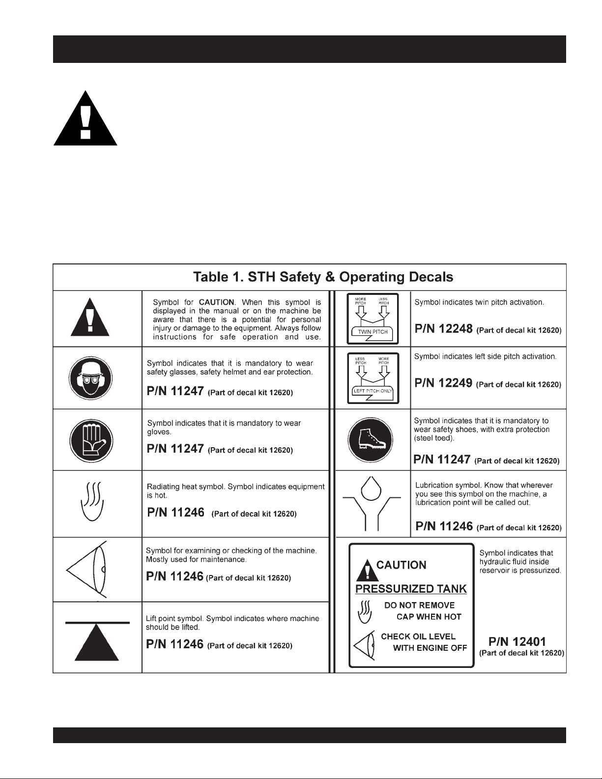
Machine Safety Decals
The STH series Ride-on Power Trowel is equipped with a
number of safety decals. These decals are provided for
operator safety and maintenance information. Table 1 (Page
7) illustrates these decals as they appear on the machine.
Should any of these decals become unreadable, replacements
can be obtained from your dealer.
Page 9
Moving the Ride-On Trowel
CAUTION
STH-55JD-TC — RULES FOR SAFE OPERATION
This ride-on trowel is very
NOT attempt to lift the ride-on trowel by the guard rings.
The STH series Ride-on Power Trowel is designed to be moved and handled several ways. The easiest way to lift the ride-on
trowel is to utilize the lift loops that are welded to the frame. These lift loops are located to the left and right sides of the operator’s
seat (Figure 3, Page 11).
A strap or chain can be attached to these lift loops, allowing a forklift or crane to lift the ride-on trowel up onto a slab of concrete.
The strap or chain should have a minimum 2,000 pounds (1000-kg) lifting capacity and the lifting gear must be capable of lifting
at least this amount.
Table 1 below defines and illustrates the various safety decals used on the ride-on trowel:
heavy
and awkward to move around. Use proper heavy lifting procedures and DO
Note:
See page 57 for addintional decal information.
STH-10 FT. • RIDE-ON POWER TROWEL — PARTS & OPERATION MANUAL — REV. #5 (06/08/05) — PAGE 9
Page 10
STH-55JD-TC — SPECIFICATIONS
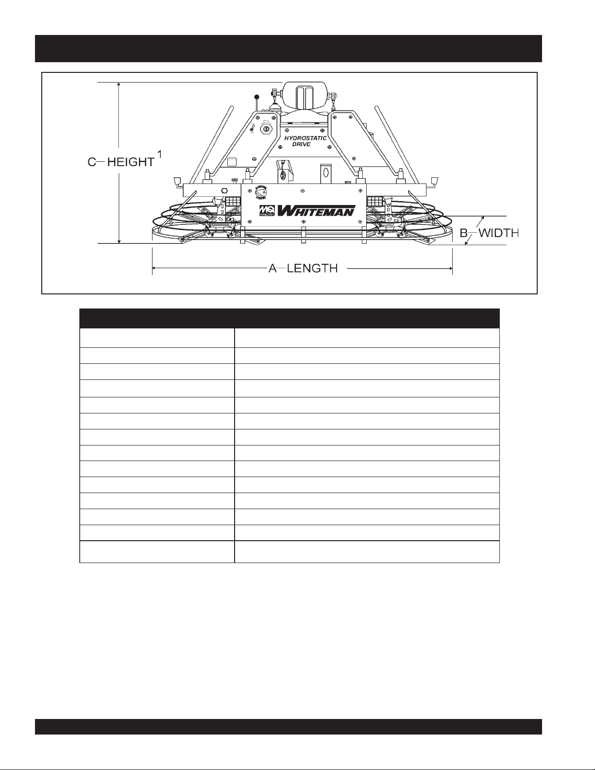
Figure 1. STH Dimension Specifications
snoitacificepSHTS.2elbaT
RETEMARAPNOITACIFICEPS
)mc(.ni–htgneL–A
)mc(.ni–htdiW–B
1
)mc(.ni–thgieH–C
gnitarepO).sgk(.sbl–thgieW
gnippihS).sgk(.sbl–thgieW
2
ABd–erusserPdnuoS
2
s/tf–noitarbiV
2)3
s/m(
)s/m(MPF–deepSpiTedalB
.P.H–enignE
)sretil(snollag–knaTleuF
MPR–rotoR
)mc(.ni–htdiWhtaP
4
liOciluardyH
NOTE:
1. This value includes the seat height.
2. Sound pressure is "A" weighted . Measured at the operators
ear position while the ride-on trowel is operating at full
throttle on concrete in a manner most often experienced in
normal
“
” circumstances. Sound pressure may vary
depending upon the condition of the concrete. Hearing
protection is always recommended.
3. The vibration level indicated is the maximum RMS (Root
Mean Square) value obtained at the handle grip while
operating the ride-on trowel on curing concrete in a
manner most often experienced in “
circumstances. Values were obtained from all three axes
of motion. The values shown represent the maximum
RMS value from these measurements.
4. “AW” stands for
viscosity
and is similar to 10W40-engine oil (hot weather) and
10W30 (cool weather).
LSCT-DJ55-HTS
)813(521
)561(0.56
)241(0.65
)4101(032,2
)1421(0372
79
)5.2(0.8<
)9.9(4291
)egrahcobruTleseiD,ereeDnhoJ(55
)54(21
031ot0
)792(711
)rehtaewdloc(03-W01ro)rehtaewtoh(04-W01ro86VMWA
normal
anti-wear
and “MV” stands for
multi-
. The 68 refers to the general viscosity range
”
PAGE 10 — STH-10 FT. • RIDE-ON POWER TROWEL — PARTS & OPERATION MANUAL — REV. #5 (06/08/05)
Page 11

STH-55JD-TC — GENERAL INFORMATION
STH RIDE-ON TROWEL FAMILIARIZATION
The STH series Ride-On Power Trowels are designed for the
floating and finishing of concrete slabs.
Take a walk around the STH Ride-On Power Trowel. Take notice
of all the entire major components (see Figures 2 and 3, Page
11) like the engine, blades, air cleaner, ignition switch etc. Check
that there is always oil in the engine, and hydraulic oil in the
hydraulic oil reservoir.
Read all the safety instructions carefully. Safety instructions will
be found throughout this manual and on the machine. Keep all
safety information in good, readable condition. Operators
should be well trained on the operation and maintenance of
the STH Ride-On Power Trowel.
Before using your STH Ride-On Power Trowel, test it on a flat
watered down section of finished concrete. This trial test run
will increase your confidence in using the trowel and at the
same time it will familiarize you with the trowel’s controls and
indicators. In addition you will understand how the trowel will
handle under actual conditions.
Engine
The STH Ride-On Power Trowel is available with a standard
55 HP John Deere diesel engine. Refer to the engine owner’s
manual for specific instructions regarding engine operation.
This manual is included with the ride-on trowel at the time of
shipping from Whiteman. Please contact your nearest Multiquip
Dealer for a replacement should the original manual disappear.
Hydraulic Steering
Dual joystick controls located to the left and right of the operator
are provided for steering the STH-Ride on Power Trowel. The
joysticks are linked to three hydraulic steering cylinders located
within the frame of the machine. When the right side steering
joystick is moved either forward or backward it will cause the
right side of the ride-on power trowel to move in either a forward
or reverse direction. Moving the same joystick left or right causes
the trowel to move in either the left or right direction.
When the left side steering joystick is moved, it will cause the left
side of the ride-on trowel to travel in either a forward or reverse
direction.
Hydraulic Pump
Delivers a continuous controlled flow of hydraulic fluid to the
hydraulic motors.
Training
For proper training, please use the “TRAINING CHECKLIST”
located in the front of this manual (Page A). This checklist will
provide an outline for an experienced operator to provide
training to a new operator.
Blades
The blades of the ride-on power trowel finish the concrete as
they are swirled around the surface. Blades are classified as
combination (10 or 8 inches wide), finish (6 inches wide). The
STH is equipped with six blades per rotor equally spaced in a
radial pattern and attached to vertical rotating shaft by means of
spider assembly.
a
Hydraulic Motor
Independent hydraulic drive motors are coupled to the enginepowered hydrostatic pumps. Each motor drives a spider
assembly.
STH-10 FT. • RIDE-ON POWER TROWEL — PARTS & OPERATION MANUAL — REV. #5 (06/08/05) — PAGE 11
Page 12
STH-55JD-TC — CONTROLS AND INDICATORS
Figures 2 and 3 show the location of the controls, indicators and
general maintenance parts. Each control may perform more than
one function. All functions of each control are described below.
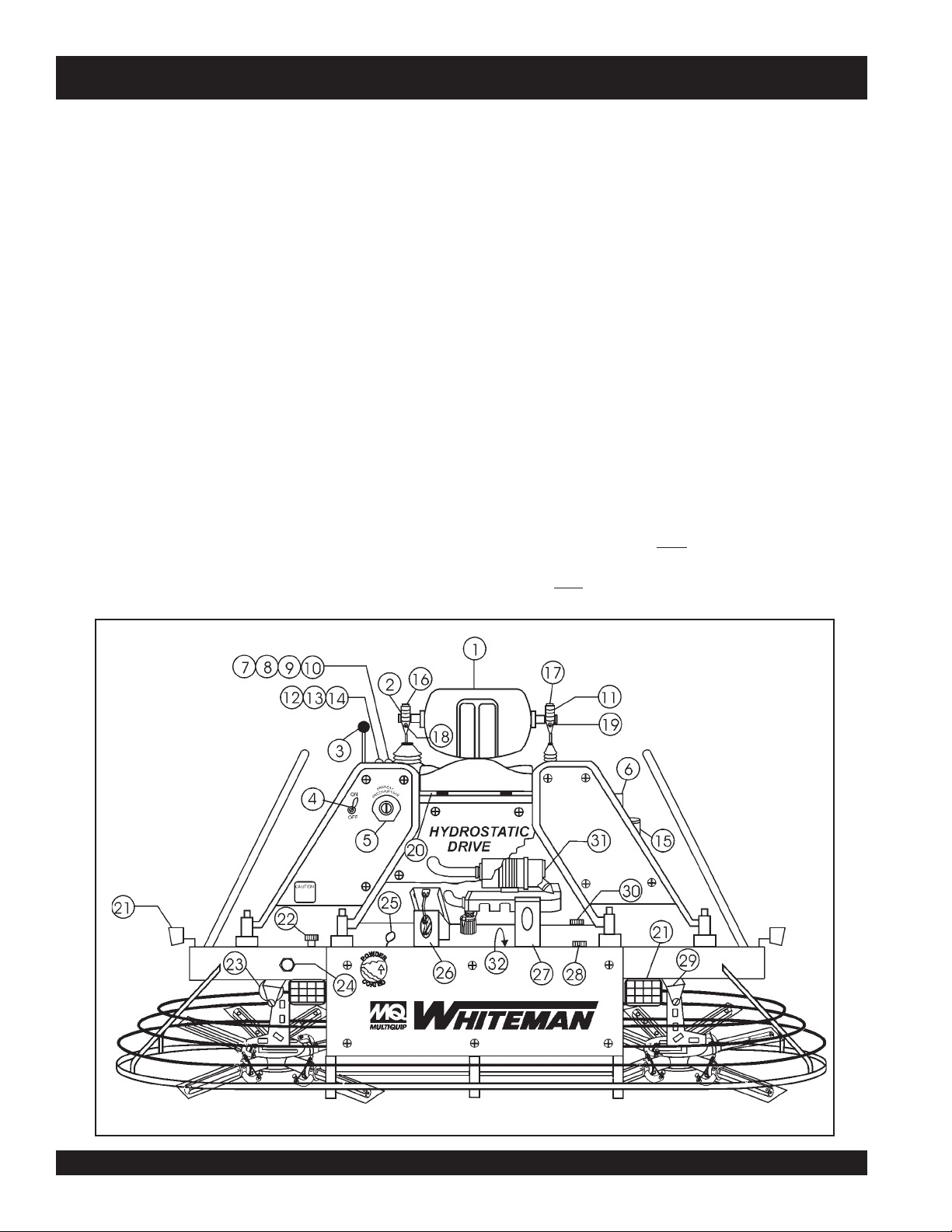
1. Seat – Place for operator to sit. Engine will not start unless
operator is seated. Seat is adjustable for operator comfort.
2. Steering Control (right side) -Allows the unit to move in
either a forward, reverse left or right direction.
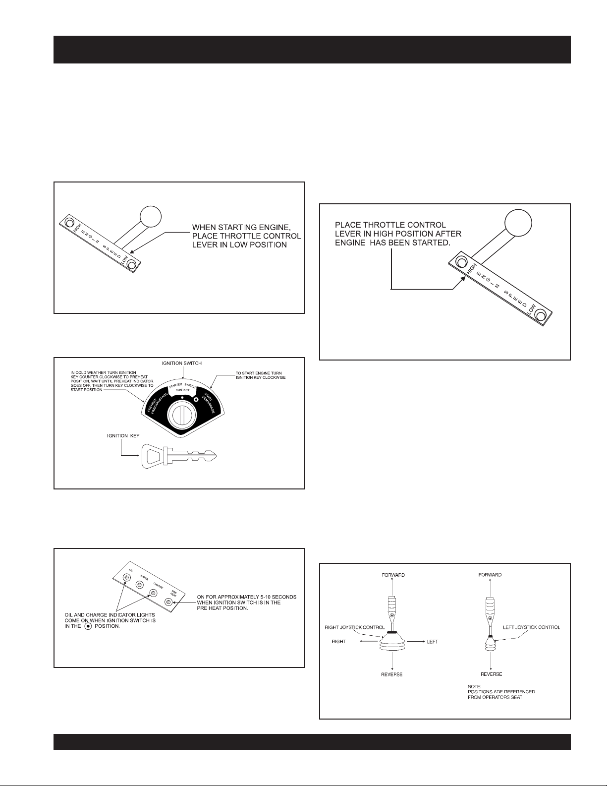
3. Throttle Control Lever – Controls the speed of the engine.
Move the hand lever forward to increase engine speed
(high), backwards to decrease engine speed (low).
4. Light Switch – When activated, turns on six halogen lights.
Lights offer better visibility when working indoors.
5. Ignition Switch – With key inserted turn clockwise to start
engine.
6. Radiator/Filler Cap – Holds coolant or water necessary to
keep engine at a safe operating temperature. Remove this
cap to add water or antifreeze
7. Pre-Heat Indicator Light - Lights blue during engine startup. Indicates that engine glow plugs are being pre-heated.
Light will go off after approximately 10 seconds.
8. Charge Indicator Light - Lights red when electrical system
is not charging properly.
9. Water Indicator Light - Lights red when water temperature
is high.
10. Oil Indicator Light - Lights red when oil pressure is low.
11. Steering Control (left side) - Allows the trowel to move in
a forward or reverse direction only.
12. Tachometer/Hour Meter - Indicates engine speed in
terms of RPM. Also indicates number of hours machine
has been in use.
13. Oil Gauge - Indictes engine oil pressure.
14. Temperature Gauge - Indicates engine coolant
temperature (in degrees faharenheit).
15. Overflow Bottle - Supplies water or coolant to the radiator
when radiator coolant or water level is low. Fill to indicated
level as shown on bottle.
16. Blade Pitch Control Switch (Twin Pitch) - When the
rocker switch is pressed down and to the left it will cause
more pitch to be added to
switch down and to the right will cause less pitch to be
added to
both blades. Pressing the rocker
both blades.
Figure 2. STH Controls and Indicators (Front)
PAGE 12 — STH-10 FT. • RIDE-ON POWER TROWEL — PARTS & OPERATION MANUAL — REV. #5 (06/08/05)
Page 13

STH-55JD-TC — CONTROLS AND INDICATORS
17. Blade Pitch Control Switch (left side) - When the rocker
switch is pressed down and to the left it will cause less
pitch to be added to the left side blades only. Pressing the
rocker switch down and to the right will cause more pitch
to be added to the left side blades only. This switch will not
effect the right side blades for pitch.
18. Retardant Spray Control Button (right side) – When
pressed allows retardant spray to flow through the spray
nozzle located at the right front of the machine.
19. Retardant Spray Control Button (left side) – When
pressed allows retardant spray to flow through the spray
nozzle located at the left front of the machine.
20. Kill Switch – Shuts down engine when operator is not
sitting in seat .
21. Lights – Six Low voltage halogen lights are provided with
this unit.
22. Hydraulic Oil Filler Cap – Remove this cap to add
hydraulic oil.
23. Hydraulic Suction Filter – Filters hydraulic fluid prior to
pump inlet.
24. Hydraulic Oil Sight Glass - Indicates the level of the
hydraulic oil in the reservoir.
25. Engine Dip Stick – Indicates engine oil level. Add oil as
required.
26. Right Foot Pedal – Controls blade speed. Slow blade
speed is accomplished by slightly depressing the foot pedal.
Maximum blade speed is accomplished by fully depressing
the foot pedal.
27. Left Foot Riser – Operator foot rest pedal.
28. Fuel Gauge/Filler Cap - Indicates the amount of fuel in
29. Spray Nozzel – Spray nozzel for retardant. There are two
30. Engine Oil Filler Cap - Remove this cap to add engine oil.
31. Air Filter- Prevents dirt and other debris from entering the
32. Oil Filter- Provides oil filtering for the engine.
33. Lift Loops- Located on both the left and right sides of the
34. Hydraulic Filter - Filters return oil flow from right
35. Hydraulic Filter - Filters return oil flow from left hydrostatic
36. Retardant Spray Tank - Holds 5 gallons of retardant
37. Battery - Provides +12V DC power to the electrical system
38. Retardant Spray Motors- Used in conjunction with the
NOTE
Read this entire instruction manual completely before attempting
to operate this machine.
The following section is intended as a basic guide to the ride-on
trowel operation, and is not to be considered a complete guide
to concrete finishing. It is strongly suggested that all operators
(experienced and novice) read “
the American Concrete Institute, Detroit Michigan.
the fuel tank. Remove this cap to add fuel.
retardant spray nozzels supplied with this unit.
engine.
main frame. Used when the trowel must be lifted onto a
concrete slab.
hydrostatic motor.
motor.
left and right spray control buttons.
Slabs on Grade
” published by
Figure 3. STH Controls and Indicators (Rear)
STH-10 FT. • RIDE-ON POWER TROWEL — PARTS & OPERATION MANUAL — REV. #5 (06/08/05) — PAGE 13
Page 14
STH-55JD-TC — INITIAL START-UP
This section is intended to assist the operator with the initial
start-up of the STH series Ride-On Power trowel. It is extremely
important that this section be read carefully before attempting to
use the trowel in the field.
DO NOT use your ride-on power trowel until this section is
throughly understood.
.CAUTION
Failure to understand the operation of the STH Ride-ON Power
Trowel could result in severe damage to the trowel or personal
injuruy.
See Figures 2 and 3 (Pages 11 and 12) for the location of any
control or indicator referenced in this manual.
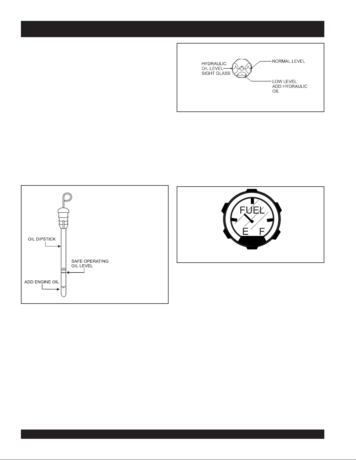
Engine Oil
1. Pull the engine oil dipstick from its holder.
2. Determine if engine oil is low (figure 4), add correct amount
of engine oil to bring oil level to a normal safe level.
Fuel
1. Determine if the engine fuel is low (Figure 6). If fuel level is
low, remove the fuel filler cap and fill with either diesel fuel
or unleaded gasoline depending on the type of engine.
Handle fuel safely. Motor fuels are highly flammable and
can be dangerous if mishandled. DO NOT smoke while
refueling. Do not attempt to refuel the ride-on trowel if the
engine is hot or running.
CAUTIONCAUTION
CAUTION
CAUTIONCAUTION
Figure 5. Hydraulic Oil Sight Glass
Figure 6. Fuel Gauge
Never store the ride-on trowel with fuel in the tank for any
extended period of time. Always clean up spilled fuel immediately.
Figure 4. Engine Oil Dipstick
Hydraulic Oil
1. Determine if the hydraulic oil is low by observing the level
of oil in the Hydraulic Oil Sight Glass (Figure 5).
NOTE
Proper hydraulic operating oil level is MIDDLE of sight glass,
with trowel on level surface, and engine off.
PAGE 14 — STH-10 FT. • RIDE-ON POWER TROWEL — PARTS & OPERATION MANUAL — REV. #5 (06/08/05)
Starting the Engine
1. With one foot on the ground and the other foot placed on
the trowel’s platform, grab hold of any part of the frame and
lift yourself onto the trowel. Then sit down in the operator’s
seat.
2. The Whiteman Ride-On Power trowel is equipped with a
kill switch
safety
assembly. Remember the engine will not start unless an
operator is sitting in the operator’s seat. The weight of an
operator depresses an electrical switch, which will allow
the engine to start.
CAUTIONCAUTION
CAUTION
CAUTIONCAUTION
NEVER disable or disconnect the kill switch. It is provided for the
operators’ safety and injury may result if it is disabled,
disconnected or improperly maintained.
. This switch is located beneath the seat
Page 15
STH-55JD-TC — INITIAL START-UP
3. It is recommended that the kill switch be used to stop the
engine after every use. Doing this will verify that the switch
is working properly and presents no danger to the
operator. Remember to turn the key to the “OFF” position
after stopping the machine. Not doing so may drain your
units’ battery.
4. Place the
position.
Figure 7. Engine Throttle Control Lever (Low)
5. Insert the
engine throttle lever (
ignition key
into the ignition switch (Figure 8).
Figure 7) in the
LOW
NOTE
cold
In
preheat position, wait until the BLUE preheat indicator goes off
before turning the ignition key clockwise to the start position.
7. Turn ignition key fully clockwise and listen for engine to
start. Once engine has started release ignition key. Let
engine warm for a few minutes.
8. Place the
position.
Figure 10. Engine Throttle Control Lever (High)
weather turn the ignition key counter clockwise to the
engine throttle lever
(Figure 10) in the
HIGH
Figure 8. Ignition Switch and Key
6. Turn the ignition key clockwise to the (start) position. The
oil
and charge indicator lights (Figure 9) should be on.
Figure 9. Oil and Charge Indicator Lights
9. The engine should be running at full RPM.
10. Repeat this section a few times to get fully acquainted with
the engine starting procedure.
Steering
Two joysticks (Figure 11) located to the left and right of the
operator’s seat provide directional control for the HTH Ride-On
Power Trowel. Table 3 (Page 15) illustrates the various directional
positions of the joysticks and their effect on the ride-on trowel.
NOTE
All directional references with respect to the joysticks are from
operator’s
the
seat position.
Figure 11. Left and Right Joystick Controls
STH-10 FT. • RIDE-ON POWER TROWEL — PARTS & OPERATION MANUAL — REV. #5 (06/08/05) — PAGE 15
Page 16
STH-55JD-TC — INITIAL START-UP
gninoitisoPlanoitceriDkcitsyoJ3elbaT
KCITSYOJ NOITCERID STLUSER
tfeL drawroFkcitsyoJevoM
tfeL drawkcaBkcitsyoJevoM
thgiR drawroFkcitsyoJevoM
thgiR drawkcaBkcitsyoJevoM
thgiRdnatfeL
thgiRdnatfeL
thgiR thgiRkcitsyoJevoM
thgiR tfeLkcitsyoJevoM
htoBevoM
drawroFskcitsyoJ
htoBevoM
drawkcaBskcitsyoJ
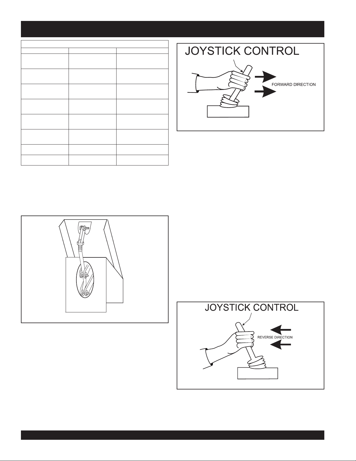
1. The foot pedal (Figure 12) solely controls blade speed.
The position of the foot pedal determines the blade speed.
Slow blade speed is obtained by slightly depressing the
pedal. Maximum blade speed is obtained by fully
depressing the pedal.
edistfelehtylnosesuaC
otlewortno-edirehtfo
.drawrofevom
edistfelehtylnosesuaC
otlewortno-edirehtfo
.drawkcabevom
edisthgirehtylnosesuaC
otlewortno-edirehtfo
.drawrofevom
edisthgirehtylnosesuaC
otlewortno-edirehtfo
.drawkcabevom
lewortno-edirehtsesuaC
nidrawrofevomot
.enilthgiartsa
lewortno-edirehtsesuaC
drawkcabevomot
.enilthgiartsani
lewortno-edirehtsesuaC
.thgirehtotevomot
lewortno-edirehtsesuaC
tfelehtotevomot
Figure 13. Joystick Control Forward Direction
4. Practice holding the machine in one place as you increase
blade speed. When about 75% of maximum blade speed
has been reached, the blade will be moving at proper
finishing speed. The machine may be difficult to keep in
one place. Trying to keep the ride-on trowel stationary is a
good practice for operation.
5. Practice maneuvering the ride-on trowel using the
information listed in Table 3. Try to practice controlled
motions as if you were finishing a slab of concrete.
Practice edging and covering a large area
6. Try adjusting the pitch of the blades. This can be done
with the ride-on trowel stopped or while the trowel is
moving, whatever feels comfortable. Test the operation
of optional equipment like retardant spray and lights if
equipped.
7. Push both the left and right joysticks backward (Figure
14) and repeat steps 3 through 6 while substituting the
word reverse for forward.
Figure 12. Blade Speed Control Foot Pedal
2. Push both the left and right joysticks forward (Figure 13).
3. With your right foot slowly depress the right foot pedal
halfway. Notice that the ride-on power trowel begins to move
in a forward direction. Release both joystick controls to
stop forward movement then remove your right foot from
the right foot pedal.
Figure 14. Joystick Control Reverse Direction
PAGE 16 — STH-10 FT. • RIDE-ON POWER TROWEL — PARTS & OPERATION MANUAL — REV. #5 (06/08/05)
Page 17
STH-55JD-TC — MAINTENANCE
NOTE
See the engine manual supplied with your machine for
appropriate engine maintenance schedule and troubleshooting
guide for problems.
At the front of the book (Page B) there is a “Daily Pre-Operation
Checklist”. Make copies of this checklist and use it on a daily
basis.
CAUTION!CAUTION!
CAUTION!
CAUTION!CAUTION!
Disconnect spark plug wires and battery cables before
attempting any service or maintenance on the ride-on trowel.
MAINTENANCE SCHEDULE
Daily (8-10 Hours)
1. Check the fluid levels in the engine and reservoir, fill as
necessary.
Weekly (30-40 Hours)
1. Relube arms, thrust collar and clutch
2. Replace blades if necessary.
3. Check and clean or replace the engine air filter as
necessary.
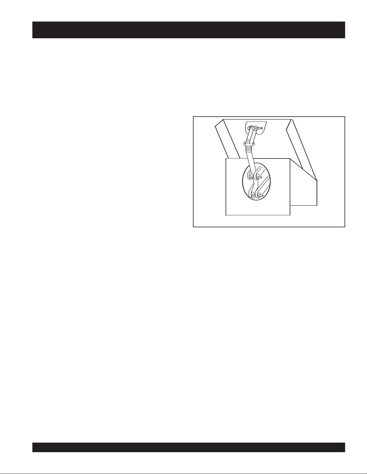
Blade speed adjustment is a two-step process. First, the left
spider’s speed should be checked and/or adjusted. Second,
the right spider’s speed should be adjusted to match the left.
Left Spider Speed Adjustment
The left spider’s speed is adjusted by changing the length of
the rod end spacing (Figure 15) at the front of the foot pedal.
Lengthening the spacing increases the blade speed; shortening
the spacing decreases the blade speed.
Figure 15. Blade Speed Control Foot Pedal
4. Replace engine oil and filter as necessary, see engine
manual.
Monthly (100-125 Hours)
1. Remove, clean, reinstall and relube the arms and thrust
collar. Adjust the blade arms.
Yearly (500-600 Hours)
1. Check and replace if necessary the arm bushings, and
thrust collar bushings.
2. Check pitch control cables for wear.
3. Adjust blade speed.
4. Replace hydraulic fluid and hydraulic filters.
NOTE
After the first 200 hours,
MAINTENANCE PROCEDURES
Checking/Adjusting Blade Speed
Because the two hydraulic drive motors operate independent of
each other, the blade speed between them may vary. If the unit’s
steering is difficult to control, the blade speeds may need to be
checked, or if one spider is spinning noticeably faster or slower
than the other, the blade speed may need to be checked. It is
also recommended that the blade speed be checked at least
once a year.
replace the hydraulic
filter cartridges
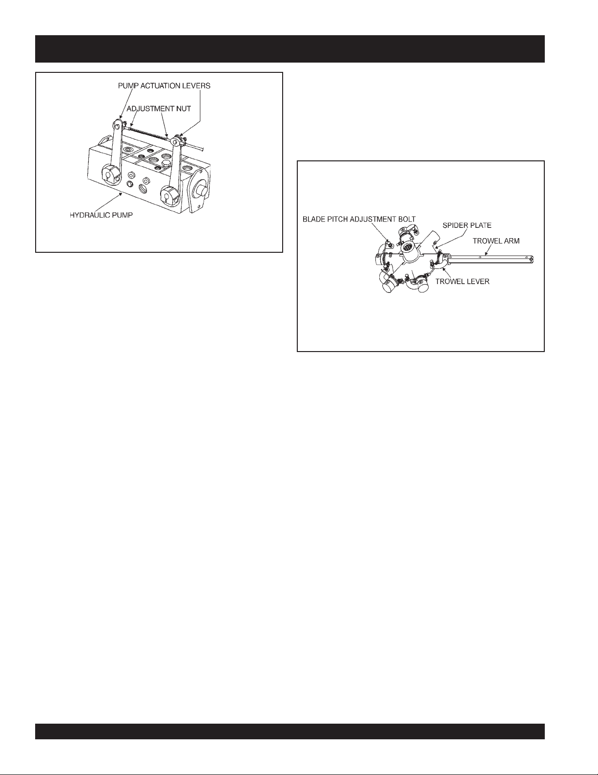
Right Spider Speed Adjustment
The right spider’s speed is adjusted by changing the length of
the connecting rod on the pump actuation levers (Figure 16,
Page 17). This rod is basically a turnbuckle. Rotating it in one
direction increases the length and corresponding spider speed.
Rotating it the opposite direction decreases the length and
spider speed. The right spider’s speed should be within 3 rpm
of the left.
A good starting point in the adjustment process is to adjust the
rod such that both spiders begin to rotate at the same time
when the foot pedal is slowly depressed. This will, generally,
get the speeds close enough for use if instrumentation is
unavailable (i.e. on the job site). From this point on, some form of
instrumentation is required to verify that the right spider speed is
.
within the tolerance specified above. A strobe or magnetic pickup
type speed indicator is recommended to verify the speeds.
The speeds should be adjusted on a dry concrete floor with the
blades pitched flat. The blade speed should be set at 125-130
rpm with the engine at full speed.
Matching Blade Pitch for Both Sets of Blades
STH-10 FT. • RIDE-ON POWER TROWEL — PARTS & OPERATION MANUAL — REV. #5 (06/08/05) — PAGE 17
Page 18
STH-55JD-TC — MAINTENANCE
Blade Pitch Adjustment Procedure
The maintenance adjustment of blade pitch is an adjustment
that is made by a bolt (Figure 17) on the arm of the trowel blade
finger. This bolt is the contact point of the trowel arm to the lower
wear plate on the thrust collar. The goal of adjustment is to promote
consistent blade pitch and finishing quality.
Figure 16. Pump Actuation
Levers/Speed Control Rod
Sometimes it may be necessary to match blade pitch between
the two sets of blades. There are some signs that this may be
necessary. For example, the differences in pitch could cause a
noticeable difference in finish quality between the two sets of
blades. Or, the difference in blade pitch could make the
machine difficult to control. This is due to the surface area in
contact with the concrete (the blade set with the greater contact
area tends to stick to the concrete more).
Twin Pitch
Tr ow el blade pitch is controlled by rocker switches located on
the top of the left and right joystick handles. The rocker switch on
the left handle pitches only the left side blades. The rocker switch
on the right handle pitches blades on both the left and right
sides.
The left side rocker switch is used to "match" blade pitch of the
left and right sides. Once the two sides are "matched" (all blades
on both sides are completely flat), the right side rocker switch
may be used to pitch both sides simultaneously (Twin Pitch).
Important: just as with mechanical Twin Pitch, when using the
right side switch, if the blades on either side reach the maximum
stop
or minimum pitch condition, both sides will
If the pitch angle is significantly different between the left and
right side blades, they must be "matched" (blades), using the left
side rocker switch. Always remember to use the left side rocker
switch first when matching the left and right blades. After both left
and right side blades have been matched then the right side
rocker switch (Twin Pitch) can be used.
pitching.
There are some things to look for when checking to see if
adjustment is necessary. Is the machine wearing out blades
unevenly (i.e. one blade is completely worn out while the others
look new)? Does the machine have a perceptible rolling or
bouncing motion when in use? Look at the machine while it is
running, do the guard rings “rock up and down” relative to the
ground? Do the pitch control cylinders rock back and forth? These
are some of the indications that the blade pitch may need to be
adjusted using the adjustment bolts on the trowel blade finger.
The easiest and most consistent way to make this adjustment is
to use the Trowel Arm Adjustment Fixture (P.N. 9177) . This fixture
will allow consistent adjustment of the trowel arm fingers. It comes
with all the hardware necessary to properly accomplish this
maintenance and instructions on how to properly utilize this tool.
Adjusting the trowel arm fingers without a fixture requires a special
talent.
If a trowel arm adjustment fixture is not available and immediate
adjustment is necessary; we suggest the following procedure.
If you can see or feel which blade is pulling harder, adjust the
bolt that corresponds to that blade. Another way to determine
which blades need adjustment is to place the machine on a
flat surface and pitch the blades as flat as possible. Now, look at
the adjustment bolts. They should all barely make contact with
the lower wear plate on the spider. If you can see that one of
them is not making contact; some adjustment will be necessary.
Figure 17. Blade Pitch Adjustment Bolt
PAGE 18 — STH-10 FT. • RIDE-ON POWER TROWEL — PARTS & OPERATION MANUAL — REV. #5 (06/08/05)
Page 19
STH-55JD-TC — MAINTENANCE
It will be possible to adjust the “high” bolts down to the level of
the one that is not touching, or adjust the “low” bolt up to the
level of the higher ones. If possible, adjust the low bolt up to the
level of the rest of the bolts. This is the fastest way, but may not
always work. Verify that after adjustment, the blades pitch
correctly. Often times, if the blades are incorrectly adjusted, they
will not be able to pitch flat. This occurs when the adjusting
bolts have been raised too high. Conversely, sometimes the
adjusting bolts are too low and the blades cannot be pitched
high enough for finishing operations.
Changing A Blade
Whiteman recommends that all the blades on the entire machine
be changed at the same time. If only one or some of the blades
are changed at one time, the machine will not finish concrete
consistently and the machine may wobble or bounce.
1. Place the machine on a flat, level surface. Adjust the blade
pitch control to make the blades as flat as possible. Note
the blade orientation on the trowel arm. This is important
for ride-on trowels as the two sets of blades counter-rotate.
Lift the machine up, placing blocks under the main guard
ring to support it.
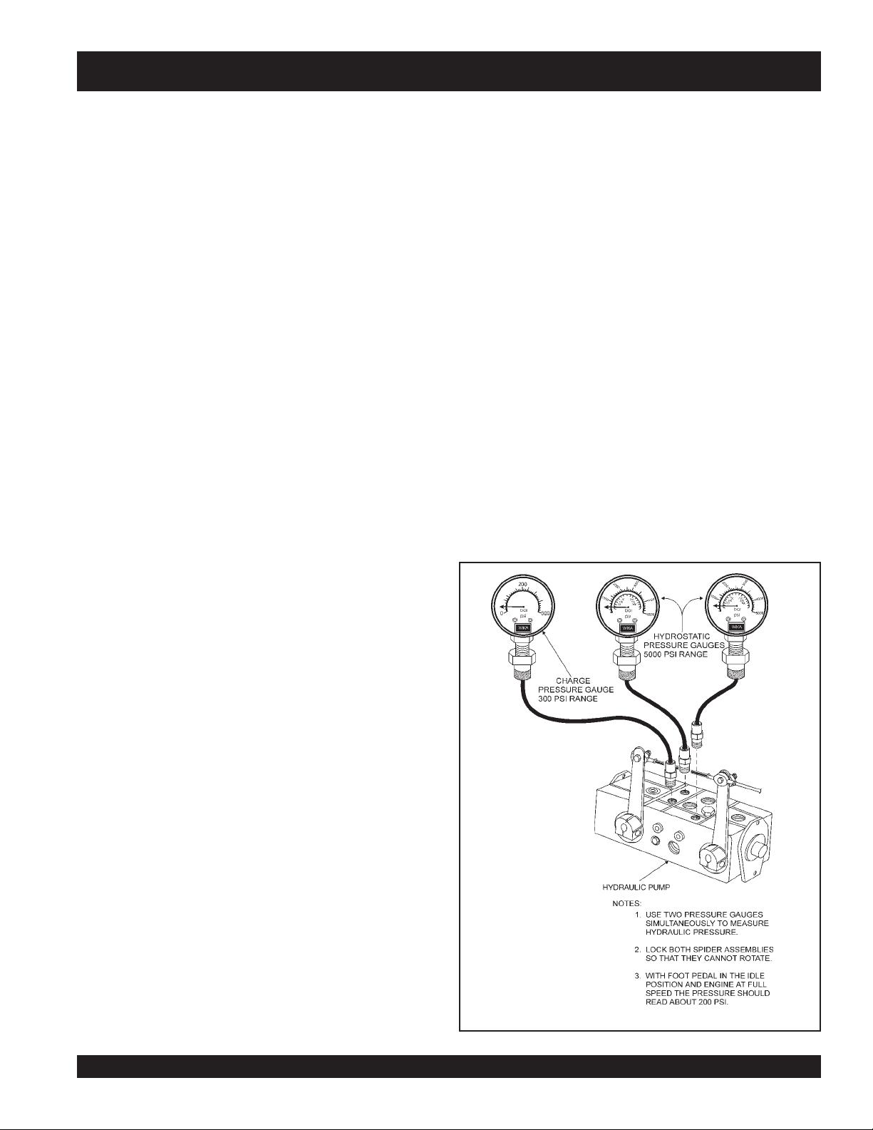
Once the pressure gauges are installed and the spiders chained
together, the system can be checked.
With the engine at 50% to 70% of full speed, and spiders chained
together, slowly depress the foot pedal and read the gauges.
The hydrostatic pressure should get to at least 3,200 psi. If the
hydrostatic pressure will not attain 3,200 psi, the pump should
be inspected and/or serviced by an authorized service
representative.
Checking Charge Pressure
With the foot pedal in the idle position and the engine at full
speed, the pressure should be about 200 psi. This pressure is
referred to as "
checked more accurately using a 300 psi pressure gauge
attached to the charge pressure diagnostic coupler. See Figure
18.
If the charge pressure is less than 150 psi, the charge system
may need to be inspected and/ or serviced. In particular, the
suction filter and charge pump relief valve should be checked.
The suction filter may be plugged, or the relief valve may be
stuck. Either condition may cause low charge pressure.
For STH troubleshooting hints see Table 3 on preceeding page.
Charge Pressure
". Charge pressure can be
2. Remove the bolts and lock washers on the trowel arm,
and then remove the blade.
3. Scrape all concrete and debris from the trowel arm. This
is important to properly seat the new blade.
4. Install the new blade, maintaining the proper orientation
for direction of rotation.
5. Affix the bolts and lock washers.
6. Repeat steps 2-5 for all remaining blades.
Checking Hydraulic Pressure
It should be mentioned that most hydraulic problems are a
result of low fluid levels. Before checking any other possibilities,
make sure the hydraulic fluid level is half way up the sight glass
which is located at the right end of the frame.
Hydrostatic pressure can be checked using a pressure gauge
(Figure 18) with a range of at least 5,000 psi. It is best to use two
gauges simultaneously, but it is possible to use only one gauge
and repeat the procedure for each side.
To fully test the hydrostatic system, the spiders will need to be
locked so that they cannot rotate. This can easily be done by
wrapping a chain around an arm on each spider, thus chaining
them together in the back of the trowel.
Figure 18. Pressure Gauges (Hydraulic)
STH-10 FT. • RIDE-ON POWER TROWEL — PARTS & OPERATION MANUAL — REV. #5 (06/08/05) — PAGE 19
Page 20

STH-55JD-TC — TROUBLESHOOTING
GNITOOHSELBUORT.3ELBAT
MOTPMYS MELBORPELBISSOP NOITULOS
?noitcnuflamhctiwslliK
.lla
tatonrohguorgninnurenignE
?leuF
?noitingI
?smelborprehtO .launams’rerutcafunamenignetlusnoC
.gninoitcnuftonhctiwsllikytefaS
?stcatnocdaB .hctiwsecalpeR
?sedalB
?redipS
?snoitcennoceriwesooL .yrassecensaecalpeR.gniriwkcehC
?smraleworttneB
gneeht
.yltcerrocgninoitcnuf
.yrassecenfihctiwsecalper;detaes
.rabedalbehtotlellarapdna
.yletaidemmitiecalper,tnebylthgilsnevesismra
sirotarepoehtnehwgninoitcnufsihctiwsllikehttahterusekaM
otdeilppusgniebleufsierehterusekaM.metsysleufehttakooL
.deggolctonsiretlifleufehttahterusneotkcehC.eni
sidnarewopsahhctiwsnoitingiehttahterusneotkcehC
.nrowylevissecxeton,noitidnocdoognierasedalbniatrecekaM
ehtmorf)mm05("2nahtsselonerusaemdluohssedalbhsiniF
onerusaemdluohssedalbobmoc,egdegniliartehtotrabedalb
thgiartsebdluohsedalbfoegdegniliarT.)mm98("5.3tahtssel
saelgnahctipemasehttateserasedalbllatahtkcehC
rofelbaliavasiloottnemtsujdadleifA.redipsehttaderusaem
.)tnempiuqElanoitpOees(smralewortehtfotnemtsujdathgieh
ehtfoenofI.smraleworttnebrofylbmessaredipsehtkcehC
sllor,secnuob“lewortfI
nevenusekamro,etercnoc
.”etercnocnislriws
?hctipedalB
?tfahsniaM
elbitpecrepasahenihcaM
.gninnurelihwnoitomgnillor
?ekoY
?sedalB
?sgnihsubmraleworT
er
?ralloctsurhT
?gnihsubralloctsurhT
?nrowgniraebtsurhT
.yrassecenfisnoitcurtsni
.tnioptnemhcatta
.sedalbrehtollasahctip
.ralloctsurhtehtnignihsubehtecalper
.yrassecenfiecalper,pactsurhT
.yrassecensaekoyecalpeR.pacraeweht
ybenodebnacsihT.ssenthgitrofsgnihsubmralewortehtkcehC
"8/1nahteromsierehtfI.nwoddnapusmralewortehtgnivom
ebdluohssgnihsubeht,mraehtfopitehttalevartfo)mm2.3(
.emitemasehttadecalperebdluohssgnihsubllA.decalp
.redipsehtnotignitatorybralloctsurhtehtfossentalfehtkcehC
.ralloctsurhtehtecalper)mm5.0("20.0nahteromybseiravtifI
tlitnactifI.redipsehtnotignikcorybralloctsurhtehtkcehC
,].D.Oralloctsurhtehttaderusaemsa[)mm4.2("23/3nahterom
:etoN.eerfgninnipssititahteesotgniraebtsurhtehtkcehC
noitcesecnanetniaMreptsujdA.hctiptnetsisnocrofsedalbkcehC
ebdluohsylbmessaxobraegehtfotfahstuptuoniamehT
dnathgiartsnurtsumtfahsniamehT.ssenthgiartsrofdekcehc
redipsehttadnuorfotuo)mm80.0("300.0nahteromebtonnac
noylnevesserpekoyehtfosregnifhtobtahterusekamotkcehC
emasehtevahotdetsujdasiedalbhcaetahterusneotkcehC
PAGE 20 — STH-10 FT. • RIDE-ON POWER TROWEL — PARTS & OPERATION MANUAL — REV. #5 (06/08/05)
Page 21

STH-55JD-TC — TROUBLESHOOTING
)DEUNITNOC(GNITOOHSELBUORT.3ELBAT
MOTPMYS MELBORPELBISSOP NOITULOS
?gniriW
.gnikrowton)lanoitpo(sthgiL
?sthgiL .nekorbfiecalpeR.doogllitserasblubthgilfieesotkcehC
?tnadrateR
?gniriW
.gnikrowton)lanoitpo(yarpstnadrateR
?hctiwsdaB
?pmupyarpsdaB
?tnemtsujdafotuodeepsedalB
?stnenopmocnroW
.evisnopsernusignireetS
?stoviP
?erusserpciluardyH
calpeR
.erusserpciluardyh
.yrassecensagniriwdnastnenopmoce
.nekorbfiecalpeR.hctiwsffo/noretsamfoytiunitnocehtkcehC
.pmupehtecalper,doogerapmupehtotsnoitcennoclacirtceledna
.tnemtsujdadeepsedalbnonoitceseeS
.srotomevirdciluardyhfotnemevomeerferusneotkcehC
otkcehcdnahctiwsffo/noretsamehtgnidulcni,snoitcennoclacirtcelellakcehC
.yrassecensaecalpeR.strohsonhtiwnoitidnocdoognisigniriwfiees
.yrassecensaknatlliF.tneserpsitnadratererusekamotknatehtkcehC
.snoitcennochctiwsffo/noretsamgnidulcni,snoitcennoclacirtcelellakcehC
etarepotonseodtub,nodenrutsihctiwsehtnehwtneserpegatlovasahpmupfI
.yrassecenfiecalperstnenopmocegaknildnasgniraebgnireetsforaewrofkcehC
gnikcehcnonoitceseeS.etauqedasierusserpciluardyhtahterusneotkcehC
.elbatrofmocnusinoitisopgnitarepO ?rotareporoftsujdataeS
?strapesoolronekorB .snoitcennocesohhctipciluardyhkcehC
?gniriW
gnikrowtonslortnoChctiP
?hctiwS
?tnemtsujdaedis-ot-ediS
?noitcnuflamevlavhtciP
.margaidgniriwHTS
.yletaidemmi
.hctipedalbnonoitcesecnanetniameeS
.taesehtfotnorfehtnodetacolrevelhtiwtaestsujdA
eeS.hctiwsrekcordnaylbmessaevlavlortnochtcipneewtebsnoitcennockcehC
ecalper,gninoitcnuflamerasehctiwsfI.sehctiwsrekcorehtfoytiunitnocehtkcehC
.hctipedalbnonoitcesecnanetniameeS.tuobadehctiperasedishtobtahterusnE
.ylreporpgninoitcnuferasdionelosllatahterusneotnoitarepoevlavhctipkcehC
STH-10 FT. • RIDE-ON POWER TROWEL — PARTS & OPERATION MANUAL — REV. #5 (06/08/05) — PAGE 21
Page 22

STH-55JD-TC — EXPLANATION OF CODE IN REMARKS
How to read the marks and remarks used in this parts
book.
Items Found In the “Remarks” Column
Serial Numbers-Where indicated, this indicates a serial
number range (inclusive) where a particular part is used.
Model Number-Where indicated, this shows that the
corresponding part is utilized only with this specific model
number or model number variant.
Items Found In the “Items Number” Column
All parts with same symbol in the number column,
■
, belong to the same assembly or kit.
, #, +, %, or
*
COLUMN
NOTE
If more than one of the same reference number is
listed, the last one listed indicates newest (or latest)
part available.
NOTE
The contents of this catalog are
subject to change without notice
PAGE 22 — STH-10 FT. • RIDE-ON POWER TROWEL — PARTS & OPERATION MANUAL — REV. #5 (06/08/05)
.
Page 23

STH-55JD-TC — SUGGESTED SPARE PARTS
ENGINE JOHN DEERE JD4020TF005, 55 HP
1 Unit
Qty. P/N Description
1 ............ 11577 .................... MOUNT, MACHINERY
1 ............ 10568 .................... THROTTLE CABLE ASSY
3 ............ JDRG600690 ........ AIR FILTER
3 ............ JDM801209 .......... FUEL FILTER
4 ............ 11141 .................... SPACER ROD END
2 ............ 11142 .................... ROD END
2 ............ 12038 .................... BELLOWS
1 ............ 12099 .................... VALVE STRG. LEFT SIDE
1 ............ 12171 .................... SEAL, WEATHERPACK
1 ............ 12172 .................... SEAL, CABLE PACKARD
1 ............ 12519 .................... BOOT, LEFT SIDE
1 ............ 12518 .................... BOOT, RIGHT SIDE
1 ............ HUP51999 ............ BOLT ASSY, PIVOT
1 ............ HU5177-1 ............. BOLT-PIVOT
1 ............ 12487 .................... BOOT TOP HANDLE
2 ............ OEM2783AM ......... 2-PIECE HANDLE
4 ............ OEMAA9 ............... ROCKER ASSY.
2 ............ 12474 .................... MICROSWITCH
1 ............ 12473 .................... 10 AMP PUSHBUTTON SPST PB SW.
1 ............ 12091 .................... ROD PUMP ACTUATOR
2 ............ 12148 .................... CAP, DUST
1 ............ 11491 .................... CABLE, FOOT PEDAL
2 ............ 12126 .................... ELEMENT FILTER (RETURN)
1 ............ 11884 .................... ELEMENT FILTER (SUCTION)
2 ............ 11991 .................... ARM, TROWEL
3 ............ 9005 ...................... LEVER, LEFT SIDE
6 ............ 11039 .................... BUSHING
1 ............ 10221 .................... BUSHING, 1 I.D. 1 1/8 O.D. 1 LG.
3 ............ 9111 ...................... SPRING, LEFT SIDE
1 ............ 11992 .................... PLATE, SPIDER
2 ............ 12607 .................... CAP KIT, THRUST
3 ............ 2143 ...................... SPRING, RIGHT SIDE
3 ............ 1986 ...................... LEVER, RIGHT SIDE
1 ............ 12371 .................... BOLT
1 ............ 11940 .................... RETAINER
1 ............ 11593 .................... SEAT, SPRING
1 ............ 12005 .................... SWITCH, KILL
1 ............ 4682 ...................... SWITCH, LIGHT
1 ............ 11792 .................... SOLENOID
1 ............ 11418 .................... CAP, FUEL W/GAUGE
1 ............ 12332 .................... CAP, HYDRAULIC RESERVOIR
2 ............ 11641 .................... SPRING, SPEED CONTROL
3 ............ 11643 .................... ROD END
4 ............ 1484 ...................... BUSHING BRONZE
1 ............ 1597 ...................... BATTERY CABLE (-)
1 ............ 10314 .................... BATTERY CABLE (+)
1 ............ 10021 .................... PUMP SPRAY (OLD STYLE)
1 ............ 12628 .................... PUMP SPRAY (NEW STYLE)
1 ............ 2108 ...................... CAP, SPRAY TANK
Qty. P/N Description
1 ............ 2816 ...................... COVER SPRAY MOTOR (OLD)
1 ............ 392292 .................. NOZZLE, SPRAY
1 ............ 2532 ...................... LIGHT, HALOGEN
1 ............ 12009 .................... SCREEN FILTER
1 ............ 12620 .................... DECAL KIT
1 ............ 11098 .................... CIRCUIT BREAKER, 40 AMP
1 ............ 8381 ...................... BOOT, SWITCH
1 ............ 11418 .................... FUEL CAP
2 ............ 11611 .................... ROD END (FEMALE)
1 ............ 11638 .................... ADAPTER SPEED CTRL. SPRING
1 ............ 12091 .................... ROD, PUMP ACTUATOR
4 ............ GE #57.................. 12V DC BULB, INDICATOR LIGHTS
ENGINE PARTS FOR JOHN DEERE STH55JDTC
1 ............ JDM801209 .......... OIL FILTER
1 ............ JDT111383 ........... FUEL FILTER
1 ............ JDRG60690 .......... AIR FILTER
1 ............ JDRG60514 .......... TACHOMETER
1 ............ JDRG60509 .......... OIL PRESSURE GAUGE
1 ............ JDRG60504 .......... WATER TEMPERATURE GAUGE
1 ............ JDM801118 .......... MANIFOLD HEATER
1 ............ JDM801821 .......... FAN BELT
3 ............ JDRG60049 .......... PLUG, INDICATOR LIGHT (RED)
1 ............ J DRG60051 ......... PLUG, INDICATOR LIGHT (BLUE)
1 ............ 11924 .................... SWITCH IGNITION
1 ............ 12001 .................... STARTER KEYS ( 2 per set)
NOTE:..................... Part numbers on this
Suggested Spare Parts List may supercede/
replace the P/N shown in the text pages of this
book.
NOTE
Part numbers on this Suggested
Spare Parts List may supercede/
replace the P/N shown in the text
pages of this book.
STH-10 FT. • RIDE-ON POWER TROWEL — PARTS & OPERATION MANUAL — REV. #5 (06/08/05) — PAGE 23
Page 24
STH-55JD-TC — PIVOT ASSY. (LEFT)
PAGE 24 — STH-10 FT. • RIDE-ON POWER TROWEL — PARTS & OPERATION MANUAL — REV. #5 (06/08/05)
Page 25

STH-55JD-TC — PIVOT ASSY. (LEFT)
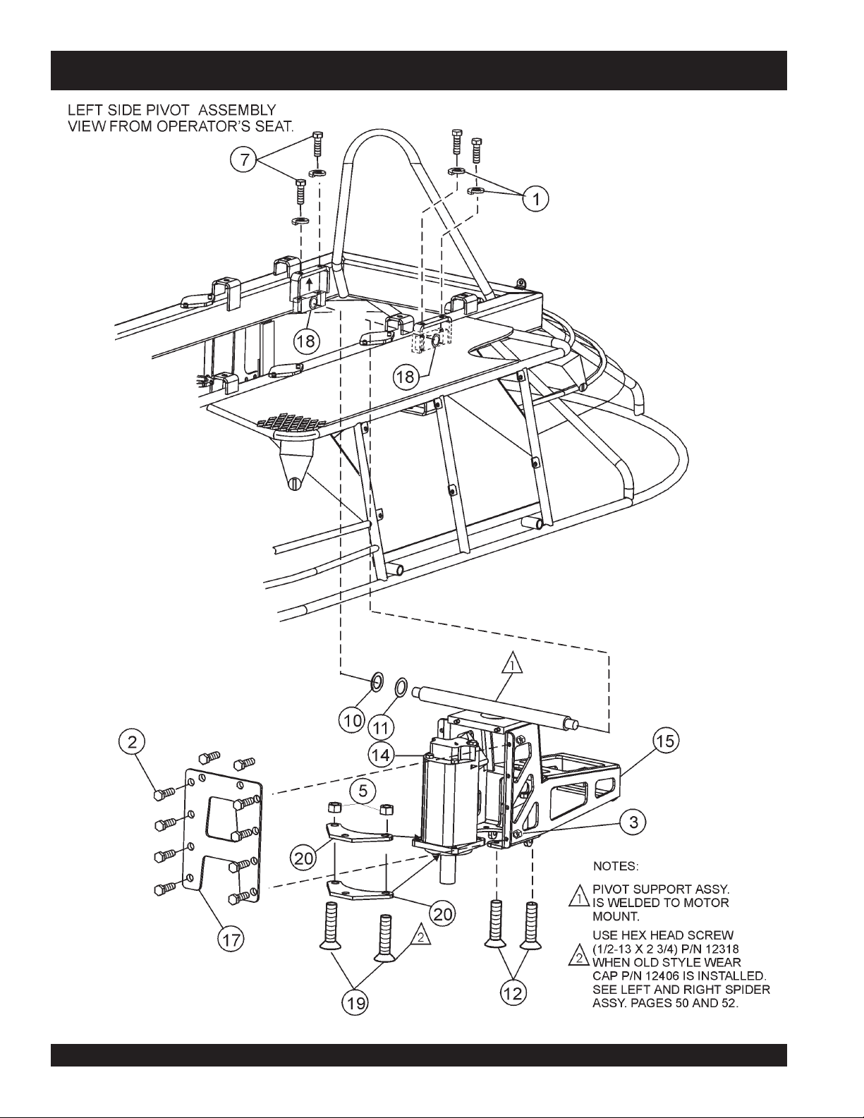
LEFT PIVOT ASSY.
NO PART NO PART NAME QTY REMARKS
1 0166 A WASHER, LOCK, 3/8 MED 4
2 0205 SCREW, HHC 3/8-16 X 1 10
3 10133 NUT, NYLOC 3/8-16 8
5 10176 NUT, NYLOC 1/2-13 4
7 1023 SCREW, HHC 3/8-16 X 1 1/4 4
10 11772 SHIM, TRUNNION .063 THICK 1
11 11773 SHIM, TRUNNION .031 THICK 1
12 11882 SCREW, FHSC 1/2-13 X 2 1/4 2
14 12112 MOTOR, HYD STH 112-11209 1
15 12291 MOUNT, HYD MOTOR LEFT W/A 1
17 12295 PLATE, HYD MOTOR MOUNT END 1
18 12304 ROCKER BLOCK 2
19 12591 SCREW, FLUSH HEAD 1/2-13 X 3 ................ 2 ........... STH UNITS S/N IK60764 AND LATER. ALSO SEE NOTE
20 12480 PLATE, MOTOR STEERING MT 2
NOTE:
IF WEAR CAP 12406 IS INSTALLED (STH's WITH S/N IK60763 AND BELOW) USE P/N 12318 (SCREW, HEX HEAD 1/2-13 X 2 3/4).
STH-10 FT. • RIDE-ON POWER TROWEL — PARTS & OPERATION MANUAL — REV. #5 (06/08/05) — PAGE 25
Page 26
STH-55JD-TC — PIVOT ASSY. (RIGHT)
PAGE 26 — STH-10 FT. • RIDE-ON POWER TROWEL — PARTS & OPERATION MANUAL — REV. #5 (06/08/05)
Page 27

STH-55JD-TC — PIVOT ASSY. (RIGHT)
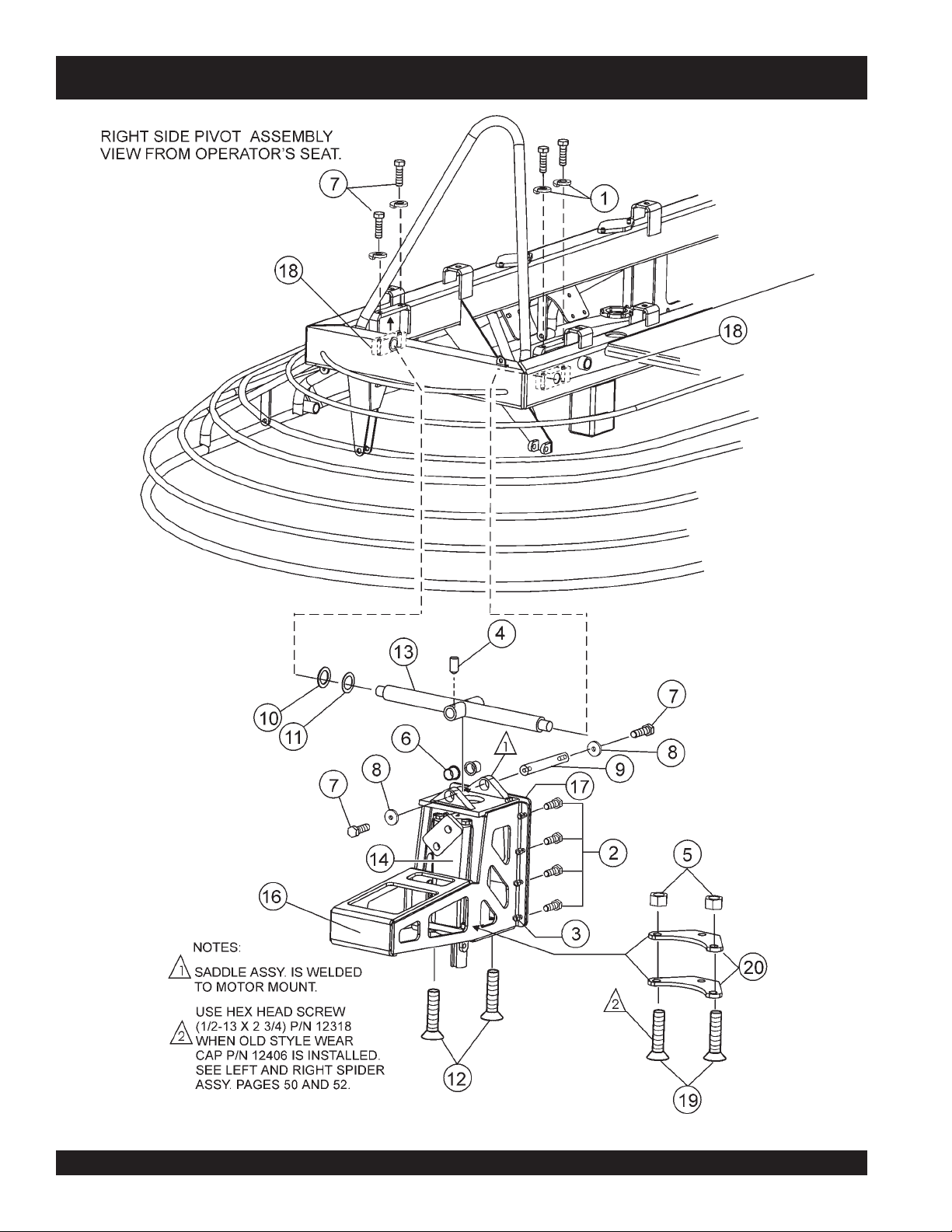
RIGHT PIVOT ASSY.
NO PART NO PART NAME QTY REMARKS
1 0166 A WASHER, LOCK, 3/8 MED 4
2 0205 SCREW, HHC 3/8-16 X 1 10
3 10133 NUT, NYLOC 3/8-16 8
4 10138 SCREW, SHS 1/4-20 X 1/2, N.P. 1
5 10176 NUT, NYLOC 1/2-13 4
6 10221 BUSHING, 1ID X 1.1/8 OD X 1 LG 2
7 1023 SCREW, HHC 3/8-16 X 1 1/4 6
8 11154 RETAINER, CENTRIFUGAL CLUTCH 1
9 11420 SHAFT, PIVOT 1
10 11772 SHIM, TRUNNION .063 THICK 1
11 11773 SHIM, TRUNNION .031 THICK 1
12 11882 SCREW, FHSC 1/2-13 X 2 1/4 2
13 12086 TRUNNION W/A 1
14 12112 MOTOR, HYD STH 112-11209 1
16 12292 MOUNT, HYD MOTOR RIGHT W/A 1
17 12295 PLATE, HYD MOTOR MOUNT END 1
18 12304 ROCKER BLOCK 2
19 12591 SCREW, FLUSH HEAD 1/2-13 X3 2 STH UNITS S/N IK60764 AND LATER. ALSO SEE NOTE
20 12480 PLATE, MOTOR STEERING MOUNT 2
NOTE:
IF WEAR CAP 12406 IS INSTALLED (STH's WITH S/N IK60763 AND BELOW) USE P/N 12318 (SCREW, HEX HEAD 1/2-13 X 2 3/4).
STH-10 FT. • RIDE-ON POWER TROWEL — PARTS & OPERATION MANUAL — REV. #5 (06/08/05) — PAGE 27
Page 28

STH-55JD-TC — PITCH ASSY. (RIGHT)
PAGE 28 — STH-10 FT. • RIDE-ON POWER TROWEL — PARTS & OPERATION MANUAL — REV. #5 (06/08/05)
Page 29

STH-55JD-TC — PITCH ASSY. (RIGHT)
PITCH (RIGHT) ASSY.
NO PART NO PART NAME QTY REMARKS
1 0166A WASHER, LOCK, 3/8 MED 2
2 0183 PIN, COTTER 1/8 X 1 ¼ 2
3 0202 SCREW, HHC 1/16-18 X 1 1
4 0448 WASHER, FLAT, 7/16 SAE 2
5 11648 SHAFT, YOKE PIVOT 2
6 11699 HOSE, BLACK 52. 1/2, 3/8ID 2
7 11721 FITTING, STR 6MJ-6MO 3
8 11722 FITTING, 90 6MJ-6MO 2
9 11780 FITTING, 45 6MJ-6MO 1
10 11889 FITTING, 45 6MJ-8MO 2
11 11966 CYLINDER, STH PITCH 1
13 11972 CONNECTOR ROD END, 3/4 MALE 1
14 12030 YOKE, STH PITCH LONG ARM 1
16 12096 BELLOWS, PITCH CYLINDER 1
17 12116 VALVE ASM, PITCH CONTROL STH 1
19 12151 SCREW, HHC 3/4-10 X 2-3/4 1
20 12159 FITTING, TEE 6MJ-6MO-6MJ RUN 1
21 12183 WIRE ASM, STH CTRL 1 STH S/N ABOVE IJ60711
21 12579 WIRE ASM, STH CTRL 1 STH S/N BELOW IJ60710
22 12257 HOSE ASM, 3/8 ID X 24L 06FJ 1
23 12246 TUBE, HYD, MANIFOLD DRAIN 1
24 12247 FITTING, 90 6MJ-3/8MP 1
25 12259 TUBE, HYD PITCH CYL BASE 1
26 12260 TUBE, HYD PITCH CYL ROD 1
30 12277 CLAMP, WORM HOSE 46/70 MM 1
31 1648 NUT, HEX JAM 3/4-16 1
32 4196 SCREW, HHC 3/8-16 X 3/4 2
33 5070B NUT, NYLOC 3/4-10 1
34 5283 NUT, NYLOC 5/16-18 1
35 60103 TIE WRAP, .312W X 8L X .082 THK 1
36 8128 CLAMP, HOSE SUPPORT, 5/16" 1
37 12244 TUBE, HYD STEERING RETURN 1
38 12213 HOSE ASM, 3/8 X 90 ONE END 1
1 0166A WASHER, LOCK, 3/8 MED 2
2 0183 PIN, COTTER 1/8 X 1 1/4 4
STH-10 FT. • RIDE-ON POWER TROWEL — PARTS & OPERATION MANUAL — REV. #5 (06/08/05) — PAGE 29
Page 30

STH-55JD-TC — PITCH ASSY. (LEFT)
PAGE 30 — STH-10 FT. • RIDE-ON POWER TROWEL — PARTS & OPERATION MANUAL — REV. #5 (06/08/05)
Page 31

STH-55JD-TC — PITCH ASSY. (LEFT)
PITCH (LEFT) ASSY.
NO PART NO PART NAME QTY REMARKS
2 0183 PIN, COTTER 1/8 X 1 ¼ 2
4 0448 WASHER, FLAT, 7/16 SAE 2
5 11648 SHAFT, YOKE PIVOT 1
11 11966 CYLINDER, STH PITCH 1
12 11969 YOKE, STH PITCH SHORT ARM 1
13 11972 CONNECTOR ROD END, 3/4 MALE 1
15 12079 HOSE ASM, 3/8 X 17 STR ENDS 2
16 12096 BELLOWS, PITCH CYLINDER 1
18 12138 CLAMP BASE, 3/8 TUBE DOUBLE 1
19 12151 SCREW, HHC 3/4-10 X 2-3/4 1
25 12259 TUBE, HYD PITCH CYL BASE 1
26 12260 TUBE, HYD PITCH CYL ROD 1
27 12273 CLAMP, 3/8 TUBE PLASTIC PAIR 3
28 12274 COVER, CLAMP STAUFF USDS1 3
29 12275 SCREW, CLAMP STAUFF ASDS1 3
30 12277 CLAMP, WORM HOSE 46/70MM 2
31 1648 NUT, HEX JAM 3/4-16 1
33 5070B NUT, NYLOC 3/4-10 1
35 60103 TIE WRAP, .312W X 8L X .082THK 1
STH-10 FT. • RIDE-ON POWER TROWEL — PARTS & OPERATION MANUAL — REV. #5 (06/08/05) — PAGE 31
Page 32

STH-55JD-TC — ENGINE (JOHN DEERE)
HTH — ENGINE (VANGUARD)HTH — ENGINE (VANGUARD)
PAGE 32 — STH-10 FT. • RIDE-ON POWER TROWEL — PARTS & OPERATION MANUAL — REV. #5 (06/08/05)
Page 33

STH-55JD-TC — ENGINE (JOHN DEERE)
ENGINE (JOHN DEERE)
NO PART NO PART NAME QTY. REMARKS
2 0166 A WASHER, LOCK, 3/8 MED 8
3 0205 SCREW, HHC 3/8-16 X 1 2
4 0447 WASHER, FLAT, 1/2 SAE 2
5 10133 NUT, NYLOC 3/8-16 2
6 10136 WASHER, FLAT, 3/8 SAE 10
7 10176 NUT, NYLOC 1/2-13 1
8 11577 MOUNT, MACHINERY 5
9 11691 SCREW, HHC 3/8-24 X 3/4 1
10 11799 MOUNT, LEFT MOTOR 2
11 11854 MOUNT, RIGHT MOTOR W/A 1
12 12033 SUPPORT, PUMP TAIL 1
13 12035 SUPPORT, PUMP W/A 1
19 16056 SCREW, HHC M10-1.5 X 25 MM 16
21 2955 WASHER, LOCK, 7/16 20
22 5054 A WASHER, LOCK, 1/2 MED. 9
23 5218 SCREW, HHC 1/2-13 X 1 ½ 8
25 6159 A SCREW, HHC 1/2-13 X 2 1
26 6869 SCREW, HHC 3/8-24 X 1/2 7
30 2153 ROD END 1
31 3513 SCREW 1
32 0937 NUT, HEX 1
33 10019 NUT, NYLOC 1
34 10568 CABLE THROTTLE 1
STH-10 FT. • RIDE-ON POWER TROWEL — PARTS & OPERATION MANUAL — REV. #5 (06/08/05) — PAGE 33
Page 34

STH-55JD-TC — ENGINE (JOHN DEERE)
PAGE 34 — STH-10 FT. • RIDE-ON POWER TROWEL — PARTS & OPERATION MANUAL — REV. #5 (06/08/05)
Page 35

STH-55JD-TC — ENGINE (JOHN DEERE)
ENGINE (JOHN DEERE)
NO PART NO PART NAME QTY. REMARKS
1 0161C WASHER, LOCK, 5/16 MED 6
14 12041 MOUNT AIR FILTER 1
15 12071 RADIATOR BRACKET, LARGE 1
16 12104 ENGINE JD4020TF005, 55 HP 1 JOHN DEERE
17 12122 COVER, RADIATOR 1
20 2866 SCREW, HHC M8-1.25 X 20 MM 6
24 60049 TRIM EDGE 1/32 (62B3-1/32) 2
27 0131 A SCREW 2
28 0181 B LOCK WASHER 2
29 0948 WASHER, FLAT, 5/16 SAE 2
35 0300 B FLAT WASHER 4
36 121256-44600 BRACKET, OVERFLOW BOTTLE 1 NORTHSTAR
37 JDRG60690 AIR FILTER (ELEMENT) 1
38 JDT111383 FUEL FILTER 1
39 JDM801209 OIL FILTER 1
40 12617 MUFFLER 1
41 JDRG60510 OIL SENDER UNIT 1
42 JDT110736 WATER TEMP. SENDER UNIT 1
43 TC007 7 FT. TACHOMETER CABLE 1
44 JDRG60688 CANNISTER, AIR FILTER 1
45 JDM81118 HEATER 1
STH-10 FT. • RIDE-ON POWER TROWEL — PARTS & OPERATION MANUAL — REV. #5 (06/08/05) — PAGE 35
Page 36

STH-55JD-TC — HYDRAULIC STEERING (LEFT) ASSY.
PAGE 36 — STH-10 FT. • RIDE-ON POWER TROWEL — PARTS & OPERATION MANUAL — REV. #5 (06/08/05)
Page 37

STH-55JD-TC — HYDRAULIC STEERING (LEFT) ASSY.
HYDRAULIC STEERING (LEFT) ASSY.
NO PART NO PART NAME QTY. REMARKS
1 0161 C WASHER, LOCK, 5/16 MED. 4
2 0300 B WASHER, FLAT, 5/16 SAE 4
3 10176 NUT, NYLOC 1/2-13 2
4 10229 SCREW, HHC 5/16-24 X 1 4
5 11141 SPACER, ROD END 4
6 11142 ROD END, 1/2-20 MALE RH 2
7 11146 NUT, HEX JAM 1/2-20 2
8 11676 TUBE, HANDLE 1
11 11722 FITTING, 90 6MJ-6MO 1
12 11723 FITTING, 90 6MJ-8MO 1
13 11725 FITTING, STR 6MJ-1/4MP 2
14 11780 FITTING, 45 6MJ-6MO 2
15 12038 BELLOWS, STEERING CYL. 1
16 12055 HOSE ASM, 3/8X36 LNG 45 ONE END 2
17 12056 CYLINDER, HYD STEERING 1
18 12060 PLATE, BELLOWS MOUNTING 1
20 12099 VALVE, STRG LSIDE HUSCO7470-A47 1
21 12115 HANDLE, STEERING TWO SWITCH 1
24 12141 TUBE, HYD STEERING PRESSURE 1
25 12142 TUBE, HYD STEERING RETURN 1
27 12171 SEAL, WEATHERPACK 16-18 GA 1
28 12172 SEAL, CABLE PACKARD 39004 3
29 12177 CONNECTOR ELEC PACKARD 38046 1
30 12223 TERMINAL, MALE PACKARD 30034 4
36 12402 SCREW, HHC 1/2-13 X2 1/2 2
41 0447 WASHER FLAT 1/2 SAE 2
30. 12223 TERMINAL, MALE PACKARD 30034 8
STH-10 FT. • RIDE-ON POWER TROWEL — PARTS & OPERATION MANUAL — REV. #5 (06/08/05) — PAGE 37
Page 38

STH-55JD-TC — HYDRAULIC STEERING (RIGHT) ASSY.
PAGE 38 — STH-10 FT. • RIDE-ON POWER TROWEL — PARTS & OPERATION MANUAL — REV. #5 (06/08/05)
Page 39

STH-55JD-TC — HYDRAULIC STEERING (RIGHT) ASSY.
HYDRAULIC STEERING (RIGHT) ASSY.
NO PART NO PART NAME QTY. REMARKS
1 0161 C WASHER, LOCK, 5/16 MED. 8
2 0300 B WASHER, FLAT, 5/16 SAE 8
3 10176 NUT, NYLOC 1/2-13 3
4 10229 SCREW, HHC 5/16-24 X 1 8
5 11141 SPACER, ROD END 6
6 11142 ROD END, 1/2-20 MALE RH 4
7 11146 NUT, HEX JAM 1/2-20 4
8 11676 TUBE, HANDLE 1
9 11698 HOSE, BLACK 15.1/2. 3/8ID 2
10 11721 FITTING STR 6MJ-6MO 3
13 11725 FITTING, STR 6MJ-1/4MP 4
17 12056 CYLINDER, HYD STEERING 2
18 12060 PLATE, BELLOWS MOUNTING 2
19 12098 VALVE, STRG R SIDE HUSCO7480-66 1
21 12115 HANDLE, STEERING TWO SWITCH 1
22 12136 TUBE, HYD STEERING RETURN 1
23 12137 TUBE, HYD STEERING PRESSURE 1
24 12141 TUBE, HYD STEERING PRESSURE 1
25 12142 TUBE, HYD STEERING RETURN 1
26 12159 FITTING, TEE 6MJ-6MO-6MJ RUN 2
27 12171 SEAL, WEATHERPACK 16-18 GA 1
28 12172 SEAL, CABLE PACKARD 39004 3
29 12177 CONNECTOR ELEC PACKARD 38046 1
30 12223 TERMINAL, MALE PACKARD 30034 4
31 12244 TUBE, HYD STEERING RETURN 1
32 12273 CLAMP, 3/8 TUBE PLASTIC PAIR 1
33 12274 COVER, CLAMP STAUFF USDS1 1
34 12275 SCREW, CLAMP STAUFF ASDS1 1
35 12318 SCREW, HHC 1/2-13 X 2 3/4 3
37 12409 FITTING, 45 6MJ-GFJ SWIVEL 1
38 16333 FITTING, STR 6MJ BLKHD UNION 2
39 16334 NUT, HEX JAM BLKHD .5625-18UNF 2
40 2549 SCREW, HHC 1/2-13 X3 1
41 0447 WASHER FLAT 1/2 SAE 2
42 12257 HOSE ASM 3/8 ID X24L 06FJ 1
30. 12223 TERMINAL, MALE PACKARD 30034 8
31. 12244 TUBE, HYD STEERING RETURN 1
32. 12273 CLAMP, 3/8 TUBE PLASTIC PAIR 1
33. 12274 COVER, CLAMP STAUFF USDS1 1
34. 12275 SCREW, CLAMP STAUFF ASDS1 1
35. 12318 SCREW, HHC 1/2-13 X 2 3/4 3
36. 12402 SCREW, HHC 1/2-13 X 2 1/2 2
37. 12409 FITTING, 45 6MJ-6FJ SWIVEL 1
38. 16333 FITTING, STR 6MJ BLKHD UNION 2
STH-10 FT. • RIDE-ON POWER TROWEL — PARTS & OPERATION MANUAL — REV. #5 (06/08/05) — PAGE 39
Page 40

STH-55JD-TC — VALVE ASSY. (LEFT)
PAGE 40 — STH-10 FT. • RIDE-ON POWER TROWEL — PARTS & OPERATION MANUAL — REV. #5 (06/08/05)
Page 41

STH-55JD-TC — VALVE ASSY. (LEFT)
VALVE ASSY. (LEFT )
NO PART NO PART NAME QTY. REMARKS
1 12115 HANDLE 1
2
*
3
*
4
*
5
*
6
*
7
*
8
*
9
*
10
11 12099 VALVE , ASSY (LEFT) 1 .......................... INCLS. ITEMS W/
12
13
14
15
16
17
18
19
20
21
22
12519 BOOT, LEFT 1
HU51761 CAP SCREW-FLAT HD 1
HU51770 RETAINING RING-EXT 2
12536 GASKET 2
HU53748 SPRING 2
12523 PLUNGER CAPSULE ASSY. 2
12521 METERING CAPSULE ASSY. 2
HU7472-A11 HOUSING- PILOT VALVE 1
HU51773-1 CLAMP BOOT 1
*
HU51941 PLATE-PIVOT 1
*
HU51494 NUT-SPECIAL 1
*
HU3108 PLUG-SAE 1
*
HU53-908 O-RING 1
*
HU3182 PLUG-SAE 1
*
HU53-906 O-RING 1
*
HU51775 CAP SCREW-FLAT HD 1
*
HU51771-1 BOLT-PIVOT 1
*
HU51769 BRACKET-PIVOT 1
*
HU51774 PIN-PIVOT 1
*
HU51770 RETAINING RING-EXT 2
*
*
STH-10 FT. • RIDE-ON POWER TROWEL — PARTS & OPERATION MANUAL — REV. #5 (06/08/05) — PAGE 41
Page 42

STH-55JD-TC — VALVE ASSY. (RIGHT)
Page 43

STH-55JD-TC — VALVE ASSY. (RIGHT)
VALVE ASSY. (RIGHT)
NO PART NO PART NAME QTY. REMARKS
1 12115 HANDLE 1
2
*
3
*
4
*
5
*
6
*
7
*
8
*
9
*
10
11 12098 VALVE ASSY (RIGHT) 1 INCLS. ITEMS W/
12
13
14
12518 BOOT, RIGHT 1
HUP51999 BOLT ASSY, PIVOT 1
HU53616 RETAINING RING-EXT 2
12535 GASKET 4
HU53748 SPRING 4
12523 PLUNGER CAPSULE ASSY. 4
12521 METERING CAPSULE ASSY. 4
HU51505-A1 HOUSING VALVE 1
HU52698 CLAMP, BOOT 1
*
HU51489 PLATE-PIVOT 1
*
HU51494 NUT-SPECIAL 1
*
12520 MOUNTING PLATE 1
*
*
Page 44

STH-55JD-TC — HANDLE ASSY.
PAGE 44 — STH-10 FT. • RIDE-ON POWER TROWEL — PARTS & OPERATION MANUAL — REV. #5 (06/08/05)
Page 45

STH-55JD-TC — HANDLE ASSY.
HANDLE ASSY.
NO PART NO PART NAME QTY. REMARKS
1 12115 HANDLE ASSY, 1 ....................... INCLS. ITEMS W/
2
*
3
*
4
*
5
*
6 11676 ADAPTER COUPLING W/CABLE PASSAGE 1
7
*
8
*
9
*
10
11
OEMAA5 UPPER SCREW 2
OEMAA7 LOWER SCREW 2
12473 10 AMP MOMENTARY SPST PB SWITCH 1
OEMAA8 LOWER NUT 2
OEMAA6 UPPER NUT 2
12487 BOOT, TOP HANDLE 1
OEM2783AM 2-PIECE HANDLE W/HARDWARE 1
OEMAA9 ROCKER ASSEMBLY COMPLETE 1
*
12474 MICROSWITCH (SOLDER TABS) 2
*
*
STH-10 FT. • RIDE-ON POWER TROWEL — PARTS & OPERATION MANUAL — REV. #5 (06/08/05) — PAGE 45
Page 46

STH-55JD-TC — HYDRAULIC PUMP (TOP) DRIVE ASSY.
PAGE 46 — STH-10 FT. • RIDE-ON POWER TROWEL — PARTS & OPERATION MANUAL — REV. #5 (06/08/05)
Page 47

STH-55JD-TC — HYDRAULIC PUMP (TOP) DRIVE ASSY.
HYDRAULIC PUMP (TOP) DRIVE ASSY.
NO PART NO PART NAME QTY. REMARKS
4 0730 SCREW, HHC 1/4-20 X 1 1
5 0948 WASHER, FLAT, 1/4 SAE 1
6 10024 NUT, NYLOC 1/4-20 2
7 11386 FITTING, STR 12MJ-12MO 3
9 11611 ROD END, 1/4-28 FEMALE RH 2
10 11612 ROD END, 1/4-28 FEMALE LH 1
11 11613 NUT, FULL HEX 1/4-28 LH 1
15 11919 LEVER, PUMP STH 2
18 12078 HOSE ASM, 1/2ID 14LNG STR ENDS 2
22 12091 ROD, PUMP ACTUATOR 1
23 12094 PUMP ASM, SUNDS 4355086 1
30 12129 FIT, TEE 12BARB-12BARB-16MO 1
33 12139 VALVE, RELIEF DT370-MOMF-125 1 SEE NOTE BELOW
35 12144 HOSE, SUCTION 3/4 100R4 9 LNG 1
38 12147 FIT, QC DIAGN PARKER PD361 3
39 12148 CAP, DUST DIAG PARKER PD6-285 3
43 12213 HOSE ASM 3/8X18 90 ONE END 1
44 12327 HOSE SUCTION 3/4 100R4 11.5 LG 1
45 12331 FITTING, STR 10MO-6FO 1
46 19378 NUT, HEX JAM 1/4-28 1
47 3322 FITTING, 90 10MJ-10MO 3
48 3333 CLAMP, 1.1/4 HOSE 3
49 3365 FITTING, STR 10MJ-10MO 2
50 3461 FITTING, 90 12BARB-12MO 1
52 5277 SCREW, HHC 1/4-20 X 1 1/2 1
53 6904 NUT, HEX FINISH 1/4-28 1
54 11491 CABLE, THROTTLE ASSY. 1
55 11611 ROD END 1/4-28 FEMALE RH 1
2
32 12131 FITTING, 90 12MJ-16MO 2
33NNNII 12139 VALVE, RELIEF DT370-MOMF-125 1
34 12143 HOUSING, FILTER HF-11-25-0 2
35 12144 HOSE, SUCTION 3/4 100R4 9 LNG 1
NOTE:36 12145 FIT, TEE 12MO-12MJ-16MJ RUN 1
NOTE:
37 12146 FITTING, 90 12BARB-16MP 1
This check valve looks like an ordinary fitting. Do Not use an ordinary fitting in place of this check valve. This is a
this spring loaded check valve is not installed on the STH Ride-On Power Trowel it will cause the trowel to not steer properly and may cause
38 12147 FIT, QC DIAGN PARKER PD361 3
extreme
pump damage.
STH-10 FT. • RIDE-ON POWER TROWEL — PARTS & OPERATION MANUAL — REV. #5 (06/08/05) — PAGE 47
spring loaded check valve
. If
Page 48

STH-55JD-TC — HYDRAULIC PUMP (BOTTOM) DRIVE ASSY.
PAGE 48 — STH-10 FT. • RIDE-ON POWER TROWEL — PARTS & OPERATION MANUAL — REV. #5 (06/08/05)
Page 49

STH-55JD-TC — HYDRAULIC PUMP (BOTTOM) DRIVE ASSY.
HYDRAULIC PUMP (B0TT0M) DRIVE ASSY.
NO PART NO PART NAME QTY. REMARKS
7 11386 FITTING, STR 12MJ-12MO 1
8 11588 HOSE ASM, 3/4 ID X 27LG 90 END 2
16 12076 HOSE ASM, 3/4IDX37LNG 90 END 1
17 12077 HOSE ASM, 3/4IDX35 STR ENDS 1
19 12080 HOSE ASM, 3/4ID 64.5LNG 90 END 1
21 12082 HOSE ASM, 1 ID 18.25LN 100R1 1
31 12130 FITTING, STR 12MJ-16MO 2
32 12131 FITTING, 90 12MJ-16MO 2
36 12145 FIT, TEE 12MO-12MJ-16MJ RUN 1
51 3911385 FITTING, 90 12MJ-12MO 2
STH-10 FT. • RIDE-ON POWER TROWEL — PARTS & OPERATION MANUAL — REV. #5 (06/08/05) — PAGE 49
Page 50

STH-55JD-TC — HYDRAULIC PUMP (REAR) DRIVE ASSY
PAGE 50 — STH-10 FT. • RIDE-ON POWER TROWEL — PARTS & OPERATION MANUAL — REV. #5 (06/08/05)
Page 51

STH-55JD-TC — HYDRAULIC PUMP (REAR) DRIVE ASSY
HYDRAULIC PUMP (REAR) DRIVE ASSY
NO PART NO PART NAME QTY. REMARKS
1 0161 WASHER, LOCK, 5/16 MED 6
2 0300 WASHER, FLAT, 5/16 SAE 6
3 0655 SCREW, HHC 5/16-18 X 3/4 6
7 11386 FITTING, STR 12MJ-12MO 1
12 11883 HOUSING, SUC. FLTR ZINGA SF-100 1
13 11884 ELEMENT, SUC FLTR ZINGA SE-10 1
14 11893 FITTING, NIPPLE 1MP CLOSE 1
16 12076 HOSE ASM, 3/4IDX37LNG 90 END 1
17 12077 HOSE ASM, 3/4IDX35 STR ENDS 1
20 12081 HOSE ASM, 1ID 25LN 100R1 90 END 1
24 12121 COOLER, OIL MFR-15-94798 1
25 12124 FITTING, 90 16MJ-16MO 1
27 12126 ELEMENT, FILTER ZINGA HE-10 (RETURN) 2
28 12127 FITTING, STR 12MO-12FJ SWIV 2
29 12128 FITTING, TEE 12MJ-12MJ-16MJ 1
34 12143 HOUSING, FILTER HF-11-25-0 2
37 12146 FITTING, 90 12BARB-16MP 1
40 12171 SEAL, WEATHERPACK 16-18 GA 2
41 12176 CONNECTOR WEATHERPAC 2 PIN 1
42 12179 TERMINAL W’PACK MALE 14-16GA 2
44 12327 HOSE SUCTION 3/4 100R4 11.5 LG 1
48 3333 CLAMP, 1.1/4 HOSE 1
56 8128 CLAMP, HOSE SUPPORT, 5/16 1
57 0202 HEX HEAD, SCREW 5/16-18 X 3/4 LG 1
STH-10 FT. • RIDE-ON POWER TROWEL — PARTS & OPERATION MANUAL — REV. #5 (06/08/05) — PAGE 51
Page 52

STH-55JD-TC — 6-BLADE SPIDER (LEFT) ASSY
PAGE 52 — STH-10 FT. • RIDE-ON POWER TROWEL — PARTS & OPERATION MANUAL — REV. #5 (06/08/05)
Page 53

STH-55JD-TC — 6-BLADE SPIDER (LEFT) ASSY
6-BLADE SPIDER (LEFT) ASSY
NO PART NO PART NAME QTY. REMARKS
1 11980 SPIDER ASM, LEFT SIDE 1 ............. INCLS. ITEM W/
2
*
*
3
4
*
5
*
*
6
7
*
8
*
*
9
10
11
12
13
14
15 12250 PLATE, WEAR 1
16 12000 THRUST COLLAR 1 ............. INCLS. ITEM W/+
17+ 11464 BUSING, THRUST COLLAR 1
18 11493 BEARING, THRUST W/SPRIAL RET. 1 ............. INCLS. ITEM W/# (INSTALL W/RET. RING BELOW CENTER)
19# 12181 RING, RETAINING 1
20 2621 FITTING, GREASE 1
21 1162 A CAP, GREASE ZERK / 2 1
22 11940 RETAINER, SPIDER STH 1
23 12220 WASHER, LOCK, 1/2 HIGH STRENGTH 1
24 12371 SCREW, HHC 1/2 -20 X GR. 8 1
25 12394 SPACER 12MM X 40MM X 0.12 1
26 12550 CAP, THRUST BEARING 1 ............. NEW STYLE REPLACES 12406
27
28
11991 ARM, TROWEL EXTENDED 6
9005 LEVER, TROWEL ARM LEFT SIDE 6
0166 A WASHER, LOCK, 3/8 MED. 6
1876 NUT, HEX JAM 3/8 – 16 CLASS 2B 6
0164 B SCREW, HHC 6
9006 PIN, ROLL 5/16 X 2 6
11039 BUSING, ARM 1 PIECE 12
9111 SPRING, LEFT TROWEL 6
*
1875 WASHER, INT. SHKP. 3/8 6
*
1322 SCREW ASM., ARM RETAINING 6
*
11992 PLATE, SPIDER 6 BLADE 1
*
11602 SCREW, HHC 3/8-16 X 3/8 6
*
1162 A CAP, GREASE ZERK / 2 6
*
105 HHCS 5/16 – 18 X 1 1/2“ 18
*
0161C LOCK WASHER 5/16” 18
*
STH-10 FT. • RIDE-ON POWER TROWEL — PARTS & OPERATION MANUAL — REV. #5 (06/08/05) — PAGE 53
Page 54

STH-55JD-TC — 6-BLADE SPIDER (RIGHT) ASSY
PAGE 54 — STH-10 FT. • RIDE-ON POWER TROWEL — PARTS & OPERATION MANUAL — REV. #5 (06/08/05)
Page 55

STH-55JD-TC — 6-BLADE SPIDER (RIGHT) ASSY
6-BLADE SPIDER (RIGHT) ASSY
NO PART NO PART NAME QTY. REMARKS
1 11981 SPIDER ASM, RIGHT SIDE 1 ............. INCLS ITEM W/
2
*
*
3
4
*
5
*
*
6
7
*
8
*
*
9
10
11
12
13
14
15 12250 PLATE, WEAR 1
16 12000 THRUST COLLAR 1 ............. INCLS ITEM W/
17+ 11464 BUSING, THRUST COLLAR 1
18 11493 BEARING, THRUST 60172 RSNR 1 ............. INCLS ITEM W/
19# 12181 RING, RETAINING 1
20 2621 FITTING, GREASE 1
21 1162 A CAP, GREASE ZERK / 2 1
22 11940 RETAINER, SPIDER STH 1
23 12220 WASHER, LOCK, 1/2 HIGH STRENGTH 1
24 12371 SCREW, HHC 1/2 -20 X GR. 8 1
25 12394 SPACER 12MM X 40MM X 0.12 1
26 12550 CAP, THRUST BEARING 1 NEW STYLE REPLACES 12406
27
28
11991 ARM, TROWEL EXTENDED 6
1986 LEVER, TROWEL ARM RIGHT SIDE 6
9006 PIN, ROLL 5/16 X 2 6
0166 A WASHER, LOCK, 3/8 MED. 6
1876 NUT, HEX JAM 3/8 – 16 CLASS 2B 6
0164 B SCREW, HHC 6
11039 BUSING, ARM 1 PIECE 12
2143 SPRING, RIGHT TROWEL 6
*
1875 WASHER, INT. SHKP. 3/8 6
*
1322 SCREW ASM., ARM RETAINING 6
*
11992 PLATE, SPIDER 6 BLADE 1
*
11602 SCREW, HHC 3/8-16 X 3/8 6
*
1162 A CAP, GREASE ZERK / 2 6
*
105 HHCS 5/16 – 18 X 1 1/2“ 18
*
0161C LOCK WASHER 5/16” 18
This is a test. Thank you so much.
*
+
#
(INSTALL W/RET. RING BELOW CENTER)
STH-10 FT. • RIDE-ON POWER TROWEL — PARTS & OPERATION MANUAL — REV. #5 (06/08/05) — PAGE 55
Page 56

STH-55JD-TC — STABILIZER RING ASSY
PAGE 56 — STH-10 FT. • RIDE-ON POWER TROWEL — PARTS & OPERATION MANUAL — REV. #5 (06/08/05)
Page 57

STH-55JD-TC — STABILIZER RING ASSY
STABILIZER RING ASSY
NO PART NO PART NAME QTY. REMARKS
1 0161C WASHER, LOCK, 5/16 MED 6
2 12185 RING, STABILIZER, EXT ARM, HD 1
3 1237 SCREW, SCH 5/16-18 X 7/8 6
4 1723 ROD END, 5/16-24 MALE 6
5 6014C NUT, HEX FINISH 5/16-24 12
STH-10 FT. • RIDE-ON POWER TROWEL — PARTS & OPERATION MANUAL — REV. #5 (06/08/05) — PAGE 57
Page 58

STH-55JD-TC — TOP PANEL (LEFT)
PAGE 58 — STH-10 FT. • RIDE-ON POWER TROWEL — PARTS & OPERATION MANUAL — REV. #5 (06/08/05)
Page 59

STH-55JD-TC — TOP PANEL (LEFT) /DECALS
TOP PANEL (LEFT)
NO PART NO PART NAME QTY. REMARKS
1 0161 C WASHER, LOCK, 5/16 MED 2
4 0300B WASHER, FLAT, 5/16 SAE 2
14 11246 DECAL SET, INTERNATIONAL STDS 1 SEE NOTE
15 11247 DECAL (HELMET, FOOT, HAND) 1 SEE NOTE
18 11534 NUT, "U" TYPE, 1/4-20 8
21 11663 PANEL, REAR LEFT 1
26 11811 DECAL, DIESEL FUEL 1 SEE NOTE
34 1228 PANEL TOP, LEFT 1
37 12249 DECAL LEFT PITCH ONLY 1 SEE NOTE
38 12287 SCREW, THP 1/4 X 20 X 3/4 SS 10
40 12289 SCREW, BHSC 5/16 X 24 X 1 SS 2
48 2923 GROMMET, 7/16 ID, 1/16 X 9/16 GRV 1
NOTE:
Decals used on the STH are shown below and on page 9. These decals can be ordered as a complete decal kit by using
P/N 12620. To order individual decals (no decal kit) use specified decal part number.
STH-10 FT. • RIDE-ON POWER TROWEL — PARTS & OPERATION MANUAL — REV. #5 (06/08/05) — PAGE 59
Page 60

STH-55JD-TC — TOP PANEL (RIGHT)
PAGE 60 — STH-10 FT. • RIDE-ON POWER TROWEL — PARTS & OPERATION MANUAL — REV. #5 (06/08/05)
Page 61

STH-55JD-TC — TOP PANEL (RIGHT)
TOP PANEL (RIGHT)
NO PART NO PART NAME QTY. REMARKS
2 0169 SCREW, HHC 3/8-16 X 3 1
5 0447 WASHER, FLAT, 1/2 SAE 1
6 0937 NUT, HEX 10-32 2
7 10019 NUT, NYLOC 10-32 1
8 10024 NUT, NYLOC 1/4-20 2
9 10133 NUT, NYLOC 3/8-16 1
12 10568 CABLE THROTTLE 1
16 11265 WASHER, STEERING HANDLE 2
17 11379 HANDLE THROTTLE CONTROL 1
18 11534 NUT,“U” TYPE, 1/4-20 8
19 11593 SPRING, SEAT (CENTURY #10321) 1
21 11663 PANEL, REAR RIGHT 1
22 11673 PANEL, FRONT RIGHT 1
24 11712 DECAL, ENGINE SPEED PLATE 1
27 11912 DECAL, “PATENT PENDING” 1
29 JDRG60051 PLUG, PREHEAT LIGHT (BLUE) 1
31 12005 SWITCH, KILL COLE – HER #90036-02 1
33 12227 PANEL TOP, RIGHT 1
36 12248 DECAL, TWIN PITCH 1
38 12287 SCREW, THP 1/4 X 20 X 3/4 SS 8
39 12288 SCREW, THP 1/4 X 20 X 1 SS 6
41 GE#57 BULB, +12V DC 4
42 JDRG60049 PLUG, OIL, WATER, CHARGE (RED) 3
43 12348 DECAL INSTRUMENT LIGHT PLATE 1
44 12401 DECAL, HYD OIL CAUTION 1
45 2153 ROD END, 10-32 FEMALE RH 1
47 2814 DECAL, LIGHT KEY SWITCH 1
49 3513 SCREW, HHC 10-32 X 1 1
50 4001 WASHER, FLAT, 3/8 USS PLD 1
57 12240 COVER, OIL COOLER 1
58 3043 SCREW, HHC 1/2 -13 X 6 4
59 60049 TRIM EDGE, 1/32 (62B3-1/32) 1
60 12053 SPCR, OIL COOLER 1" O.D. X 4 3/4 4
61 JDRG60514 TACH /W HOUR METER 1
62 JDRG60509 OIL GUAGE 1
63 JDRG60504 TEMPERATURE GUAGE 1
64 10176 NUT, NYLOC 1/2-13 4
65 TC007 CABLE, TACH FT. 1
STH-10 FT. • RIDE-ON POWER TROWEL — PARTS & OPERATION MANUAL — REV. #5 (06/08/05) — PAGE 61
Page 62

STH-55JD-TC — FRONT PANEL (RIGHT)
PAGE 62 — STH-10 FT. • RIDE-ON POWER TROWEL — PARTS & OPERATION MANUAL — REV. #5 (06/08/05)
Page 63

STH-55JD-TC — FRONT PANEL (RIGHT)
FRONT PANEL RIGHT
NO PART NO PART NAME QTY. REMARKS
7 10019 NUT, NYLOC 10-32 2
8 10024 NUT, NYLOC 1/4-20 2
13 11098 CIRCUIT BREAKER (40 AMP, 12V) 1
22 11673 PANEL, FRONT RIGHT 1
28 11924 IGNITION SWITCH WITH KEYS 1 INCLUDES ITEM W/*
30 12001* KEYS, IGNITION SWITCH 1
38 12287 SCREW, THP 1/4 X 20 X 3/4 SS 2
46 2203 WASHER, FLAT #10 2
51 4682 LIGHT SWITCH 1
52 5065B SCREW, RHM 10-32 X 1/2 2
56 8381 BOOT, TOGGLE SWITCG 1
64 11792 ACCESSORY SOLENOID 1
STH-10 FT. • RIDE-ON POWER TROWEL — PARTS & OPERATION MANUAL — REV. #5 (06/08/05) — PAGE 63
Page 64

STH-55JD-TC — SEAT AND FRAME
PAGE 64 — STH-10 FT. • RIDE-ON POWER TROWEL — PARTS & OPERATION MANUAL — REV. #5 (06/08/05)
Page 65

STH-55JD-TC — SEAT AND FRAME
SEAT AND FRAME
NO PART NO PART NAME QTY. REMARKS
3 0183 PIN, COTTER 1/8 X 1 1/4 1
4 0300B WASHER, FLAT, 5/16 SAE 4
10 10176 NUT, NYLOC 1/2-13 8
11 10306 SCREW, HHC 1/2 x 13 X 4 1/2 2
20 11632 SEAT, MICHIGAN # V1025 W/ARMS 1
23 11674 PANEL, FRONT CENTER 1
25 11760 DECAL, FRONT PANEL “HYD-S DRV” 1
32 12218 FRAME, SEAR W/A STH 1
35 12230 PLATE, SEAT W/A 1
38 12287 SCREW, THP 1/4 X 20 X 3/4 SS 4
53 5283 NUT, NYLOC 5/16-18 4
54 8081 PIN, CLEVIS 1/2 X 2 3/4 2
55 8087 SCREW, HHC 1/2 X13 X 4 6
60. 12053 SPCR, OIL COOLER 10D X 4 4
1
STH-10 FT. • RIDE-ON POWER TROWEL — PARTS & OPERATION MANUAL — REV. #5 (06/08/05) — PAGE 65
Page 66

STH-55JD-TC — FRAME AND FUEL TANK
PAGE 66 — STH-10 FT. • RIDE-ON POWER TROWEL — PARTS & OPERATION MANUAL — REV. #5 (06/08/05)
Page 67

STH-55JD-TC — FRAME AND FUEL TANK
FRAME AND FUEL TANK
NO PART NO PART NAME QTY. REMARK
2 0202 SCREW, HHC 5/16 – 18 X 1 4
3 0300 B WASHER, FLAT, 5/16 SAE 10
6 0948 WASHER, FLAT, 1/4 SAE 16
15 10818 DECAL, MQ WHITEMAN, 23 – 1/2” 1
19 11418 FUEL CAP/GAUGE (10.5”) 1
22 11937 FRAME, COMPLETE W/A STH 1
23 11534 NUT, “U” TYPE, 1/4 – 20 10
24 11584 SIGHT GLASS, 3/4” MALE PIPE 1
26 11628 FOOT REST, LEFT W/A 1
32 11678 PANEL, FRONT STH/STH 1
35 11819 SCREW, HHC 1/4 – 20 X 3/4 W/WASH 6
36 11922 TANK, 12 GALLON FUEL POLYETHEL 1
37 12007 FITTING, 90 4 BARB – 4 BARB FUEL 1
38 12010 SCREEN, FILTER DAPCO 10656 1
39 12021 BRACKET, FUEL TANK SUPPORT 2
40 12025 SPACER, FUEL TANK 2
41 13118 DECAL, “POWDER COATED” 1
46 19633 BUSHING, RUBBER FUEL 2
48 12235 ADAPTER, THROTT LE RETURN SPRING SHORT 1
49 3233 WASHER, FENDER, 1.5 OD X 3/8 ID 4
50 5283 NUT, NYLOC 5/16 – 18 6
55 0166 A 3/8” LOCK WASHER 3
56 12023 FITTING, 90 05 BARB – 4 BARB FUEL 1
57 ZINFB08 CHAIN RING 1
58 ZINFB15 NO 16 SINGLE JACK CHAIN 1
59 12488 O-RING 1
60 ZINFB04 BASE 1
61 12489 FLANGE GASKET 1
62 ZINPS0014 #10-32 1/2 SCREW 1
63 12332 CAP ASSY, HYD 5PSI 10 MICRON 1
64 ZINFB03 COVER, CAP 1
65 12247 FITTING, 90 6MJ-3/8 MP 1
66 12246 TUBE, HYD MANIFOLD DRAIN 1
STH-10 FT. • RIDE-ON POWER TROWEL — PARTS & OPERATION MANUAL — REV. #5 (06/08/05) — PAGE 67
Page 68

STH-55JD-TC — FOOT PEDALS
PAGE 68 — STH-10 FT. • RIDE-ON POWER TROWEL — PARTS & OPERATION MANUAL — REV. #5 (06/08/05)
Page 69

STH-55JD-TC — FOOT PEDALS
FOOT PEDALS
NO PART NO PART NAME QTY. REMARK
5 0730 SCREW, HHC 1/4 – 20 X 1 7
8 10024 NUT, NYLOC 1/4 – 20 9
10 10136 WASHER, FLAT, 3/8 SAE 4
16 11199 BASE, SPEED CONTROL PEDAL W/A 1
17 11228 ACCELERATOR PEDAL W/A 1
20 11491 CABLE, FOOT PEDAL ASSY. 1
21 11492 U-BOLT, CABLE 1
25 11611 ROD END, 1/4 – 28 FEMALE RH 3
27 11638 ADAPTER, SPEED CONTROL SPRING 1
28 11641 SPRING, FOOTPEDAL, CEN # 11617 1
29 11643 ROD END, 1/4 – 28 MALE RH 1
30 11656 ROCKER, SPEED CONTROL W/A 1
31 11677 PIN, SPEED CONTROL LEVER 2
42 1484 BUSHING, BRONZE 2
45 19378 NUT, HEX JAM 1/4 – 28 3
48 12235 ADAPTER, THROTTLE RET. SPRING SHORT 1
52 6014 B PIN, COTTER 3/32 X 1 4
67 8126 CLAMP, CABLE 1
STH-10 FT. • RIDE-ON POWER TROWEL — PARTS & OPERATION MANUAL — REV. #5 (06/08/05) — PAGE 69
Page 70

STH-55JD-TC — BATTERY
PAGE 70 — STH-10 FT. • RIDE-ON POWER TROWEL — PARTS & OPERATION MANUAL — REV. #5 (06/08/05)
Page 71

STH-55JD-TC — BATTERY
BATTERY
NO PART NO PART NAME QTY. REMARK
1 0161 C WASHER, LOCK, 5/16 MED. 1
4 0479 WASHER, EXT. SHKP, 3/8 PLTD 1
5 0730 SCREW, HHC 1/4 – 20 X 1 4
6 0948 WASHER, FLAT, 1/4 SAE 8
7 0949 NUT, HEX FINISH 1/4 – 20 4
8 10024 NUT, NYLOC 1/4 – 20 6
9 10031 WASHER, EXT. SHKP, 1/4 2
11 12278 CABLE, NEG BATTERY BLACK 32” 1
12 10314 CABLE, POS BATTERY RED 31” 1
13 10315 BATTERY, 12V WET GROUP 22 SRT 1
14 10318 BATTERY BOX, GROUP 24 1
23 13212 GROMMET, 1 1/4 I.D. (MINOR Z-714) 2
33 11692 BRACKET, BATTERY BOX HOLD DOWN 1
34 11693 BOLT, BATTERY BRKT 2
43 1597 CABLE, ASM, BLK (NEG) 16.5” 1
44 2866 SCREW, HHC M8 – 1.25 X 25 MM 1
47 2509 NUT, WING 1/4 – 20 PLATED 2
53 911329 FITTING, PLUG 3/8 MP MAGNET 1
54 11691 HHCS 3/8 – 24 X 3/4 1
55 0166A LOCKWASHER, 3/8" 1
STH-10 FT. • RIDE-ON POWER TROWEL — PARTS & OPERATION MANUAL — REV. #5 (06/08/05) — PAGE 71
Page 72

STH-55JD-TC — SPRAY ASSY ABOVE S/N ID60204
PAGE 72 — STH-10 FT. • RIDE-ON POWER TROWEL — PARTS & OPERATION MANUAL — REV. #5 (06/08/05)
Page 73

STH-55JD-TC — SPRAY ASSY ABOVE S/N ID60204
SPRAY ASSY ABOVE S/N ID60204
NO PART NO PART NAME QTY. REMARKS
1 0131 A SCREW, HHC 1/4-20 X 3/4 5
2 0181 B WASHER, LOCK, 1/4 MED 5
5 0948 WASHER, FLAT, 1/4 SAE 6
6 12628 PUMP, SPRAY KIT 2
7 10022 FITTING, PLASTIC 6 BARB – 4 BARB 1
9 12008 FITTING, 90 6 BARB – 4 BARB FUEL 1
10 12009 SCREEN, FILTER 1
11 12036 TANK, RETARDANT 5 GALLON 1
12 19633 BUSHING, RUBBER FUEL 2
13 19661 VALVE, FUEL DRAIN 1
14 2108 CAP, SPRAY TANK 1
16 2898 WASHER, BONDED NEOPRENE 1 X 1/2 1
17 2912 FITTING, 90 4 BARB –1/4 FP 1
19 2918 CLAMP, HOSE, 475 - 536 ID 4
20 2930 CLAMP, HOSE, 360 - 410 ID 2
22 392292 NOZZLE, SPRAY 1
23 5283 NUT, NYLOC 5/16-18 2
24 60001 HOSE, 25 ID X 375 OD 10 FT
25 60002 HOSE, 375 ID X 5 OD 32"
26 60058 HOSE, 1/4 X 3/8 PVC FUEL YELLOW 4"
STH-10 FT. • RIDE-ON POWER TROWEL — PARTS & OPERATION MANUAL — REV. #5 (06/08/05) — PAGE 73
Page 74

STH-55JD-TC — SPRAY ASSY BELOW S/N ID60205
PAGE 74 — STH-10 FT. • RIDE-ON POWER TROWEL — PARTS & OPERATION MANUAL — REV. #5 (06/08/05)
Page 75

STH-55JD-TC — SPRAY ASSY BELOW S/N ID60205
SPRAY ASSY BELOW S/N ID60205
NO PART NO PART NAME QTY. REMARKS
1 0131 A SCREW, HHC 1/4-20 X 3/4 5
2 0181 B WASHER, LOCK, 1/4 MED 5
3 0202 SCREW, HHC 5/16-18 X 1 2
4 0300 B WASHER, FLAT, 5/16 SAE 4
5 0948 WASHER, FLAT, 1/4 SAE 6
6 10021 PUMP, SPRAY KIT (OLD STYLE) 1 .............................. INCLS ITEM W/* SEE NOTE
7 10022 FITTING, PLASTIC 6 BARB – 4 BARB 1
8 11222 MOUNT, SPRAY NOZZLE, W/NEW STR 1
9 12008 FITTING, 90 6 BARB – 4 BARB FUEL 1
10 12009 SCREEN, FILTER 1
11 12036 TANK, RETARDANT 5 GALLON 1
12 19633 BUSHING, RUBBER FUEL 2
13 19661 VALVE, FUEL DRAIN 1
14 2108 CAP, SPRAY TANK 1
15
16 2898 WASHER, BONDED NEOPRENE 1 X 1/2 1
17 2912 FITTING, 90 4 BARB –1/4 FP 1
18
19 2918 CLAMP, HOSE, 475 - 536 ID 4
20 2930 CLAMP, HOSE, 360 - 410 ID 2
21 3233 WASHER, FENDER, 15 OD X 3/8 ID 2
22 392292 NOZZLE, SPRAY 1
23 5283 NUT, NYLOC 5/16-18 2
24 60001 HOSE, 25 ID X 375 OD 10 FT.
25 60002 HOSE, 375 ID X 5 OD 32"
26 60058 HOSE, 1/4 X 3/8 PVC FUEL YELLOW 4"
2816 COVER, SPRAY MOTOR 1 .............................. FOR S/N BELOW ID60205
*
2915 WIRE ASSY, PUMP 1 .............................. FOR S/N BELOW ID60205
*
NOTE:
When ordering Spray Kit Pump Assembly use P/N 12548 (new style). This part number replaces P/N 10021 (old style).
STH-10 FT. • RIDE-ON POWER TROWEL — PARTS & OPERATION MANUAL — REV. #5 (06/08/05) — PAGE 75
Page 76

STH-55JD-TC — LIGHT ASSY ABOVE S/N ID60204
PAGE 76 — STH-10 FT. • RIDE-ON POWER TROWEL — PARTS & OPERATION MANUAL — REV. #5 (06/08/05)
Page 77

STH-55JD-TC — LIGHT ASSY ABOVE S/N ID60204
LIGHT ASSY ABOVE S/N ID60204
NO PART NO PART NAME QTY. REMARKS
1 10320 BRACKET, LIGHT 2
2 12171 SEAL, WEATHERPACK 16-18 GA 12
3 12176 CONNECTOR, WEATHERPACK 2-PIN 6
4 12179 TERMINAL, MALE 14-16 GA 12
5 2532 LIGHT, RECTANGULAR 6
6 12418 WIRE ASSY., STH LIGHT 1
7 8128 CLAMP, HOSE SUPPORT, 5/16 2
8 8125 CLAMP, HOSE SUPPORT, 5/8 1
STH-10 FT. • RIDE-ON POWER TROWEL — PARTS & OPERATION MANUAL — REV. #5 (06/08/05) — PAGE 77
Page 78

STH-55JD-TC — LIGHT ASSY BELOW S/N ID60205
PAGE 78 — STH-10 FT. • RIDE-ON POWER TROWEL — PARTS & OPERATION MANUAL — REV. #5 (06/08/05)
Page 79

STH-55JD-TC — LIGHT ASSY BELOW S/N ID60205
LIGHT ASSY BELOW S/N ID60205
NO PART NO PART NAME QTY. REMARKS
1 10320 BRACKET, LIGHT 2
2 12171 SEAL, WEATHERPACK 16-18 GA 12
3 12176 CONNECTOR, WEATHERPACK 2-PIN 6
4 12179 TERMINAL, MALE 14-16 GA 12
5 2532 LIGHT, RECTANGULAR 6
6 5287 NUT, NYLOC 5/16-18 2
7 3233 WASHER,FENDER, 1.5 O.D. X 3/8 I.D. 2
8 12418 WIRE ASSY, STH LIGHT 1
STH-10 FT. • RIDE-ON POWER TROWEL — PARTS & OPERATION MANUAL — REV. #5 (06/08/05) — PAGE 79
Page 80

STH-55JD-TC — E-Z MOVER AND LIFT HANDLE
PAGE 80 — STH-10 FT. • RIDE-ON POWER TROWEL — PARTS & OPERATION MANUAL — REV. #5 (06/08/05)
Page 81

STH-55JD-TC — E-Z MOVER AND LIFT HANDLE
E-Z MOVER AND LIFT HANDLE
NO PART NO PART NAME QTY. REMARKS
1. 10176 NYLOC NUT 1/2-13 1
2. 1138 RING, SNAP 4
3. 11810 PIN STH FRAME 2
4. 12280 SPACER, SIDE MOUNT 2
5. 12284 SHIM, FRAME PIN 4
6. 12285 SPACER, WHEEL 2
7. 12333 TIRE, EZ MOVER 2
8. 12334 JACK, EZ MOVER W/A 1
9. 12352 ARM, EZ MOVER W/A 1
10. 16526 SCREW HHC 1/2-13X1 3/4 1
11. 16630 WASHER, FLAT 1/2 SAE HARD 2
12. 19716 CRUTCH TIP 1
13. 3264 WASHER, FLAT 1 SAE PLTD 2
14. 4001 WASHER, FLAT 3/8 PLTD STD 1
15. 7170 PIN, COTTER 5/32 4
STH-10 FT. • RIDE-ON POWER TROWEL — PARTS & OPERATION MANUAL — REV. #5 (06/08/05) — PAGE 81
Page 82

STH-55JD-TC — WIRING DIAGRAM
PAGE 82 — STH-10 FT. • RIDE-ON POWER TROWEL — PARTS & OPERATION MANUAL — REV. #5 (06/08/05)
Page 83

STH-55JD-TC— CONTROL WIRING DIAGRAM
STH-10 FT. • RIDE-ON POWER TROWEL — PARTS & OPERATION MANUAL — REV. #5 (06/08/05) — PAGE 83
Page 84

Effective: July 1, 2000
TERMS AND CONDITIONS OF SALE — PARTS
PAYMENT TERMS
Terms of payment for parts are net 10 days.
FREIGHT POLICY
All parts orders will be shipped collect or
prepaid with the charges added to the invoice.
All shipments are F.O.B. point of origin.
Multiquip’s responsibility ceases when a signed
manifest has been obtained from the carrier,
and any claim for shortage or damage must be
settled between the consignee and the carrier.
MINIMUM ORDER
The minimum charge for orders from Multiquip
is $15.00 net. Customers will be asked for
instructions regarding handling of orders not
meeting this requirement.
RETURNED GOODS POLICY
Return shipments will be accepted and credit
will be allowed, subject to the following
provisions:
1. A Returned Material Authorization must
be approved by Multiquip prior to shipment.
2. To obtain a Retur n Material Authorization,
a list must be provided to Multiquip Parts
Sales that defines item numbers,
quantities, and descriptions of the items to
be returned.
a. The parts numbers and descriptions
must match the current parts price
list.
b. The list must be typed or computer
generated.
c. The list must state the reason(s) for
the return.
d. The list must reference the sales
order(s) or invoice(s) under which
the items were originally purchased.
e. The list must include the name and
phone number of the person
requesting the RMA.
3. A copy of the Return Material
Authorization must accompany the return
shipment.
4. Freight is at the sender’s expense. All
5. Parts must be in new and resalable
6. The following items are not returnable:
7. The sender will be notified of any material
8. Such material will be held for 5 working
9. Credit on returned parts will be issued at
10. In cases where an item is accepted for
11. Credit issued will be applied to future
PRICING AND REBATES
parts must be returned freight prepaid to
Multiquip’s designated receiving point.
condition, in the original Multiquip package
(if any), and with Muiltiquip part numbers
clearly marked.
a. Obsolete parts. (If an item is listed
in the parts price book as being
replaced by another item, it is
obsolete.)
b. Any parts with a limited shelf life
(such as gaskets, seals, “O” rings,
and other rubber parts) that were
purchased more than six months
prior to the return date.
c. Any line item with an extended dealer
net price of less than $5.00.
d. Special order items.
e. Electrical components.
f. Paint, chemicals, and lubricants.
g. Decals and paper products.
h. Items purchased in kits.
received that is not acceptable.
days from notification, pending
instructions. If a reply is not received
within 5 days, the material will be returned
to the sender at his expense.
dealer net price at time of the original
purchase, less a 15% restocking charge.
which the original purchase document
can not be determined, the price will be
based on the list price that was effective
twelve months prior to the RMA date.
purchases only.
Prices are subject to change without prior
notice. Price changes are effective on a specific
date and all orders received on or after that date
will be billed at the revised price. Rebates for
price declines and added charges for price
increases will not be made for stock on hand at
the time of any price change.
Multiquip reserves the right to quote and sell
direct to Government agencies, and to Original
Equipment Manufacturer accounts who use
our products as integral parts of their own
products.
SPECIAL EXPEDITING SERVICE
A $20.00 to $50.00 surcharge will be added to
the invoice for special handling including bus
shipments, insured parcel post or in cases
where Multiquip must personally deliver the
parts to the carrier.
LIMITATIONS OF SELLER’S LIABILITY
Multiquip shall not be liable here under for
damages in excess of the purchase price of the
item with respect to which damages are claimed,
and in no event shall Multiquip be liable for loss
of profit or good will or for any other special,
consequential or incidental damages.
LIMITATION OF WARRANTIES
No warranties, express or implied, are made in
connection with the sale of parts or trade
accessories nor as to any engine not
manufactured by Multiquip. Such warranties
made in connection with the sale of new,
complete units are made exclusively by a
statement of warranty packaged with such
units, and Multiquip neither assumes not
authorizes any person to assume for it any
other obligation or liability whatever in
connection with the sale of its products. A part
from such written statement of warranty, there
are no warranties, express, implied or statutory,
which extend beyond the description of the
products on the face hereof.
PAGE 84 — STH-10 FT. • RIDE-ON POWER TROWEL — PARTS & OPERATION MANUAL — REV. #5 (06/08/05)
Page 85

NOTE PAGE
STH-10 FT. • RIDE-ON POWER TROWEL — PARTS & OPERATION MANUAL — REV. #5 (06/08/05) — PAGE 85
Page 86

PARTS AND OPERATION MANUAL
HERE'S HOW TO GET HELP
PLEASE HAVE THE MODEL AND SERIAL NUMBER
ON-HAND WHEN CALLING
PARTS DEPARTMENT
800-427-1244 or 310-537-3700
FAX: 800-672-7877 or 310-637-3284
SERVICE DEPARTMENT/TECHNICAL ASSISTANCE
800-478-1244 or 310-537-3700
FAX: 310- 537-4259
WARRANTY DEPARTMENT
888-661-4279, or 310-661-4279
FAX: 310- 537-1173
MAIN
800-421-1244 or 310-537-3700
FAX: 310-537-3927
MULTIQUIP INC.
POST OFFICE BOX 6254
CARSON, CA 90749
310-537-3700 • 800-421-1244
FAX: 310-537-3927
E-MAIL: mq@multiquip.com
WWW: multiquip.com
 Loading...