

Page 1

PARTS AND OPERATION MANUAL
MODEL ST-70
Structural Concrete Pump
(Hatz Diesel Engine)
Revision #4 (05/29/07)
To find the latest revision of this
publication, visit our website at:
www.multiquip.com
THIS MANUAL MUST ACCOMPANY THE EQUIPMENT AT ALL TIMES.
Page 2

Diesel engine exhaust and some of
PAGE 2 — ST-70 — PARTS & OPERATION MANUAL — REV. #4 (05/29/07)
Page 3

NOTE PAGE
ST-70 — PARTS & OPERATION MANUAL — REV. #4 (05/29/07) — PAGE 3
Page 4

TABLE OF CONTENTS
Here's How To Get Help .......................................... 3
Table Of Contents ................................................... 4
Parts Ordering Procedures ..................................... 5
ST-70
Specifications .......................................................... 6
Pump Warranty ....................................................... 7
Safety Instructions ............................................. 8-10
Important Hand Signals ........................................ 11
General Information ......................................... 12-13
Concrete Mix Information ................................ 14-17
Slump Test Procedure ........................................... 18
Operation (How it Works) ...................................... 19
Initial Start-up Procedure ................................. 22-25
Operating Procedures...................................... 26-30
Towing Information ........................................... 31-33
Explanation Of Codes In Remarks Column .......... 34
Suggested Spare Parts ......................................... 35
Decals Safety ................................................... 36-37
Service Information
Wiring Schematic:
1) Interior Control Panel (Inside Door) ............... 74
2) Schematic Electrical Control Box .............. 75-76
3) Interconnect Electrical Control Box ................ 77
Hydraulic Diagram ........................................... 78-79
Optional Radio Control.......................................... 80
Safety Service Procedures ................................... 81
Maintenance Check Schedule ......................... 82-83
Pressure Setting Sequence .................................. 84
Accumulator Circuit ............................................... 85
Hydraulic System Troubleshooting ........................ 86
Electrical System ................................................... 87
Changing Concrete Cylinder Piston Cups ............ 88
Changing the Wear Plate and Ring ...................... 89
Wheel Bearings ..................................................... 90
Terms and Conditions Of Sale — Parts ................. 91
Component Illustrations
Control Panel Installation................................. 38-39
Control Panel Front ..........................................40-41
Control Panel Interior .......................................42-44
Main Drive Pumps ...........................................46-47
Manifold (Control) ............................................48-49
Accumulator .....................................................50-51
Hydraulic/Concrete Cylinders ..........................52-53
Shuttle Tube Assy ............................................54-55
Hopper Assy ....................................................56-57
Remixer Control Assy ...................................... 58-59
Throttle Assy .................................................... 60-61
Engine and Frame ........................................... 62-63
Oil Cooler Assy ................................................ 64-65
Fuel and Hydraulic Tank .................................. 66-67
Battery,Tail Lights,Water Separator,Gauges ...68-69
Axle and Brakes............................................... 70-71
Hydarulic Surge Brake and Hitch ..................... 72-73
NOTE: Specification and part number
are subject to change without notice.
PAGE 4 — ST-70 — PARTS & OPERATION MANUAL — REV. #4 (05/29/07)
Page 5
Effective: January 1st, 2006
Ordering parts has never been easier!
PARTS ORDERING PROCEDURES
Choose from three easy options:
Best Deal!
Order via Internet (Dealers Only):
Order parts on-line using Multiquip’s SmartEquip website!
■
View Parts Diagrams
■
Order Parts
■
Print Specification Information
Goto www.multiquip.com and click on
Order Par ts
to log in and save!
Order via Fax (Dealers Only):
All customers are welcome to order parts via Fax.
Domestic (US) Customers dial:
1-800-6-PARTS-7 (800-672-7877)
Order via Phone:
Non-Dealer Customers:
Contact your local Multiquip Dealer for
parts or call 800-427-1244 for help in
locating a dealer near you.
If you have an MQ Account, to obtain a
Username and Password, E-mail us at:
parts@multiquip.com.
To obtain an MQ Account, contact your
District Sales Manager for more information.
Use the
internet
on
Standard orders
complete part numbers.*
Fax
your order in and qualify for a 2% Discount
on
Standard orders
complete part numbers.*
Domestic (US) Dealers Call:
1-800-427-1244
and qualify for a 5% Discount
for all orders which include
for all orders which include
International Customers
their local Multiquip Representatives for
Parts Ordering information.
Note: Discounts Are Subject To Change
Note: Discounts Are Subject To Change
should contact
❒❒
❒
❒❒
❒❒
❒
❒❒
❒❒
❒
❒❒
❒❒
❒
❒❒
❒❒
❒
❒❒
❒❒
❒
❒❒
www.multiquip.com
ST-70 — PARTS & OPERATION MANUAL — REV. #4 (05/29/07) — PAGE 5
When ordering parts, please supply:
❒❒
Dealer Account Number
Dealer Name and Address
Shipping Address (if different than billing address)
Return Fax Number
Applicable Model Number
Quantity, Part Number and Description of Each Part
NOTE
All orders are treated as
and will ship the same day if received prior
to 3PM PST.
WE ACCEPT ALL MAJOR CREDIT CARDS!
❒
❒❒
Standard Orders
Specify Preferred Method of Shipment:
✓
UPS/Fed Ex
■
Priority One
■
Ground
■ Next Day
■
Second/Third Day
✓ DHL
✓
Tr u c k
Page 6

ST-70 SPECIFICATIONS
PERFORMANCE U.S. METRIC
Pumping Rate — Volume Output 70 yd/hr.* (54m/hr)*
Maximum Aggregate Size 1 1/2" minus (38 mm)
Verticle Pumping Height ................................................. 300 ft.*..................................................................... (91m)*
Horizontal Pumping Distance ......................................... 1200 ft.* ................................................................... (366m)*
Engine — Diesel ............................................................. HATZ 4M40L: 80HP(59.68KW)
Hopper Capacity 10 cu. ft. capacity with optional forward/reverse re-mixer
Line Size ........................................................................ 3", 4" or 5" dia.
Electrical System ............................................................ 12 v D.C.
Hydraulic Oil System ...................................................... 58 gal.
Fuel Tank Capacity ......................................................... 20 gal.
Weight (with fluids) ......................................................... 4700 lb. ................................................................... (2132kg)
Tire Size ......................................................................... 7.35 - 14, 8 ply
Brakes ............................................................................ 12" dia. Hydraulic Surge
All Steel Trailer Frame
DIMENSIONS
L x W x H ........................................................................ 149" X 67" X 55" ...................................................... (356 X 170 X 140cm)
Weight (Shipping)........................................................... 4,700 lbs. ................................................................ (2132kg)
*These figures will vary with Pump Model, concrete mix design, line size, job site conditions and engine option.
Mayco reserves the right to change and modify the above specifications or design without notice or obligation.
PAGE 6 — ST-70 — PARTS & OPERATION MANUAL — REV. #4 (05/29/07)
Page 7

MAYCO PUMP WARRANTY
Mechanical Drive Models
MAYCO PUMP, hereinafter referred to as “Manufacturer’,
warrants each new Mayco Pump sold by the manufacturer to
be free from defects in material and workmanship, under
normal use and service, for a period of one year after the date
of delivery to the original retail purchaser. Manufacturer will, at
its option, replace or repair at a point designated by the
Manufacturer any part or parts which shall appear to the
satisfaction of the Manufacturer upon inspection at such point
to have been defective in material or workmanship. This
warranty does not obligate the Manufacturer to bear any
transportation charges or labor charges in connection with
the replacement or repair the of the defective parts.
This warranty does not apply to any pump if attempts have
been made to pump concrete materials which have
separated, to any pump which has been repaired with other
than Genuine Mayco Parts, nor to any pump which has been
altered, repaired or used in such manner as to adversely affect
its performance, nor to normal service or maintenance or where
blockages have developed within the pump manifold or
placing line or which has been operated in any other manner
not recommended by the Manufacturer. Due to the abrasive
nature of concrete, Mayco does not cover natural component
wear.
Hydraulic Drive Models
MAYCO PUMP, hereinafter referred to as “Manufacturer”,
warrants each new Mayco Pump sold by the manufacturer to
be free from defects in material and workmanship, under
normal use and service, for a period of one year or 2000 hours
after the date of delivery to the original retail purchaser. The
Manufacturer will, at its option, replace or repair at a point
designated by Manufacturer any part or parts which shall
appear to the satisfaction of Manufacturer upon inspection at
such point to have been defective in material or workmanship.
This warranty does not obligate Manufacturer to bear any
transportation charges or labor charges in connection with
the replacement or repair of the defective parts.
This warranty does not apply to any pump if attempts have
been made to pump concrete materials which have
separated, to any pump which has been repaired with other
than Genuine Mayco Parts, nor to any pump which has been
altered, repaired or used in such manner as to adversely affect
it’s performance, nor to normal service or maintenance or
where blockages have developed within the pump manifold
or placing line or which has been operated in any other manner
not recommended by the Manufacturer. Due to the abrasive
nature of concrete, Mayco does not cover natural component
wear.
THIS WARRANTY AND MANUFACTURER’S OBLIGATION
HEREUNDER, IS IN LIEU OF ALL OTHER WARRANTIES,
EXPRESS, IMPLIED OR STATUTORY AND ALL OTHER
OBLIGATIONS OR LIABILITIES INCLUDING SPECIAL OR
CONSEQUENTIAL DAMAGES OR CONTINGENT LIABILITIES
ARISING OUT OF THE FAILURE OF ANY PUMP OR PART
TO OPERATE PROPERLY, INCLUDING ANY WARRANTIES
OF MERCHANTABILITY OR FITNESS FOR A PARTICULAR
PURPOSE.
ST-70 — PARTS & OPERATION MANUAL — REV. #4 (05/29/07) — PAGE 7
Page 8

ST-70 — SAFETY INSTRUCTIONS
READ THIS PARTS AND OPERATION MANUAL
THOROUGHLY BEFORE USING THIS MACHINE. It describes
the safe, proper and most efficient way to operate it. KNOW
YOUR MACHINE!
When operating concrete pumps the safety regulations of
the responsible employers’ liability insurance company must
be observed. The observation of these regulations shall be
the responsibility of the contractor and operator.
The following are some supplementary recommendations:
All safety devices and provisions against accidents such as
warning labels and information signs, coverings, etc. must
be in place. Do not remove or tamper with them. If they are
missing, replace them.
Check the operational reliability of the machine each time
before it is put into operation. Any defects found must be
repaired immediately.
Allow the machine to be operated and maintained by qualified
personnel only.
Before leaving the machine, protect it from unauthorized use
and unintentional movements.
Unauthorized presence in the immediate area of the concrete
pump is not allowed. Warn persons who are in the immediate
area. Stop work if persons do not leave the area after having
been warned.
Wear personal protective equipment when operating the
machine.
TRAVEL AND TRANSPORTATION
The machine must not be moved with extended outriggers.
Before traveling, check the transportation safety devices of
the outriggers, the tire pressure and the functioning of the
brakes.
Use hoisting units with transport devices complying with safety
requirements.
Hoisting cables or equipment are to be applied only at the
lifting points provided.
TOWING:
1. Read the Atwood Hydraulic Surge Brake Installation
Instructions.
2. The pump should not be towed in excess of 55 MPH (less
depending on road conditions). It can be towed with any
truck rated to pull a 5000 lb. load.
3. Before towing, check with local and state laws for proper
compliance. (Refer to page 31)
a. Secure the hitch on the ball and attach the breakaway
cable and safety chain to the towing vehicle.
b. Raise all stand pipes and secure.
4. Use only a 2” one-piece, all-steel, machined or forged ball
rated at 5000 lbs. minimum capacity.
5. Do not tow the pump with concrete in the hopper.
WW
ARNING! DANGER OF AMPUTARNING! DANGER OF AMPUT
W
ARNING! DANGER OF AMPUT
WW
ARNING! DANGER OF AMPUTARNING! DANGER OF AMPUT
Never place your hands or any part of your body in the hopper
or allow anyone else to do so while the engine is running or
when there is accumulator hydraulic pressure or series injury
could result.
AA
TION!TION!
A
TION!
AA
TION!TION!
6. Do not tow the pump with the concrete reducers attached.
7. Check all wheel lug bolts for proper tightness prior to towing.
PAGE 8 — ST-70 — PARTS & OPERATION MANUAL — REV. #4 (05/29/07)
Page 9
ST-70 — SAFETY INSTRUCTIONS
STABILIZER JACK
Prior to jacking check the soil conditions. If necessary, enlarge
the support foot area by placing square timbers underneath.
Keep a sufficient distance from excavations; slopes could break
away because of support pressures.
On inclines and slopes place chocks behind the wheels.
Jack the pump in such a manner that it is in a horizontal (level)
position. Check the position of the pump frequently.
CONCRETE PUMP
To avoid splashes due to suction of air, the agitator hopper
must always be filled with concrete up to the mixing shaft.
DO NOT OPERATE ANY CONCRETE PUMP
WITHOUT THE HOPPER GRILL FIRMLY IN
PLACE.
NEVER ALLOW ANY HANDS NEAR THE
SHUTTLE CRANK VALVE OR IN THE
AGITATOR HOPPER WHILE THE MACHINE
IS RUNNING.
PIPELINES
PIPELINES AND CLAMPS MUST BE OF SUFFICIENT SIZE
FOR THE PUMP’S CAPACITY.
The pipeline connections must not be opened under working
pressure. Before the pipeline is opened, pressure must be
relieved by sucking back the concrete. Secure the couplings
after the assembly of the pipeline.
When laying pipeline use as few bends as possible. Horizontal
pipelines must be adequately supported. When installing a
vertical pipeline, the best method is to use upright struts that
can be anchored to the building.
It is preferable to install pipelines within the building whenever
possible. See Operator’s Manual and “Pumping Concrete”
booklets for more information on pipeline installations.
CAUTION:
material could cause the lines to whip or move in such a manner
that it could cause injury to anyone working near the hosses
or lines.
If the hoses or lines are blocked for any
reason, or if the lines are kinked when
starting up or during the pumping cycle, the
pump pressure could straighten out the kink
or force out the blockage. This rapid surge of
When moving hoses from one site application to another, it is
WARNING! DANGER OFWARNING! DANGER OF
WARNING! DANGER OF
WARNING! DANGER OFWARNING! DANGER OF
AMPUTAMPUT
AMPUT
AMPUTAMPUT
Never place your hands or any part of your
body in the hopper or allow anyone else to do
so while the engine is running or when there
is accumulator hydraulic pressure or series
injury could result.
Refer to Operation section of this manual for more details.
AA
TION!TION!
A
TION!
AA
TION!TION!
important to walk the entire system and visually inspect for
any kinks or sharp bends in the hose. You must and straighten
them before starting or resuming the pumping operation.
Inspect the lines at all times to prevent the above conditions.
MAINTENANCE AND REPAIR
MAKE SURE THAT THE ACCUMULATOR PRESSURE GAUGE
READS ZERO BEFORE ALLOWING ANYBODY TO PUT
THEIR HANDS INTO HOPPER OR SHUTTLE AREA.
Refer to maintenance section of this manual for more details.
TURN OFF THE ENGINE AND
DISCONNECT THE BATTERY CABLES
BEFORE PERFORMING ANY
MAINTENANCE OR REPAIRS.
ST-70 — PARTS & OPERATION MANUAL — REV. #4 (05/29/07) — PAGE 9
Page 10

ST-70 — SAFETY INSTRUCTIONS
MODEL ST-70
THE OPERATOR IS IN COMPLETE CHARGE OF THE PUMP
AND DELIVERY SYSTEM AND IS RESPONSIBLE FOR HIS/
HER OWN SAFETY AND TO WARN AND KEEP ALL OTHERS
OUT OF DANGER.
Do not attempt to operate this equipment without a
thorough understanding of this Parts and Operation
Manual:
1. To prevent damage to equipment or injury to personnel, the
following instruction must be followed carefully:
A. A copy of this manual and all others shall accompany the
pump at all times.
B. This equipment shall be operated only by experienced
operators or students under the direct supervision of an
experienced operator.
C. No unauthorized persons shall be permitted to assist or
remain in the vicinity of the unit while it is in operation, or
during the, inspection, cleaning or repair for the make-ready
operation.
O. Never fill the fuel tank while the engine is running or hot.
Avoid the possibility of spilled fuel which may cause a fire.
P. Always carry a fire extinguisher of adequate size and a
first aid kit.
Q. Always wear a safety helmet and safety glasses when on
a job site pumping.
R. Always have the hopper grate securely in place when
pumping.
S. Pump in reverse when the shuttle valve or delivery system
is plugged.
T. Guards, grates, covers, etc. MUST NOT be removed or
altered.
U. If a failure or malfunction occurs, stop the pump and make
all necessary repairs immediately.
V. Electrical and manual controls must always be in working
order.
W. NEVER stand on the hopper grate.
X. Always position the pump on safe, solid, level ground, using
the jack stands.
D. This equipment shall not be towed or operated by individuals
who cannot read and understand the signs, decals or
operating instructions.
E. This equipment shall not be operated by individuals under
the influence of alcohol or drugs.
F. Before towing, check the hitch and secure the breakaway
cable and safety chain to the towing vehicle.
G. Tow only with a vehicle and hitch rated to pull a 5000 lb.
load.
H. Use only a 2" one-piece, all-steel machined or forged ball
rated for a minimum of 5000 lbs.
I. Before start-up, check the hopper and remove all
obstructions.
J. Keep hands, feet and human body parts out of the hopper
when the engine is running.
K. The engine must be turned off before performing any
service operations. The engine is remote controlled and
may start pumping any time the engine is running.
L. Do not use worn hoses or hose couplings – inspect daily.
M. Replace any worn or damaged hoses, or couplings,
immediately.
N. Do not disconnect the hose couplings or nozzles while
under pressure.
PAGE 10 — ST-70 — PARTS & OPERATION MANUAL — REV. #4 (05/29/07)
Page 11

IMPORTANT HAND SIGNALS
ST-70 — PARTS & OPERATION MANUAL — REV. #4 (05/29/07) — PAGE 11
Page 12

ST-70 — GENERAL INFORMATION
CONCRETE MIX DESIGN
Mix design is most important to achieve maximum pumpability.
Pumpability is affected by, among other factors, the type and
gradation of aggregate used. Natural aggregates make a more
workable mix and pump more readily than crushed aggregates.
A blend of natural and crushed aggregates will produce a
workable mix. The type and gradation of aggregates is equally
important for workability as the size and percentage of coarse
aggregates in the mix.
The term “aggregates” describes all of the solid materials, from
the largest rock to the smallest grain of sand, contained in the
concrete mix.
Concrete mixes with a consistency as dry as one-inch slump
and as wet as ten-inch slump have been pumped; but for
maximum efficiency from the pump, a slump ranging from two
to six inches will produce a more workable mix than one that
contains more or less water.
A slump rating should be used with discretion; it is not always a
real indication of the pumpability of the mix. The concrete may
be workable in the sense that it will readily flow into place, but
the same mix may not respond to pressure. Overly wet mixes
tend to separate. In addition to affecting the strength and quality
of the concrete, the delivery system will not tolerate separation.
Overly dry mixes are similarly unsatisfactory if they lack plasticity
and tend to be crumbly. To be properly pumped, the mix must be
able to continuously coat the inside of the line with a lubricating
seal of mortar.
The principle of concrete pumping is based on self-lubrication.
As it moves through the transfer line, the concrete takes the
shape of a plastic cylinder. It is forced through the transfer line
on a film of mortar that is self-troweled to the service of the
transfer line around its full periphery by the slug of concrete
itself.
There are four ways in which this seal can be lost:
1. By pumping excessively wet mixes which do not have
enough cohesion to hold together.
2. By pumping harsh undersanded concrete with poorly graded
aggregates which can jam together when the pressure
becomes too great for the insufficient amount of sand to
hold the aggregates apart.
3. By getting a rock pocket, such as mixer tailings, into the
pump valve. This rock pocket will have an insufficient coating
of mortar and the mix will not be plastic enough to allow the
valve to operate or the mix to move in the line.
4. Through excessive bleeding. If the mix is short or fines, but
the sand is otherwise fairly well graded, bleeding will not
normally create any problems as long as the pump continues
operation. But, if the pump is shut down, bleeding can result
in a loss of lubrication and blocked erratic flow.
The above are bad concrete practices, regardless of how the
mix is to be placed. But, these points do show that special
mixes are not always needed, within limits, for pumping
concrete. Good aggregate gradation is most important to
pump concrete the maximum distance.
The use of admixtures can have a beneficial effect on
pumpability. Most of the dispersing agents will fatten, retard
bleeding, and increase workability. Thus, the average concrete
can be pumped for appreciably longer distances. Air entraining
agents will also improve workability, although they cannot be
used as a substitute for good gradation of the aggregate.
Pumping will not appreciably affect the final air content of the
mix. High-early cement tends to give a more readily pumpable
mix with superior water retaining qualities. However, if delays
are likely to occur, extra care must be exercised due to the
faster setting time over regular cement.
The Mayco Model ST-70 will pump a wide variety of concrete
pump mixes. But, there are guidelines that must be followed.
Use this information in conjunction with “The Delivery System”
on page 32, Sections 18 thru 18.10.
PAGE 12 — ST-70 — PARTS & OPERATION MANUAL — REV. #4 (05/29/07)
Page 13

ST-70 — GENERAL INFORMATION
REGIONAL DIFFERENCES
Concrete is made by mixing locally available rock and sand
with cement and water. For this reason there are great
differences in the pumpability of concrete from one region of
the country to another.
It is impossible to define a specific mix for each region that the
Model ST-70 be will working in. Therefore, the mixes on pages
14 through 17 will provide a basic guideline for establishing
the proper mix design for your area.
Use this information to specify your requirements to your local
ready-mix batch plant, contractor and civil engineer. It may take
minor adjustments to make a mix pumpable, so you should
explain your needs.
The elements that have to be controlled and consistently
maintained by the batch plant are:
1. The sizing and mix percentage of rocks, gap graded from
the largest down through the smallest sizes.
2. Sand with a sieve analysis that has the proper percentage
of fines, ASTM C33 spec.
In addition, the Mayco Structural Concrete ST-70 Pump can be
used to pump a large aggregate hard rock as follows:
1. Pea rock (1/2" minus) pump with mixes being as low as
30% rock and 70% sand. (See page 30, for comments on
cleaning the pump.)
2. Shortening pea rock when used with an air compressor
and nozzle. (See back pages for recommended set-up.)
3. “Mud Jacking”, high pressure grouting.
3. Sufficient cement to produce the required design strength
of the concrete and provide the lubricating binder to pump
the concrete through the delivery system.
Use a minimum of:
500 lbs. of cement/cu yd for 2500 p.s.i. concrete
after 28 days.
530 lbs. of cement/cu yd for 3000 p.s.i. concrete
after 28 days.
600 lbs. of cement/cu yd for 4000 p.s.i. concrete
after 28 days.
4. Admixture pump-aid if necessary.
5. The proper amount of water to make a workable slump
and plasticize the mix.
ST-70 — PARTS & OPERATION MANUAL — REV. #4 (05/29/07) — PAGE 13
Page 14

ST-70 — CONCRETE MIX INFORMATION
Job Identification* _______________________________________ Date* ______________________________________
Architect* ______________________________________________ General Contractor* ___________________________
Structural Engineer* ______________________________________ Concrete by* ________________________________
THE PROPORTIONS SHOWN HERE ARE A RECOMMENDATION BASED ON TESTS OF SAMPLES RECEIVED BY THE
LABORATORY. TESTS PERFORMED BY SUPPLIERS OR MANUFACTURERS OR ON PRIOR KNOWLEDGE OF THE
MATERIALS INVOLVED AND IS LIMITED TO INFORMATION DERIVED FROM THESE SAMPLES TESTS BY OTHERS OR
TO THAT PRIOR KNOWLEDGE.
IT IS UNDERSTOOD THAT THE CHEMICAL AND/OR PHYSICAL CHARACTERISTICS OF THESE MATERIALS ARE
SUBJECT TO VARIATIONS THAT MAY ADVERSELY AFFECT THE FINISHED PRODUCT AND THAT THIS MIX DESIGN IS
NOT TO BE USED EXCEPT AT THE USERS OWN RISK UNLESS THESE VARIATIONS ARE DETERMINED AND
COMPENSATED FOR IN A MANNER APPROVED BY THE LABORATORY IN WRITING.
Specifications requirements: 2500 P.S.I. in 28 DAYS 3" SLUMP PUMP MIX 4" DIA LINE
SIEVE ANALYSIS PER CENT PASSING U.S. STANDARD SIEVE
MATERIAL ......... 1 1/2............ 1 ...............3/4 ..................................................................................................................
FAI WCS ....................................................................... 100 ........ 97............ 84 ........... 70 ....... 45 ........ 25 ..... 10 ....... 97.5
FA2 ...................................................................................................................................................................................
CA1 #4-3/8" .............................................. 100 ............. 95 .......... 13 ............ 3 ............................................................... 90.5
CA2 #3-1 ................................ 100 ...........96 ............... 61 .......... 6.............. 1 ............................................................... 91.0
CA3 ..................................................................................................................................................................................
............................................... 100 ........... 98 ............... 85 ..........50 ............ 40 ........... 33 ....... 21 ........12 ..... 4 .........
Source of Coarse & Fine Aggregates -* Cement – Type* Mix No*
Cement Sks/Cu. Yd. ................................................................ 5.3
Cement – Lbs. ........................................................................ 500
Sand, Lbs. W.C.S. ................................................................... 1550
No. 4 Gravel (3/8"), Lbs. .......................................................... 500
No. 3 Gravel (1"), Lbs. ............................................................. 1220
No. 2 Gravel (1-1/2"), Lbs. .......................................................
Water, Lbs............................................................................... 290
Total Weight ........................................................................... 4060
Water, gal. per yd. ................................................................... 34.8
Water, gal./Sk. per yd. ............................................................. 6.5
Slump, calculated ................................................................... 3"
Admixture ............................................................................... 3 fl. oz. POZZOLITH 300N/100 * OF CEMENT
Max. Water Allowable ............................................................. *
* THIS INFORMATION PROVIDED BY ENGINEER OR BATCH PLANT
THE ABOVE MIX DESIGN IS TYPICAL OF A PUMPABLE MIX. TO BE USED AS A GUIDELINE ONLY. REFER TO LOCAL
AGENCY FOR JOB SPECIFICATION.
3-5
PAGE 14 — ST-70 — PARTS & OPERATION MANUAL — REV. #4 (05/29/07)
Page 15

ST-70 — CONCRETE MIX INFORMATION
Job Identification* _______________________________________ Date* ______________________________________
Architect* ______________________________________________ General Contractor* ___________________________
Structural Engineer* _____________________________________ Concrete by* ________________________________
THE PROPORTIONS SHOWN HERE ARE A RECOMMENDATION BASED ON TESTS OF SAMPLES RECEIVED BY THE
LABORATORY. TESTS PERFORMED BY SUPPLIERS OR MANUFACTURERS OR ON PRIOR KNOWLEDGE OF THE
MATERIALS INVOLVED AND IS LIMITED TO INFORMATION DERIVED FROM THESE SAMPLES TESTS BY OTHERS OR
TO THAT PRIOR KNOWLEDGE.
IT IS UNDERSTOOD THAT THE CHEMICAL AND/OR PHYSICAL CHARACTERISTICS OF THESE MATERIALS ARE
SUBJECT TO VARIATIONS THAT MAY ADVERSELY AFFECT THE FINISHED PRODUCT AND THAT THIS MIX DESIGN IS
NOT TO BE USED EXCEPT AT THE USERS OWN RISK UNLESS THESE VARIATIONS ARE DETERMINED AND
COMPENSATED FOR IN A MANNER APPROVED BY THE LABORATORY IN WRITING.
Specifications requirements: 3000 P.S.I. in 28 DAYS 4" SLUMP PUMP MIX 4" DIA LINE
SIEVE ANALYSIS PER CENT PASSING U.S. STANDARD SIEVE
MATERIAL ......... 1 1/2............ 1 ...............3/4 ..................................................................................................................
FAI WCS ....................................................................... 100 ........ 98............ 86 ........... 70 ....... 48 ........ 24 ..... 8 ......... 97.5
FA2 ...................................................................................................................................................................................
CA1 #4-3/8" .............................................. 100 ............. 94 .......... 16 ............ 4 ............................................................... 90.5
CA2 #3-1 ................................ 100 ...........93 ............... 57 .......... 6.............. 1 ............................................................... 91.0
CA3 ..................................................................................................................................................................................
............................................... 100 ........... 97 ............... 83 ..........51 ............ 41 ........... 33 ....... 23 ........11 ..... 4 .........
Source of Coarse & Fine Aggregates -* Cement – Type* Mix No*
Cement Sks/Cu. Yd. ................................................................ 5.
Cement – Lbs. ........................................................................ 525
Sand, Lbs. W.C.S. ................................................................... 1520
No. 4 Gravel (3/8"), Lbs. .......................................................... 480
No. 3 Gravel (1"), Lbs. ............................................................. 1230
No. 2 Gravel (1-1/2"), Lbs. .......................................................
Water, Lbs............................................................................... 295
Total Weight .................................................................... 4050
Water, gal. per yd. ................................................................... 35.4
Water, gal./Sk. per yd. ............................................................. 6.3
Slump, calculated ................................................................... 4"
Admixture ............................................................................... 3 fl. oz. POZZOLITH 300N/100 * OF CEMENT
Max. Water Allowable ............................................................. *
* THIS INFORMATION PROVIDED BY ENGINEER OR BATCH PLANT
THE ABOVE MIX DESIGN IS TYPICAL OF A PUMPABLE MIX. TO BE USED AS A GUIDELINE ONLY. REFER TO LOCAL
AGENCY FOR JOB SPECIFICATION.
ST-70 — PARTS & OPERATION MANUAL — REV. #4 (05/29/07) — PAGE 15
Page 16

ST-70 — CONCRETE MIX INFORMATION
Job Identification* _______________________________________ Date* ______________________________________
Architect* ______________________________________________ General Contractor* ___________________________
Structural Engineer* _____________________________________ Concrete by* ________________________________
THE PROPORTIONS SHOWN HERE ARE A RECOMMENDATION BASED ON TESTS OF SAMPLES RECEIVED BY THE
LABORATORY. TESTS PERFORMED BY SUPPLIERS OR MANUFACTURERS OR ON PRIOR KNOWLEDGE OF THE
MATERIALS INVOLVED AND IS LIMITED TO INFORMATION DERIVED FROM THESE SAMPLES TESTS BY OTHERS OR
TO THAT PRIOR KNOWLEDGE.
IT IS UNDERSTOOD THAT THE CHEMICAL AND/OR PHYSICAL CHARACTERISTICS OF THESE MATERIALS ARE
SUBJECT TO VARIATIONS THAT MAY ADVERSELY AFFECT THE FINISHED PRODUCT AND THAT THIS MIX DESIGN IS
NOT TO BE USED EXCEPT AT THE USERS OWN RISK UNLESS THESE VARIATIONS ARE DETERMINED AND
COMPENSATED FOR IN A MANNER APPROVED BY THE LABORATORY IN WRITING.
Specifications requirements: 4000 P.S.I. in 28 DAYS 4" SLUMP PUMP MIX 5" DIA LINE
SIEVE ANALYSIS PER CENT PASSING U.S. STANDARD SIEVE
MATERIAL ......... 1 1/2............ 1 ...............3/4 ..................................................................................................................
FAI WCS ....................................................................... 100 ........ 97............ 84 ........... 56 ....... 36 ........ 22 ..... 8 ......... 97.5
FA2 ...................................................................................................................................................................................
CA1 #4-3/8" .............................................. 100 ............. 95 .......... 13 ............ 3 ............................................................... 90.5
CA2 #3-1 ................................ 100 ...........95 ............... 64 .......... 8.............. 1 ............................................................... 91.0
CA3 ................... 100 ............. 93 ............. 64 ............... 18 .......... 2 ................................................................................. 90.0
.......................... 100 ............. 98 ............. 90 ............... 73 .......... 49 ............ 40 ........... 26 ....... 17 ........ 10 ..... 4 .........
Source of Coarse & Fine Aggregates -* Cement – Type* Mix No*
Cement Sks/Cu. Yd. ................................................................ 6.4
Cement – Lbs. ........................................................................ 600
Sand, Lbs. W.C.S. ................................................................... 1480
No. 4 Gravel (3/8"), Lbs. .......................................................... 400
No. 3 Gravel (1"), Lbs. ............................................................. 470
No. 2 Gravel (1-1/2"), Lbs. ....................................................... 800
Water, Lbs............................................................................... 300
Total Weight .................................................................... 4050
Water, gal. per yd. ................................................................... 36
Water, gal./Sk. per yd. ............................................................. 5.6
Slump, calculated ................................................................... 4"
Admixture ............................................................................... 3 fl. oz. POZZOLITH 300N/100 * OF CEMENT
Max. Water Allowable ............................................................. *
* THIS INFORMATION PROVIDED BY ENGINEER OR BATCH PLANT
THE ABOVE MIX DESIGN IS TYPICAL OF A PUMPABLE MIX. TO BE USED AS A GUIDELINE ONLY. REFER TO LOCAL
AGENCY FOR JOB SPECIFICATION.
PAGE 16 — ST-70 — PARTS & OPERATION MANUAL — REV. #4 (05/29/07)
Page 17

ST-70 — CONCRETE MIX INFORMATION
DNASETERCNOC—SISYLANAEVEIS
EZISEVEIS
4# 001-59 89 2 2
8 001-08 98 11 9
61 58-05 17 92 81
03 06-52 74 35 42
05 03-01 32 77 42
001 01-2 7 39 61
002
33CMTSA
SCEPS
The sand content of pumpable concrete is very important. It is
one of the two major ingredients that change due to regional
location (the other is the rock or gravel).
Above is a typical sieve analysis of washed concrete sand
(W.C.S.) to A.S.T.M. C33 specifications.
SSAP%
MUCCA
56.2=.M.FsuludoMsseneniF 56.2
1#ELPMAS
%VIDNI
TER
The total of the “Accumulated % Retained” is the Fineness
Modulus (F.M.). The ideal F.M. is between 2.50 and 2.75, but the
correct F.M. does not guarantee pumpability. Besides having a
correct F.M. the percentage of sand by weight that passes through
the No. 50 sieve must be between 15 and 30 and through the
No. 100 sieve 5 and 10. The total of #50 and 100 mesh particles
must be between 25 and 35 percent.
This fine material plus the cement will provide the necessary
film of lubrication to move the concrete inside the delivery system.
ST-70 — PARTS & OPERATION MANUAL — REV. #4 (05/29/07) — PAGE 17
Page 18

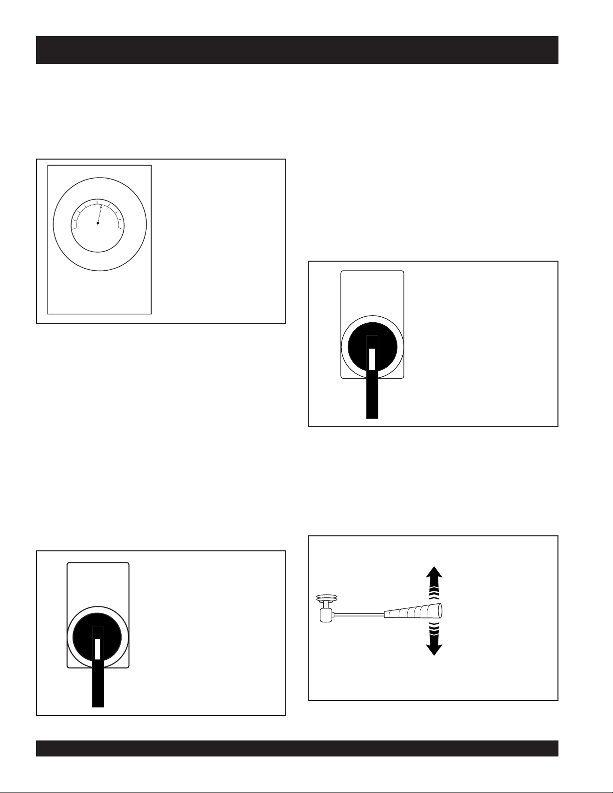
1. To obtain a representative sample, take samples at three or
more regular intervals throughout the discharge of the mixer
or truck. DO NOT take samples at the beginning or end of the
discharge.
2. Dampen the inside of the cone and place it on a smooth,
moist, nonabsorbent, level surface large enough to
accommodate both the slumped concrete and the slump cone.
Stand on the “foot pieces” throughout the test procedure to
hold the cone firmly in place.
!/3
3. Fill the cone
dia x 24" lg. bullet-pointed steel rod. (This is a specific
requirement which will produce non-standard results unless
followed exactly.) Distribute rodding evenly over the entire cross
section of the sample. (See figure A.)
4. Fill cone another
volume. Rod this second layer 25 times with the rod penetrating
into, but not through, the first layer. Distribute rodding evenly
over the entire cross section of the layer. (See figure B.)
5. Fill cone to overflowing. Rod this layer 25 times with rod
penetrating into but not through, the second layer. Distribute
rodding evenly over the entire cross section of this layer. (See
figure C.)
full by volume and rod 25 times with a 1/2"
!/3
which will make the cone
@/3
full by
SLUMP TEST PROCEDURE
6. Remove the excess concrete from the top of the cone, using
the tamping rod as a screed. (See figure D.)
7. Lift the cone vertically with a slow even motion. Do not jar
the concrete or tilt the cone during this process. (See figure
E.) Invert the withdrawn cone, and place it next to, but not
touching the slumped concrete.
8. Lay a straight edge across the top of the slumped cone.
Measure the amount of slump in inches from the bottom of
the straight edge to the top of the slumped concrete at a point
over the original center of the base (See Figure F). The slump
operation must be complete in a maximum elapsed time of 1½ minutes. Discard the concrete. DO NOT use it in any other
tests.
PAGE 18 — ST-70 — PARTS & OPERATION MANUAL — REV. #4 (05/29/07)
Page 19

The following is a brief explanation of
how the concrete cylinders, hydraulic
cylinders, shuttle tube, valves and
hopper work in sequence to pump
concrete.
The hydraulic pressure is generated by
a variable volume, pressure
compensated, axial piston pump that is
driven by a diesel engine. The hydraulic
pressure is applied to one of the two
hydraulic cylinders causing the
hydraulic piston, which is connected to
the concrete piston, to discharge
concrete into the delivery line. The rod
sides of the drive cylinders are
hydraulically connected together
creating a “slave circuit.” As one cylinder
is discharging concrete, the hydraulic oil
from the rod side of the drive cylinders
is being transferred through the slave
circuit causing the opposite cylinder to
move back on the suction stroke filling
the cylinder with concrete. This
operation is made possible by the
shuttle tube located in the hopper and
is sequenced to operate in conjunction
with the cycling of the drive cylinders.
TO TANK
ST-70 — OPERATION (How it Works)
HIGH PRESSURE
OIL FROM PUMP
PROXIMITY
SWITCH
HYDRAULIC
CYLINDERS
A
SLAVE
PROXIMITY SWITCH
OIL
B
PISTON
CUP
CONCRETE
CYLINDERS
SHUTTLE TUBE
A
SLAVE
OIL
B
TO TANK
The ST-70 cycling sequence is initiated
by an electrical signal generated by two
proximity switches located in the drive
cylinder. The proximity switches are
normally open, magnetically sensing the
movement of the main drive cylinder. As
the drive cylinder piston head passes
the proximity switch, an electrical signal
is sent to the solenoid operated pilot
valve which in turn directs pilot oil to the
four valves controlling the drive cylinder
and the shuttle cylinder.
A one-gallon accumulator assists the
movement of the shuttle tube. This circuit
assures that the shuttle tube will throw
with the same intensity of each stroke
regardless of how fast the main drive
cylinders are cycling.
Figure 1
CYLINDER A — INTAKE STROKE
CYLINDER B — DISCHARGE STROKE
Figure 2
CYLINDER A — DISCHARGE STROKE
CYLINDER B — INTAKE STROKE
ST-70 — PARTS & OPERATION MANUAL — REV. #4 (05/29/07) — PAGE 19
Page 20

INITIAL START-UP PROCEDURE
This section is intended to assist the operator with the initial
start-up of the MAYCO ST-70 Concrete Pump. It is extremely
important that this section be read carefully before attempting
to use the pump in the field.
DO NOT proceed to the Operating Procedures (field use) of
this manual until this section is thoroughly understood.
NOTE:
Failure to understand the operation of the MAYCO ST-70
Concrete pump could result in severe damage to the pump or
personal injury.
Figure 1 illustrates the basic operating controls and indicators
on the MAYCO ST-70 Concrete pump. Each of the items
referenced will be discussed. The sequence will be as follows:
1. Engine Oil
2. Hydraulic Oil
3. Fuel
4. Rear Stabilizer Stands
5. Emergency Stop Switch
6. Ignition Switch
7. Status Indicators
8. Control Switch, Engine Throttle Control
9. Volume Control
10. Engine Speed, Cooling Fan
11. Pressure Test
12. Hopper Remixer Control Lever
13. Manual and Radio Control
14. Cylinder Lubrication
Figure 1. MAYCO ST–70
Controls and Indicators
PAGE 20 — ST-70 — PARTS & OPERATION MANUAL — REV. #4 (05/29/07)
Page 21

INITIAL START-UP PROCEDURE
COTTER PIN
BOLT EYE
REAR STABILIZER STAND
HANDLE TEE BOLT
STABILIZER FOOT PAD
Engine Oil
1. Pull the engine oil dipstick from the engine side panel as
shown in Figure 2.
If the hydraulic oil level is low, remove the cap just above
the oil level sight glass and add the correct amount of
hydraulic oil to bring the hydraulic oil level to a normal
safe operating level. (Use Shell oil Tellus 68 or Mobil oil
ENGINE
SIDE PANEL
DFE26)
FUEL
3. Determine if engine fuel is low (Figure 5). If fuel level is
low, remove the fuel filler cap and fill with diesel fuel.
THROTTLE
CABLE
SOLENOID
RED (POSITIVE)
WHITE (NEGATIVE
OIL DIPSTICK
OIL FILTER
Figure 2.
Engine Oil
Determine if engine oil is low. If oil level is low, add correct
amount of engine oil to bring oil level to a normal safe
operating level. See Figure 3.
REAR STABILIZER STAND
Figure 5.
Fuel Sight Tube
To reduce excessive vibration and rocking of the ST-70 Concrete
Pump set the rear stabilizer as follows:
OIL DIPSTICK
ADD ENGINE OIL
SAFE OPERATING
OIL LEVEL
MAX
MIN
Figure 3.
4. Locate both left and right rear stabilizer stands (Figure 6).
Engine Oil Dipstick
Hydraulic Oil
2. Determine if the hydraulic oil level is low by observing the
level of the oil in the Hydraulic Oil Sight Glass (Figure 4).
NORMAL LEVEL
H
I
G
H
L
O
W
150
2
00
100
50
250
0
150
F
HYDRAULIC
OIL LEVEL
SIGHT GLASS
LOW LEVEL
ADD OIL
HYDRAULIC OIL
TEMPERATURE
GAUGE
Figure 4.
A. Remove the
then
B. Position both rear stabilizers stands on firm (not loose)
ground.
C. Align the hole on the stabilizer stand with the hole on the
frame body and
Hydraulic Oil Sight Glass
Figure 6.
Rear Stabilizer Stand
cotter pin
pull
the handle tee to release the stabilizer stand.
from the handle tee bolt eye, and
level
insert
handle tee bolt.
ST-70 — PARTS & OPERATION MANUAL — REV. #4 (05/29/07) — PAGE 21
Page 22
INITIAL START-UP PROCEDURE
D. Insert the cotter pin into handle tee bolt eye to lock the
stabilizer stand.
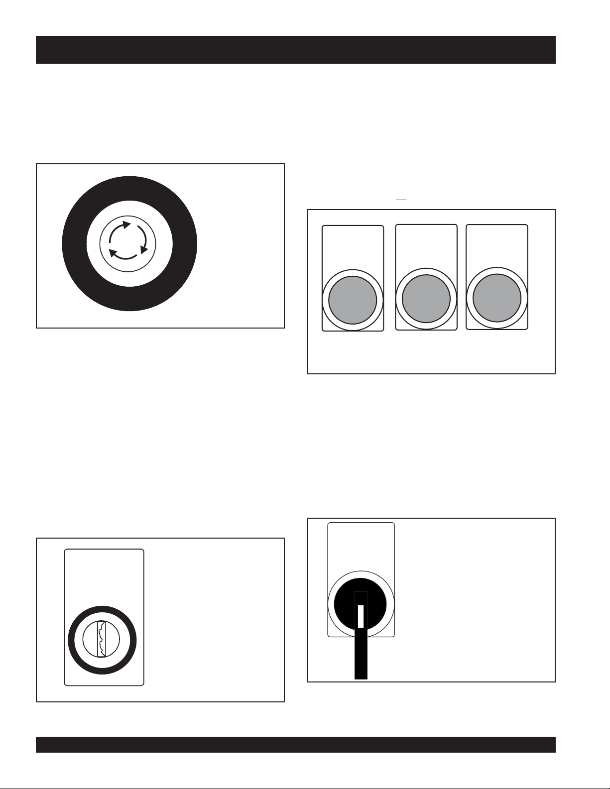
Emergency Stop Switch
5. Locate the Emergency Stop Switch (Figure 7) on the
Hydraulic Pump Control Box. Use this switch in the event of
a emergency.
7. Observe that the Air Filter and Oil Pressure status indicator
lights are ON (Figure 9). The Battery status indicator light
should be OFF
A. Turn the key to the
to start.
B. In warm weather let engine warm-up for 5 minutes. In cold
weather let engine warm-up for 10 minutes.
E
G
N
R
E
M
E
C
Y
S
P
T
O
Emergency Stop
Figure 7.
Switch
C. The Air Filter, Oil Pressure and Battery indicator lights
(Figure 9) should
AIR FILTER
Turn the Emergency Stop switch counter-clockwise (open).
This will allow the engine to start.
NOTE:
If the Emergency Stop switch is in the closed position (stop),
engine will not start. To start the engine, make sure the
Emergency Stop switch is in the open position (fully extended).
NOTE:
If any of the status indicator lights referenced in the ignition
section (step 4) are ON, turn off the engine. DO NOT continue
to run the engine.
Ignition Switch
NOTE:
Place all switches on the Hydraulic Control Box in the vertical
position (up).
6. To start the engine, insert the key (Figure 8) into the ignition
Control Switch
8. Turn the Control Off switch (Figure 10) to the ON position,
thumping
a
thumping sound represents the number of strokes per
minute (volume) of the pump.
switch and turn the key to the ON position.
IGNITION
ON
CONTROL
OFF
REMOTE
START
position and listen for the engine
all be off.
OIL
PRESSURE
Status indicator Lights
BATTERY
Figure 9.
sound (cylinder stroke) should be heard. The
OFF
ON
START
Figure 8.
Ignition Switch
Control Off Switch
PAGE 22 — ST-70 — PARTS & OPERATION MANUAL — REV. #4 (05/29/07)
Figure 10.
Page 23
0
0 0
0
4
THROTTLE
CONTROL
TURN CLOCKWISE TO
INCREASE ENGINE SPEED
TURN COUNTER CLOCKWISE
TO DECREASE ENGINE SPEED
INITIAL START-UP PROCEDURE
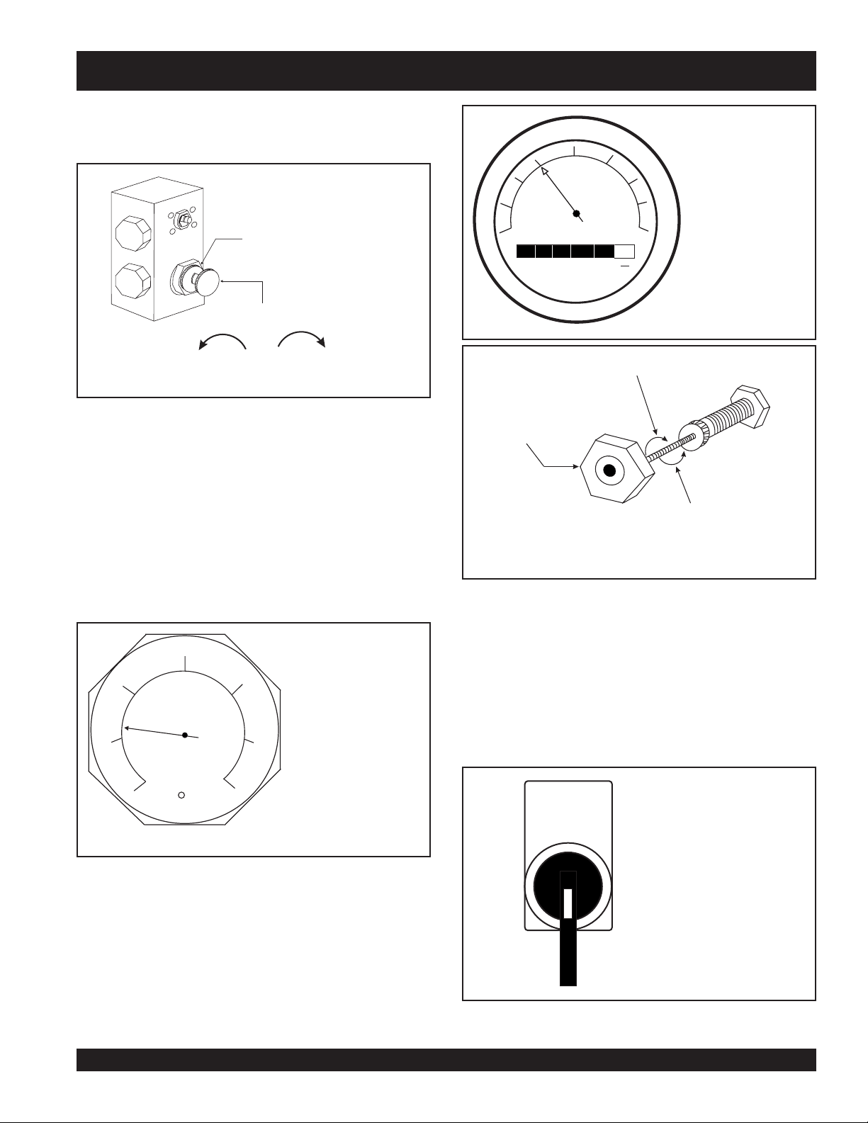
9. Turn the Volume Control (Figure 11),
lock nut
counterclockwise (CCW) to release the volume control
knob.
5
3C
3A
VOLUME CONTROL
LOCK NUT
VOLUME CONTROL
CCW
CW
DECREASEINCREASE
0
Figure 11.
Volume Control
A. Use the volume control, to set the pump volume to
approximately 10 strokes per minute. Turning the volume
control clockwise (CW) will
counterclockwise (CCW) will
decrease
increase pump
pump volume, and
volume.
NOTE:
15
20
RPM X 100
TACH
HOURS
25
3010
35
40
8
1
10
Figure 13.
Engine Tachometer
Use a wristwatch or stop watch to determine the number of
pump strokes within 1 minute.
B. Let the pump cycle until the hydraulic oil temperature
C. While monitoring the tachometer, (Figure 13) turn the
(Figure 12) is approximately 50 to 60 degrees fahrenheit.
D. Turn the Control Off switch (Figure 10) to the OFF position.
Engine Speed
150
200
100
10. Turn the Operation Pump/Engine switch to the
NOTE:
The pump should not be cycling at this time. Only the ENGINE
50
250
0
150
should be running.
F
Figure 12. Hydraulic Oil
Temperature Gauge
engine Throttle Control (Figure 14) until the engine speed
reaches 1500 RPM.
ST-70 — PARTS & OPERATION MANUAL — REV. #4 (05/29/07) — PAGE 23
Figure 14.
Engine Throttle Control
engine
position (Figure 15).
OPERATION
PUMP
ENGINE
Figure 15. Operation
Pump/Engine Switch
Page 24
INITIAL START-UP PROCEDURE
A. While monitoring the tachometer, (Figure 13) turn the
engine Throttle Control (Figure 14) clockwise until the
engine speed reaches 2550 RPM (maximum speed).
B. The Accumulator Pressure Gauge (Figure 16) should read
approximately 1750 pounds per square inch (psi).
Turn the Fan switch to the OFF position and listen for fan to
stop. If machine exceeds 170°F, and to cool the machine down,
turn operation switch to (Fig. 15) engine position. Run engine at
high RPM with cooling fan on for 10 to 15 minutes.
NOTE: Do not stroke cylinders. The operator may also spray
the hydraulic tank and components with water.
PRESSURE TEST
12. The Pressure Test switch (Figure 18) is a self-diagnostic
test switch, that when activated will test the pressure of the
system. This switch will be discussed in the maintenance
500
1500
1
0
0
0
0
LHA
2000
2500
3000
and troubleshooting section of this manual.
ACCUMULATOR
PRESSURE GAUGE
0-3000 PSI
Figure 16. Accumulator
Pressure Gauge
11. COOLING FAN
CAUTION
If the hydraulic oil temperature exceeds 170 degrees fahrenheit,
shut down the pump. DO NOT continue to operate the pump.
Failure to shut down the pump will result in severe damage to
the pump.
This section is intended to make sure the Fan is working properly.
Under normal conditions the Fan should be turned on when the
hydraulic oil temperature begins to approach between 75
degrees fahrenheit.
Make sure the Operation Pump/Engine switch is in the
engine
position (Figure 15), and that only the engine is running.
Turn the Fan switch (Figure 17) to the ON position and listen for
13. HOPPER REMIXER CONTROL
A. Located to the left of the Hydraulic Temperature gauge is
the Hopper Remixer Control lever (Figure 19).
B. Turn the Operation Pump/Engine switch to the engine
position (only the engine should be running).
fan to start.
PRESS TEST
OFF
ON
Figure 18.
Pressure Test On/Off Switch
PUSH UP TO
REVERSE BLADE
ROTATION (CCW)
FAN
OFF
ON
PUSH DOWN
Figure 17.
TO OPERATE
(CW BLADE
ROTATION)
Hopper Remixer
Control Lever
Fan On/Off Switch
PAGE 24 — ST-70 — PARTS & OPERATION MANUAL — REV. #4 (05/29/07)
Figure 19.
Page 25
INITIAL START-UP PROCEDURE
ON
ON
OFF
OFF
A B
HANDHELD
REMOTE CONTROL TRANSMITTER
REMOTE CONTROL RECEIVER
ANTENNA
INPUT
CONTROL SWITCHES
MOUNT ON MAYCO ST-45
FRAME
BODY
SIGNAL
CABLE
HAND HELD
REMOTE
UNIT
CONTROL SWITCHES
25 FT. CABLE
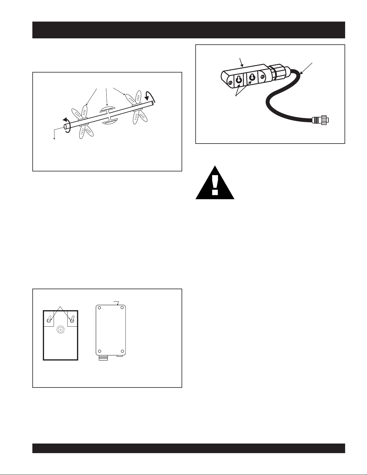
C. Push the Hopper Remixer Control lever
downward
(Figure
19) and observe that the blades (Figure 20) inside the
hopper are turning in a clockwise direction (forward).
BLADES
CONTROL SWITCHES
FORWARD
REVERSE
(CCW)
SHAFT ROTATION
(CW)
Figure 20.
Hopper Remixer
15. CYLINDER LUBRICATION BOX
Blades (Rotation)
D. Push the Hopper Remixer Control lever
upward
(Figure
18) and observe that the blades (Figure 20) inside the
hopper are turning in a counter-clockwise direction
(reverse).
everyday prior to pumping. The oil level should be maintained
at a height of 5 inches or about ´½ the concrete cylinder height.
14. OPTIONAL RADIO REMOTE CONTROL
The MAYCO ST-70 Concrete Pump has a remote control feature
that allows the pump to be remotely controlled. If desired, the
pump can be operated via a receiver/transmitter method (Figure
21) or a hardwire method, which utilizes a 25-ft. extension cable.
The manual remote cord (Figure 22) should be installed under
the main control box. Contact your MAYCO representative for
further information.
Important Notice! During freezing temperature after pumping,
completely drain the water box and cover the hopper. Frozen
liquid will restrict the piston travel and cause severe damage to
the pump.
As the rubber piston cups naturally wear, fine cement particles
will accumulate in the box. Once the concrete paste reaches a
height of about ½ inch from the bottom. The box should be
drained and cleaned. To clean, remove the drain plug located
at the bottom of the box. Once the Box is drained, start the
CONTROL SWITCHES
MOUNT ON MAYCO ST-45
FRAME BODY
engine and stroke the cylinder (keep hands out of box) ten to
fifteen times. While stroking, spray water inside of the box to
thoroughly clean out all contamination. When the box is clean,
replace drain plug, add new lubrication and install the top cover.
REMTRON
REMOTE CONTROL TRANSMITTER
REMOTE CONTROL RECEIVER
REMTRON
Any questions regarding the above mentioned procedure,
please call the Mayco Service Department: 1-800-30-MAYCO.
HAND HELD
REMOTE UNIT
25 FT. CABLE
Figure 22.
Handheld Remote Cable Unit
WARNING
Before checking lubricaton level, stop the
engine and remove the engine starter key. We
recommend using soluble type oil (water & oil
mixture). The oil level should be checked
SIGNAL
ANTENNA
INPUT
CABLE
Figure 21.
Handheld Receiver/
Transmitter
ST-70 — PARTS & OPERATION MANUAL — REV. #4 (05/29/07) — PAGE 25
Page 26

ST-70 — OPERATING PROCEDURES
Important Rules for the Setup and Operation of
Mayco Model ST-70 Hydraulic Concrete Pump
1. The Mayco pump must be operated by experienced
operators, who are qualified with the particular model being
used, or students under the direct supervision of an
experienced operator. The operator is in complete charge
of the pump and delivery system. Know and warn all others
of the DANGERS that are present when using, maintaining
or being around this pump and delivery system. KNOW
YOUR MACHINE!
2. The operator must become familiar with the controls and
gauges by a careful study of the owners manual.
3. The operator must become aware and understand the
danger involved in the operation and maintenance of the
pump.
4. The operator must know the limitation of the pump described
in this manual.
5. The concrete pump is capable of developing high pressures
on the concrete. Proper care must be used in the
maintenance of pipes and hoses and hose couplings for
safe operation.
6. Only experienced operators, or students under the direct
supervision of an experienced operator shall perform any
maintenance, cleaning, repair or setup operations.
7. Unauthorized persons must not be permitted to assist or
remain in the immediate vicinity of the unit while it is in
operation.
8. The Mayco pump must not be operated by individuals who
cannot read and understand the owners manual in the
language in which it is printed.
9. The Mayco pump must not be operated by anyone under
the age of 18 years.
10. The Mayco pump must not be operated by anyone under
the influence of alcohol or drugs.
11. Locate the pump in an area as level as possible, where two
or more ready-mix trucks will have access to the hopper.
12. Begin pumping by placing the hoses or pipe at the farthest
point of discharge.
13. Concrete will flow with less back pressure through pipe
than through hose. Bends in hose or pipe will also require
more pressure. The operator should take these facts into
consideration when laying out the system.
14. Vertical and down-hill pumping are more difficult than
horizontal pumping. Vertical pumping requires higher
pumping pressure. Down-hill pumping can cause
separation of the concrete, which can cause a blockage.
Back pressure must be kept in the line at all times during
down-hill pumping.
15. When the pump is parked in the street, position it so that the
control panel (right side) is closest to the curb. – ALWAYS
THINK SAFETY!
16. Lower and lock the rear jackstands in place before any
concrete is discharged into the hopper.
17. THE DELIVERY SYSTEM
To successfully pump concrete it is critical to use the correct
size and type of delivery system.
The rules that govern the size of the delivery system apply
to all concrete pumps, not just Mayco pumps.
The inside diameter of the hose and pipe must be three to
four (3 to 4) times the size of the largest aggregate in the mix
that is to be pumped.
The rock size and percentage shown is of the total rock content
in the mix. The balance of the rock must be properly blended
down through all of the smaller sizes.
The same applies to the sand portion of the mix.
Consult the ready-mix company and ensure that they are willing
and able to deliver properly blended aggregates in their
concrete. 3" inside diameter is the smallest system of hose,
pipe and elbows that is recommended for pumping “Hard Rock”,
large aggregate concrete.
Remember – The larger the size of the delivery system, the less
pressure required to move the concrete.
Use this information in conjunction with “Concrete Mix Design”
on pages 12 thru 17.
Example:
1-1/2" rock (8 to 10% max. content by weight) requires
a 5" dia. concrete delivery system.
1" rock (10 to 15% max. content by weight) requires a
4" dia. concrete delivery system.
¾" and under rock (10 to 15% max. content by weight)
requires a 3" dia. concrete delivery system.
PAGE 26 — ST-70 — PARTS & OPERATION MANUAL — REV. #4 (05/29/07)
Page 27

ST-70 — OPERATING PROCEDURES
18 Priming the Pump and Delivery System with Slurry.
It is CRITICAL to the successful operation of a concrete
pump that the manifold and all delivery hose, pipe and
elbows are coated with a film of lubrication BEFORE
you attempt to pump concrete. Failure to properly
prepare the pump and system will result in a “dry pack”
of concrete, blocking the shuttle valve tube or delivery
line.
18.1 With the entire delivery system connected to the pump.
Except for the first hose. Pour 5 gallons of water into the
second hose and push in your clean out ball and
reconnect. This will help hold back the prime.
18.2 What you can use to mix the prime:
There are several things you can use for the prime. Here
are a few. Cement and lime at a 50/50 mixture, slick pac,
bentonite clay.
NOTE: The bentonite is not compatible with concrete.
Do not pump it into the forms discharge it out of the
formed area.
Mix the prime to the consistency of a smooth batter.
18.4 Position the first ready-mix truck at the hopper. Check
the concrete. Do not discharge concrete into hopper at
this time.
18.5 Pour the prime into the first hose and connect it to the
pump.
NOTE: You should use two 5 gallon buckets of prime.
19. Waiting for concrete trucks to arrive: If there are delays:
19.1 Stop the pump with a full hopper.
19.2 Run the remixer, alternating forward and reverse,
19.3 Add water to stiff mixes, if necessary.
19.4 If shutdown period exceeds 3 to 4 minutes, turn off engine
19.5 Start the engine, cycle the pump slowly 1 or 2 strokes
19.6 If shutdown period reaches 1 hour (or less, depending
to push through blockages due to separation of material in the
hose or manifold, you will soon have breakdowns and costly
repairs which are not covered under the warranty. If a blockage
exists, find where it is and clear it before further pumping. Do
not use extra horse power, it will only make it worse.
whenever the engine is running.
to prevent vibration from separating the mix in the hopper.
Separation will cause a blockage in the manifold when
pumping is resumed.
and run remixer every 10 minutes.
on the age and temperature of the concrete), pump out
and clean the delivery system and pump. (See page
24 for clean up procedures.)
WARNING: Common sense tells us that if you
drive a truck into a “brick wall,” something is
going to be damaged. The same holds true
with your concrete pump. If you repeatedly pull
the throttle all the way out and force your pump
18.6 With the pump in FORWARD at 25-30 strokes per minute,
slowly discharge the concrete from the ready-mix truck
into the hopper and completely fill it. Keep the pump
running continuously until concrete is discharging at
the end of the delivery system. If the pump is stopped
during this procedure, a blockage may occur (see page
22, Section 4).
18.7 If it is necessary to replace or add a section of delivery
system, after the initial lubrication procedure, wet the
inside area of the hose, pipe or elbow with 5 gallons of
water per 25 foot length, before adding it to the
system.
1. When pumping long distances or pumping stiff mixes, you
2. Leaking hose coupling gaskets (which leak water) cause
ST-70 — PARTS & OPERATION MANUAL — REV. #4 (05/29/07) — PAGE 27
can expect a drop in volume, compared to shorter lines and
wetter mixes due to higher pumping pressures and
cavitation.
separation and subsequent jamming at that point.
Page 28

ST-70 — OPERATING PROCEDURES
3. Damaged hoses with internal restrictions can cause
blockages.
4. If a blockage occurs in the hose, STOP the pump, “walk the
hose” until you find the point of trouble. (The hose will be
soft immediately past the blockage.) Elevate the hose at
that point with the blockage hanging down. Using a hammer,
you can pound the down stream edge of the packed area
until it free flows or shakes out of the hose. Pumping can
now be resumed. If this method does not clear the pack
FOLLOW THE INSTRUCTIONS IN Section 7, paragraph
7.1 thru 7.5 of this page.
5. “Down-hill pumping” can be difficult. When the pump is
stopped, the material can flow slowly and cause the hose to
collapse. When pumping is resumed, you can expect a
blockage at the point of hose collapse. To prevent this, the
hose can be “kinked off” at the discharge end when the
pump is stopped, to stop gravity flow. The use of stiffer mixes
when pumping down-hill will stop gravity flow.
6. When pumping vertically:
6.1 When pumping vertically up the side of a building,
above 40 feet, we recommend the installation of steel pipe
securely fastened at intervals as necessary to support the
pipe. Ninety-degree, long-radius pipe sweeps should be
installed at the top and bottom of the steel line. Use a 25 ft.
hose, or short section, off the pump. For the balance of the
horizontal distance to the vertical line, use pipe. This type of
installation has been satisfactory on many jobs being
pumped in excess of 100 feet high. Line pressures are
always less using steel pipe as compared to hose.
6.2 When pumping vertically using all hose, it is
recommended not to go higher than 50 feet with hose. The
hose should be tied off at intervals of 10 feet, if possible.
Special attention should be given when tying the hose off at
the top as the hose will have a tendency to stretch when
filled with concrete. This will increase the possibility of a
blockage at the point where the hose is tied off. To avoid
this, a long radius 90 degree elbow is recommended. The
suggested place to tie off is under the clamp coupling that
connects the hose to the 90 degree elbow.
Note: It is strongly recommended that pipe be used
on all vertical pumping for safety and convenience. If
it is absolutely necessary to use hose, then use
section 6.2 as a guide.
7. The shuttle tube is plugged if volume at the discharge end
of the hose stops, the hose is soft and the hydraulic oil
pressure gauge reads 3000 psi or more.
To clear a plug in the shuttle tube, great care must be taken
as a dangerous condition will exist from pressure build-up
inside the shuttle tube. (With the shuttle valve, the concrete
can be pumped in reverse.)
Follow these instructions carefully:
7.1 DO NOT open any of the delivery system joint clamps.
7.2 Switch the pump into “Reverse”:
With pump speed at medium-slow (approx. 12 strokes per
min.) try to pull the “pack” back into the hopper with 5 or 6
reverse strokes, remix the concrete in the hopper.
Switch the pump into “Forward”.
If it is still plugged, repeat “Reversing” procedure three
times.
If concrete still does not move, see 7.3 and 7.4 below. The
last action MUST be “pumping in reverse” to relieve the
pressure in the shuttle tube.
7.3 Stop the pump. Switch off the engine.
7.4 The senior or most experienced operator must warn all
others to stand at least 20 feet away from the machine and
turn their heads to face away from the pump.
The operator will position himself/herself beside the
reducing elbow at the pump outlet, then, wearing safety
glasses slip the end of a pry bar (24" length of reinforcing
steel rod) under the latch of the hose clamp and flip it up.
Carefully knock the end of the hose away from the reducer.
Chip the concrete out of the reducer with the pry bar.
Remove the reducer.
From the discharge end chip the concrete out of the shuttle
tube with the pry-bar. If concrete cannot be loosened from
the outlet of the shuttle tube, then remove the clean-out plug
on the bottom of the hopper, discharging the concrete.
Only the senior operator may then remove the inspection
cover plate from the shuttle tube, by using a long extension
wrench and the 24" pry bar. Make sure the accumulator
pressure gauge reads zero prior to removing cover.
WARNING: NEVER PLACE YOUR HANDS
OR ANY PART OF YOUR BODY IN THE
HOPPER OR ALLOW ANYONE ELSE TO DO
SO.
PAGE 28 — ST-70 — PARTS & OPERATION MANUAL — REV. #4 (05/29/07)
Page 29

ST-70 — OPERATING PROCEDURES
Chip the blockage out with the pry-bar.
Flush the shuttle tube with water.
Replace and seal the inspection cover plate on the shuttle
tube.
7.5 Resume pumping.
8. The effects of heat and excessive time on concrete:
Hot concrete, commonly referred to as a “hot load”, is
concrete that has been in a redi-mix truck in excess of 2 to
3 hours. On a hot day, the amount of time is even less. A
brief explanation of why heat and time affect concrete:
Concrete starts setting or drying up through a chemical
reaction. The catalyst to this reaction is heat. When pumping
a hot load, it is important to remember that when you have
to stop pumping for any reason, add water to the concrete in
the hopper and remix (see Page 27, Section 19). Move
concrete in the hose every 5 minutes. If shutdown time
becomes too long, wash out immediately (see Page 24).
9. ADMIXTURES: Admixtures are designed into the concrete
mix by the redi-mix company or an architectural engineering
company. This section lists common admixtures and a brief
explanation of their function.
9.1 POZZOLITH 300 R or the equivalent. – Acts as a water
retarder and a lubricant. On a lean mix, long pushes stiff
mixes and vertical pushes, Pozzolith 300 R helps
pumpability.
10. If the volume at end of hose starts to decrease gradually
and eventually almost stops, it is quite likely that the wear
ring and/or wear plate have to be replaced due to
excessive wear allowing the concrete to be discharged
back into the hopper under pressure. This is a major reason
for plugging in the shuttle tube.
11. Slight pulsation of the hose will always be noticeable near
the pump. Excessive pulsation of the hose near the pump
is normally due to higher than average line pressures
caused by stiff, harsh mixes or extremely long pumping
distances. The use of larger I.D. hose than specified on
page 3-8, para. 17 in these extreme cases reduces line
pressures or the addition of slight amounts of water to the
mix, if permissible, will permit easier pumping. The use of
certain pumping admixtures may help. If excessive
pulsation exists, it is advisable to use burlap or some
means of protection under the hose at points where the
hose may wear through the outer cover; e.g., over forms
or steel or sharp curbs.
12. It is the responsibility of the pump operator to ensure that
the delivery system hose and line system, with all clamps
and accessories have a higher pressure rating than the
concrete pump can generate. The model ST-70 generates
875 p.s.i.
13. Before starting the pumping operation, the following check
list procedure should be followed:
9.2 MBVR – Air entraining, acts as a lubricant.
9.3 CALCIUM CHLORIDE – Commonly referred to as C.C. , is
used as an accelerator. When pumping a load with calcium
chloride, it is recommended that you wash out if the waiting
time between delivery trucks becomes too long.
9.4 SUPER PLASTICIZERS – Acts as an accelerator. The
concrete will look very wet after the super plasticizer is
added, but will begin to set up very fast. Wash out
immediately if you do not have a truck waiting. Super
plasticizers are used mainly on commercial jobs.
9.5 RED LABEL – Acts as water retarder and an accelerator.
Red label also will mainly be used on commercial jobs.
9.6 FLY ASH – Is used to help increase the strength of the
concrete and decrease the cement content per yard. This is
one of the most common admixtures used.
NOTE: All admixtures will be shown on the redi-mix concrete
ticket. It is suggested before starting the pumping job you ask
the driver of the redi-mix truck to see the concrete ticket and
note the admixtures that exist and take the proper action.
13.1 Check engine oil.
13.2 Check oil reservoir to make sure that it is full.
13.3 Start and run the engine a minimum of five minutes
13.4 Cycle the pump at 6 strokes/minute maximum and
NOTE: When the redi-mix truck arrives, it is always a good idea
to check the concrete ticket and make sure you have the proper
mix design. When adding water to the mix, be sure not to get the
concrete too wet. In other words, if you think the load of concrete
needs 40 gallons, put in 20 gallons. You can always add more
water to the load but you cannot extract the water from the load.
before starting the pumping operation.
warm oil to 50 degrees Fahrenheit.
ST-70 — PARTS & OPERATION MANUAL — REV. #4 (05/29/07) — PAGE 29
Page 30

ST-70 — OPERATING PROCEDURES
14. All new pumps are ‘water pressure tested” at the factory
This procedure permits a thorough inspection of entire
drive system and valving under simulated full load
conditions. The pump owner can do the same by making
an adapter to couple to the end of the discharge cone:
#/8
#/8
" diameter
" drilled
e.g., the use of a standard 2" pipe cap with a
hole in the center, screwed on to the end of hinged cone
or reducer at the pump. Fill hopper with water after making
sure that all sand and rock have been removed from
manifold. Operate pump at full throttle and the
hole restriction will create sufficient back pressure to make
thorough inspection of all moving parts.
CLEANING THE PUMP AND DELIVERY SYSTEM
Cleaning the pump is a very important operation as it
determines how the machine will
pump the next time it is used.
At the end of every pour, or because of long delays during a
pour, the pump and delivery system must be thoroughly cleaned
by removing all concrete material.
1. Ensure that there is no blockage in the hose and line (See
page 29, Section 4) or in the shuttle tube (See Page 29,
Section 7). If a blockage exists, clear it.
2. Pump concrete until the opening of the concrete cylinder
intake in the hopper is visible.
3. Stop the pump.
4. Carefully disconnect the first hose joint at the shuttle tube
discharge elbow.
7. Fill hopper with water. Pump until sponge and clean water
come out the discharge end of the hose and line system.
8. When the Model ST-70 has been used to pump small
aggregate concrete (pea rock, ½" minus) or mixes with
high fines content (60% or more sand) there will be a
tendency for hardened concrete to build up on the inside
surface of the shuttle tube. Therefore, at the end of every
such pour, after the pump and system have been cleaned
and the engine shut off, remove the shuttle tube inspection
plate (See Page 28, Section 7.4) and remove all remaining
concrete.
9. When the Model ST-70 has been used to pump large
aggregate concrete (¾" to 1 ½") follow the instructions in the
above Section 8 once per week.
WARNING
Use only a 2½" diameter clean-out hook when backpumping into redi-mix truck. Use a safety chain to secure
the clean-out hook to some solid part of the mixer truck to
prevent hook from jumping off of the drum.
Run the pump at 6 strokes per minute maximum speed.
NEVER put your hands or any other parts of
your body in the hopper while the engine is
running or prior to any maintenance, check
the accumulator pressure gauge and make
sure the reading is zero pressure.
NEVER use muriatic acid to clean the pump.
Acid will dissolve the chrome finish on
material cylinder bore and main hydraulic
cylinder rods.
5. Add water to the hopper. Pump and flush clean the entire
hopper, shuttle tube and discharge elbow with water.
6. Scoop out 12 inches of concrete from the inboard end of the
delivery hose. “Cork screw” a 6" x 6" x 8" sponge into the
end of the first hose section. Reconnect the hose to the
discharge elbow.
PAGE 30 — ST-70 — PARTS & OPERATION MANUAL — REV. #4 (05/29/07)
Page 31

ST-70 — TOWING INFORMATION
1. Position actuator ball socket above 2" ball.
WARNING: Use jack stand to lift tongue. Do
hand as back injury could result.
CAUTION:
The ball capacity must be greater than or equal
to the trailer GVWR. Do not use a worn hitch
ball, it is unsafe and must be replaced. USE 2"
BALL ONLY
NOTE:
Take care not to damage the actuator when backing up the
towing vehicle for hook-up.
2. Hold the release handle in the open position (Figure 1).
NOT lift by
5. To make sure that the actuator is securely latched onto the
6. Insert a padlock or bolt through the lock hole for added
7. Connect the breakaway cable solidly to the bumper or frame
8. Make sure the breakaway cable is in a released position
ball, extend the trailer tongue jack to the ground and lift the
truck and trailer combination 2" to 4". If the ball does not
disengage, the actuator is securely attached.
protection.
of the tow vehicle as near to the center as possible. The
cable must hang clear of the trailer tongue and be long
enough to permit short radius turns without pulling the
breakaway cable forward.
with the indicator bead touching or resting against the cable
spring stop. (Figure 2).
CAUTION:
NOTE:
Fig. 1
3. Lower the trailer tongue until the ball rests in the ball socket.
4. Close the release handle.
CAUTION:
The release handle will close freely with
finger pressure when the ball is properly
inserted into ball socket. If the release handle
does not close freely, do not tow the trailer. Do
not force the release handle into the closed
position.
Check the location of the breakaway cable periodically
during each trip. The indicator should rest against the spring
stop. Accidental application will cause the brakes to drag
and heat up, causing a failure.
9. Cross the safety chains under the tongue and securely
attach them to the bumper or frame of the tow vehicle. Check
with local and state laws for proper compliance.
CAUTION:
Fig. 2
Do not use the breakaway cable as a parking
brake.
Safety chains must always be used.
ST-70 — PARTS & OPERATION MANUAL — REV. #4 (05/29/07) — PAGE 31
Page 32

ST-70 — TOWING INFORMATION
10. Retract the jack fully. Remove and store the caster, if
applicable.
11. Check for proper truck-trailer hook-up; the tow vehicle and
trailer should be level with a positive tongue load. For further
information, consult a dealer or Atwood Service Center.
12. The back-up lever knob must be positioned in the “Towing
Position” (Figure 3).
Fig. 3
BACKING UP
1. Refer to the previous steps 1 through 14 for Towing.
2. Before backing up a slope or through soft ground, pull the
trailer forward slightly to assure that the actuator socket is
in the fully forward position.
3. Move the lever knob on the side of the actuator downward
from the “Towing Position” along the curved slot in the
actuator frame to the “Back-up Position” (Figure 3). The
slot has a notch at the bottom of its travel. Push the lever
knob down to engage the locking notch.
4. Back the trailer up.
CAUTION:
Avoid sharp turns. This could bend, create
extreme stress or fracture either the actuator
or trailer tongue.
13.Do not use the Atwood brake actuator with a sway
controller, unless prior Atwood Engineering approval of the
sway control system has been received.
14. You are now ready to tow your pump.
CAUTION:
Avoid sharp turns. This could bend, create
extreme stress or fracture either the actuator
or trailer tongue.
PAGE 32 — ST-70 — PARTS & OPERATION MANUAL — REV. #4 (05/29/07)
Page 33

ST-70 — TOWING INFORMATION
5. If the pump is to be uncoupled from the tow vehicle after
backing with the lever knob engaged, block all pump wheels
and pull forward slightly to take strain off of the actuator.
Uncouple the actuator by lifting the release handle and
raising the trailer tongue. Make sure the lever knob is in the
“Towing Position” when uncoupling from the trailer.
CAUTION:
Before towing the pump, always ensure that
the lever knob has disengaged and is in the
“Towing Position.”
MAINTENANCE
1. Keep all links and pivots lubricated to prevent rusting and
ensure ease of operation. Using SAE 30 oil, lubricate inside
the release handle and inside the actuator body. This can
be reached from the underside of the actuator.
NOTE:
Lubricate the hitch ball with conventional automotive
grease or a lubricant made for hitch balls.
Extended Storage Instructions
The following preventative maintenance is recommended for
extended periods of storage.
1. Check brake system for proper fluid level in master cylinder
and bleed all lines.
2. Lubricate all links and pivots to prevent any rusting.
3. Remove wheel and drum assemblies and spray a good
anti-corrosion compound (CRC formula 5-56) under rubber
boot on forward end of brake wheel cylinder. Avoid spraying
drum and brake lining.
4. Grease all bearings and reinstall wheel and drum
assemblies.
5. Make sure breakaway cable is fully released.
6. After extended storage, refer to the Maintenance Steps
listed above to insure that the trailer is ready for towing.
2. Check for any leaks in the brake system. Periodic checks
should be made on all hoses to guard against cuts and
worn hoses which may cause failure (leaks, rupturing
under pressure, and collapsing). Replace defective hoses.
3. Check the brake fluid level in the master cylinder reservoir.
Keep it filled to within ½" from the top of the reservoir.
CAUTION:
Do not fill the master cylinder reservoir with
used brake fluid. Do not fill the reservoir
beyond ½" from top. Do not overfill, brake fluid
will damage paint.
4. At the beginning of each year, inspect the brakes for
excessive wear, replace the linings if necessary.
NOTE:
Wheel bearings and seals should be inspected and packed
at this time.
ST-70 — PARTS & OPERATION MANUAL — REV. #4 (05/29/07) — PAGE 33
Page 34

EXPLANATION OF CODE IN REMARKS COLUMN
The following section explains the different symbols and remarks
used in the Parts section of this manual. Use the help numbers
found on the back page of the manual if there are any questions.
The contents and part numbers listed in the parts section are
subject to change
guarantee the availibility of the parts listed.
Sample Parts List:
NO. PART NO. PART NAME QTY. REMARKS
1 12345 BOLT ....................... 1.... INCLUDES ITEMS W/
2
*
2*12347 WASHER, 3/8 IN. .... 1 ....
3 12348 HOSE .................... A/R .. MAKE LOCALLY
4 12349 BEARING ................ 1 .... S/N 2345B AND ABOVE
NO. Column
Unique Symbols - All items with same unique symbol
, #, +, %, or >) in the number column belong to the same
(
*
assembly or kit, which is indicated by a note in the “Remarks”
column.
Duplicate Item Numbers - Duplicate numbers indicate
multiple part numbers are in effect for the same general item,
such as different size saw blade guards in use or a part that
has been updated on newer versions of the same machine.
NOTE
without notice
WASHER, 1/4 IN. ...........
When ordering a part that has more
than one item number listed, check
the remarks column for help in
determining the proper part to order.
. Multiquip does not
NOT SOLD SEPARATELY
MQ-45T ONLY
QTY. Column
Numbers Used - Item quantity can be indicated by a number,
a blank entry, or A/R.
A/R (As Required) is generally used for hoses or other parts
that are sold in bulk and cut to length.
A blank entry generally indicates that the item is not sold
separately. Other entries will be clarified in the “Remarks”
Column.
REMARKS Column
Some of the most common notes found in the “Remarks”
*
Column are listed below. Other additional notes needed to
describe the item can also be shown.
Assembly/Kit
symbol will be included when this item is purchased.
Indicated by:
“INCLUDES ITEMS W/(unique symbol)”
Serial Number Break
range where a particular part is used.
Indicated by:
“S/N XXXXX AND BELOW”
“S/N XXXX AND ABOVE”
“S/N XXXX TO S/N XXX”
Specific Model Number Use
only with the specific model number or model number variant
listed. It can also be used to show a part is NOT used on a
specific model or model number variant.
Indicated by:
“XXXXX ONLY”
“NOT USED ON XXXX”
- All items on the parts list with the same unique
- Used to list an effective serial number
- Indicates that the part is used
PART NO. Column
Numbers Used - Part numbers can be indicated by a number,
a blank entry, or TBD.
TBD (To Be Determined) is generally used to show a part that
has not been assigned a formal part number at time of
publication.
A blank entry generally indicates that the item is not sold
separately or is not sold by Multiquip. Other entries will be
clarified in the “Remarks” Column.
PAGE 34 — ST-70 — PARTS & OPERATION MANUAL — REV. #4 (05/29/07)
“Make/Obtain Locally”
purchased at any hardware shop or made out of available
items. Examples include battery cables, shims, and certain
washers and nuts.
“Not Sold Separately”
purchased as a separate item and is either part of an
assembly/kit that can be purchased, or is not available for
sale through Multiquip.
- Indicates that the part can be
- Indicates that an item cannot be
Page 35

ST-70 — SUGGESTED SPARE PARTS
ST-70 Structural Concrete Pump
1 Units
Qty. P/N Description
1 .......... EM16462 .............. FELT HOLDER
4 .......... EM16463 .............. PISTON CUP
4 .......... EM16493 .............. FELT RING
1 .......... EM16461 .............. OIL PARTS
2 .......... EM14408 .............. BRONZE RING
2 .......... EM16145 .............. BUSHING, SWING AXLE (BRONZE )
1 .......... EM16171 .............. WEAR RING
2 .......... EM16816-1 ........... ENERGIZER RING
1 .......... EM16816-2 ........... INSERT RING
2 .......... EM16819 .............. SLEEVE SEAL
1 .......... EM25841 .............. WEAR PLATE
2 .......... EM97024 .............. SWITCH, PROXIMITY
1 .......... EM50417 .............. CUP
1 .......... EM20709-1 ........... SOLENOID
2 .......... EM97050 .............. RELAY (IDEC)
1 .......... EM97048 .............. RELAY
1 .......... EM97021 .............. SOLENOID
1 .......... EM97036 .............. SWITCH, PUMP CONTROL
1 .......... EM97045 .............. SWITCH, OPERATION PUMP/ENG
ST-70 Structural Concrete Pump
3 Units
Qty. P/N Description
1 .......... EM16459 .............. PIN
2 .......... EM25801 .............. CONCRETE CYLINDER
2 .......... EM16462 .............. FELT HOLDER
6 .......... EM16463 .............. PISTON CUP
8 .......... EM16493 .............. FELT RING
2 .......... EM16461 .............. OIL PARTS
2 .......... EM14408 .............. BRONZE RING
4 .......... EM16145 .............. BUSHING, SWING AXLE (BRONZE )
3 .......... EM16171 .............. WEAR RING
4 .......... EM16816-1 ........... ENERGIZER RING
2 .......... EM16816-2 ........... INSERT RING
4 .......... EM16819 .............. SLEEVE SEAL
2 .......... EM25841 .............. WEAR PLATE
4 .......... EM97024 .............. SWITCH, PROXIMITY
3 .......... EM50417 .............. CUP
2 .......... EM20709-1 ........... SOLENOID
4 .......... EM97050 .............. RELAY (IDEC)
2 .......... EM97048 .............. RELAY
2 .......... EM97021 .............. SOLENOID
2 .......... EM97036 .............. SWITCH, PUMP CONTROL
2 .......... EM97045 .............. SWITCH, OPERATION PUMP/ENG
NOTE
Part numbers on this Suggested
Spare Parts List may supercede/
replace the P/N shown in the text
pages of this book.
ST-70 — PARTS & OPERATION MANUAL — REV. #4 (05/29/07) — PAGE 35
Page 36

The safety instruction decals shown must be on all
Mayco ST70 — Concrete Pump
A MANUAL MUST BE STORED
ATTENTION
BEFORE SET-UP AND OPERATION OF THIS EQUIPMENT THE
DESIGNATED OPERATOR MUST READ AND COMPLETELY UNDERSTAND
THE OPERATING AND INSTRUCTION MANUAL INSIDE THIS TUBE.
1
CAUTION TOWING
1. USE ONLY 2" STEEL BALL
2. TOWING VEHICLE AND HITCH MUST BE
RATED TO TOW 4300 LB. LOAD
3. ALWAYS USE SAFETY CHAIN AND
BREAKAWAY CHAIN WHEN TOWING UNIT.
4. INSPECT ACTUATOR AND BRAKES BEFORE
TOWING UNIT (REFER TO ATWOOD MANUAL
DECALS ON HITCH).
IN THIS TUBE AT ALL TIMES.
ST-70 — DECALS
CAUTION
REFER TO MANUAL FOR
SERVICE INSTRUCTIONS
CHARGE ONLY WITH
DRY NITROGEN
5
CAUTION !
1. Before setup and operation of this
equipment, the designated operator MUST
read and completely understand the
operating instruction manual.
2. keep unauthorized and untrained people
away from the machine during operation.
3. Rotating or moving parts will cause
serious injury. Before servicing or
cleaning, turn off the engine and check
accumulator pressure gauge for ZERO
pressure reading.
4. Do not place hands in lubrication box at
any time.
5. Keep hands out of hopper when engine is
running. Do not remove or stand on
hopper grates.
2
6. Check hopper for obstructions before
operating machine.
7. This machine is remotely controlled and
may start at any time.
8. Stop engine before adding fuel or oil.
9. When the pump, manifold or delivery
system plugs, do NOT disconnect the
delivery system clamps or open the
manifold. A plug has occurred when the
pump is running but no concrete is
discharging from the end of the delivery
system; immediately switch the engine
OFF. Consult your operating and
instruction manual before proceeding.
Great care must be taken to clear a plug
as a dangerous condition, due to
high pressure build-up, inside the pump
and delivery system.
3
CAUTION
MINIMUM
OIL LEVEL
Oil level below minimum
can cause hydraulic pump
and system damage.
Oil temperature should
not exceed 170 F (77 C).
6
7
4
PAGE 36 — ST-70 — PARTS & OPERATION MANUAL — REV. #4 (05/29/07)
Page 37

ST-70 — DECALS
ST- 70
DECALS
NO. PART NO. PART NAME QTY. REMARKS
1 EM935 DECAL, ATTENTION, MANUAL STORAGE 1
2 EM969 DECAL, CAUTION TOWING 1
3 EM7072 DECAL, CAUTION OPERATING INSTRUCTIONS 3
4 EM97084 DECAL, MAINTENANCE 1
5 EM955 DECAL, CAUTION DRY NITROGEN 1
6 EM97083 DECAL, WARNING 1
7 EM97071 DECAL, CAUTION MINIMUM OIL LEVEL 1
EM1028 DECAL, MAYCO LOGO 2
EM97082 DECAL, ST-70 2
EM97080 DECAL, EMERGENCY CYCLING 1
EM965 DECAL, VOLUME CONTROL 1
EM995 DECAL, DIESEL FUEL 1
EM985 DECAL, HYDRAULIC OIL 1
EM97070 DECAL, PRESSURE GAUGES 1
EM1032 DECAL, 800 MAYCO PHONE 2
EM98000 DECAL, CAUTION GREASE 4
EMDCLST70 DECAL KIT, ST70 1 INCLS. ALL ITEM ABOVE
ST-70 — PARTS & OPERATION MANUAL — REV. #4 (05/29/07) — PAGE 37
Page 38

ST-70 — CONTROL PANEL INSTALLATION
PAGE 38 — ST-70 — PARTS & OPERATION MANUAL — REV. #4 (05/29/07)
Page 39

ST-70 — CONTROL PANEL INSTALLATION
ST- 70
CONTROL PANEL INTALLATION
NO. PART NO. PART NAME QTY. REMARKS
1 EM97073 PANEL, CONTROL ASSY 1
2 EM492661 NUT, 1/4"-NC HEX. 2
3 EM492622 WASHER, 1/4" LOCK 2
4 EM492357 BOLT, 1/4"-NC x 1" HEX. 2
5 EM491873 CONNECTOR 1
6 EM5015901 CONNECTOR 3
7 EM491876 WASHER, CONNECTOR 4
8 EM509738 CABLE 18 GA. 1
9 EM509588 POLIFLEX 1
10 EM503112 BOLT, 3/8"-NC x 2 3/4" HEX. 2
11 EM923027 WASHER, 3/8" 2
12 EM923350 WASHER, LOCK 3/8" 2
13 EM492554 NUT 3/8"-NC HEX. 2
ST-70 — PARTS & OPERATION MANUAL — REV. #4 (05/29/07) — PAGE 39
Page 40

ST-70 — CONTROL PANEL FRONT
PAGE 40 — ST-70 — PARTS & OPERATION MANUAL — REV. #4 (05/29/07)
Page 41

ST-70 — CONTROL PANEL FRONT
ST- 70
CONTROL PANEL FRONT
NO. PART NO. PART NAME QTY. REMARKS
1 EM97073 CONTROL PANEL ASSY 1 ............ (INCLS. SWITCHES AND INTERIOR
ITEMS AS SHOWN ON PAGES 32 & 33).
2 EM25704 TACHOMETER 1
3 EM97063 SWITCH, EMERGENCY STOP 1
EM97064 NAME PLATE, EMERGENCY STOP 1
4 EM97062 HOUR METER 1
5 EM97028 SWITCH, IGNITION 1
EM97028K KEY, IGNITION SWITCH 1
EM97029 NAME PLATE, IGNITION 1
6 EM97039 PILOT LIGHT, AIR FILTER 1
EM90741 CONTACT BLOCK 1
EM97043 NAME PLATE, AIR FILTER 1
7 EM97039 PILOT LIGHT, OIL PRESSURE 1
EM97041 CONTACT BLOCK 1
EM97044 NAME PLATE, OIL PRESSURE 1
8 EM97039 PILOT LIGHT, BATTERY 1
EM97041 CONTACT BLOCK 1
EM97042 NAME PLATE, BATTERY 1
9 EM97030 SWITCH, DIRECTIONAL CONTROL 1
EM97031 NAME PLATE, DIRECTIONAL FWD/REV. 1
10 EM97045 SWITCH, OPERATION PUMP/ENGINE 1
EM97035 NAME PLATE, OPER. PUMP/ENGINE 1
11 EM97032 SWITCH, TEST FUNCTION 1
EM97034 NAME PLATE, TEST ON/OFF 1
12 EM97036 SWITCH, PUMP CONTROL 1
EM97038 NAME PLATE, CONTROL/REMOTE 1
13 EM97032 SWITCH, FAN CONTROL 1
EM97033 NAME PLATE, FAN ON/OFF 1
14 EM97068 RECEPTACLE, REMOTE CONTROL 1
15 EM97046 CASE, CONTROL PANEL (NO COMPONENTS) 1
X EM97099 REMOTE CONTROL CABLE 1
X EM26793 CORD CABEL ADAPTOR 1
X EM23713R OPTIONAL — RADIO REMOTE CONTROL ASSY 1
X NOT ILLUSTRATED
ST-70 — PARTS & OPERATION MANUAL — REV. #4 (05/29/07) — PAGE 41
Page 42

ST-70 — CONTROL PANEL INTERIOR
PAGE 42 — ST-70 — PARTS & OPERATION MANUAL — REV. #4 (05/29/07)
Page 43

ST-70 — CONTROL PANEL INTERIOR
EXPLODED VIEW OF TERMINAL
BLOCK (page 42)
6 AMP DIODE, REPLACE WITH
EGG5812 OR EQUIVALENT
5
6
REMOTE CONTROL
PROX SW
BATTERY
D1
MAGNET
VALV E
START-STOP
1 AMP DIODE, REPLACE WITH
D19
D17
D10
D11
D2
D3
IN4004 OR EQUIVALENT
10
9
8
7
6
5
4
3
2
1
6
HYD PRESS
COMPENSATOR
PRESS
TEST
SOL
UNLOAD
SOL
COOLING
FAN MOTOR
D6
D15
D14
D13
17
1610
15
14
13
12
11
9
8
6
HI
THROTTLE
SOL
REV
SOL
PILOT
VALV E
SOL B
PILOT
VALV E
SOL A
D8
D7
D12
D9
31
30
29
28
27
26
25
24
23
22
21
20
19
18
TB1
TB2
7
6
5
D20
K5
4
1
K3
D16
49
41
TB1
ST-70 — PARTS & OPERATION MANUAL — REV. #4 (05/29/07) — PAGE 43
3
2
1
Page 44

ST-70 — CONTROL PANEL INTERIOR
ST- 70
CONTROL PANEL INTERIOR
NO. PART NO. PART NAME QTY. REMARKS
1 EM97050 RELAY (IDEC) 2
2 EM97048 RELAY 1
3 EM97027 SOLENOID 3
4 EM97078 FUSE, 15 AMP 3
5 EM98001 DIODE, 6 AMP 1
6 EM98002 DIODE, 1 AMP 19
7 EM40711 SWITCH, ITL1-1 1
PAGE 44 — ST-70 — PARTS & OPERATION MANUAL — REV. #4 (05/29/07)
Page 45

NOTE PAGE
ST-70 — PARTS & OPERATION MANUAL — REV. #4 (05/29/07) — PAGE 45
Page 46

ST-70 — MAIN DRIVE PUMPS
PAGE 46 — ST-70 — PARTS & OPERATION MANUAL — REV. #4 (05/29/07)
Page 47

ST-70 — MAIN DRIVE PUMPS
ST-45
MAIN DRIVE PUMPS
NO. PART NO. PART NAME QTY. REMARKS
1 EM 97088 COUPLING ASSY, ENGINE 1
2 EM 506611 SOCKET HD. M12 x 20 6
3
4
5
6 EM 25459 ELBOW 90 DEG.
7 EM 509777 HOSE, CASE DRAIN LINE
8 EM 509784 ELBOW 90 DEG.
9 EM 505882 WILLIAM WASHER 518" 2
10 EM 492627 WASHER, LOCK 5/8" 2
11 EM 503982 BOLT, HEX. HD 518"-NC x 2" 2
12 EM 97086 PUMP, PISTON 1
13 EM 25429 ELBOW 90 DEG. 1
14 EM 509937 HOSE, COMPENSATOR 1
15 EM 492624 WASHER, LOCK 318" 2
16 EM 492375 BOLT, HEX. HD 3/8"-NC x 1" 2
17 EM 609783 HOSE, SUCTION GEAR PUMP 1
18 EM 609796 ADAPTER 1
19 EM 16524 ELBOW, 90 DEG. 2
20 EM 492375 BOLT, HEX. HD 318"-NC x 1" 1
21 EM 25511 ADAPTER 1
22 EM 509793 NIPPLE 1
23 EM 509794 COUPLE 1
24 EM 509795 ELBOW 90 DEG, 1
26 EM 509774 PUMP, DUAL GEAR 1
27 EM 16190 GASKET 1
28 EM 509787 HOSE, RETURN LINE (HEAT EXHAUST) 1
29 EM 25497 ELBOW 90 DEG. 1
30 BLOCK, MANIFOLD 1
31 EM 499799 SOCKET HD. 1/2"-NC x 5 1/2" 4
32 EM98005 VALVE, NEEDLE 1
33 EM98004 VALVE, RELIEF 1
34
35 EM 162 SOCKET HD. MI 0 x 25 10
36 EM 506195 ELBOW, 90 DEG, 1
*
O-RING 1
CONTACT FACTORY
*
ST-70 — PARTS & OPERATION MANUAL — REV. #4 (05/29/07) — PAGE 47
Page 48

2A
ST-70 — MANIFOLD CONTROL
PAGE 48 — ST-70 — PARTS & OPERATION MANUAL — REV. #4 (05/29/07)
Page 49

ST-70 — MANIFOLD CONTROL
ST-70
MANIFOLD CONTROL
NO. PART NO. PART NAME QTY. REMARKS
1 EM97011 DIRECTIONAL CONTROL VALVE, HYDRAULIC CYLINDER 1
2 EM97013 DIRECTIONAL CONTROL VALVE, SHUTTLE CYLINDER 1
2A EM97002 PILOT VALVE
3 EM509342 SOCKET HEAD, 3/8"-NC x 2-1/2" 8
4 EM196 SOCKET HEAD, 1/4"-NC x 2-1/4" 4
5 EM508804 SOCKET HEAD, 10-NC x 2" 4
6 EM52500176 MANIFOLD BLOCK 1
7 EM25462 ADAPTER 3
8 EM509375 HOSE, CHECK VALVE TO TANK 1
9 EM97003 CARTRIDGE, MAXIMUM PRESSURE TEST 1
10 EM98006 PLUG 1
11 EM25429 ELBOW 90 DEG. 2
12 EM509517 HOSE, PUMP PRESSURE GAUGE 1
13 EM98007 FITTING 3
14 EM509511 HOSE, MAIN PRESSURE LINE 2
15 EM509374 HOSE, PRESSURE LINE TO CYLINDER 1
16 EM25498 ADAPTER 4
17 EM97005 CARTRIDGE, BLEED OFF 1
18 EM509400 HOSE, TANK 1
19 EM97010 CARTRIDGE, PILOT RELIEF 1
20 EM509367 HOSE, ACCUMULATOR CIRCUIT 1
21 EM492376 BOLT, HEX. 3/8"-NC x 1 1/4" 4
22 EM492624 WASHER, LOCK 3/8" 4
23 EM509581 HOSE, ACCUMULATOR TO MANIFOLD 1
24 EM509398 ADAPTER 1
25 EM509353 ELBOW 90 DEG. 1
26 EM509352 ELBOW 90 DEG. 1
27 EM509516 HOSE, PRESSURE GAUGE, ACCUMULATOR 1
28 EM509372 HOSE, ACCUMULATOR CYLINDER 1
29 EM97008 CARTRIDGE, UN-LOADING VALVE 1
30 EM509373 HOSE, ACCUMULATOR CYLINDER 1
31 EM25539 PLUG 2
ST-70 — PARTS & OPERATION MANUAL — REV. #4 (05/29/07) — PAGE 49
Page 50

ST-70 — ACCUMULATOR
PAGE 50 — ST-70 — PARTS & OPERATION MANUAL — REV. #4 (05/29/07)
Page 51

ST-70 — ACCUMULATOR
ST-70
ACCUMULATOR
NO. PART NO. PART NAME QTY. REMARKS
1 EM97015 ACCUMULATOR 1
2 EM97016 CLAMP 1
3 EM509425 ADAPTER 1
4 EM509353 ELBOW 90 DEG. 1
5 EM509562 BOLT, HEX. HD 3/8"-NC x 5/8" 2
6 EM492624 WASHER, LOCK 3/8"-NC 2
7 EM492598 WASHER, 3/8" 2
8 EM509444 BRACKET 1
9 EM492373 BOLT, HEX. HD 3/8"-NC x 3/4" 2
*
*
EM98099 ACCUMULATOR REPAIR KIT 1
NOT ILLUSTRATED
ST-70 — PARTS & OPERATION MANUAL — REV. #4 (05/29/07) — PAGE 51
Page 52

ST-70 — HYDRAULIC/CONCRETE CYLINDERS
PAGE 52 — ST-70 — PARTS & OPERATION MANUAL — REV. #4 (05/29/07)
Page 53

ST-70 — HYDRAULIC/CONCRETE CYLINDERS
ST-70
HYDRAULIC / CONCRETE CYLINDERS
NO. PART NO. PART NAME QTY. REMARKS
1 EM510265 BOLT, HEX. HD. 3/8"-NC x 3 1/4" 6
2 EM16464 PLATE, FACE 2
3 EM16465 SPACER 6
4 EM16463 PISTON CUP 2
5 EM14408 RING, BRONCE 2
6 EM16493 RING, FELT 2
7 EM16462 FELT HOLDER 4
8 EM16461 PLATE, OILER 2
9 EM14407 O-RING 2
10 EM25801 CYLINDER, CONCRETE 2
11 EM25110 RETAINER, CYLINDER 4
12 EM492624 WASHER, LOCK 3/8" 14
13 EM492598 WASHER, 3/8" 22
14 EM492375 BOLT, HEX. HD. 3/8"-NC x 1" 8
15 EM16174 O-RING 2
16 EM492451 BOLT, HEX. HD. 3/8"-NF x 1" 8
17 EM50443 SEAL, OIL 8
18 EM509417 TANK, LUBE 1
19 EM492378 BOLT, HEX. HD. 3/8"-NC x 1 3/4" 1
20 EM508517 COVER, TANK 1
21 EM50425 FLANGE 2
22 EM27435-1 SEAL 2
23 EM16460 ADAPTER 2
24 EM97076 CYLINDER HYDRAULIC 1
25 EM97077 CYLINDER HYDRAULIC 1
26 EM25497 ELBOW 4
27 EM16454 CLEVIS PIN 2
28 EM505723 COTTER PIN 5/32" x 1-½” 4
29 EM97024 SWITCH, PROXIMITY 2
30 EM97025 CONDUCTOR, CYLINDER SWITCH 2
31 EM18447 PLUG PIPE 3/4" 1
32 EM25474 HOSE 1
33 EM25843 PLATE, WEAR 1
34 EM265 BOLT, FLAT SOCKET HD. 5/8"-NC 2
35 EM264 BOLT, FLAT SOCKET HD. 1/2"-NC 1
36 EM295 BOLT, FLAT SOCKET HD. 3/4"-NC 2
ST-70 — PARTS & OPERATION MANUAL — REV. #4 (05/29/07) — PAGE 53
Page 54

38
ST-70 — SHUTTLE TUBE ASSY
39
PAGE 54 — ST-70 — PARTS & OPERATION MANUAL — REV. #4 (05/29/07)
Page 55

ST-70 — SHUTTLE TUBE ASSY
ST-70
SHUTTLE TUBE ASSY
NO. PART NO. PART NAME QTY. REMARKS
1 EM417 NUT, LOCK 1"-14 NS 1
2 EM509221 NUT, HEX1"-14 NS 1
3 EM16814 TENSIONER 1
4 EM25236 AXLE, CRANK 1
5 EM16169 WASHER, THRUST 1
6 EM16145 BUSHING, BRONZE 2
7 EM492397 BOLT, HEX 1/2"-NC x 2-1/2" 4
8 EM25454 CYLINDER, SHUTTLE 1
9 EM210 BOLT, HEX. HD 1/2"-NC x 3-1/4" 6
10 EM25803 BEARING, DISCHARGE NIPPLE 1
11 EM16819 SEAL 1
12 EM25836 NIPPLE, DISCHARGE 1
13 EM25454-9 BASE, CYLINDER 1
14 EM621 WILLIAM WASHER, 1/2" 4
15 EM492626 WASHER, LOCK 1/2" 4
16 EM492584 NUT, LOCK 1/2" 1
17 EM284 STUD, 1"-14 NS 1
18 EM16175 O-RING 1
19 EM16170 RING, SEAL 1
20 EM16176 O-RING 1
21 EM25843 NUN PLATE 1
22 EM16171 RING, WEAR 1
23 EM16816-2 RING, INSERT 1
24 EM16816-1 RING, ENERGIZER 1
25 EM492393 BOLT, HEX. HD 1/2"-NC x 1-1/4" 4
26 EM16802 PLATE, INSPECTION 1
27 EM20816 O-RING 1
28 EM16811 SHUTTLE TUBE 1
29 EM492627 WASHER, LOCK 5/8" 8
30 EM503982 BOLT, HEX. HD 5/8"-NC x 2" 8
31 EM25836 NIPPLE, DISCHARGE 1
32 EM28906 COUPLING 5", OPTIONAL 1
33 EM25837 ELBOW, REDUCING, 5" x 4", OPTIONAL 1
34 EM25568 GREASE FITTING 1
35 EM16426 GREASE FITTING 1
36 EM25500 ELBOW 45 DEG. 1
37 EM25459 ELBOW 90 DEG. 1
38 EM717 PIN, COTTER 1
39 EM26126 PIN, CLEVIS 1
ST-70 — PARTS & OPERATION MANUAL — REV. #4 (05/29/07) — PAGE 55
Page 56

ST-70 — HOPPER ASSY
PAGE 56 — ST-70 — PARTS & OPERATION MANUAL — REV. #4 (05/29/07)
Page 57

ST-70 — HOPPER ASSY
ST-70
HOPPER ASSY
NO. PART NO. PART NAME QTY. REMARKS
1 EM25301 SHAFT DRIVE END 1
2 EM25863 REMIXER 1
3 EM492375 BOLT, HEX HD 3/8"-NC x 1" 8
4
*
5 EM23305 SHAFT, DRIVE END 1
6 EM491686 COTTER PIN 1/8" x 1-3/4" 2
7 EM16159 PIN, HINGE 1
8 EM505723 COTTER PIN 5/32" x 1-1/2" 1
9 EM70134-2 PIN, SPLASH 1
10 EM70134 PLATE, SPLASH 1
11 EM16188 SCREEN, HOPPER 1
12 EM492397 BOLT, HEX HD 1/2"-NC x 2-1/2" 8
13 EM492626 WASHER, LOCK 1/2" 10
14 EM18135 BEARING, FLANGE 2
15 EM25568 FITTING LUBE, 45 DEG. 2
16 EM22250 SPACER 4
17 EM18136 PLATE, SPACER 8
18 EM18138 SPACER, SEAL 16
19 EM18137 SEAL, SHAFT 4
20 EM16426 FITTING, LUBE, 90 DEG. 3
21 EM508812 FITTING, LUBE 5
22 EM491701 FITTING, GREASE 5
23 EM505121 BOLT, HEX HD 3/4"-NC x3" 4
24 EM14165 EYE BOLT 4
25 EM619 WILLIAM WASHER 3/4" 4
26 EM492558 NUT 3/4"-NC 8
27 EM50141 BRACKET, MOTOR MTG. 1
28 EM505719 KEY 1
29 EM25425 MOTOR, REMIXER 1
30 EM492394 BOLT, HEX HD 1/2"-NC x 1-1/2" 2
31 EM16166 TIE ROD 2
32 EM25174 HOPPER 1
33 EM505728 NUT, HEX. 1"-NC 6
34
35
36
37
38 EM491698 FITTING, GREASE 2
*
EM492624 WASHER, LOCK 3/8" 12
EM70860 HOPPER CLEAN OUT PLUG, ASSY ........................ 1 ........................ INCLS. ITEMS W/
EM70860-1 PLATE, TOP 1
*
EM50417 CUP 1
*
EM508830 HANDLE 1
*
EM492378 BOLT, HEX HD 3/8"-NC x 1-3/4" 4
*
16184 HOPPER SEAL 1
*
NOT ILLUSTRATED
*
ST-70 — PARTS & OPERATION MANUAL — REV. #4 (05/29/07) — PAGE 57
Page 58

ST-70 — REMIXER CONTROL ASSY
PAGE 58 — ST-70 — PARTS & OPERATION MANUAL — REV. #4 (05/29/07)
Page 59

ST-70 — REMIXER CONTROL ASSY
ST-70
REMIXER CONTROL ASSY
NO. PART NO. PART NAME QTY. REMARKS
1 EM25425 MOTOR, REMIXER 1
2 EM25508 ELBOW, 45 DEG. 2
3 EM25483 HOSE, MOTOR TO VALVE 2
4 EM25509 ADAPTER 2
5 EM509378 HOSE, RETURN TO HEAT EXCHANGER 1
6 EM25507 ELBOW, 90 DEG. 1
7 EM25495 VALVE, REMIXER 1
8 EM492553 NUT, HEX. 5/16"-NC 2
9 EM492623 WASHER, LOCK 5/16" 2
10 EM218 BOLT, HEX. HD 5/16"-NC x 2 1/2" 2
11 EM509370 HOSE, TO BEAR PUMP 1
12 EM98014 TEST PORT 1
13 EM98015 ADAPTOR 1
14 EM25563 TEE 1
ST-70 — PARTS & OPERATION MANUAL — REV. #4 (05/29/07) — PAGE 59
Page 60

ST-70 — THROTTLE ASSY
PAGE 60 — ST-70 — PARTS & OPERATION MANUAL — REV. #4 (05/29/07)
Page 61

ST-70 — THROTTLE ASSY
ST-70
THROTTLE ASSY
NO. PART NO. PART NAME QTY. REMARKS
1 EM20709-1 SOLENOID 1
2 EM400 NUT, HEX. 1/4"-NF 2
3 EM26315 ADAPTER 1
4 EM492357 BOLT, HEX. HD. 1/4"-NC x 1" 1
5 EM959119 CLEVIS 1
6 EM722 STOP NUT 1
7 EM492598 NUT, LOCK 5/16"-NC 2
8 EM492364 BOLT, HEX. HD. 5/16"-NC x 1" 1
9 EM16740-2 CABLE, THROTTLE 1
10 EM16740-1 HANDLE, THROTTLE 1
11 EM492581 NUT, LOCK 1/4"-NC 5
12 EM492622 WASHER, LOCK 1/4" 4
13 EM508821 BOLT, HEX. HD. 1/4"-NC x 3/4" 4
14
15 EM492558 NUT, LOCK 3/8"-NC 1
16 EM503623 BOLT, HEX. HD. 3/8"-NC 1
17 EM509414 BRACKET 1
18 EM509510 SPRING 1
ST-70 — PARTS & OPERATION MANUAL — REV. #4 (05/29/07) — PAGE 61
Page 62

ST-70 — ENGINE AND FRAME
33
26
27
34
25
35
29
28
22
37
24
36
19
31
30
23
10
11
13
12
18
20
21
14
32
41
28
39
38
40A
12
4
2
3
1
7
6
5
42
9
8
15
17
PAGE 62 — ST-70 — PARTS & OPERATION MANUAL — REV. #4 (05/29/07)
Page 63

ST-70 — ENGINE AND FRAME
ST-70
ENGINE AND FRAME
NO. PART NO. PART NAME QTY. REMARKS
1 EM25454 CYLINDER, SHUTTLE 1
2 EM25459 ELBOW, 3/4" x 90° 1
3 EM25500 ELBOW, 3/4" x 45° 1
4 EM132 BOLT, HEX HD, 1/2-13 x 2" 4
5 EM621 WILLIAM WASHER, 1/2" 4
6 EM606 WASHER, LOCK, 1/2" 4
7 EM404 NUT, HEX, 1/2"-13 4
8 EM25160 STAND, REAR STABLIZER 2
9 EM14138 HANDLE, TEE 2
10 EM14165 BOLT, EYE 4
11 EM619 WILLIAM WASHER, 3/4" 4
12 EM407 NUT, HEX, 3/4-10 8
13 EM119 BOLT, HEX, 3/4-10 x 3" 4
14 EM26112 PLATE ASSY, REAR 1
15 EM25841 PLATE, WEAR 1
16 EM16174 O-RING, WAER PLATE 2
17 EM295 BOLT, HEX HD 2
18 EM70134 PLATE, SPLASH 1
19 EM16159 PIN, HINGE, SPLASH PLATE 1
20 EM70134-2 PIN, SPLASH PLATE 1
21 EM717 PIN, COTTER 1
22 EM80101 FRAME ASSY 1
23 EM16459 PIN, CLEVIS 2
24 EM14169 GREASE FITTING 2
25 EM16602 2" HYDRAULIC SURGE BRAKE ASSY 1
26 EM25610 JACK STAND, SWIVEL 1
27 EM20135 CHAIN, SAFETY 1
28 EM25608 WIRE, #16/5 x 18' 1
29 EM25607-1 PLUG, MALE #16/5 1
30 EM25607-2 SOCKET, FEMALE #16/5 1
31 EM25607-3 BOOT 1
32 EM26536 LIGHT, TAIL 2
33 EM25711 ENGINE, DIESEL HATZ 4M40L 1
34 EM509436 O-RING 1
35 EM527442 ELBOW 45° 1
36 EM492394 BOLT, HEX HD, 1/2"-NC x 1-1/2" 4
37 EM635 WASHER, LOCK 1/2" 4
38 020310080 NUT 2
39 030210250 WASHER 2
40 EM01060100 SHOCK ABSORBER 4
40A EM03642900 STUD, SHOCK ABSORBER 8
41 EM264 BOLT 1/2" x 13 x 3" 1
42 EM265 BOLT 5/8" x 11 x 3" 2
*
510269 ENGINE HOOD 1
NOT ILLUSTRATED
*
ST-70 — PARTS & OPERATION MANUAL — REV. #4 (05/29/07) — PAGE 63
Page 64

ST-70 — OIL COOLER ASSY
PAGE 64 — ST-70 — PARTS & OPERATION MANUAL — REV. #4 (05/29/07)
Page 65

ST-70 — OIL COOLER ASSY
ST-70
OIL COOLER ASSY
NO. PART NO. PART NAME QTY. REMARKS
1 EM509805 GUARD, COOLER 1
2 EM492364 BOLT, HEX. HD. 5/16"-NC x 1" 4
3 EM923023 WASHER, 5/16" 4
4 EM509791 COOLER 1
5 EM509779 HOSE 1
6 EM509802 SHROUD, COOLER 1
7 EM492622 WASHER, LOCK 1/4" 4
8 EM492356 BOLT, HEX. HD. 1/4"-NC x 3/4" 4
9 EM492376 BOLT, HEX. HD. 3/8"-NC x 1" 2
10 EM492598 WASHER, 3/8" 2
11 EM492583 NUT, LOCK 3/8"-NC 2
12 EM509402 NUT 1
13 EM509345 FITTING 1
14 EM509344 TEE 1
15 EM509401 ELBOW, 90 DEG. 1
16 EM509343 TEE 1
ST-70 — PARTS & OPERATION MANUAL — REV. #4 (05/29/07) — PAGE 65
Page 66

ST-70 — FUEL AND HYDRAULIC TANK
PAGE 66 — ST-70 — PARTS & OPERATION MANUAL — REV. #4 (05/29/07)
Page 67

ST-70 — FUEL AND HYDRAULIC TANK
ST-70
FUEL AND HYDRAULIC TANK
NO. PART NO. PART NAME QTY. REMARKS
1 EM509406 TANK, FUEL & HYDRAULIC 1
2 EM175 BOLT, HEX 3/8"-NC x 1 1/4" 4
3 EM492598 WASHER 3/8" 5
4 EM492583 NUT, LOCK 3/8" 5
5 EM18436 ELBOW 1
6 EM16517 REDUCER 1
7 EM50424 STRAINER 1
8 EM16433 ELBOW 1
9 EM27441 ELBOW 1
10 EM635 WASHER, HI-COLLAR 1/2" 4
11 EM492455 BOLT, HEX 1/2"-NF x 1-1/2" 4
12 EM26471 CLAMP 1
13 EM509437 HOSE 1
14 EM508826 TUBE, PLASTIC 1
15 EM20426 ELBOW 4
16 EM20421 VALVE 1
17 EM503117 BOLT, HEX 3/8"-NC x 3" 1
18 EM16513 DEFUSER 1
19 EM16516 PIPE 1
20 EM16478 GAUGE, LEVEL-TEMP. 1
21 EM16477 FILL CAP ASSY. 1
22 EM25217 CAP, GAS 1
23 EM492375 BOLT, HEX 3/8"-NC x 1" 4
24 EM16512 FILTER 1
25 EM25119-1 COVER 1
26 EM492374 BOLT, HEX 5/16"-NC x 1" 20
27 EM492623 WASHER, LOCK 5/16" 2 0
28 EM25184 GASKET 1
29 EM508827 TUBE, PLASTIC 1
30 EM492624 WASHER 3/8" 1
31 EM50466 O-RING 1
32 EM509369 ADAPTER 1
33 EM491237 VALVE 1
34 EM506094 PLUG 1
ST-70 — PARTS & OPERATION MANUAL — REV. #4 (05/29/07) — PAGE 67
Page 68

ST-70 — BATTERY, TAIL LIGHTS, WATER SEPARATOR, GAUGES
PAGE 68 — ST-70 — PARTS & OPERATION MANUAL — REV. #4 (05/29/07)
Page 69

ST-70 — BATTERY, TAIL LIGHTS, WATER SEPARATOR, GAUGES
ST-70
BATTERY, TAIL LIGHTS, WATER SEPARATOR, GAUGES
NO. PART NO. PART NAME QTY. REMARKS
1 EM26536 LIGHT, TAIL 2
2 EM26536-1 BRACKET, TAIL LIGHT 2
3 EM492364 BOLT, HEX. 5/16"-NC x 1" 4
4 EM492623 WASHER, LOCK 5/16" 4
5 EM492553 NUT, HEX. 5/16"-NC 4
6 EM492561 NUT, HEX.1/4"-NC 2
7 EM492622 WASHER, LOCK 1/4" 5
8 EM492596 WASHER 1/4" 2
9 EM25708 FRAME 1
10 EM509105 CABLE, BATTERY GROUND 1
11 EM16738 BATTERY, 12 VOLT 1
12 EM16707 CABLE, BATTERY POSITIVE 1
13 EM25523 ADAPTER 2
14 EM97066 GAUGE, ACCUMULATOR PRESSURE 1
15 EM97067 GAUGE, MAIN 1
16 EM491396 ELBOW 1
17 EM269 SOCKET HEAD, M10 x 30 2
18 EM509449 BRACKET, WATER SEPERATOR FILTER 1
19 EM16747 FILTER ASSY., WATER SEPERATOR 1
19A EM26465 ELEMENT, FILTER 1
20 EM492356 BOLT, HEX. HD 1/4"-NC x 3/4" 3
21 EM20426 ELBOW, 90 DEG. 2
22 EM716 CLAMP, HOSE 2
23 EM20427 HOSE 1
ST-70 — PARTS & OPERATION MANUAL — REV. #4 (05/29/07) — PAGE 69
Page 70

ST-70 — AXLE AND BRAKES
22
26
24
25
22
21
12
11
8
7
9
6
10
23
PAGE 70 — ST-70 — PARTS & OPERATION MANUAL — REV. #4 (05/29/07)
Page 71

ST-70 — AXLE AND BRAKES
ST-70
AXLE AND BRAKES
NO. PART NO. PART NAME QTY. REMARKS
1 EM26519 NUT, CHROME 12
2 EM26615 TIRE AND WHEEL 2
3 EM26520 CAP, HUB 2
4 EM491690 PIN, COTTER 5/32" x 2" 2
5 EM16610 DRUM, BRAKE 2
6 EM26601 CAP, GREASE 2
7 EM26113 NUT, CASTLE 2
8 EM26111 RACE, OUTER BEARING 2
9 EM26112 BEARING, OUTER 2
10 EM26110 RACE, INNER BEARING 2
11 EM26108 BEARING, INNER 2
12 EM26109 SEAL, GREASE 2
13 EM16612 LOCK NUT, HEX9/16"-NF 14
14 EM16609 LINK, REAR SHACKLE 4
15 EM508846 WASHER, LOCK 9/16" 8
16 EM16607 SADDLE, SPRING 2
17 EM16608 SPRING, LEAF 2
18 EM966259 SHACKLE BOLT 9/16"-NF 4
19 EM16611 SHACKLE BOLT 9/16"-NF 2
20 EM16608-1 BUSHING, PLASTIC 2
21 EM25611 AXLE 1
22 EM16614 BRAKE ASSY 2
23 EM492451 BOLT, HEX 3/8"-NF 10
24 EM492624 WASHER, 3/8" 10
25 EM492574 NUT, HEX 3/8"/NF 10
26 EM16605 U-BOLT 4
ST-70 — PARTS & OPERATION MANUAL — REV. #4 (05/29/07) — PAGE 71
Page 72

ST-70 — HYDRAULIC SURGE BRAKE AND HITCH
PAGE 72 — ST-70 — PARTS & OPERATION MANUAL — REV. #4 (05/29/07)
Page 73

ST-70 — HYDRAULIC SURGE BRAKE AND HITCH
ST-70
HYDRAULIC SURGE BRAKE AND HITCH
NO. PART NO. PART NAME QTY. REMARKS
1 EM492584 NUT 1/2"-NC HEX. 2
2 EM492626 WASHER, LOCK 1/2" 2
3 EM16602 2" HYDRAULIC SURGE BRAKE ASSY 1 ................. FOR COMPONENTS: CONTACT YOUR
LOCAL ATWOOD DEALER.
4 EM492401 BOLT, HEX. 1/2"-NC x 4" 2
5 EM16116 KIT, BRAKE 1 .................INCLS. ( A, B, C, D, E, F, G) FOR THESE
COMPONENTS. CONTACT YOUR MAYCO
PARTS DEPT.
6 EM16602-1 COVER 1
ST-70 — PARTS & OPERATION MANUAL — REV. #4 (05/29/07) — PAGE 73
Page 74

SERSER
SER
SERSER
VICEVICE
VICE
VICEVICE
INFORMA INFORMA
INFORMA
INFORMA INFORMA
TIONTION
TION
TIONTION
PAGE 74 — ST-70 — PARTS & OPERATION MANUAL — REV. #4 (05/29/07)
Page 75

A2
ST-70 — INTERIOR CONTROL PANEL (Inside Door)
NOTE: ADDITIONAL ILLUSTRATIONS
PAGE 42, 43
430
A1
SW-1
44
34
WHITE
-1
8
6
-2
PB-1
A
4
B
?
-3
-4
46
17
45
-1
-2
46
43
WHITE
22
46
PL2
4
2
47
PL1PL3
32
-4
32
-2
SW-2 SW-3
-3
33
32
-4
-1
50 55
SW-5
-3
31
53
46
-2
-4
SW-4
-1
-3
57
-3
-3
-2
SW-6
-4
-4
-1
573748
TO TB1 AND TB2
ST-70 — PARTS & OPERATION MANUAL — REV. #4 (05/29/07) — PAGE 75
Page 76

FUSE LINK
ST-70 — SCHEMATIC ELECTRICAL CONTROL BOX
SHEET 1 OF 2
TERMINAL STRIP
AND BATTERY WIRES
EXTERNAL HATZ ENGINE
30
SOL
D
B+
12 VDC
BATTERY
+
GND INSIDE BOX
DURING INSTALL
D+
ALT
W
SOL
STRTR
FU 4
HI THROTTLE
[0]
[22]
[3]
[7]
[1]
[2]
0
73
[4]
MAGNET
VALV E
START-STOP
[17]
HYD PRESS
COMPENSATOR
TB1-9, TB1-21,TB1-30 AND TB31
5. HATZ ENGINE (DIESEL) WIRES
6. SPARE TERMINALS
A
ARE IN [ ] BRACKETS.
TERMINAL STRIP
TB2 = DIODE INTERCONNECT
4. TB1 = SYSTEM INTERCONNECT
PILOT
VALV E
SOL
B
TB1-9, TB1-21,TB1-30, TB31,
3. UNUSED REF DESIG:.
ENGINE
PROX SW
BLK
AND WIRE NO. 57
SIDE
BLU
2. LAST USED REF DESIG:
SW
BRN
D21, WIRE NO.57
RED = +12 VDC
1. WIRE COLOR CODE:
WHT = 12 VDC GROUND (GND)
BLU
BLK
BLK = ALL OTHERS
PROX SW
BRN
TB1-24
BLK 39
TB1-25
D7
BLK 22
S
A1
TB1-4
WHT 0
G
G
TB1-2
RED 1
K1
TACH
TB1-5
RED 3
TB2-2
D1 (6AMP)
TB2-3
TB1-6
BLK 7
WHT 0
TB2-1
D3
BATTERY
TB2-4
D2
TB1-3
BLK 2
R
PL3
TB1-8
OIL PRESS
TB1-7
BLK 4
BLK 17
R
R
PL1
PL2
AIR FILTER
ENGINE
PUMP
K3
TB1-16
TB1-17
K6
D18
D6
BLK 55
1
SW3
2
BLK 52
BLK 53
4
1
K3
9
12
K1
BLK 44
TB1-1
K2
D4
RUN
34
D5
BLK 45
2
SW1
1
K6
TB1-11
TB1-10
START
START
RUN
OFF
RED 30RED 51
FU1
K2
FU3
FU2
15A
15A
15A
TB1-18
TB1-19
TB1-20
BLK 35
BLK 36
-
D8
K3 K4
A2
HOUR
OOOO5
METER
2
5
93
+
11
K4
K3
K4
10
8
12
BLK 34
8
5
TB1-28
TB2-7
D10
TB2-6
TB1-29
BLK 42
7
K4
6
BLK 34
WHT 0
TB2-5
D11
BLK 32
TB1-26
TB1-27
BLK 40
D9
K4
4
9
K4
3
10
BLK 34
PAGE 76 — ST-70 — PARTS & OPERATION MANUAL — REV. #4 (05/29/07)
Page 77

ST-70 — SCHEMATIC ELECTRICAL CONTROL BOX
SHEET 2 OF 2
WHT
TB1-12
+
FAN
ON
OFF
MOTOR
SOL
TEST
BLK 31
4
3
TB1-13
D13
SW5
SOL
UNLOAD
TB1-14
BLK 32
PRESS TEST
TB1-15
D14
OFF
ON
PRESS
BLK 33
3
4
SOL
TEST
TB1-16
D15
SW2
REV
TB1-22
SOL
TB1-23
D12
REMOTE CONTROL
REV
FWD
ON
PUMPGRN
0FF
J1
13
K3
4
REV
SW4
3
FWD
DIRECTION
BLK 37
BLK 38
CONTROL
8
5
K5
K5
9
12
OFF
REM
ON
1
2
BLK 32
D17
TB2-8
OPERATION
4
3
ENG
PUMP
BLK 57
14
BLK 41
BLK 50
TB2-9
4
3
1
2
D19
SW6
SW3
(REFER TO LOCATION B7)
D16
13
K5
14
TB2-10
WHT
D20
BLK 49
BLK
GRN 56
BLK 48
BLK 32
ST-70 — PARTS & OPERATION MANUAL — REV. #4 (05/29/07) — PAGE 77
Page 78

ST-70 — INTERCONNECT HYDRAULIC CONTROL BOX
38
23
0
22
21
SPARE
36
20
BUS BAR
MAYCO WIRING
0
19
0
35
18
52
33
14 17
00
13 16
00
31 33
12 15
30
11
10
9
SPARE
[0]
8
[0]
7
[0]
6
B
PILOT
VALVE
SOL
A
PILOT
VALVE
SOL
HYD
PRESS
COMP
PRESS
TEST
SOL
UNLOAD
SOL
COOL
FAN
ENG
AIR
MOTOR
OIL
PRES
SW
FILT
SW
2
GROUND TERMINAL
TB1
31
SPARE
SPARE
30
BRN
29
42
BLK
00
28
34
BRN
34
BLK
0
25 27
24 26
39 40
BLUE
BLUE
10 GA RED
PROX SWITCH
ROD -BACK SIDE
PROX SWITCH HEAD -
FRONT SIDE (ENG -SIDE)
SOL
HI THROTTLE
A4
3
1. HATZ ENGINE WIRES ARE IN [ ] BRACKETS
3. GROUND WIRE SUPPLIED WITH CONTROL
2. ALL MAYCO WIRES ARE CONNECTED TO TB1
PANEL. CONNECTION MADE INSIDE PANEL
TO MOUNTING HARDWARE. SCAPE PAINT
TO ENSURE GROUND INTEGRITY.
NOTES:
10 GA WHITE
5000
4000
0
0
0
3
LHA
2000
0
1000
0-5000 PSI
PUMPING
PRESSURE GUAGE
HYD LINE FROM
PUMP PRESS
[3][1] [2]
5
WIRING
EXISTING HATZ ENGINE
W
3
D+
B+
2
[0] [22]
14
50
SOL
ALT
STRTR
037
1
FUSE
LINK
START - STOP
MAGNETIC VALVE
2500
3000
0
0
0
2
1500
LHA
1000
0
500
A3
ACCUMULATOR
PRESSURE GUAGE
BULKHEAD
0-3000 PSI
FITTINGS
HYD LINE FROM
ACCUM PRESS
ACS SUPPLIED
TB1
PAGE 78 — ST-70 — PARTS & OPERATION MANUAL — REV. #4 (05/29/07)
Page 79

ST-70 — HYDRAULIC DIAGRAM
EM97002
EM97026
——EM98005—EM98004—EM97011
EM97013
EM97006
EM97012
—
EM97009
EM97008
EM97015
EM97024
—
EM25425
EM97025
EM97017
—
—
EM25454
—
—
———
ST-70 — PARTS & OPERATION MANUAL — REV. #4 (05/29/07) — PAGE 79
Page 80

ST-70 — OPTIONAL RADIO CONTROL
PAGE 80 — ST-70 — PARTS & OPERATION MANUAL — REV. #4 (05/29/07)
Page 81

ST-70 — SERVICE INFORMATION
The service procedures contained in this manual are intended
for use by an individual equipped with the proper tools and
equipment and familiar with safe shop practices.
Should questions arise during the service or repair . . . stop . . .
and contact Mayco service department. 1-800-30-MAYCO.
Do not open hydraulic lines or loosen hydraulic
fittings while engine is running! Hydraulic fluid
under pressure can penetrate the skin, blind,
cause burns or create other potentially
dangerous hazards follow all safety
instructions as described throughout this
manual.
Warning! Danger of Amputation!
The Mayco pump is equipped with a nitrogen
accumulator, which stores hydraulic energy.
You will be required to put your hand in the
concrete cylinders or near the suttle. You are
at extreme risk if the engine is running or if
pressure is in the hydraulic system. Prior to
working on the pump, stop the engine by turning off the ignition
switch, remove starter key, place a “Do not operate” tag over the
switch and disconnect the battery. The pressure reading on the
accumulator pressure gauge must read zero. Always relieve
the accumulator circuit to zero pressure prior to working on the
pump.
Use only original Mayco components. The
quality of the components is critical to the
operator’s safety and performance of the
machine.
ST-70 — PARTS & OPERATION MANUAL — REV. #4 (05/29/07) — PAGE 81
Page 82

Maintenance check schedule
lioenignE
ST-70 — SERVICE INFORMATION
yaD ruoH keeW htnoM htnom-6 ruoH/emiT
x x
retlifriaenignE
retlifleuF
levelliociluardyH
xobnoitacirbuL
liociluardyHecalpeR
sretlifciluardyhnaelC
knarcelxA
ebut”S“skrezesaerG
gniraebximeresaerG
erusserpmetsyskcehC
ssenthgitroferawdraH
gnirerawgnittuC
noitcnufekarbreliarT
thgilekarB
noitidnoceriT
slaced,secivedytefaS
x
x
x
x
x
x 04
x 04
x
x
x
x
x
x
x 005
0012
x
2
sgniraebleehW
yrettaB
gninilekarB
tcepsniyllausiv,skaelliO
1. When changing the hydraulic oil or topping off the reservoir,
use only the following type. (Reservoir capacity 58 gal.)
x
The most important factor to keep in mind is the effect of cold
weather on the hydraulic oil. The viscosity (thickness) of the
hydraulic oil will be much heavier.
Hydraulic oil: Shell Oil Tellius 68 or
Mobil DFE 26
Always run machine until oil temperature reaches a minimum
of 50 degrees F. before pumping. Damage to the main piston
Texaco Rand HDC
pump will occur if the machine is cycled too fast before the oil
temperature reaches the minimum of 50 degrees. Cycle the
The Mayco pump is equipped with an in-tank return hydraulic
filter with a 10 micron cleanable filter. The element has been
designed to remove all particles large enough to cause wear
and job break down. Under normal conditions, we recommend
replacement every 6 month.
machine at 6-8 strokes per minute at approximately 1/3 throttle.
In – areas where the weather normally remains under 50
degrees F., use Shell Oil Tellus – 46, or the equivalent. The
above steps must be followed or severe damage to the main
axial piston pump will be the end result.
Do not mix oil brands! This may impair quality.
x
x
x
PAGE 82 — ST-70 — PARTS & OPERATION MANUAL — REV. #4 (05/29/07)
Page 83

ST-70 — SERVICE INFORMATION
2. Lubrication: Grease daily/Hour
■
Main hydraulic cylinders - 2 Place
■
Remix bearings - 2 Place
■
Axle crank - 1 Place
■
Suttle cylinders - 2 Place
■
“S” tube outlet flange - 3 Place
Grease Type: Lithium Based EP
Texaco Multitak 20
Lubriplate ED-2
3. Accumulator: Use dry nitrogen only, never substitute for
any other gas!
Contact factory for proper charging procedure.
4. Diesel engine: Refer to engine manufactures instructions.
5. Cylinder lubrication box: Warning
Before checking lubrication level, stop the engine and remove
the engine starter key. We recommend using soluble type oil
(water & oil mixture). The oil level should be checked everyday
prior to pumping. The oil level should be maintained at a height
of 5 inches or about ½ the concrete cylinder height.
Important notice! During freezing temperature after pumping,
completely drain the water box and cover the hopper. Frozen
liquid will restrict the piston travel and cause damage to the
pump.
As the rubber piston cups naturally wear, fine cement particles
will accumulate in the box. Once the concrete paste reaches a
height of about ½ inch from the bottom. The box should be
drained and cleaned. To clean, remove the drain plug located
at the bottom of the box. Once the box is drained, start the engine
and stroke the cylinder (keep hands out of box) ten to fifteen
times. While stroking, spray water inside of the box to thoroughly
clean out all contamination. When the box is clean replace drain
plug, add new lubrication and install the top cover.
Any questions regarding the above mentioned procedure,
please call the Mayco Service Department: 1-800-30-MAYCO.
ST-70 — PARTS & OPERATION MANUAL — REV. #4 (05/29/07) — PAGE 83
Page 84

ST-70 — SERVICE INFORMATION
ST70 Pressure Setting Sequence
(Setting maximum pump pressure)
Step 1: Remove acorn nut from pressure compensator (located
on the top front of the Rexroth pump. The compensator
is the lower of the two valves) loosen the jam nut and
turn the allen screw clockwise until it seats.
Step 2: Loosen the jam nut located on the end of the
compensator valve.
Step 3: Turn the compensator adjustment nut (large) clockwise
until tight.
Step 4: Start the engine, loosen the jam nut located on the
maximum relief valve cartridge, small manifold port
3C. Run engine at maximum Rpm (2350), turn volume
control knob counter clockwise to maximum volume
position. Locate the electrical control panel, turn the
pump switch to the on position, next turn the test switch
on. Using an allen wrench adjust the main relief (port
3C) valve to 3500 PSI. The reading can be taken from
pump pressure gauge. Hold the allen adjusting bolt
with wrench and tighten jam nut. Using the test switch
double check the pressure reading to make sure the
setting has not changed.
Step 5: Cycle the pump at maximum Rpm’s (2350) at full
volume. Turn maximum pressure test switch on. With
an allen wrench adjust compensator allen bolt counter
clockwise until (3300) PSI is reached. Lock jam nut
and turn maximum pressure test switch off. Let pump
cycle 10 or 20 times and turn pressure test switch on to
make sure the pump is at maximum pressure. Lock the
jam nut.
PAGE 84 — ST-70 — PARTS & OPERATION MANUAL — REV. #4 (05/29/07)
Page 85

ST-70 — SERVICE INFORMATION
ST-70 Accumulator Circuit
The accumulator circuit has two functions in the hydraulic
system.
1. The accumulator circuit furnishes the hydraulic pressure
to cycle the shuttle tube.
2. The accumulator circuit also furnishes the pilot pressure
necessary to activate the hydraulic system.
The accumulator circuit is equipped with a bladder type
accumulator charged with 1100 PSI of dry nitrogen. The
accumulator stores one gallon of hydraulic oil, which is, under
1750 PSI of pressure. When the pump cycles, a part of the
stored oil is released to the shuttle cylinder, this pressure release
assures the shuttle tube has enough force to shear the cylinder
of concrete passing from the concrete cylinder to the concrete
delivery line during the cycle phase.
Setting pressures in the accumulator circuit
Attach 3000 PSI test gage to port 2-G of the main control block.
Checking accumulator bladder pressure
The accumulator charge pressure should read 1100 PSI. To
check pressure, start engine and stroke the pump. The
accumulator pressure gauge should read 1750 PSI. To
determine the actual accumulator PSI, stop engine and observe
the pressure gauge. As the PSI reading slowly decreases it will
reach a point where there will be a sudden drop in the PSI. The
PSI reading should be taken prior to this sudden drop. If you do
not read 1100 PSI the accumulator may require charging or
bladder replacement.
Warning – Explosion caused by improper accumulator
charging can result in serious injury or death! Never use oxygen
or compressed air to charge the accumulator! Only qualified
personal should perform this procedure. Use only dry nitrogen
to charge the accumulator. Contact your Mayco service
department or your local Hydac representative for proper
charging procedure.
(Pressure test gauge Mayco P/N 98016)
The unloading valve cartridge, located in port 4-E, loosen lock
nut and with an allen wrench turn adjusting screw clockwise
until it is completely closed.
Turn the pump switch and run engine at 2350 Rpm’s and adjust
the accumulator circuit pilot relief valve cartridge, located at
port 4-G. Loosen lock nut, turn allen adjusting screw until
pressure gauge reads 1950 PSI, and tighten lock nut. Turn engine
off and on several times to make the pressure continues to read
1950 PSI. With relief valve set at 1950 PSI it is time to adjust the
unloading cartridge. Turn on pump and run at 2350 Rpm’s and
maximum volume. Using the accumulator pressure gauge
located by control panel, adjust unloading valve cartridge
counter clockwise until the pressure reaches 1750 PSI. Start
and stop pump several times to make sure accumulator circuit
pressure is holding at 1750 PSI. At this time tighten lock nut on
unloading valve cartridge. Your accumulator circuit pressure
should now be properly adjusted.
ST-70 — PARTS & OPERATION MANUAL — REV. #4 (05/29/07) — PAGE 85
Page 86

ST-70 — SERVICE INFORMATION
Hydraulic system trouble shooting
Problem
No hydraulic oil flow from axial piston pump.
esuacelbaborP noituloS
-edtonrotasnepmoc”Q“atleD
sipmupehtnehwgnizigrene
.dezigrene
ehtesuacebelcycton
.yrassecenfiecalper
.nepodenruttonlortnocemuloV retnuocevlavlortnocemulovnruT
.esiwkcolc
.wollevelliociluardyH .levelreporpotriovreserlliF
.neercsnoitcusdetcirtseR .neercsnoitcusnaelC
.nepoevlavfeilererusserpniaM dnanaelcdnaegdirtracevomeR
Problem
Drive cylinders will not cycle.
Problem
Accumulator pressure drops to zero on every cycle
esuacelbaborP noituloS
.reddalb
sihtfI.71#lanimret1BTkcehC
ehtnehwdezigrenesilanimret
lliwpmupeht,nodenrutsipmup
lortnocgnipmudsirotasnepmoc
yaler3-KkcehC.knatoterusserp
Problem
Accumulator pressure is below 1750 PSI.
rotalumuccaniegrahcnegortinwoL
.ISP0011
esuacelbaborP noituloS
.wolotsignittesevlavgnidaolnU 0571litnuevlavgnidaolnutsujdA
.dehcaersiISP
otnegortinhtiwreddalbegrahceR
Problem
Accumulator pressure not discharging when switch is turned
off.
esuacelbaborP noituloS
.egdirtracecalperroteser
.gnikrowtonsikcolb
dlofinamnoD-4troptaegdirtraC
.yrassecenfiecalper
dnaegdirtracdnadioneloskcehC
esuacelbaborP noituloS
.langisgnidnestonhctiwsytimixorP hctiwselcycycnegremeehT
.evlavelcyctolipkcehC nodenruthctiwspmuphtiW.1
.xoblortnocniyaler4-KkcehC .erusolcnehctiwsytimixorpkcehC
.dlofinamnoevlavelcycniamkcehC .sgnirpsgniretnecroloopskcehC
desuebnacxoblortnocnidetacol
ytluafsihctiwshcihwenimretedot
ytimixorpevitcefedecalper–
.hctiws
63#dna53#lanimret1BTkcehc
.evlavotwolftnerruclacirtcelerof
rofevlavnistnetedkcehC.2
.noitareporeporp
PAGE 86 — ST-70 — PARTS & OPERATION MANUAL — REV. #4 (05/29/07)
Page 87

ST-70 — SERVICE INFORMATION
Electrical System
Proximity switches
Electrical
Problem
When starter switch is activated and nothing occurs.
The proximity is a normally open switch. The proximity develops
a radio frequency, which is emitted from the face of the proximity
switch. As the hydraulic drive cylinder piston passes through
the radio frequency, the circuit closes and a signal is sent to the
pilot cycle valve. This valve cycles the pump and causes the
concrete to flow.
Problem
Hatz engine will not continue to run after key is released.
This proximity switch is designed to work at hydraulic pressures
o
of 5000 PSI and oil temperatures of 250
Problem
At the completion of a pumping stroke the pumping pressure
Fahrenheit.
Problem
Hatz engine will not start.
gauge indicates high pressure and the pump doesn’t cycle.
esuacelbaborP noituloS
.ycneuqerfoidar
agnittimetonsihctiwsytimixorP
anisimetsysciluardyhehtfI
llup,noitidnocerusserpmumixam
elcycycnegremeehtnoelggoteht
edisnidetacol(drawothctiws
pmupehtfiuoy)xoblortnoc
hctiwsytimixorpehtecalperselcyc
pmupehtfI.xobnoitacirbulehtta
elggotehthsupuoynehwselcyc
lortnocehtforoiretniehtdrawot
hctiwsytimixorpehtecalperxob
.pmupehtfodnegniwotehtno
Problem
Engine runs, no power to circuits #32-47.
Problem
esuacelbaborP noituloS
.sesufytluaF ,lenaplortnocnikcolbesufkcehC
esuacelbaborP noituloS
.deliafsahedoidID ecalperdeliaffi,edoid1DkcehC
esuacelbaborP noituloS
on-3#rotcudnoc,5-BTotrewopoN
.pots–tratsevlavtengamotrewop
esuacelbaborP noituloS
.yaler2-KytluaF .yaler2-KecalpeR
esufkcehC.sesufnwolbecalper
,dionelosenignewolebdetacolknil
.yrettabottxen
5185GGEN/PedoidPMA6htiw
.tnelaviuqero
.yaler1KecalpeR
If the emergency cycle switch doesn’t cycle the pump it may
on.
well be a problem with the K-4 relay. A quick check for a problem
with the K-4 relay is to use a hot jumper wire. Connect (jumper
wire) to terminals #35 and #36 on terminal block #1. When
contact is made between these two terminals and the pump
Hatz engine will not increase Rpm’s when the pump is turned
cycles. This would indicate that you have a faulty K-4 relay.
Problem
The pump will not reverse in Remote Control.
Problem
Engine oil pressure light will not go out.
Problem
Battery charge light won’t turn off.
esuacelbaborP noituloS
42-1BTtatiucricnepo
esuacelbaborP noituloS
.kcehc–eruliafyaler5-K .deliafsahtifiyaler5-KecalpeR
esuacelbaborP noituloS
esuacelbaborP noituloS
.gnigrahc
rotiucricehtgnitelpmoctonyaler6-K
.eruliaftinugnidneserusserpliO .tinugnidnesecalpeR
tonrotanretla,2DedoidkcehC
.C-4004U1edoid
.toohselbuort–yaler6-KecalpeR
htiwecalpeR.deliaffiecalpeR
ST-70 — PARTS & OPERATION MANUAL — REV. #4 (05/29/07) — PAGE 87
Page 88

ST-70 — SERVICE INFORMATION
Changing the concrete cylinder piston cups
The Rubber piston cups will occasionally require replacement
depending on the following factors.
■
The fluid level and cleanliness of the lubrication box.
■
The size and type of aggregate.
■
The type of concrete being pumped.
It is time to replace the cups when increasingly large particles of
sand and cement pass into the lubrication box. Do not allow the
cups to become so worn that they begin to pass lubrication into
the material cylinders. If the liquid level of the lubrication box
becomes to low, the rubber cups will severely deform due to
excessive heat. Whenever replacement is due, both cylinder
cups should be replaced.
The following procedure should be used to replace the rubber
cups and felt rings.
Warning! Danger of Amputation!
The Mayco pump is equipped with a nitrogen accumulator,
which stores hydraulic energy. You will be required to put your
hand in the concrete cylinders or near the suttle. You are at
extreme risk if the engine is running or if pressure is in the
hydraulic system. Prior to working on the pump, stop the engine
by turning off the ignition switch, remove starter key, place a “Do
not operate” tag over the switch and disconnect the battery. The
pressure reading on the accumulator pressure gauge must read
zero. Always relieve the accumulator circuit to zero pressure
prior to working on the pump.
Replacement procedure
Step 5: Start engine and turn on pressure test switch, cycle
Step 6: At this time remove the three 3/8 – 16 x 3” bolts P/N
Step 7: Next, install two the 3/8’ 16x3” bolts P/N 492388 back
Step 8: Reassemble – obtain two 3/8 16x7” full thread studs
Step 9: The new “O” ring P/N 14407 must now be modified.
Step 10: Install “O” Ring P/N 14407 around oiler plate P/N
Step 11: Install the felt holder P/N 16462 over the oiler plate.
pump in reverse until hydraulic system obtains
maximum pressure, at this point turn pump and engine
off. Remove ignition key and disconnect battery. Think
safety! Check the hydraulic gauges on panel and make
sure accumulator pressure reads zero. The one piston
should be in the fully discharge position at the end of
the concrete cylinder.
492388 from the piston. Remove the front faceplate P/
N 16464.
into the piston – do not tighten. Use the two bolts as
leverage to remove the rubber piston cup and rear
components.
(these studs will be used to assist in assembly
alignment) insert the two studs into the piston adapter
P/N 16460. Coat the concrete cylinder with grease.
Using a sharp knife cut four oil passage grooves into
the ring. the grooves should be placed at a distance of
o
apart. The cut should be a v-shaped design, 0.059”
90
deep and 0.157” wide at the top.
16461. Install plate into concrete cylinder utilizing the
studs for alignment.
Install felt ring P/N 16462 into felt holder. Note: felt ring
must be saturated with 30 wt. oil prior to installation.
Install bronze ring P/N 14408.
Step 1: Remove and plug the two hydraulic hoses connected
to the remix motor. P/N 25425.
Step 2: Remove the hopper discharge nipple P/N 25836 and
loosen sleeve seal P/N 16819 inspect and replace if
wear is excessive.
Step 3: Remove the two tie rod nuts P/N 16166 and the four
eyebolt nuts P/N 452558.
Step 4: With lifting device; remove hopper P/N 25174 use
extreme care not to damage the hopper seal P/N 16184.
Step 12: Using silicon sealant place a small bead of sealant
Step 13: Insert one 3/8” 16x3” bolt P/N 492388 into the open
Note: Before installing 3/8” bolt, coat the back of bolt heads with
silicon sealant. Torque all three bolts equal at 55 ft. lbs. each.
PAGE 88 — ST-70 — PARTS & OPERATION MANUAL — REV. #4 (05/29/07)
material on the front of the rubber piston P/N 16463
and the rear of the face plate P/N 16464. Install over
alignment studs and into concrete cylinders.
bolt hole, remove alignment studs one at a time and
install the remaining 3/8” 16x3” bolts.
Page 89

ST-70 — SERVICE INFORMATION
Changing the wear plate and ring
Due to the swinging motion of the Nun-plate and the abrasive
nature of concrete it is normal for the cutting ring to wear on the
side that shears through the concrete inside the hopper. If the
wear ring and wear plate do not fully seat against each other.
The concrete slurry will pump into the hopper. This condition
can be easily observed by the sudden change of the level of
concrete inside the hopper during each stroke.
Warning! Danger of Amputation!
The Mayco pump is equipped with a nitrogen accumulator,
which stores hydraulic energy. You will be required to put your
hand in the concrete cylinders or near the suttle. You are at
extreme risk if the engine is running or if pressure is in the
hydraulic system. Prior to working on the pump, stop the engine
by turning off the ignition switch, remove starter key, place a “Do
not operate” tag over the switch and disconnect the battery. The
pressure reading on the accumulator pressure gauge must read
zero. Always relieve the accumulator circuit to zero pressure
prior to working on the pump.
Replacement procedure
Step 6: Clean out all concrete build up in and around the nun-
Step 7: Inspect the wear components for indications of wear.
Step 8: Wear plate installation: install the two cylinder “O” rings
Step 9: Wear ring installation: Install the wear ring P/N 16171
plate area with a wire brush.
Note: it is typical that the wear plate P/N 25841 will
have two times the service life compared to the cutting
ring. The wear plate has two wear surfaces. If it
becomes necessary to replace, the plate can be
reversed to the opposite side to expose a new flat
surface. To replace or reverse the plate, remove the
five allen head counter suck bolts. Next remove the
two cylinder “O” rings and clean the entire back
surface.
P/N 16174. Using silicon sealant, coat the
circumference of the concrete cylinders, wear plate
back and around the five bolt holes. Next, install the
wear plate and the five bolts. Note: the bolts must all be
equally snugged and tightened to 100 foot pounds
each.
into the nun plate. Install the insert ring P/N 16812-2
inside of the rubber energizer ring P/N 16816-1. Install
the energizer ring assembly into the nun-plate.
Step 1: Remove and plug the two hydraulic hoses connected
to the remix motor P/N 25425.
Step 2: Remove the hopper discharge nipple P/N 25836 and
loosen sleeve seal P/N 16819 inspect and replace if
wear is excessive.
Step 3: Remove the two tie rod nuts P/N 16166 and the four
eyebolts nuts P/N 452558.
Step 4: With a lifting devise, remove hopper P/N 25174 use
extreme care nut to damage the hopper seal P/N 16184.
Step 5: Remove the four 5/8”-11 1 ½ “ bolts that hold the suttle
tube to the nun-plate and remove suttle tube. The
energizer ring and wear ring will normally have
concrete contamination holding them in position. It will
be required to chip some of the concrete loose to better
expose the energizer ring. Using two small pry bars
remove the energizer ring P/N 16816-1, insert ring
P/N 16816-2 and wear ring P/N 16171.
After installing the above mentioned components the machine
can be re-assembled by reversing steps 1 through 5.
ST-70 — PARTS & OPERATION MANUAL — REV. #4 (05/29/07) — PAGE 89
Page 90

ST-70 — SERVICE INFORMATION
Wheel Bearings
Problem
Brake overheating, side pull, brakes do not operate, poor brake
After every 6 months of operation inspect the wheel bearings.
performance.
Once a year, or when required, disassemble the wheel hubs
remove the old grease and repack the bearings forcing grease
between rollers, cone and cage with a good grade of high speed
wheel bearing greases (never use grease heavier than 265
A.S.T.M. penetration “No. 2.”). Fill the wheel hub with grease to
the inside diameter of the outer races and also fill the hub grease
cap. Reassemble the hub and mount the wheel. Then tighten
the adjusting nut, at the same time turn the wheel in both
directions, until there is a slight bind to be sure all the bearing
1
surfaces are in contact. Then back off the adjusting nut
/6 to ¼
turn or to the nearest locking hole or sufficiently to allow the
wheel to rotate freely within limits of .001” to .010” end play.
Lock the nut at this position. Install the cotter pin and dust cap,
and tighten all hardware.
.elbac
Brake system
The brake system should be periodically checked. Look for
fluid leaks worn or cracked hoses. Check the reservoir for proper
fluid levels. The Atwood surge brake should be checked for
damage. Make sure that all links and pivots are kept lubricated.
esuacelbaborP noituloS
.rednilycleehwgnikaeL rednilycleehwecalperdnakcehC
.leveldiulfwoL diulfekarbdevorppatodhtiwlliF
.egamademarfrotautcaekarB .tinuetelpmocecalpeR
.dehcnipgniebenilekarB enilekarbecalpeR
.rotautcadezieS .rotautcadliuberroecalpeR
.gnirpsnruternekorB .gnirpsecalpeR
.detsujdaylreporpmisekarB .tnemtsujdakcehC
yawakaerbfonoitacilppalaitraP
.metsysekarbdeelbdna
.metsysekarbdeelbdna
ebyamelbacyawakaerbehT
enimreted(.dellupyllatnedicca
nopuyrp)tcerrocdnaesuac
sehcuotdaebrotacidnilitnuelbac
.potsgnirpselbactsniagastserro
sekarbreliartesaelerylluflliwsihT
.gardreliarttneverpdna
Problem
Squeaking, chatter or chucking.
esuacelbaborP noituloS
.gniraebleehwdetaehrevO htiwkcap,gniraebleehwecalpeR
.diulfekarbwoL .metsysekarbdeelbdnalliF
.rednilycretsamrotautcadezieS .rednilycretsamdliuber/ecalpeR
.esioneohsekarB roseohstsujda,smurdtcepsnI
.esaerg
.ecalper
PAGE 90 — ST-70 — PARTS & OPERATION MANUAL — REV. #4 (05/29/07)
Page 91

Effective: February 22, 2006
TERMS AND CONDITIONS OF SALE — PARTS
PAYMENT TERMS
Terms of payment for parts are net 30 days.
FREIGHT POLICY
All parts orders will be shipped collect or
prepaid with the charges added to the invoice.
All shipments are F.O.B. point of origin.
Multiquip’s responsibility ceases when a signed
manifest has been obtained from the carrier,
and any claim for shortage or damage must be
settled between the consignee and the carrier.
MINIMUM ORDER
The minimum charge for orders from Multiquip
is $15.00 net. Customers will be asked for
instructions regarding handling of orders not
meeting this requirement.
RETURNED GOODS POLICY
Return shipments will be accepted and credit
will be allowed, subject to the following provisions:
1. A Returned Material Authorization must
be approved by Multiquip prior to shipment.
2. To obtain a Retur n Material Authorization,
a list must be provided to Multiquip Parts
Sales that defines item numbers, quantities, and descriptions of the items to be
returned.
a. The parts numbers and descriptions
must match the current parts price
list.
b. The list must be typed or computer
generated.
c. The list must state the reason(s) for
the return.
d. The list must reference the sales
order(s) or invoice(s) under which the
items were originally purchased.
e. The list must include the name and
phone number of the person requesting the RMA.
3. A copy of the Return Material Authorization must accompany the return shipment.
4. Freight is at the sender’s expense. All
parts must be returned freight prepaid to
Multiquip’s designated receiving point.
5. Parts must be in new and resalable con-
6. The following items are not returnable:
7. The sender will be notified of any material
8. Such material will be held for five working
9. Credit on returned parts will be issued at
10. In cases where an item is accepted, for
11. Credit issued will be applied to future
PRICING AND REBATES
Prices are subject to change without prior
notice. Price changes are effective on a specific date and all orders received on or after that
date will be billed at the revised price. Rebates
for price declines and added charges for price
increases will not be made for stock on hand
at the time of any price change.
Multiquip reserves the right to quote and sell
dition, in the original Multiquip package (if
any), and with Multiquip part numbers
clearly marked.
a. Obsolete parts. (If an item is in the
price book and shows as being replaced by another item, it is obsolete.)
b. Any parts with a limited shelf life
(such as gaskets, seals, “O” rings,
and other rubber parts) that were purchased more than six months prior to
the return date.
c. Any line item with an extended dealer
net price of less than $5.00.
d. Special order items.
e. Electrical components.
f. Paint, chemicals, and lubricants.
g. Decals and paper products.
h. Items purchased in kits.
received that is not acceptable.
days from notification, pending instructions. If a reply is not received within five
days, the material will be returned to the
sender at his expense.
dealer net price at time of the original
purchase, less a 15% restocking charge.
which the original purchase document
can not be determined, the price will be
based on the list price that was effective
twelve months prior to the RMA date.
purchases only.
direct to Government agencies, and to Original
Equipment Manufacturer accounts who use
our products as integral parts of their own
products.
SPECIAL EXPEDITING SERVICE
A $35.00 surcharge will be added to the invoice
for special handling including bus shipments,
insured parcel post or in cases where Multiquip
must personally deliver the parts to the carrier.
LIMITATIONS OF SELLER’S LIABILITY
Multiquip shall not be liable hereunder for
damages in excess of the purchase price of the
item with respect to which damages are
claimed, and in no event shall Multiquip be
liable for loss of profit or good will or for any
other special, consequential or incidental dam-
ages.
LIMITATION OF WARRANTIES
No warranties, express or implied, are made
in connection with the sale of parts or trade
accessories nor as to any engine not manufac-
tured by Multiquip. Such warranties made in
connection with the sale of new, complete units
are made exclusively by a statement of war-
ranty packaged with such units, and Multiquip
neither assumes nor authorizes any person to
assume for it any other obligation or liability
whatever in connection with the sale of its
products. Apart from such written statement of
warranty, there are no warranties, express,
implied or statutory, which extend beyond the
description of the products on the face hereof.
ST-70 — PARTS & OPERATION MANUAL — REV. #4 (05/29/07) — PAGE 91
Page 92

PARTS AND OPERATION MANUAL
HERE'S HOW TO GET HELP
PLEASE HAVE THE MODEL AND SERIAL
NUMBER
ON-HAND
WHEN CALLING
UNITED STATES
Multiquip Corporate Office MQ Parts Department
18910 Wilmington Ave. Tel. (800) 421-1244 800-427-1244 Fax: 800-672-7877
Carson, CA 90746 Fax (800) 537-3927 310-537-3700 Fax: 310-637-3284
Contact: mq@multiquip.com
Mayco Parts Warranty Department
800-306-2926 Fax: 800-672-7877 800-421-1244, Ext. 279 Fax: 310-537-1173
310-537-3700 Fax: 310-637-3284 310-537-3700, Ext. 279
Service Department Technial Assistance
800-421-1244 Fax: 310-537-4259 800-478-1244 Fax: 310-631-5032
310-537-3700
MEXICO UNITED KINGDOM
MQ Cipsa Multiquip (UK) Limited Head Office
Carr. Fed. Mexico-Puebla KM 126.5 Tel: (52) 222-225-9900 Hanover Mill, Fitzroy Street, Tel: 0161 339 2223
Momoxpan, Cholula, Puebla 72760 Mexico Fax: (52) 222-285-0420 Ashton-under-Lyne, Fax: 0161 339 3226
Contact: pmastretta@cipsa.com.mx Lancashire OL7 0TL
Contact: sales@multiquip.co.uk
CANADA BRAZIL
Multiquip Multiquip
4110 Industriel Boul. Tel: (450) 625-2244 Av. Evandro Lins e Silva, 840 - grupo 505 Tel: 011-55-21-3433-9055
Laval, Quebec, Canada H7L 6V3 Fax: (450) 625-8664 Barra de Tijuca - Rio de Janeiro Fax: 011-55-21-3433-9055
Contact: jmartin@multiquip.com Contact: cnavarro@multiquip.com.br, srentes@multiquip.com.br
© COPYRIGHT 2007, MULTIQUIP INC.
Multiquip Inc, the MQ logo and the Mayco logo are registered trademarks of Multiquip Inc. and may not be used, reproduced, or altered without written permission. All other
trademarks are the property of their respective owners and used with permission.
This manual MUST accompany the equipment at all times. This manual is considered a permanent part of the equipment and should remain with the unit if resold.
The information and specifications included in this publication were in effect at the time of approval for printing. Illustrations are based on the
Concrete Pump.
Inc. reserves the right to discontinue or change specifications, design or the information published in this publication at any time without notice and without incurring any
obligations.
Illustrations, descriptions, references and technical data contained in this manual are for guidance only and may not be considered as binding. Multiquip
MQ-Mayco ST-70 Structural
Your Local Dealer is:
 Loading...