

Page 1

OPERATION MANUAL
MODEL ST4125G/ST6125G
SUBMERSIBLE PUMP
Revision #0 (11/18/10)
To fi nd the latest revision of this
publication, visit our website at:
www.multiquip.com
THIS MANUAL MUST ACCOMPANY THE EQUIPMENT AT ALL TIMES.
Page 2

ST4125G/ST6125G
Submersible Pump
Table Of Contents .................................................... 2
Parts Ordering Procedures ...................................... 3
Safety Information ................................................ 4-7
Specifi cations ............................................................ 8
Dimensions .............................................................. 9
General Information .............................................. 10
Components ......................................................... 11
Float Switches .................................................. 12-14
Control Box Installation .................................... 15-16
230/460 Vac Voltage Selection ............................. 17
Control Box Power Connections ........................... 18
Control Box Wiring Layout .................................... 19
Operation ......................................................... 20-21
Maintenance .................................................... 22-25
Control Box Wiring Diagram ................................. 26
TABLE OF CONTENTS
PAGE 2 — ST4125G/ST6125G SUBMERSIBLE PUMP • OPERATION MANUAL — REV. #0 (11/18/10)
Page 3

NOTES
ST4125G/ST6125G SUBMERSIBLE PUMP• OPERATION MANUAL — REV. #0 (11/18/10) — PAGE 3
Page 4

SAFETY INFORMATION
Do not operate or service the equipment before reading
the entire manual. Safety precautions should be followed
at all times when operating this equipment.
Failure to read and understand the safety
messages and operating instructions could
result in injury to yourself and others.
SAFETY MESSAGES
The four safety messages shown below will inform you
about potential hazards that could injure you or others. The
safety messages specifi cally address the level of exposure
to the operator and are preceded by one of four words:
DANGER, WARNING, CAUTION or NOTICE.
SAFETY SYMBOLS
DANGER
Indicates a hazardous situation which, if not avoided,
WILL result in DEATH or SERIOUS INJURY.
WARNING
Indicates a hazardous situation which, if not avoided,
COULD result in DEATH or SERIOUS INJURY.
Potential hazards associated with the operation of this
equipment will be referenced with hazard symbols which
may appear throughout this manual in conjunction with
safety messages.
Symbol Safety Hazard
Burn hazards
Electric shock hazards
Rotating parts hazards
Pressurized fluid hazards
CAUTION
Indicates a hazardous situation which, if not avoided,
COULD result in MINOR or MODERATE INJURY.
NOTICE
Addresses practices not related to personal injury.
PAGE 4 — ST4125G/ST6125G SUBMERSIBLE PUMP • OPERATION MANUAL — REV. #0 (11/18/10)
Page 5
SAFETY INFORMATION
GENERAL SAFETY
CAUTION
NEVER operate this equipment without proper protective
clothing, shatterproof glasses, respiratory protection,
hearing protection, steel-toed boots and other protective
devices required by the job or city and state regulations.
Avoid wearing jewelry or loose fi tting clothes that may
snag on the controls or moving parts as this can cause
serious injury.
NEVER operate this equipment when not
feeling well due to fatigue, illness or when
under medication.
NEVER operate this equipment under the
infl uence of drugs or alcohol.
NOTICE
This equipment should only be operated by trained and
qualifi ed personnel 18 years of age and older.
Whenever necessary, replace nameplate, operation and
safety decals when they become diffi cult read.
Manufacturer does not assume responsibility for any
accident due to equipment modifi cations. Unauthorized
equipment modifi cation will void all warranties.
NEVER use accessories or attachments that are not
recommended by Multiquip for this equipment. Damage
to the equipment and/or injury to user may result.
ALWAYS know the location of the nearest
fi re extinguisher.
ALWAYS know the location of the nearest
fi rst aid kit.
ALWAYS know the location of the nearest phone or keep
a phone on the job site. Also, know the phone numbers
of the nearest ambulance, doctor and fi re department.
This information will be invaluable in the case of an
emergency.
ALWAYS clear the work area of any debris, tools, etc.
that would constitute a hazard while the equipment is
in operation.
No one other than the operator is to be in the working
area when the equipment is in operation.
DO NOT use the equipment for any purpose other than
its intended purposes or applications.
ST4125G/ST6125G SUBMERSIBLE PUMP• OPERATION MANUAL — REV. #0 (11/18/10) — PAGE 5
Page 6
SAFETY INFORMATION
PUMP SAFETY
DANGER
NEVER operate the equipment in an explosive
atmosphere or near combustible materials. An
explosion or fi re could result causing severe
bodily harm or even death.
WARNING
Accidental starting can cause severe injury
or death. ALWAYS place the ON/OFF
switch in the OFF position.
DO NOT place hands or fingers inside
pump when pump is running.
NEVER disconnect any emergency or
safety devices. These devices are intended for operator
safety. Disconnection of these devices can cause severe
injury, bodily harm or even death. Disconnection of any
of these devices will void all warranties.
Risk of Electric Shock - This pump has not been
investigated for use in swimming pool or marine areas.
CAUTION
DO NOT restrict the fl ow of the discharge hose as it may
cause the pump to overheat.
Be careful of discharge hose whipping under pressure.
ALWAYS check pump oil level only when pump is cool.
Expansion due to heat may cause hot oil to spray from
the oil plug when the oil plug is removed. The possibility
of severe scalding may exist.
a torch or other source of fl ame. Application of heat in
this manner may heat the oil in the seal cavity above the
critical point, causing pump damage.
DO NOT pump water with a temperature greater than
104°F.
DO NOT pump liquids containing acid or alkali.
ALWAYS check strainer before pumping. Make sure
strainer is not clogged. Remove any large objects, dirt
or debris from the strainer to prevent clogging.
ALWAYS use a large basket strainer when pumping
water that contains large debris.
ALWAYS fl ush pump (clean) after use when pumping
water concentrated with heavy debris. It is very important
to always fl ush the pump before turning it off to prevent
clogging.
Fix damage to machine and replace any broken parts
immediately.
ALWAYS store equipment properly when it is not being
used. Equipment should be stored in a clean, dry location
out of the reach of children and unauthorized personnel.
NEVER lubricate components or attempt service on a
running machine.
NEVER run pump dry.
ALWAYS allow the machine a proper amount of time to
cool before servicing.
Keep machine in proper running condition.
ELECTRICAL SAFETY
NOTICE
ALWAYS place the pump in an upright position on a
platform before using. The platform will prevent the pump
from burrowing itself on soft sand or mud.
NEVER operate pump on its side.
DO NOT allow the pump to freeze in water.
NEVER leave an open pump chamber unattended.
ALWAYS keep the machine in proper running condition.
DO NOT attempt to thaw out a frozen pump by using
PAGE 6 — ST4125G/ST6125G SUBMERSIBLE PUMP • OPERATION MANUAL — REV. #0 (11/18/10)
DANGER
The electrical voltage required to operate
pump can cause severe injury or even death
through physical contact with live circuits.
ALWAYS disconnect electrical power from
pump before performing maintenance on
pump.
WARNING
To reduce the risk of electric shock, connect only to a
circuit protected by a Ground-Fault Circuit-Interrupter
(GFCI).
Page 7
SAFETY INFORMATION
k
E
p
NOTICE
ALWAYS make certain that the voltage supplied to the
pump is correct. Always read the pump’s nameplate to
determine what the power requirements are.
Power Cord/Cable Safety
DANGER
NEVER let power cords or cables lay in water.
NEVER stand in water while AC power cord is connected
to a live power source.
NEVER use damaged or worn cables or cords. Inspect
for cuts in the insulation.
NEVER grab or touch a live power
cord or cable with wet hands. The
possibility exists of electrical shock,
electrocution or death.
Make sure power cables are securely connected to the
motor's output receptacles. Incorrect connections may
cause electrical shock and damage to the motor.
WARNING
Control Box Safety
DANGER
ALWAYS have a qualifi ed electrician perform the control
box installation. The possibility exists of electrical shoc
or electrocution.
NOTICE
ALWAYS mount control box in a vertical position
protected from harsh environmental elements.
LIFTING SAFETY
CAUTION
When raising or lowering of the pump is required, always
attach an adequate rope or lifting device to the correct
lifting point (handle) on the pump.
NOTICE
DO NOT lift machine to unnecessary heights.
NEVER lift the equipment while the electric motor is
running.
TRANSPORTING SAFETY
NEVER attempt to use the power cord as a lifting or
lowering device for the pump.
NOTICE
ALWAYS make certain that proper power or extension
cord has been selected for the job. See Cable Selection
Chart in this manual.
Grounding Safety
DANGER
ALWAYS make sure pump is grounded.
NEVER use gas piping as an electrical ground.
ALWAYS make sure that electrical circuits are properly
grounded to a suitable earth ground (ground rod) per
the National Electrical Code (NEC) and local codes
before operating generator. Severe injury or death by
electrocution can result from operating an ungrounded
motor.
NOTICE
ALWAYS shut down pump before transporting.
ALWAYS tie down equipment during transport by
securing the equipment with rope.
ENVIRONMENTAL SAFETY/DECOMMISSIONINGC
DO NOT pour waste or oil directly onto
the ground, down a drain or into any water
source.
Contact your country's Department of Public
Works or recycling agency in your area and arrange for
proper disposal of any electrical components, waste or
oil associated with this equipment.
When the life cycle of this equipment is over it is
recommended that the pump casing and all other metal
parts be sent to a recycling center
Metal recycling involves the collection of metal from
discarded products and its transformation into raw
materials to use in manufacturing a new product.
Recyclers and manufacturers alike promote the process
of recycling metal. Using a metal recycling center
romotes energy cost savings.
ST4125G/ST6125G SUBMERSIBLE PUMP• OPERATION MANUAL — REV. #0 (11/18/10) — PAGE 7
Page 8

ST4125G/ST6125G SUBMERSIBLE PUMP — SPECIFICATIONS
Table 1. Specifi cations
Model
Type
Impeller Cast Ductile Iron Cast Ductile Iron
Discharge Size 4.00 in. (101 mm) 6.00 in. (152 mm)
Max Solids .078 in (2 mm) .078 in (2 mm)
Maximum Pumping Capacity
Max Head 111 ft. (33.8 meters) TBD
Power 10 HP (7.5 kw) 15 HP (11 kw)
Voltage/Phase 230/460 3Ø 230/460 3Ø
Starting Amps
Running Amps
Max Starts/Hr.
Enclosure Type
Insulation Class
Max Temperature
Centrifugal Submersible Pump Centrifugal Submersible Pump
ST4125G ST6125G
380 gallons/minute
(1,438 liters/minute)
180 (230V)
90 (460V)
24 (230V)
12 (460V)
TBD
TBD
TBD
30 30
68 68
FF
104° F (40° C) 104° F (40° C)
Control Box Required See Note 3 See Note 3
Power Cable Length 50 ft. (15.2 m) 50 ft. (15.2 m)
Dry Weight 344 lb (156 kg) TBD)
Max Height 33.5 in (85.09 cm) TBD
Max Diameter 14.0 in (35.56 cm) TBD
1. Motor Rotation – Let pump hang freely from a lifting device. Start and stop pump while observing movement
(kick) of pump. If connected correctly the impeller will rotate clockwise (CW) as viewed from above. If pump rotates
counterclockwise interchange any two phases from the power source.
2. Mechanical Seal Oil – Use ISO VG32 lubrication oil, Mobile DTE 24 turbine oil 90 or equivalent. Fill oil chamber 75%
to 85% full (allow air space for expansion).
3. Control Box - For unattended operation, CB12 or CB14 Control Box (Table 3) is required. Control boxes will provide
thermal overload protection.
PAGE 8 — ST4125G/ST6125G SUBMERSIBLE PUMP • OPERATION MANUAL — REV. #0 (11/18/10)
Page 9
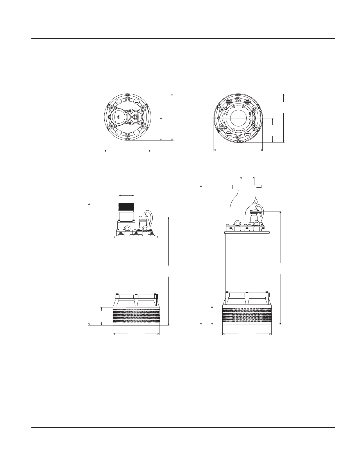
ST4125G/ST6125G SUBMERSIBLE PUMP — DIMENSIONS
34.21 in.
(869 mm)
12.72 in.
(323 mm)
6.97 in.
(177 mm)
15.47 in.
(393 mm)
3.94 in.
(100 mm)
35.67 in.
ST4125G ST6125G
28.9 in.
(734 mm)
(906 mm)
16.89 in.
(429 mm)
5.90 in.
(150 mm)
(323 mm)
6.97 in.
(177 mm)
30.67 in.
(779 mm)
12.72 in.
4.57 in.
(116 mm)
11.89 in.
(302 mm)
4.57 in.
(116 mm)
11.89 in.
(302 mm)
Figure 1. ST4125G/ST6125G Pump Dimensions
ST4125G/ST6125G SUBMERSIBLE PUMP• OPERATION MANUAL — REV. #0 (11/18/10) — PAGE 9
Page 10

ST4125G/ST6125G — GENERAL INFORMATION
The Multiquip Model ST4125G and ST6125G submersible
pumps are designed to pump water. These pumps work
best when faced with high head applications where you
need an appreciable fl ow.
Each pump has dual voltage capability, easily switched
between 230 and 460 volts.
These pumps have a heavy-duty cast iron body that is
very durable and able to withstand rough handling. The
ST4125G comes with a 4-inch NPT threads for standard
hose connections while the ST6125G is equipped with
6-inch fl ange fi tting.
The mechanical seal of these pumps operates within an
oil-fi lled chamber that provides positive lubrication. This
helps prevent damage in the event the pump is run dry for
short periods of time.
PAGE 10 — ST4125G/ST6125G SUBMERSIBLE PUMP • OPERATION MANUAL — REV. #0 (11/18/10)
Page 11

ST4125G/ST6125G — COMPONENTS
4
3 3
2 2
4
55
66
1 1
Figure 2. Submersible Pump Components
Figure 2 shows the location of the basic components, for
the ST4125G and ST6125G submersible pumps. Listed
below is a brief explanation of each component.
1. Strainer Base – This strainer base is made of stainless
steel which is resistant to hardware corrosion. For
dewatering purposes, always place the strainer base
on a platform.
2. Volute/Impeller – Impellers are constructed of cast
ductile iron to minimize wear and prolong service life.
3. Electric Motor – The ST4125G pump utilizes a 60
Hz, three-phase, 230/460 VAC, 10 HP electric motor
and the ST6125G pump utilizes a 60 Hz, three-phase,
230/460 VAC, 15 HP electric motor. Consult with a
licensed electrician before connecting motor to a power
source. Observe all city and local safety codes.
4. Discharge Port – Connect a 4-inch hose (ST4125G)
or 6-inch hose (ST6125G) to this port. Remember to
adequately support the discharge hose to avoid stress
on the pump.
88
77
5. AC Power Cable – These pumps are supplied with a
50 ft. (15.2 meters) AC power cable. Always check the
cable for signs of wear. NEVER use a defective power
cable. Replace the cable immediately if the cable is
worn or defective.
6. Eye Bolts – Always lift the submersible pump by the
eye bolts using a chain and lifting device capable of
lifting about 400 lbs. NEVER lift the pump by its power
cord! Lifting the pump by the power cord will cause
undue stress on the cord and ultimately the cord will
become dislodged from the pump.
7. Mechanical Seal Oil – This oil-fi lled seal provides
lubrication when running the pump dry. NEVER run the
pump dry! Running the pump dry will cause severe
damage to the pump.
8. Mechanical Seal Oil Plug – Remove this plug to
check and add ISO VG32 lubrication oil, Mobile DTE
24, turbine oil 90 or equivalent to the oil chamber. This
oil protects the mechanical seal. Oil chamber should
be full enough to cover seal spring.
ST4125G/ST6125G SUBMERSIBLE PUMP• OPERATION MANUAL — REV. #0 (11/18/10) — PAGE 11
Page 12

FLOAT SWITCHES
Mechanical Float Switch
Mechanically activated fl oat switches offer a reliable low
current control for dewatering applications.
How It Works
The mechanical fl oat switch control will turn ON (close)
when the fl oat tips 45° above -horizontal, indicating a high
level, and turns OFF (opens) when the fl oat switch drops
45° below horizontal. Reference Figure 4 and Figure 5.
Maximum pumping range is 120 degrees. See Figure 3
below.
PUMP
ON
60
120
Design Features
Float switch housings are constructed of high-impact,
corrosion resistant polypropylene with mechanically
activated, snap action contacts.
Suitable for most liquid environments.
Hermetically sealed.
Thick-walled non-corrosive PVC plastic enclosure.
Pressure tested to 30 ft. (9 meters).
Standard SJO, 16-gauge, 2 conductor cord (20 ft./6.09 m).
CONTACTS
CLOSED
ON/OFF
RAMP
STEEL
BALL
SUBMERSIBLE
PUMP
PUMP
OFF
60
Figure 3. Pumping Range (Float Switch)
Pumping Range
The pumping range of the pump is determined by the fl oat
switch tether cord. Use Table 2 as guide line to determine
your required pumping range. Pumping ranges are based
on non-turbulent conditions. Range may vary due to water
temperature and cord shape. Please note as the tether
length increases, so does the variance of the pumping
range.
Table 2. Pumping Range
Tether Length
Pumping Range
2 in.
5.08 cm.
6 in.
15.24 cm.
4 in.
10.16 cm.
10 in.
25.4 cm.
6 in.
15.24 cm.
14 in.
35.56 cm.
8 in.
20.32 cm.
18 in.
45.72 cm.
Figure 4. Float Switch (Closed)
CONTACTS
OPEN
STEEL
BALL
ON/OFF
RAMP
Figure 5. Float Switch (Open)
10 in.
25.4 cm.
22 in.
55.88 cm.
12 in.
30.48 cm.
27 in.
68.58 cm.
14 in.
35.56 cm.
31 in.
78.74 cm.
16 in.
40.46 cm.
35 in.
88.9 cm.
PAGE 12 — ST4125G/ST6125G SUBMERSIBLE PUMP • OPERATION MANUAL — REV. #0 (11/18/10)
Page 13

FLOAT SWITCHES
Float Switches
For unattended operation of the submersible pump two
single fl oat switches (Model SW-1WOPA) will be required.
These fl oat switches can be connected directly to a control
box (bare wires) and will allow the pump to turn on and off
depending on the length of the tether.
EXTERNAL 3-PHASE
(230 OR 460 VOLT)
POWER SOURCE
CIRCUIT
BREAKER
L1
L2
L3
BLACK
TO CONTROL BOX
RED
WHITE
GREEN
INPUT POWER
Mounting The Float Switches
1. Determine the required cord tether length as shown
in Figure 3 and Table 2.
2. Place the cord into the clamp as shown in Figure 6.
3. Secure the clamp to the discharge hose as shown in
Figure 6. DO NOT install cord under hose clamp.
4. Using a screwdriver, tighten the hose clamp. DO NOT
over- tighten. Make sure the fl oat cord is not allowed
to touch the excess hose clamp band during operation.
CAUTION!
HIGH
VOLTAGE!
CONTROL
BOX
RESET
CB12/14
PUMP POWER
CABLE
GND.
3.5 in. (9 cm.)
MINIMUM
TETHER
LENGTH
DISCHARGE
HOSE
SUBMERSIBLE
PUMP
FLOAT SWITCH
CABLES (2)
PUMP
ON
MODEL SW-1WOPA
FLOAT SWITCH (2)
PUMP
OFF
PUMPING
RANGE
Figure 6. Float Switch Application
ST4125G/ST6125G SUBMERSIBLE PUMP• OPERATION MANUAL — REV. #0 (11/18/10) — PAGE 13
Page 14

CB12/CB14 Control Boxes
CAUTION!
HIGH
VOLTAGE!
CB12/14
FLOAT SWITCHES
For remote pumping applications, both submersible pumps,
require a control box (Figure 7).
The CB12 control box requires 230VAC, 3-phase input
voltage for normal operation, while the CB14 control box
requires 460VAC, 3-phase input voltage. Reference Table 3
for the desired heater. The heater size is determined by the
the full load amps the pump will draw.
These water-resistant control boxes provide electronic
overload protection a watertight enclosure and glands to
prevent water from leaking into the box, and a fl oat switch
interface.
Each control box will require the use of two SW-1WOPA
fl oat switches, no plug, bare wires for direct connection
to the control box. Reference Figure 21 for a schematic
reprensentation of the control box.
NOTICE
Contact Multiquip sales department to order control
boxes as listed in Table 3.
CAUTION!
HIGH
VOLTAGE!
MAN
RESET
Figure 7. Electrical Control Box
(Model CB12/14)
OFF
AUTO
Control Box
Model No.
Used With
Pump Model
CB12 ST-4125G
CB12 ST-6125G
CB14 ST-4125G
CB14 ST-6125G
Table 3. Control Box Specifi cations
VoltageType
230 VAC
Three-Phase
230 VAC
Three-Phase
460 VAC
Three-Phase
460 VAC
Three-Phase
Heater
Size
K67 27 YES YES YES
K73 39 YES YES YES
K56 14 YES YES YES
K62 19.7 YES YES YES
Full Load
Amps
UL/CSA
Listed
Thermal
Overload
Protection
Float
Switch
Capability
PAGE 14 — ST4125G/ST6125G SUBMERSIBLE PUMP • OPERATION MANUAL — REV. #0 (11/18/10)
Page 15

CONTROL BOX INSTALLATION
Control Box Installation
The following procedure outlines the steps for connecting
the pump to a control box.
DANGER
The ST4125G and ST6125G submersible
pumps are designed to work with a control
box.This control box contains the necessary
electronics (fl oat switch connections) to
operate the pump. Remember this control
box contains hazardous voltages. Disconnect all
sources of power before installing or servicing. There
exists the possibility of electrocution, electric shock
or burn, which can cause severe bodily harm or even
death!
DANGER
When installing the control box, the
possibility exists of electrical shock,
electrocution and possibly death! NEVER
have untrained personnel perform the
installation. ALWAYS have qualified
service personnel (licensed electrician) perform the
installation.
CONTROL BOX MOUNTING
Mount the control box in an upright vertical position. Make
sure the control box is securely fastened to a fl at surface,
that is free of dust, dirt, moisture or any elements that
may contaminate or erode the electronic components of
the control box.
3-Phase Power Installation (Input)
The ST-4125G/ST6125G submersible pumps require 230
or 460V 3-phase power for normal operation. Each pump
is shipped from the factory in the 230 VAC confi guration. To
change the voltage setting from 230 VAC to 460 VAC refer
to the 230/460 VAC voltage selection section (Figure 8).
If you cannot determine what your pump's power
requirements are, look at the vendor supplied identifi cation
name tag attached to the pump or please contact Multiquip's
Service/Technical Assistance department.
CAUTION
Applying incorrect power (voltage phasing) to the
submersible pump can cause severe damage to the
pump. Please make sure that the correct voltage and
phase are applied to the pump at all times.
WARNING
Explosion or Fire Hazard exists if this pump
is used with fl ammable liquids. DO NOT use
this pump with fl ammable liquids. DO NOT
install this pump in hazardous locations as
defi ned by the National Electrical Code,
ANSI/NFPA 70.
Power Cord Requirements
When routing the 230/460 VAC, 60 Hz., 3-phase power
via a power cord to the control box, ALWAYS use the
correct wire size. Please refer to Table 4 to determine the
correct wire size. Incorrect wire size can adversely affect
the performance of the pump and may ultimately burn out
the pump motor.
Table 4. Power Cord Length
and Wire Size
AMPS
15 12 AWG 10 AWG 8 AWG 6 AWG
20 10 AWG 8 AWG 6 AWG 4 AWG
25 10 AWG 6 AWG 6 AWG 4 AWG
30 10 AWG 6 AWG 4 AWG 2 AWG
40 8 AWG 6 AWG 4 AWG 2 AWG
10 FT.
(3.0 m)
20 FT.
(6.0 m)
30 FT.
(9.1 m)
50 FT.
(15.2 m)
ST4125G/ST6125G SUBMERSIBLE PUMP• OPERATION MANUAL — REV. #0 (11/18/10) — PAGE 15
Page 16

Connecting SW-1WOPA Float Switches to Control
Box
1. Remove the fl oat switch input connector housing, then
route the fl oat switch wires through the cable gland on
the control box. Attach the wires of the fl oat switch to
the terminal block as indicated by Table 5 and Figure 9.
Table 5. Dual Float switch Connections
CONTROL BOX INSTALLATION
Float
Switch
Start
Stop
2. Tighten the connector housing to ensure a tight fi t
between the cord and the connector body. This will
prevent the cable from pulling out of the terminal block
and also prevent moisture from entering the control box.
3. Determine the tether length of the fl oat switch wires
then secure fl oat switch wires to pump discharge hose.
See Figure 3 and Table 2 to determine the pumping
range.
Terminal
Block No.
TB1-A1
TB1-A2
TB1-A3
TB1-A4
Wire
Color
Black
White
Black
White
PAGE 16 — ST4125G/ST6125G SUBMERSIBLE PUMP • OPERATION MANUAL — REV. #0 (11/18/10)
Page 17

230/460 VAC VOLTAGE SELECTION
230/460 VAC Voltage Selection
The ST4125G/ST6125G submersible pumps are factory
set at 230 VAC. To change the voltage from 230 VAC to 460
VAC, reference Figure 8:
230 VAC
REMOVE
SLEEVING
T1
BLACK
T9
T3
T2
T8
T9
T8
T7
T3
T2
T1
WHITE
BLACK
T7
T6
T5
T5
T4
T6
T4
MOTOR WINDING CONFIGURATION
RED
GROUND
GREEN
BLACK
460 VAC
T1
BLACK
T3
T2
T9
T8
T7
T6
T5
T4
T3
T2
460 VAC
(HIGH VOLTAGE)
U
GROUND
GREEN
BLACK
T1
T5
T4
RED
WHITE
BLACK
T9
T6
T8
T7
230 VAC
(LOW VOLTAGE)
W
X
Z
98U
Y
MOTOR
WINDING
STAR WITH
V
NEUTRAL
7
9
Z
W
X
7
MOTOR
WINDING
STAR WITH
NEUTRAL
8
Y
V
Figure 8. 230/460 VAC Electric Motor Windings
ST4125G/ST6125G SUBMERSIBLE PUMP• OPERATION MANUAL — REV. #0 (11/18/10) — PAGE 17
Page 18

CB12/CB14 CONTROL BOX POWER CONNECTIONS
3-Phase Power Installation (Input to Control Box)
1. The 3-phase input power cord should have four wires.
Each wire is color coded. The colors are RED, WHITE,
BLACK and GREEN.
2. Remove the 3-phase AC input connector housing from
the control box, then route the three phase input power
cable through the cable gland on the control box. Attach
the wires to the AC terminal block inside the control
box as indicated by Table 7 and Figure 9.
Table 6. 3Ø-230/460 VAC
Input Power Connections
Wire Color
RED L1
WHITE L2
BLACK L3
GREEN GROUND
Input Power
Terminal Block
3-Phase Power Installation (Output To Pump)
1. The 3-phase output power cord should have four wires.
Each wire is color coded. The colors are RED, WHITE,
BLACK and GREEN.
2. Remove the 3-phase AC output power connector
housing on the control box, then route the output power
cable through the cable gland on the control box.
Attach the wires to the AC terminals on the overload
relay module as indicated by Table 7 and Figure 9.
Table 7. 3Ø-230/460 VAC
Output Power Connections
Wire Color
RED T1
WHITE T2
BLACK T3
GREEN GROUND
Output Power
Overload Relay
3. Tighten the connector housing to ensure a tight fi t
between the power cord and the connector body. This
will prevent the cable from pulling out of the terminal
block and also prevent moisture from entering the
control box.
4. Connect the other end of the 3-phase input power cord
to the voltage source. Remember to provide a means
of disconnecting the power from the control box (circuit
breaker or quick disconnect switch). Also make sure
to provide a good earth ground to the control box.
NOTICE
It is recommended that the power being supplied to the
control box ALWAYS be connected to a circuit breaker
or a quick disconnect switch. This safety feature allows
for quick removal of power from the control box in the
event of an emergency.
PAGE 18 — ST4125G/ST6125G SUBMERSIBLE PUMP • OPERATION MANUAL — REV. #0 (11/18/10)
Page 19

MOUNT CONTROL
BOX IN AN UP-LEFT
VERTICAL POSITION
CONTROLLER
AC POWER
TERMINAL BLOCK
FLOAT SWITCH
TERMINAL BLOCK
EXTERNAL 3-PHASE
(230 OR 460 VOLT)
POWER SOURCE
CIRCUIT
BREAKER
L1
L2
L3
WHITE
BLACK
AS SHOWN.
RED
GREEN
CB12/CB14 CONTROL BOX WIRING LAYOUT
702X
LISTED
TRANSFORMER
(708) 547-0900
CONTROL
04024
MICRON
X2
NO.
CAT.
H1
B075BTZ13JK
Impervi
U.S.
TEMP.
PAT.
75VA
TRAN
NO.
H3
CL.
3516040
(
R
105
50/60HZ
F
)
N
XF
M
-
8/10
FUSE
C
H2
DUEL-ELE
F
U
T
E
S
X2
1 2 3 4
H1
220
X1
230
110
240
H4
115
H2
120
H3
1
440
2
460
XF
3
H4
480
4
X1
TRANSFORMER
OFF/ON
LAMP
6
1
3
0
1
MANUAL/AUTO
/0
L3L
2
3
M
A
I
N
T
R
I
P
T
T
3
2
3
2
5
0
-
0
2
SWITCH
OVERLOAD
RELAY
HEATER
BLKRED WHT
GRN
SEE TABLE 2
3 PHASE
AC OUTPUT
POWER CABLE
L1
RED
WHT
L11
3
L2
1- 2- 3- 4-
1- 2- 3- 4-
4
T12T12T36T2
AEG
13
2
4
L2 L3
BLK
L35
-3
-4
FLOAT
SWITCH
INPUTS
L1L2L
R
E
S
E
T
T
1
BLACK
GRN
GROUND
3 PHASE
AC INPUT
POWER CABLE
WARNING
CONTROL BOX INSTALLATION IS TO BE
PERF ORMED BY A LICENSED ELECTRICI AN
OR QUALIFIED PERSONNEL.
THE POSSIBILITY OF ELECTRICAL SHOCK
OR ELECTROCUTION EXISTS, WHICH COULD
CAUSE SE VERE BODILY HARM E VEN DE ATH!.
Control Box/Pump System Diagram
3. STOP FLOAT
SWITCH. CONNECT
TO TERMINALS 3 AND 4
Figure 9. Three Phase
1.SECURE FLOAT SWITCH
WIRES TO PUMP
DISCHARGE HOSE
2. START FLOAT
SWITCH. CONNECT
TO TERMINALS 1 AND 2
PUMPING
RANGE
ST4125G/ST6125G SUBMERSIBLE PUMP• OPERATION MANUAL — REV. #0 (11/18/10) — PAGE 19
Page 20

OPERATION
Pump Placement
1. Attach a suitable lifting chain to the eye bolts (Figure 10)
on the pump. Use a crane, or similar lifting device and
lower the pump into place. For applications where there
is an excessive amount of mud, grit or silt, the use of
a support platform is desirable.
LOWER
4 or 6-INCH
DISCHARGE
HOSE
LIFTING
CHAIN
CONNECT
TO CONTROL
BOX
POWER
CORD
2. Make sure the pump is always placed in an upright
position, not tilted (Figure 11). Never position the pump
directly on a soft, loose bottom. To attain maximum
pumping capacity and prevent excessive wear, position
the pump so it will not burrow itself into sand or clay.
LOWER
SUPPORT
PLATFORM
Figure 10. Placing the Submersible Pump
(Correct Upright Position)
Figure 11. Tilted Position (Incorrect)
Control Box Operation (Manual Mode)
PAGE 20 — ST4125G/ST6125G SUBMERSIBLE PUMP • OPERATION MANUAL — REV. #0 (11/18/10)
Page 21

OPERATION
1. From the voltage source, set the circuit breaker or quick
disconnect switch to the ON position.
2. For manual operation of the pump, place the 3-position
operation switch (Figure 12) on the control box in the
MANUAL position.
Figure 12. Manual-Off-Auto SW.
(Manual Position)
3. Verify that the ON indicator (Figure 13) on the control
box is LIT. This means that power is being supplied to
the control box.
Figure 13. Control Box Power ON Indicator
4. In the manual mode the pump will run continuously. Pay
close attention when running the pump in this mode.
DAMAGE to the pump may occur if pump is not fully
immersed in water.
Control Box Operation (Auto Mode)
1. To operate the pump automatically (fl oat switches),
place the 3-position operation switch in the AUTO
position (Figure 14).
1. When the electronic overload module detects an
overload condition, the pump will shut down. Check the
pump and correct the cause of ther overload.
2. Let the pump cool down, then press the RESET button
(see Figure 15) on the front of the control box to restore
power.
Figure 15. RESET Button
Shut-Down
1. Place the 3-position operation switch on the control
box to the OFF position (Figure 16).
Figure 16. Manual-Off-Auto SW.
(OFF Position)
2. Verify that the control box power ON light is OFF.
3. Turn the circuit breaker or quick disconnect switch to
the OFF position.
4. Using a suitable lifting device, lift the pump up from
its current position and place on a secure fl at surface.
Figure 14. Manual-Off-Auto SW.
(Auto Position)
2. In the AUTO mode the pump will run as long as there
is a suffi cient amount of water. This amount of water
is determined by the setting of the fl oat switches. The
stop fl oat switch contacts will open when the water
level is low and power will be removed from the pump's
electric motor.
Once the water level has risen back to the appropriate
level the start fl oat switch contacts will close and power
will be restored to the pump's motor.
Reset Button
ST4125G/ST6125G SUBMERSIBLE PUMP• OPERATION MANUAL — REV. #0 (11/18/10) — PAGE 21
5. Remove the discharge hose from the discharge port
on the pump.
6. Remove all power cables and fl oat switches from
the control box. Place cables and fl oat switches in a
suitable container where they will not get damaged.
7. If the pump was used to pump mud, grit or silt, fl ush
vigorously with clean water.
8. Wipe off any mud or debris that might have attached
itself to the pump.
9. Store pump in a clean dry place away from dirt and
debris.
Page 22

MAINTENANCE
Lubrication
To check the lubrication oil level of the mechanical seal
perform the following:
Checking Lubrication Oil Level
1. Lay the pump (Figure 17) on its side with the oil plug
facing upwards.
2. Remove oil fi ll plug.
3. Visually inspect oil plug hole to verify that oil chamber
is full enough to cover seal spring.
4. When reinstalling oil fi ll plug, apply tefl on tape to
prevent leaking.
WARNING
When removing oil fi ll plug, please note
that pressure may have built up in the oil
chamber. DO NOT fully remove plug until
pressure has been relieved. Turn oil fi ll plug
slowly to relieve pressure.
Inspecting Lubrication Oil (Mechanical Seal)
1. Block the oil fi ll opening with a fi nger and roll pump to
one side to drain (Figure 18) oil into a small transparent
container.
2. If oil is cloudy (milky) or has water in it, indicates
that mechanical seal is defective or worn. Replace
mechanical seal.
Figure 18. Lubrication Oil Inspection
Changing Lubrication Oil
1. If lubrication oil level is low, block the oil fi ll opening
with a fi nger and roll pump to one side to drain oil into
a small container.
2. Use a funnel (Figure 17) and fi ll oil chamber with ISO
VG32 lubrication oil or equivalent. Oil chamber
capacity is 74.4 oz. (2.2 liters). Fill to 75-80% capacity
to allow for expansion. Replace lubrication oil once a
year or 3,000 hours.
REMOVE FILL PLUG, AND
VISUALLY INSPECT THAT
OIL CHAMBER IS FULL ENOUGH
TO COVER SEAL SPRING.
FILL TO 75-80% CAPACITY
(APPROXIMATELY 74.4 OZ. (2.2 LITERS)
FILL WITH ISO VG32 LUBRICATION
LAY PUMP FLAT
ON ITS SIDE
Figure 17. Adding Lubrication Oil
OIL OR EQUIVALENT.
CHECK HYDRAULIC OIL ONCE
A YEAR OR EVERY 3000 HOURS.
NOTICE
When replacing the oil in the oil chamber, shaft seal
MUST be changed at the same time.
PAGE 22 — ST4125G/ST6125G SUBMERSIBLE PUMP • OPERATION MANUAL — REV. #0 (11/18/10)
Page 23

MAINTENANCE
Impeller Removal
Refer to the the following procedure and Figure 19 for the
removal of the impeller.
1. Remove oil plug (item 193) and o-ring (item 194). Drain
oil from oil chamber as referenced in Figure 18.
2. Remove suction strainer/ring stand (item 84A).
3. Remove the six suction cover bolts and washers (items
188A/188B) that secure the suction cover (item 189)
to the pump housing (item 50). Remove suction cover
(item 189).
4. Remove impeller cap nut (item 188) and washer (item
66) from motor shaft.
5. Remove impeller (item 49), gap washer (item 49A) and
impeller key (item 9A) from motor shaft.
6. Reassemble in reverse order.
NOTICE
Clearance between impeller and wear plate should
be between .011~.019 in. (0.3~0.5 mm). If impeller is
defective or badly worn, replace immediately.
Long Term Storage
1. Area must be free from excessive humidity, corrosive
gases, vapors or vibrations which might damage the
pump.
2. Store pump in a vertical position on a pallet or stand.
3. Coil up the cable, and seal the open end (control box
wires) with waterproof tape or a cable cap. This will
prevent moisture from penetrating into the motor which
could cause severe damage to the windings.
4. Give all unpainted surfaces a light coat of oil or grease
to prevent corrosion.
5. If new pumps are stored for more than two months, turn
the impeller by hand every two months to prevent the
mechanical seal faces from seizing up. Failure to do this
may result in seal damage when the pump is started.
Water Tank Storage
1. If an installed pump (immersed in water) has not
been in operation for a long period of time, check the
insulation resistance and run the pump for 30 minutes
every month.
If the pump cannot be run due to lack of water in the
tank inspect the pump and turn the impeller by hand
each month and prior to putting the pump back into
service. If insulation drops below 10 megohms, contact
an authorized Multiquip service center.
Figure 19. Impeller Removal
ST4125G/ST6125G SUBMERSIBLE PUMP• OPERATION MANUAL — REV. #0 (11/18/10) — PAGE 23
Page 24

MAINTENANCE
Electrical Insulation Testing
Why perform electrical insulation testing?
Electrical insulation starts to age as soon as it is made.
Harsh environments, especially those with extreme
temperature changes and/or chemical contamination,
cause further deterioration of the insulation (power cord).
As a result, personnel safety (electrocution/shock) and
power reliability can suffer resulting in higher operating
cost and maintenance.
What is Insulation Resistance Testing
Insulation resistance testing applies a regulated stabilized
high voltage (Figure 20), typically 500 VDC or greater
across a dielectric (power cord). Measuring the amount of
leakage current fl owing through the dielectric will yield a
resistive measurement in megohms.
Insulating Material Testing
To verify the integrity of the pump's insulating material
(power cable) it will be necessary to perform an electrical
insulation test. Any electrical insulation must have the
opposite characteristic as the conductor: it should resist
the fl ow of current, keeping it within the conductor.
NOTICE
Insulation resistance is moisture and temperature
sensitive. When temperature increases, insulation
resistance decreases, and vice versa.
When performing this test measurement, perform the
test using the same test parameters as used in the
initial testing. Contact an authorized Multiquip service
center if the measured cable insulation is 10 megohms
or less.
20M
W
MW
V
OFF
W
KW
SET
UP
W
500 VDC INSULATION
MEGGER™
TEST METER
POWER CABLE
INSULATION
GROUND WIRE
(GREEN)
SUBMERSIBLE
PUMP
To measure the IR (current x resistance), the use of an IR
tester must be employed. This IR tester is a portable device
that is a resistance meter (ohmmeter) with a built in DC
generator that develops a high DC voltage.
The high DC voltage from the IR tester is usually 500 VDC
or more. This voltage, when applied causes a small current
to fl ow through and over the insulation's surfaces. The tester
provides a direct reading of IR in megohms.
A high resistance reading would indicate a "good"
insulation, meaning very little current is escaping through
the insulation. While a relatively low resistance reading
would indicate a poor insulation, meaning a signifi cant
amount of current may be leaking through and along the
insulation.
Figure 20. Insulation Tester Application
DANGER
Read and follow the manufacturer's user's
manual prior to operating insulation tester
(megaohm meter). This meter generates
a test voltage of 500 volts or greater. Only
qualifi ed and trained personnel should
use this equipment. The possibility exists of severe
electrical shock, electrocution even death, when
using insulation tester.
PAGE 24 — ST4125G/ST6125G SUBMERSIBLE PUMP • OPERATION MANUAL — REV. #0 (11/18/10)
Page 25

TROUBLESHOOTING
Table 8. Pump Troubleshooting
SYMPTOM POSSIBLE PROBLEM SOLUTION
Check that the proper voltage, 230 or 460 VAC, 60
Hz, 3-phase is being supplied to the pump. Also
Incorrect voltage/amps?
check that there is an adequate amount of current
(amps) to run the pump. Check power source circuit
breaker.
Pump Fails To Start
Check electrical connections?
Blown power fuse or tripped
circuit breaker?
Impeller locked?
Wet motor windings?
Defective motor and pump
bearings?
Twisted or restricted discharge hose?
Clogged pump strainer? Clean strainer.
If using fl oat switches check wiring, inspect power
cord.
Replace fuse check circuit breaker, check cause of
blown fuse or tripped breaker.
Disconnect power cord and check for clogging. Unclog pump. Check overload protection device.
Use multimeter to check motor insulation. Insulation
resistance must be approximately 15 megaohms. If
resistance is low, disassemble pump motor and bake
windings to dry them.
Check for excessive bearing wear, if worn replace
bearings. Replace motor if defective.
Lay hose fl at un-kinked. Remove clog from hose line.
Pump Fails to Deliver Full
Output
Low voltage?
Impeller worn? Replace impeller.
Water in Mechanical
Seal Oil
ST4125G/ST6125G SUBMERSIBLE PUMP• OPERATION MANUAL — REV. #0 (11/18/10) — PAGE 25
Defective mechanical seal? Replace mechanical seal.
Loose Oil Fill Plug? Tighten securely. Apply tefl on tape.
Use a voltmeter to check voltage while pump is
energized. Voltage must be within ±10%. Check
power source (no load and load). If an extension cord
is used, make sure it has adequate current-carrying
capacity for the required length.See Table 4.
Page 26

CB12/CB14 CONTROL BOX WIRING DIAGRAM
EXTERNAL 3-PHASE
(230 OR 460 VOLT)
POWER SOURCE
CIRCUIT
BREAKER
L1
L2
L3
WHITE
BLACK
GROUND
RED
GREEN
CB-12/CB-14
POWER
INPUT
L1
L1
L2
L2
L3
L3
H1
F1
XF
FUSE
1/2 AMP
THREE PHASE WIRING
CONNECTIONS
M
CONTROL
50VA CPT
RED
3
AWG 10
X1
RED AWG 8
RED AWG 8
RED AWG 8
H3
BLK
H2
H4
TRANSFORMER
WHT
X2
GRN
MAN
2
1
OFF
AUTO
4
AWG 10
NO
RED
O/L
RED
WHT
BLK
SEE TABLE 2
FOR CORRECT
HEATER SELECTION
OVERLOAD
RELAY
T1
T2
T3
PUMP
MOTOR
GRN
O/L
NC
RED
AWG 10
CONTACTOR
4
A2
TERMINAL
BLOCK
X2
ON
INDICATOR
LAMP
G
5HP
M
A1
WHT
AWG 10
WHT AWG 10
SELECTABLE 230 OR 460 VAC
VOLTAGE INPUTS
FUSE
X1
XF
120
115
X1
110
H4 H2 H3 H1
X2
Figure 21. CB12/CB14 Control Box Wiring Diagram
JUMPER
TRANSFORMER
TAB
43 2
STOP
FLOAT
SWITCH
START
FLOAT
SWITCH
L1 L2
230V INPUT
H2
H1
H3
H4
CB-12
1
L1 L2
460V INPUT
H1
H3
H2
H4
CB-14
PAGE 26 — ST4125G/ST6125G SUBMERSIBLE PUMP • OPERATION MANUAL — REV. #0 (11/18/10)
Page 27

NOTES
ST4125G/ST6125G SUBMERSIBLE PUMP• OPERATION MANUAL — REV. #0 (11/18/10) — PAGE 27
Page 28

OPERATION AND PARTS MANUAL
©
HERE’S HOW TO GET HELP
PLEASE HAVE THE MODEL AND SERIAL
NUMBER ON-HAND WHEN CALLING
UNITED STATES
Multiquip Corporate Offi ce MQ Parts Department
18910 Wilmington Ave.
Carson, CA 90746
Contact: mq@multiquip.com
Service Department Warranty Department
Tel. (800) 421-1244
Fax (800) 537-3927
800-427-1244
310-537-3700
Fax: 800-672-7877
Fax: 310-637-3284
800-421-1244
310-537-3700
Technical Assistance
800-478-1244 Fax: 310-943-2238
Fax: 310-537-4259 800-421-1244
310-537-3700
Fax: 310-537-1173
MEXICO UNITED KINGDOM
MQ Cipsa Multiquip (UK) Limited Head Offi ce
Carr. Fed. Mexico-Puebla KM 126.5
Momoxpan, Cholula, Puebla 72760 Mexico
Contact: pmastretta@cipsa.com.mx
Tel: (52) 222-225-9900
Fax: (52) 222-285-0420
Unit 2, Northpoint Industrial Estate,
Globe Lane,
Dukinfi eld, Cheshire SK16 4UJ
Contact: sales@multiquip.co.uk
Tel: 0161 339 2223
Fax: 0161 339 3226
CANADA
Multiquip
4110 Industriel Boul.
Laval, Quebec, Canada H7L 6V3
Contact: jmartin@multiquip.com
COPYRIGHT 2010, MULTIQUIP INC.
Multiquip Inc and the MQ logo are registered trademarks of Multiquip Inc. and may not be used, reproduced, or altered without written permission. All other trademarks are the property
of their respective owners and used with permission.
This manual MUST accompany the equipment at all times. This manual is considered a permanent part of the equipment and should remain with the unit if resold.
The information and specifi cations included in this publication were in effect at the time of approval for printing. Illustrations, descriptions, references and technical data contained in
this manual are for guidance only and may not be considered as binding. Multiquip Inc. reserves the right to discontinue or change specifi cations, design or the information published
in this publication at any time without notice and without incurring any obligations.
Tel: (450) 625-2244
Tel: (877) 963-4411
Fax: (450) 625-8664
Your Local Dealer is:
 Loading...